

Panasonic SBPF-460-GC Service manual
Type
Speaker
1.
2.
Input
Output
Cross
Frequency
Specification
ORDER NO. MD0707002CE
Speaker System
SB-PF460GC
Colour
(S)... Silver Type
2 way, 2 speaker system (Bass reflex)
unit(s) Impedance 3 Ω
Tweeter 6 cm cone type
Woofer 16 cm cone type
power (IEC) 115 W (Max)
sound pressure 95.8dB/W(1.0m)
over frequency 5.8 kHz
range 21 Hz to 24 kHz (-16 dB)
55 Hz to 18 kHz (-10 dB)
Dimensions (W x H x D) 219mm x 330mm x 196 mm
Mass 2.6 kg
Notes :
1. Specifications are subject to change without notice.
Mass and dimensions are approximate.
2. Total harmonic distortion is measured by the digital spectrum
analyzer.
© 2007 Matsushita Electric Industrial Co. Ltd.. All
rights reserved. Unauthorized copying and
distribution is a violation of law.
SB-PF460GC
1 System Combination
1.1. System Breakdown
Note :
The tables below show the breakdown for speaker combinations used in main unit systems.
System SC-VK460EE-S
Music center SA-VK460EE-S
Front speaker
System SC-VK460GC-S
Music center SA-VK460GC-S
Front speaker
System SC-VK460GCSS
Music center SA-VK460GCSS
Front speaker
System SC-VK460GCTS
Music center SA-VK460GCTS
Front speaker
System SC-VK460GS-S
Music center SA-VK460GS-S
Front speaker
SB-PF460GC-S
SB-PF460GC-S
SB-PF460GC-S
SB-PF460GC-S
SB-PF460GC-S
2
2 Assembling and Disassembling
“ATTENTION SERVICER”
Some chassis components may have sharp edges. Be careful when disassembling and servicing.
1. This section describes procedures for checking the operation and replacing the main components.
2. For reassembly after operation checks or replacement, reverse the respective procedures.
Special reassembly procedures are described only when required.
3. Select items from the following index when checks or replacement are required.
4. Refer to the Parts No. on the page of “Parts Location and Replacement Parts List” (Section 5), if necessary.
Below is the list of disassembly sections
• Disassembly of Rear cabinet assembly
• Disassembly of Tweeter (SP1)
• Disassembly of Woofer (SP2)
SB-PF460GC
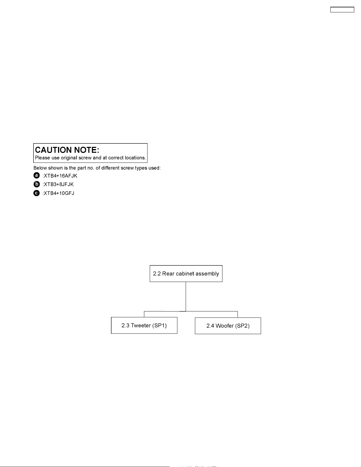
2.1. Disassembly flow chart
The following chart is the procedure for disassembling the casing and inside parts for internal inspection when carrying out the
servicing.
To assemble the unit, reverse the steps shown in the chart as below.
3
SB-PF460GC
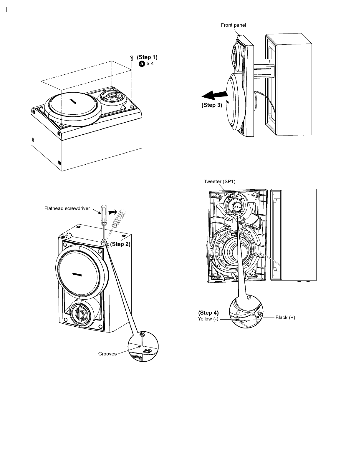
2.2. Disassembly of Rear cabinet
assembly
Step 3: Detach the front panel as arrow shown.
Step 1: Remove 4 screws.
Step 4: Detach the black (+) and yellow (-) wires.
Step 2: Insert flathead screwdriver into the grooves to push the
front panel as arrow shown.
4
 Loading...