

Page 1

Specification
Type 1 way, 1 speaker system
Speaker (s)
Full Range 8 cm (3-5/32”) cone type (6 Ω)
Impedance 6 Ω
Input power (IEC) 15 W (Max)
Output sound pressure 79.05 dB/W (1.0 m)
Frequency range 55 Hz to 25 kHz (-16 dB)
60 Hz to 20 kHz (-10 dB)
Dimensions (W x H x D) 127 x 178 x 228 mm
ORDER NO. MD0703019CE
A6
Speaker System
SB-NS55P
Colour
(K)... Black Type
(5” x 7” x 9”)
Mass 1.4kg(3.1lb.)
Notes :
1. Specifications are subject to change without notice.
Mass and dimensions are approximate.
2. Total harmonic distortion is measured by the digital spectrum
analyzer.
CONTENTS
Page Page
1 System Combination
1.1. System Breakdown
2 Assembling and Disassembling
2.1. Disassembly flow chart
2.2. Disassembly of Stand base
2.3. Disassembly of Net frame assembly
2.4. Disassembly of Woofer unit
3 Connection of the Speaker Cables
2
4 Connection of the Wiring Diagram
2
3
5 Exploded view
3
4
4
5
5.1. Cabinet Parts Location
5.2. Packaging
6 Replacement Parts List
© 2007 Matsushita Electric Industrial Co. Ltd.. All
rights reserved. Unauthorized copying and
distribution is a violation of law.
10
11
7
8
9
9
Page 2

SB-NS55P
1 System Combination
1.1. System Breakdown
Note : The table below show the breakdown for speaker combinations used in main unit systems.
System SC-NS55P-K
Music center SA-NS55P-K
Speaker system SB-NS55P-K
2
Page 3

2 Assembling and Disassembling
“ATTENTION SERVICER”
Some chassis components may have sharp edges. Be careful when disassembling and servicing.
1. This section describes procedures for checking the operation of the major printed circuit boards and replacing the main
components.
2. For reassembly after operation checks or replacement, reverse the respective procedures.
Special reassembly procedures are described only when required.
3. Select items from the following index when checks or replacement are required.
4. Refer to the Parts No. on the page of “Parts Location and Replacement Parts List” (Section 6), if necessary.
Below is the list of disassembly sections
· Disasse mbly of Stand base
· Disasse mbly of Net frame assembly
· Disasse mbly of Woofer unit
SB-NS55P
2.1. Disassembly flow chart
The following chart is the procedure for disassembling the casing and inside parts for internal inspection when carrying out the
servicing.
To assemble the unit, reverse the steps shown in the chart as below.
3
Page 4
SB-NS55P
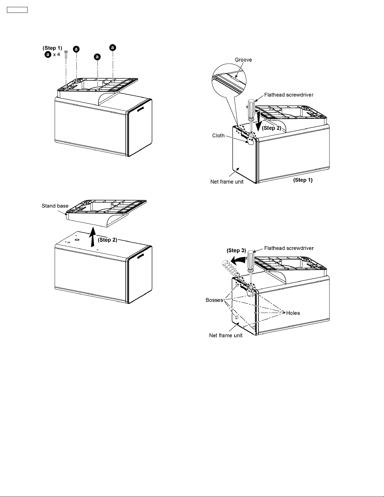
2.2. Disassembly of Stand base
Step 1: Remove 4 screws.
2.3. Disassembly of Net frame
assembly
Step 2: Remove stand base as arrow shown.
Step 1: Upset the speaker cabinet as shown above.
Step 2: Insert the flathead screwdriver above the cloth into the
groove of speaker cabine t.
Step 3: Push the net frame unit with the flathead screwdriver
as arrow shown.
Caution: Do not exert too much force on the bosses and holes
as it may damage the net frame unit.
4
Page 5

Step 4: Remove net frame unit as arrow shown.
SB-NS55P
Step 2: Insert the steel rule in between the woofer unit and
speaker cabinet to push out the woofer unit.
Step 5: Remove net frame assembly as arrow shown.
2.4. Disassembly of Woofer unit
Follow (step 1) to (step 4) in item 2.3.
Step 3: Detach the red (+) and black (-) wires.
Step 1: Remove 4 screws.
5
Page 6

SB-NS55P
Step 4: Remove woofer unit as arrow shown.
6
Page 7

3 Connection of the Speaker Cables
· Be sure to connect speaker cables before connecting the
AC power supply cord.
· The load impedance of any speaker used with this unit must
be 6 Ω.
· Be sure to connect the cable from the right speaker to the
right terminal and the cable from the left speake r to the left
terminal.
1. Twist and pull off the vinyl tip of the speaker cords. If the
speaker cords do not have vinyl tips, connect them directly
to the terminals. Make sure the bare ends of the wires are
not unravelled.
2. Insert the wire to the rear panel of the unit and close the
lever.
Notes :
· To prevent damage to circuitry, never short-circuit positive
(+) and negative (-) speaker wires.
· Be sure to connect only positive (red) wires to positive (+)
terminals and negative (black) wires to negative (-)
terminals.
SB-NS55P
Placement of speakers
7
Page 8

SB-NS55P
4 Connection of the Wiring Diagram
8
Page 9

5 Exploded view
5.1. Cabinet Parts Location
SB-NS55P
9
Page 10

SB-NS55P
5.2. Packaging
10
Page 11

6 Replacement Parts List
Notes :
· Important safety notice :
When replacing any of these components, be sure to use
only manufacturer’s specified parts shown in the parts list.
· [M] markings in the Remarks columns indicates parts
supplied by PAVCSG.
Ref.
No.
1 RFKHBNS55P-K SPEAKER CABINET ASSY [M]
2 RGKV0167-K STAND BASE [M]
3 RGNV0291 SPEC LABEL [M]
4 RGPV0095-K FRONT ORNAMENT [M]
5 RHDV4010-K SCREW [M]
6 RKA0072-KJ LEG CUSHION [M]
7 RMQV0078 SPEAKER GASKET [M]
8 RYBV0047B-K NET FRAME ASS’Y [M]
9 RMQV0092 EVA PACKING [M]
10 XTB4+16AFJK SCREW [M]
P1 RPNV0136 POLYFOAM [M]
P2 RPFV0073 MIRAMAT BAG [M]
Part No. Part Name & Description Remarks
CABINET AND CHASSIS
PACKING MATERIALS
SB-NS55P
SPEAKER
SP1 EAS8P209A WOOFER UNIT [M]
11
FLE0703
 Loading...