

Panasonic SA-HT640WP, SA-HT640WPC, SB-W640, SB-SA640, SB-PC640 Service Manual
...
A
ORDER NO.MD0512492C1
A6
DVD Home Theater Sound System
SA-HT640WP
SA-HT640WPC
Colour
(S).......................Silver Type
Specifications
lGeneral
Power Source:
Power consumption: 85 W
Dimensions (W×H×D): 430×70×439.2 mm
Mass:
lAmplifier section
RMS Output Power: Dolby Digital Mode
lTotal RMS Dolby Digital
mode Power:
At 1kHz and total harmonic of 10%
lFront: 110 W/ Channel (3Ω)
lCenter: 225 W/ Channel (6Ω)
lSurround: 90 W/ Channel (4Ω)
At 100Hz and total harmonic of 10%
lActive subwoofers: 225 W/ Channel (6Ω)
FTC Output Power: Dolby Digital Mode
lTotal FTC Dolby Digital mode Power:
At 120Hz-20kHz and total harmonic of 1%
lFront: 40 W/ Channel (3Ω)
lCenter: 75 W/ Channel (6Ω)
lSurround: 40 W/ Channel (4Ω)
C 120V, 60Hz
(16-15/16”×2-3/4”×17-19/64”)
4.65 kg (10.25Ibs)
850 W
300 W
At 45Hz-120Hz and total harmonic of 1%
lSubwoofer: 65 W/ Channel (6Ω)
lFM tuner section
Preset Memory:: FM 15 stations
AM/MW 15 stations
Frequency Range:
Sensitivity: 2.5µV (IHF)
S/N 26dB
Antenna Terminals: 75Ω (unbalanced)
lAM tuner section (AM/MW)
Frequency Range: 520-1710kHz (10kHz in step)
AM Sensitivity S/N 20dB at
1000kHz:
lPhone Jack:
Terminal: Stereo 3.5 mm (1/8”) jack
lFront/Rear M. Port:
Sensitivity: 100mV (4.7kΩ)
Terminal (Input): Stereo 3.5 mm (1/8”) jack
lDisc section
Discs played [8 cm (3”) or 12 cm (5”)]:
87.9-107.9MHz
(200kHz in step)
87.5-108.0MHz
(100kHz in step)
2.2µV
560µV/m
© 2006 Panasonic AVC Networks Singapore Pte.
Ltd. All rights reserved. Unauthorized copying and
distribution is a violation of law.
V
Y
Y
SA-HT640WP / SA-HT640 WPC
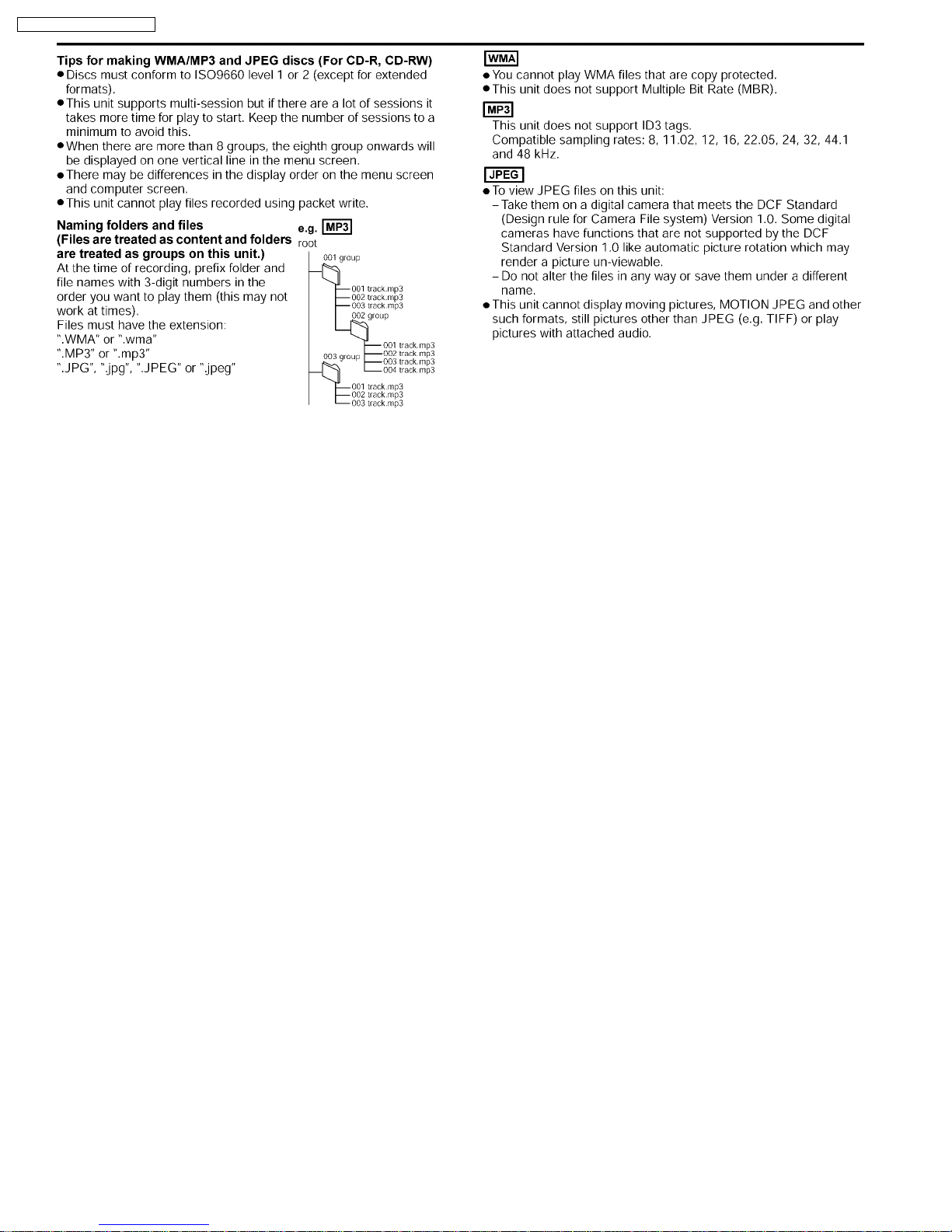
(1) DVD [DVD-Video, DVD-Audio]
(2) DVD-RAM [DVD-VR, JPEG(*4,5)]
(3) DVD-R [DVD-Video]
(4) DVD-RW [DVD-Video]
(5) +R/+RW [Video]
(6) CD, CD-R/RW [CD-DA, Video CD, SVCD(*1), MP3(*2,5),
WMA(*3,5), JPEG(*4,5), HighMAT Level 2 (Audio and
Image)]
*1 Conforming to IEC62107
*2 MPEG-1 Layer 3, MPEG-2 Layer 3
*3 Windows Media Audio Ver.9.0 Class 2A
lNot compatible with Multiple Bit Rate (MBR)
*4 Exif Ver 2.1 JPEG Baseline files
lPicture resolution: between 320 x 240 and 6144 x 4096
pixels (Sub sampling is 4:2:2 or 4:2:0). Extremely long and
thin pictures may not be displayed.
*5 The total combined maximum number of recognizable audio
and picture contents and groups: 4000 audio and picture
contents and 400 groups.
Pick up:
Wavelength:
lCD: 785nm
lDVD: 662nm
Laser power:
lCD: CLASS I
lDVD: CLASS II
Audio output (DISC):
Number of channels:
Audio performance:
Frequency response:
DVD (linear audio):
DVD-Audio: 4 Hz-88 kHz (192 kHz
CD-Audio: 4 Hz-20 kHz
S/N ratio:
CD-Audio: 105 dB
Dynamic range:
DVD (linear audio):
CD-Audio: 95 dB
Total harmonic distortion:
CD-Audio:
lVideo section
ideo system:
Signal system: NTSC
Composite video output:
Output level: 1 Vp-p (75 Ω )
Terminal: Pin jack (1 system)
S-video output:
output level: 1 Vp-p (75 Ω)
C output level: NTSC; 0.286 Vp-p (75 Ω )
Terminal S terminal (1 system)
Component video output (480p/480i):
output level: 1 Vp-p (75 Ω)
5.1 ch (FL, FR, C, SL, SR,
SW)
4 Hz-22 kHz (48 kHz sampling)
4 Hz-44 kHz (96 kHz sampling)
sampling)
95 dB
0.005 %
PBoutput level: 0.7 Vp-p (75 Ω )
PRoutput level: 0.7 Vp-p (75 Ω )
Terminal: Pin jack (Y: green, PB: blue,
P
: red) (1 system)
R
Power consumption in standby mode:
approx 0.4W
Note:
1. Specifications are subject to change without notice.
Mass and dimensions are approximate.
2. Total harmonic distortion is measured by the digital spectrum
analyzer.
Solder:
This model uses lead free solder (PbF).
Mechanism:
This model uses RC1 (Rotary tray) mechanism.
Refer to the original service manual for *1, *2, *3, *4.
2

SA-HT640WP / SA-HT640 WPC
CONTENTS
Page Page
1 Safety Precautions 5
1.1. GENERAL GUIDELINES
1.2. Before Repair and Adjustment
1.3. Protection Circuitry
2 Prevention of Electro Static Discharge (ESD) to
Electrostatically Sensitive (ES) Devices
3 Precaution of Laser Diode
4 About Lead Free Solder (PbF)
5 Handling Precautions for Traverse Unit
5.1. Cautions to Be Taken in Handling the Optical Pickup Unit
5.2. Grounding for electrostatic breakdown prevention
6 Accessories
7 Operation Procedures
7.1. Operating instructions
7.2. Disc information
8 New Features
8.1. RF Wireless Audio Transceiver
8.2. Detail Block Diagram (Receiver module)
8.3. Class-D Amplifier
9 Self-Diagnosis and special mode setting
9.1. Service Mode Summary Table
9.2. Service Mode Table 1
9.3. DVD Self Diagnostic Function-Error Code
9.4. Sales Demonstration Lock Function
9.5. Service Precautions
10 Assembling and Disassembling
10.1. Disassembly Flow Chart
10.2. Main Components and P.C.B. Locations
10.3. Disassembling the Top Cabinet
10.4. Disassembling the Front Panel Assembly
10.5. Disassembling the Tray Assembly
10.6. Disassembling the Rear Panel
10.7. Disassembling the Mechanism Base Assembly
10.8. Disassembling the FL & Head phone P.C.B.
10.9. Disassembling the Main P.C.B.
10.10. Disassembling the AC Inlet, Power & Sub power P.C.B
10.11. Disassembly of Digital Amp IC
10.12. Disassembly of Regulator IC
10.13. Disassembly of Switch Regulator IC (IC5701)
10.14. Disassembly of the Tray Base Guide (L) and Tray Base
Guide (R)
10.15. Disassembly of the Rotary Tray
10.16. Disassembly of the Traverse Unit
10.17. Assembly of Tray Assembly
11 Service Fixture and Tools
12 Service Positions
5
5
6
6
8
8
9
9
9
11
12
12
15
17
17
19
23
27
27
27
32
34
35
36
37
37
38
38
38
39
39
39
39
40
40
40
40
41
41
42
44
46
12.1. Checking & Repair Main P.C.B., Power P.C.B., FL and
Head phone P.C.B.
12.2. Checking & Repair DVD Module P.C.B
13 Measurements and Adjustments
13.1. Service Tools and Equipment
13.2. Important points in adjustment
13.3. Storing and handling of test discs
13.4. Optical adjustment
13.5. Abbreviations
14 Voltage and Waveform Chart
14.1. DVD Module P.C.B.
14.2. Main P.C.B.
14.3. Power P.C.B.
14.4. FL P.C.B.
14.5. Loading Motor P.C.B., Tray Motor P.C.B., Sensor P.C.B.
14.6. Waveform Chart
15 Illustration of IC's, Transistors and Diodes
16 Wiring Connection Diagram
17 Block Diagram
18 Schematic Diagram
18.1. (A) DVD Module Circuit
18.2. (B) Main Circuit
18.3. (C) Power Circuit
18.4. (D) FL and Headphone Circuit
18.5. (E) Loading Motor, Tray Motor and Sensor Circuit
19 Printed Circuit Board
19.1. (A) DVD Module P.C.B.
19.2. (B) Main, AC-Inlet & Sub Power P.C.B.
19.3. (C) Power P.C.B.
19.4. (D) FL, Headphone, Loading motor, Tray motor, Sensor
and Regulator P.C.B.
20 Basic Troubleshooting Guide
20.1. Basic Troubleshooting Guide for DVD Module
20.2. Basic Troubleshooting Guide for Traverse Unit
20.3. Troubleshooting Guide for Wireless Surround Speaker
(SB-SA640)
21 Overall Block Diagram for HT640
21.1. SC-HT640 DVD Unit Block Diagram
21.2. HT640 Block Diagram (Analog Signal : DVD 5.1ch Play
Back Mode)
21.3. Service parts replacement
22 Terminal Function of ICs
22.1. IC2001 (MN101C49GHG): Micro-processor IC
46
46
46
47
47
47
47
48
49
51
51
52
53
53
54
55
56
57
59
67
69
73
79
83
85
87
87
88
89
90
91
91
93
94
97
98
99
100
103
103
3

SA-HT640WP / SA-HT640 WPC
23 Explode Views 104
23.1. Cabinet Parts Location
23.2. Packaging
104
107
24 Replacement Parts List
24.1. Component Parts List
108
109
4
SA-HT640WP / SA-HT640 WPC
1 Safety Precautions
1.1. GENERAL GUIDELINES
1. When servicing, observe the original lead dress. If a short circuit is found, replace all parts which have been overheated or
damaged by the short circuit.
2. After servicing, see to it that all the protective devices such as insulation barriers, insulation papers shields are properly
installed.
3. After servicing, carry out the following leakage current checks to prevent the customer from being exposed to shock hazards.
1.1.1. LEAKAGE CURRENT COLD CHECK
1. Unplug the AC cord and connec t a jumper between the two prongs on the plug.
2. Measure the resistance value, with an ohmmeter, between the jumpered AC plug and each exposed metallic cabinet part on
the equipment such as screwheads, connectors, control shafts, etc. When the exposed metallic part has a return path to the
chassis, the reading should be between 1MΩ and 5.2MΩ.
When the exposed metal does not have a return path to the chassis, the reading must be
.
Figure 1
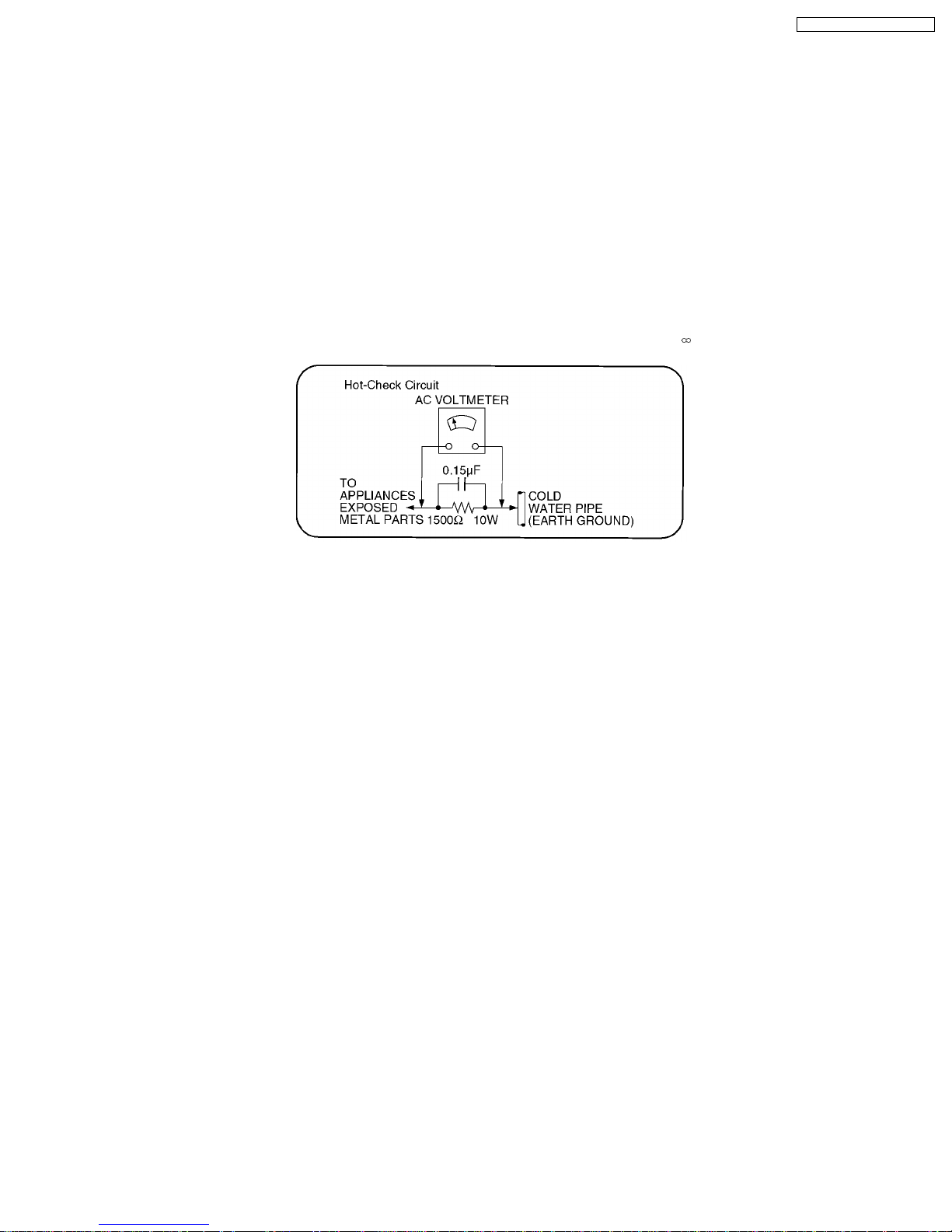
1.1.2. LEAKAGE CURRENT HOT CHECK (See Figure 1.)
1. Plug the AC cord directly into the AC outlet. Do not use an isolation transformer for this check.
2. Connect a 1.5kΩ, 10 watts resistor, in parallel with a 0.15µF capacitors, between each exposed metallic part on the set and a
good earth ground such as a water pipe, as shown in Figure 1.
3. Use an AC voltmeter, with 1000 ohms/volt or more sensitivity, to measure the potential across the resistor.
4. Check each expose d metallic part, and measure the voltage at each point.
5. Reverse the AC plug in the AC outlet and repeat each of the above measurements.
6. The potential at any point should not exceed 0.75 volts RMS. A leakage current tester (Simpson Model 229 or equivalent) may
be used to make the hot checks, leakage current must not exceed 1/2 milliamp. In case a measurement is outside of the limits
specified, there is a possibility of a shock hazard, and the equipment should be repaired and rechecked before it is returned to
the customer.
1.2. Before Repair and Adjustment
Disconnect AC power, discharge Power Supply Capacitors C5700, C5717, C5718, C5742, C5796 through a 10 Ω, 10 W resistor
to ground.
DO NOT SHORT-CIRCUIT DIRECTLY (with a screwdriver blade, for instance), as this may destroy solid state devices.
After repairs are completed, restore power gradually using a variac, to avoid overcurrent.
Current consum ption at AC 120 V, 60 Hz in NO SIGNAL mode volume minimal should be ~ 900 mA.
5

SA-HT640WP / SA-HT640 WPC
1.2.1. Caution for fuse replacement
1.3. Protection Circuitry
The protection circuitry may have operated if either of the following conditions are noticed:
· No sound is heard when the power is turned on.
· Sound stops during a performance.
The function of this circuitry is to prevent circuitry damage if, for example, the positive and negative speaker connection wires are
“shorted”, or if speaker systems with an impedance less than the indicated rated impedance of the amplifier are used.
If this occurs, follow the procedure outlines below:
1. Turn off the power.
2. Determine the cause of the problem and correct it.
3. Turn on the power once again after one minute.
Note:
When the protection circuitry functions, the unit will not operate unless the power is first turned off and then on again.
2 Prevention of Electro Static Discharge (ESD) to
Electrostatically Sensitive (ES) Devices
Some semiconductor (solid state) devices can be damaged easily by static electricity. Such components commonly are called
Electrostatically Sensitive (ES) Devices. Examples of typical ES devices are integrated circuits and some field-effect transistors and
semiconductor "chip" components. The following techniques should be used to help reduce the incidence of component damage
caused by electro static discharge (ESD).
1. Immediately before handling any semiconductor component or semiconductor-equipped assembly, drain off any ESD on your
body by touchin g a known earth ground. Alternatively, obtain and wear a commercially available discharging ESD wrist strap,
which should be removed for potential shock reasons prior to applying power to the unit under test.
2. After removing an electrical assembly equipped with ES devices, place the assembly on a conductive surface such as
aluminum foil, to prevent electrostatic charge buildup or exposure of the assembly.
3. Use only a grounded-tip soldering iron to solder or unsolder ES devices.
4. Use only an anti-static solder removal device. Some solder removal devices not classified as "anti-static (ESD protected)" can
generate electrical charge sufficie nt to damage ES devices.
5. Do not use freon-propelled chemicals. These can generate electrical charges sufficient to damage ES devices.
6. Do not remove a replacement ES device from its protective package until immediately before you are ready to install it. (Most
replacement ES devices are packaged with leads electrically shorted together by conductive foam, aluminum foil or comparable
conductive material).
7. Immediately before removing the protective material from the leads of a replacement ES device, touch the protective material
to the chassis or circuit assembly into which the device will be installed.
Caution
Be sure no power is applied to the chassis or circuit, and observe all other safety precautions.
8. Minimize bodily motions when handling unpackaged replacement ES devices. (Otherwise harmless motion such as the
brushing together of your clothes fabric or the lifting of your foot from a carpeted floor can generate static electricity (ESD)
sufficient to damage an ES device).
6

SA-HT640WP / SA-HT640 WPC
7
SA-HT640WP / SA-HT640 WPC
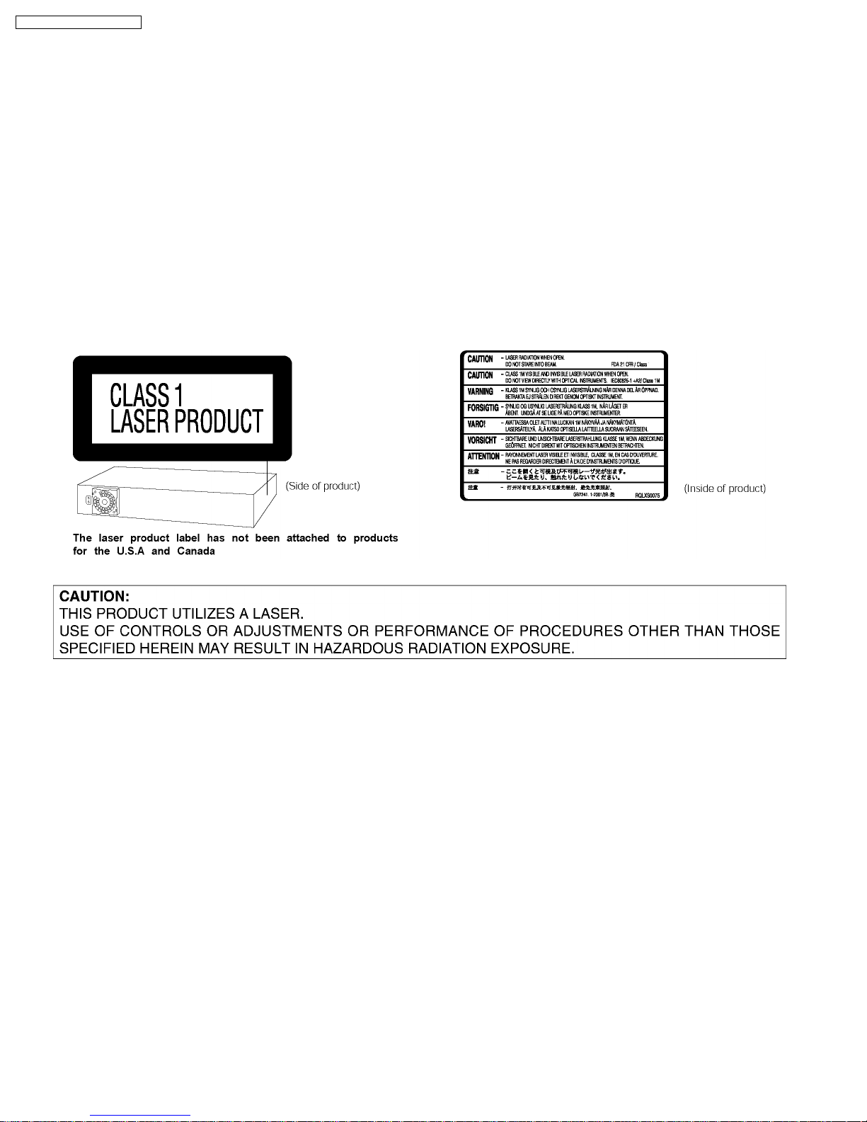
3 Precaution of Laser Diode
CAUTION:
This unit utilizes a class 1 laser.
Invisible laser radiation is emitted from the optical pickup lens.
Wavelength: 662nm(DVD)/785nm(CD).
Maximum output radiation power from pickup: 100µW/VDE
When the unit is turned on:
1. Do not look directly into the pick up lens.
2. Do not use optical instruments to look at the pick up lens.
3. Do not adjust the preset variable resistor on the pickup lens.
4. Do not disassemble the optical pick up unit.
5. If the optical pick up is replaced, use the manufacturer’s specified replacement pick up only.
6. Use of control or adjustments or performance of procedures other than those specified herein may result in hazardous
radiation exposure.
4 About Lead Free Solder (PbF)
Distinction of PbF PCB: PCBs (manufactured) using lead free solder will have a PbF stamp on the PCB.
Caution:
· Pb free solder has a higher melting point than standard solder; Typically the melting point is 50 - 70°F (30 - 40°C) higher.
Please use a high temperature soldering iron. In case of the soldering iron with temperature control, please set it to 700 ±
20°F (370 ± 10°C).
· Pb free solder will tend to splash when heated too high (about 1100°F/ 600°C).
When soldering or unsoldering, please completely remove all of the solder on the pins or solder area, and be sure to heat the
soldering points with the Pb free solder until it melts enough.
8
SA-HT640WP / SA-HT640 WPC
5 Handling Precautions for Traverse Unit
The laser diode in the optical pickup unit may break down due to static electricity of clothes or human body. Special care must be
taken avoid caution to electrostatic breakdown when servicing and handlin g the laser diode.
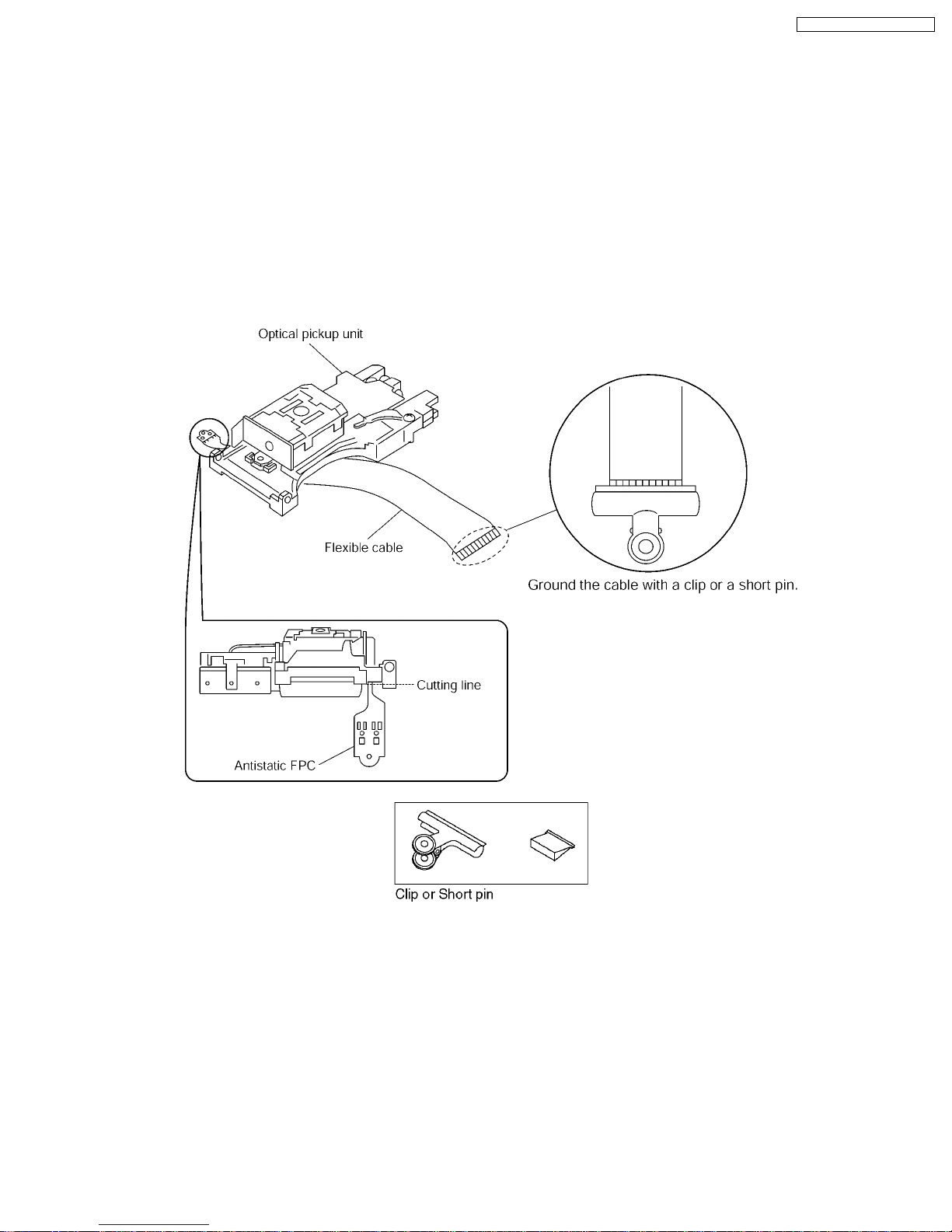
5.1. Cautions to Be Taken in Handling the Optical Pickup Unit
The laser diode in the optical pickup unit may be damaged due to electrostatic discharge generating from clothes or human body.
Special care must be taken avoid caution to electrostatic discharge damage when servicing the laser diode.
1. Do not give a considerable shock to the optical pickup unit as it has an extremely high-precise structure.
2. To prevent the laser diode from the electrostatic discharge damage, the flexible cable of the optical pickup unit removed should
be short-circuited with a short pin or a clip.
3. The flexible cable may be cut off if an excessive force is applied to it. Use caution when handling the flexible cable.
4. The antistatic FPC is connected to the new optical pickup unit. After replacing the optical pickup unit and connecting the flexible
cable, cut off the antistatic FPC.
5.2. Grounding for electrostatic breakdown prevention
Some devices such as the DVD player use the optical pickup (laser diode) and the optical pickup will be damaged by static
electricity in the working environment. Proceed servicing works under the working environment where grounding works is
completed.
5.2.1. Worktable grounding
1. Put a conductive material (sheet) or iron sheet on the area where the optical pickup is placed , and ground the sheet.
5.2.2. Human body grounding
1. Use the anti-static wrist strap to discharge the static electricity form your body.
9

SA-HT640WP / SA-HT640 WPC
10
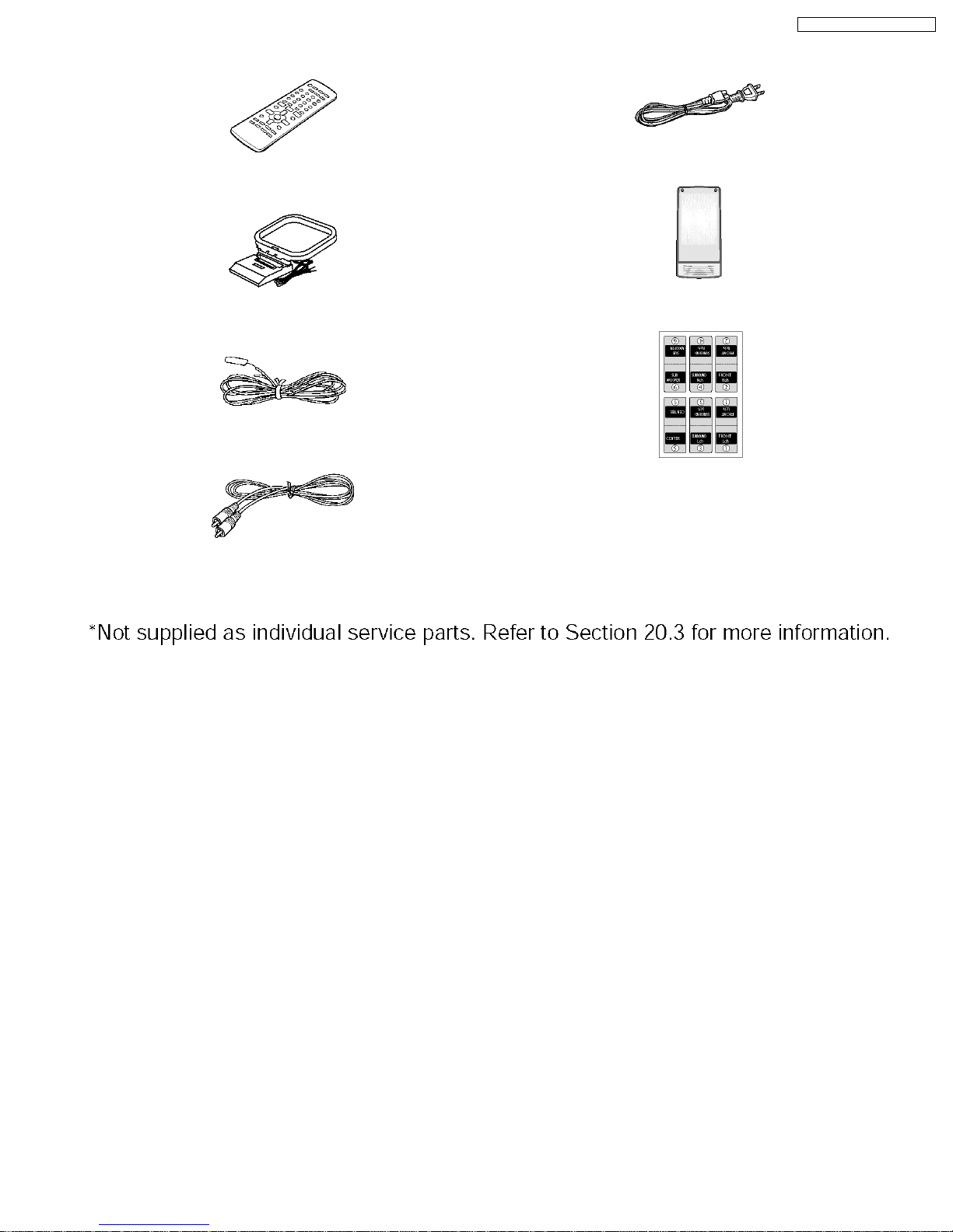
6 Accessories
Remote control
SA-HT640WP / SA-HT640 WPC
AC cord
AM loop antenna
FM indoor antenna
Video Cable
Digital transceiver*
Speaker label
11
SA-HT640WP / SA-HT640 WPC
7 Operation Procedures
7.1. Operating instructions
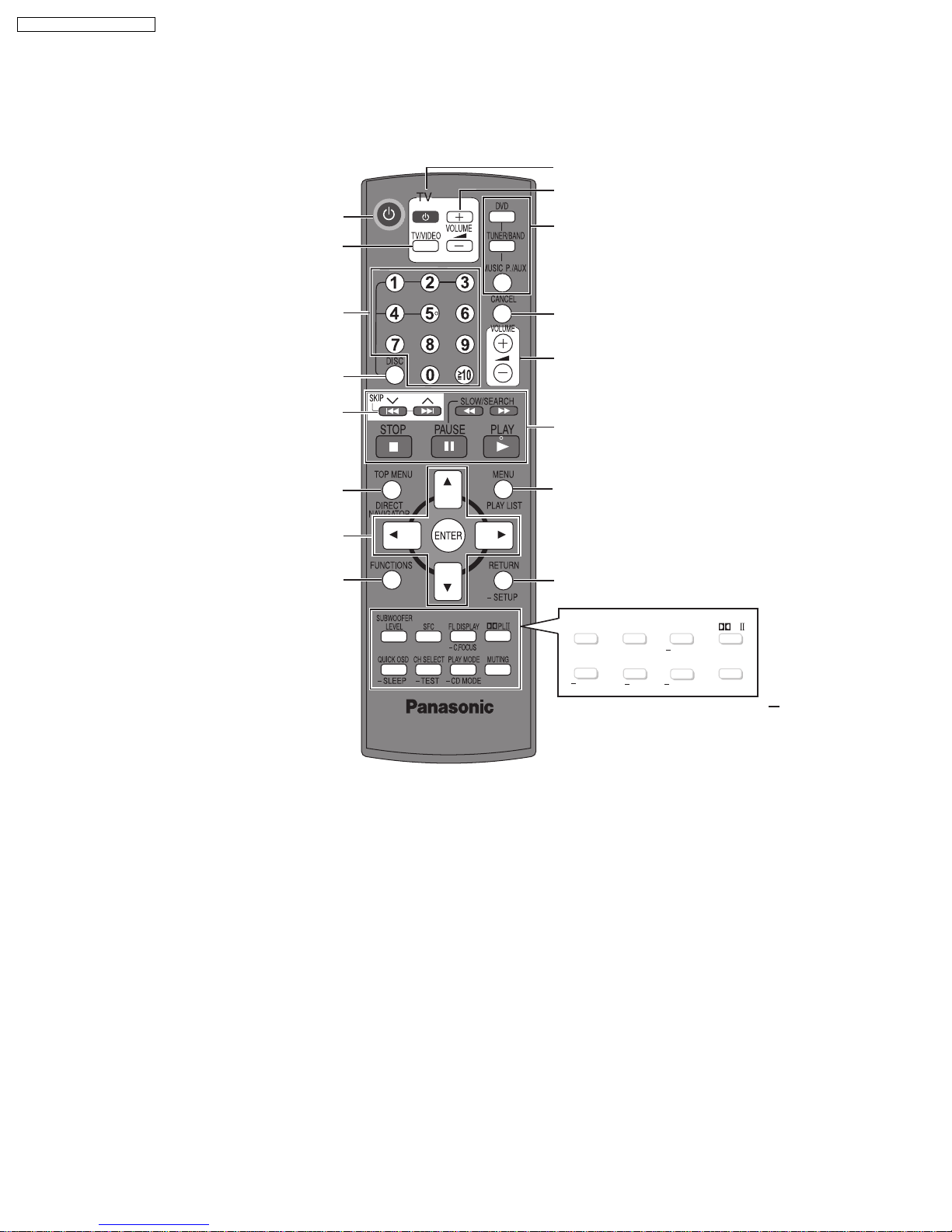
7.1.1. Remote Control Key Buttons Operations
Turn the unit on/off
Change the television's video input mode
Television operations
Adjust the television volume
Select the source
DVD/CD, FM/AM, AUX/FRONT
MUSIC P./REAR MUSIC P.
Select disc's title numbers etc./Enter numbers
Select the disc or show disc information
Select preset radio stations
Show a disc top menu or program list
Frame-by-frame/Select or register menu
items on the television screen
Show on-screen menu
Cancel
Adjust the volume of the main unit
Basic operations for play
Show a disc menu or play list
Return to previous screen or show the setup menu
SUB WOOFER
LEVEL
QUICK OSD
SLEEP
SFC
FL DISPLA
TEST
C. FOCUS
CD MODE
CH SELECT PLAY MODE
To use functions labelled with
PL
Y
MUTING
":
"
Press and hold the button for at least 2 seconds.
12

7.1.2. Main Unit Key Buttons Operations (SA-HT640W)
SA-HT640WP / SA-HT640 WPC
Standby/on switch [POWER
/I]
Press to switch the unit from on to standby mode
or vice versa. In standby mode, the unit is still
consuming a small amount of power.
MUSIC PORT
Connect an external device
SURROUND MUSIC
Equalizing the sound
POWER MUSIC SURROUND
PORT
12345
MUSIC
5 DISC SELECTOR
//
-
5 DISC SELECTOR
Select the disc tray
TUNE MODE FM MODE
Stop playing/Select the tuning mode
Adjust the FM reception condition
/
MEMORY
Play discs/Memorize the
receiving radio stations
,
/ TUNING
Skip or slow-search play/
Select the radio stations
Display
TUNINGTUNING
MEMORYMEMORY
TUNE MODETUNE MODE
FM MODEFM MODE
-
OPEN/CLOSE
Open/Close the disc drawer
DISC EXCHANGE
Open the disc drawer to
exchange the disc in the
play position
OPEN/CLOSE
DISC DISC
SELECTOR
EXCHANGE SKIP
VOLUME
DISC SKIP
Skip to the next disc tray
Phones
C
onnect headphones
VOLUME
Turn up/down the volume
SELECTOR
DVD/CD FM AM AUX FRONT
MUSIC P.
REAR MUSIC P.
Return to DVD/CD
13

SA-HT640WP / SA-HT640 WPC
7.1.3. Wireless Surround Speaker Key Buttons Operations (SB-SA640)
Wireless selector [WIRELESS ON, OFF]
ON
Power indicator
This indicator lights when the unit is
plugged into the AC outlet.
AC IN
WIRELESS
MUSIC PORT
ON
OFF
:Select when enjoying audio from the main unit.
:Select when enjoying audio from MUSIC PORT
OFF
on the surround speaker.
Lighting Ring
The light goes out when the speaker is
MUSIC PORT
Connect an external device
in standby mode.
Note: Refer to original service manua l (Order No. MD0512492C1) for more information of this unit (SB-SA640).
14
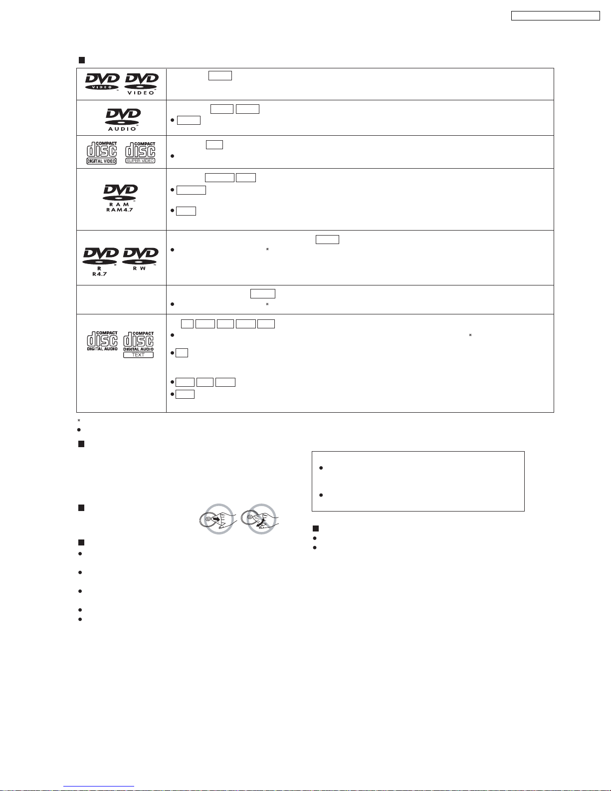
7.2. Disc information
Discs that can be played
DVD-Video
—
DVD-Audio
DVD-V
DVD-V
DVD-A
DVD-V
Some DVD-Audio Discs contain DVD-Video content.
SA-HT640WP / SA-HT640 WPC
Video CD
VCD
Including SVCD (Conforming to IEC62107).
DVD-RAM
DVD-VR
DVD-VR
Recorded with devices using Version 1.1 of the Video Recording Format (a
standard), such as DVD video recorders, DVD video cameras, personal computers, etc.
JPEG
Recorded with Panasonic SD multi cameras or DVD video recorders using the
JPEG
unified video recording
DCF (Design rule for Camera
File System) Standard Version 1.0.
(DVD-Video) (DVD-Video)/
DVD-R
Discs recorded and finalized
(Video) (Video)
—
+R +RW/
Discs recorded and finalized
CD
CD
This unit can play CD-R/RW recorded with the above formats. Close the sessions or finalize
recording.
This unit is compatible with HDCD, but does not support the Peak Extend function (a function which expands the
CD
DVD-RW
DVD-V
JPEGMP3 VCDWMA
DVD-V
on DVD video recorders or DVD video cameras.
on DVD video recorders or DVD video cameras.
dynamic range of high-level signals).
HDCD-encoded CDs sound better because they are encoded with 20 bits, as compared with 16 bits for all other CDs.
JPEGMP3WMA
This unit also plays HighMAT discs.
WMA
This unit does not support Multiple Bit Rate (MBR: an encoding process for audio content that produces an
audio file encoded at several different bit rates).
A process that allows play on compatible equipment.
It may not be possible to play all the above-mentioned discs in some cases due to the type of disc or condition of the recording.
Discs that cannot be played
DVD-RW version 1.0, DVD-ROM, CD-ROM, CDV, CD-G, SACD,
DivX Video Discs and Photo CD, DVD-RAM that cannot be removed
from their cartridge, 2.6-GB and 5.2-GB DVD-RAM, and “Chaoji
VCD” available on the market including CVD, DVCD and SVCD that
do not conform to IEC62107.
To clean discs
Wipe with a damp cloth and then wipe
dry.
Disc handling precautions
Do not attach labels or stickers to discs. This may cause disc
warping, rendering it unusable.
Do not write on the label side with a ball-point pen or other writing
instrument.
Do not u
se record cleaning sprays, benzine, thinner, liquids which
prevent static electricity, or any other solvent.
Do not use scratch-proof protectors or covers.
Do not use the following discs:
– Discs with exposed adhesive from removed stickers or labels
(rented discs, etc).
– Discs that are badly warped or cracked.
– Irregularly shaped discs, such as heart shapes.
Note about using a DualDisc
The digital audio content side of a DualDisc does not meet
the technical specifications of the Compact Disc Digital Audio
(CD-DA) format so playback may not be possible.
Do not use DualDisc in this unit as it may not possible to
insert it correctly and it may get scratched or scraped.
Clean this unit with a soft, dry cloth.
Never use alcohol, paint thinner or benzine to clean this unit.
Before using chemically treated cloth, carefully read the instructions that
came with the cloth.
Do not use commercially available lens cleaners as they may
cause malfunction. Cleaning of the lens is generally not neccessary
although this depends on the operating environment.
Before moving the unit, ensure the disc trays are empty.
Failure to do so will risk severely damaging the disc and the unit.
the disc after
15
SA-HT640WP / SA-HT640 WPC
16
SA-HT640WP / SA-HT640 WPC
8 New Features
· This model is equipped with the digital transmitter and receiver (SB-SA640 ) to enjoy surround sound wirelessly. For more
information on this model, please refer to the original service manual.
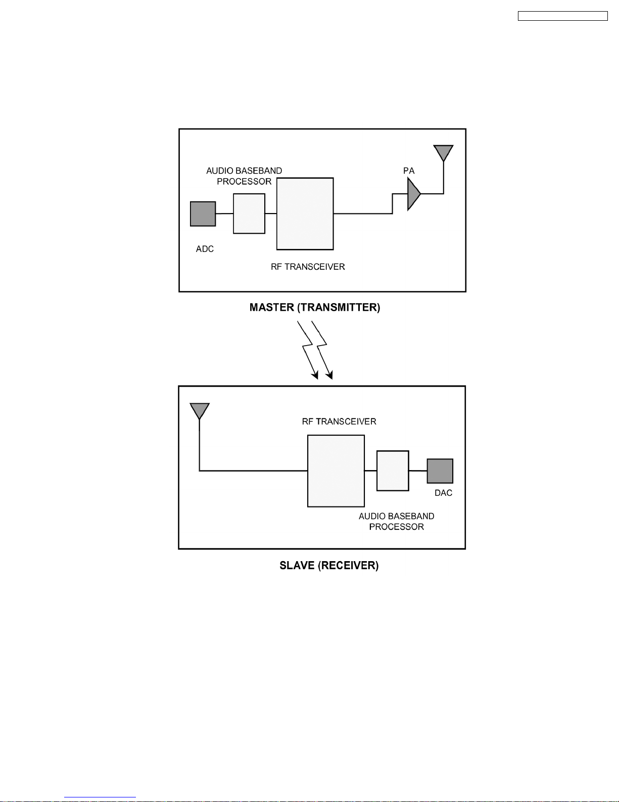
8.1. RF Wireless Audio Transceiver
8.1.1. Block Diagram
8.1.2. Definition
1. ADC : Analog-to-Digital Converter
2. Transceiver : Transmitter-Receiver Device
3. PA : Power Amplifier
4. DAC : Digital-to-Analog Converter
8.1.3. Features
· Crystal Clear CD Quality Stereo Sound
· Highly Robust Forward Error Correction
· 44.1KHz / 48KHz sampling frequency
· Adaptive Frequency Hopping System
· Range (open space) : 100m
17

SA-HT640WP / SA-HT640 WPC
· Low power consumption
· SNR (for left / right channel analog interface) : 80 dB
· THD : 0.2%
· Compact : 40mm x 80mm
18
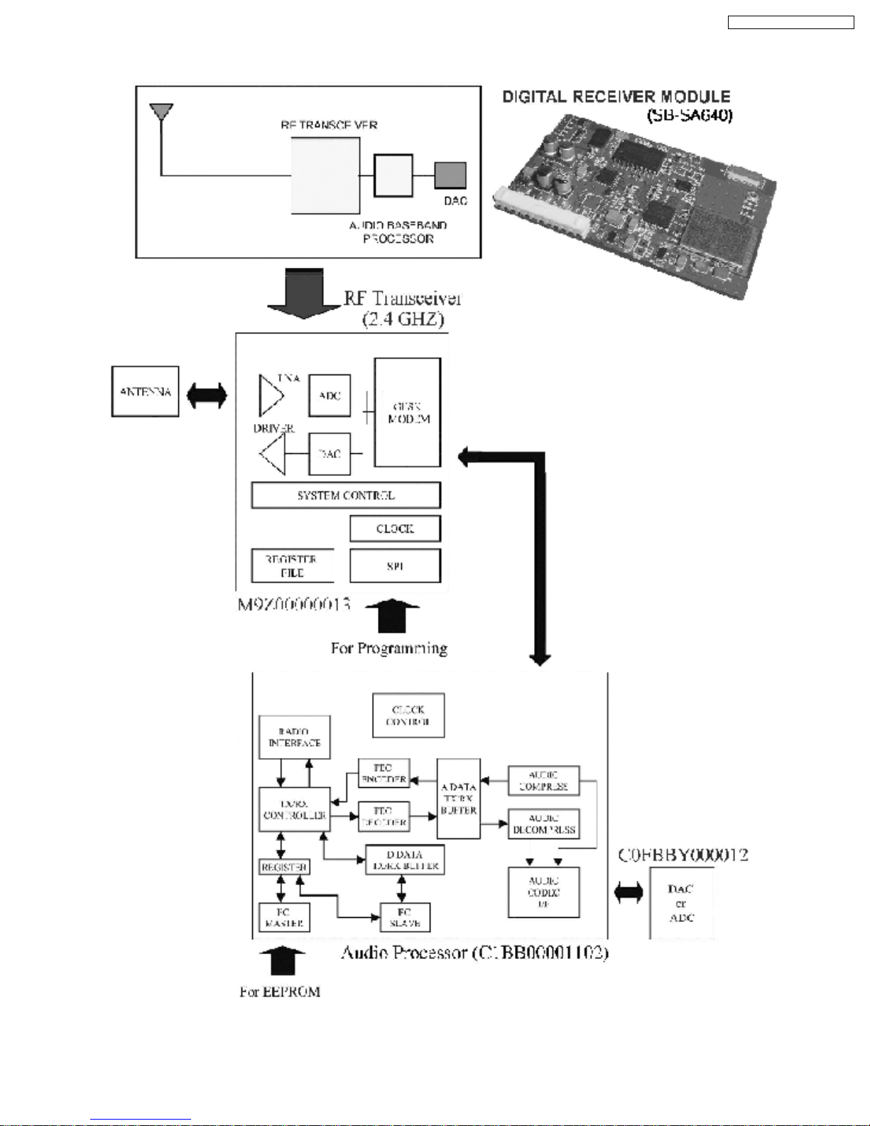
8.2. Detail Block Diagram (Receiver module)
SA-HT640WP / SA-HT640 WPC
19
SA-HT640WP / SA-HT640 WPC
8.2.1. Operation
RF signal transmission and reception:
During the receive process, the radio signal is taken from a pair of balanc ed RF I/O pins that feed into the low noise amplifier (LNA).
Direct I/Q down conversion and on-chip filtering send the processed I/Q data to the analog-to-digital converter before processing
by the GFSK (Gaussian Frequency Shift Keying) demod ulator. Within the demodulator, data detection and timing recovery circuits
convert the data for transfer to an external device. The transmit process operates in a similar fashion in reverse order.
The transmitted signal is GFSK (Gaussian Frequency Shift Keying) modulated data that is amplified on the chip to yield a radiated
output of 0dBm. A power control signal for an external amplifier is provided.
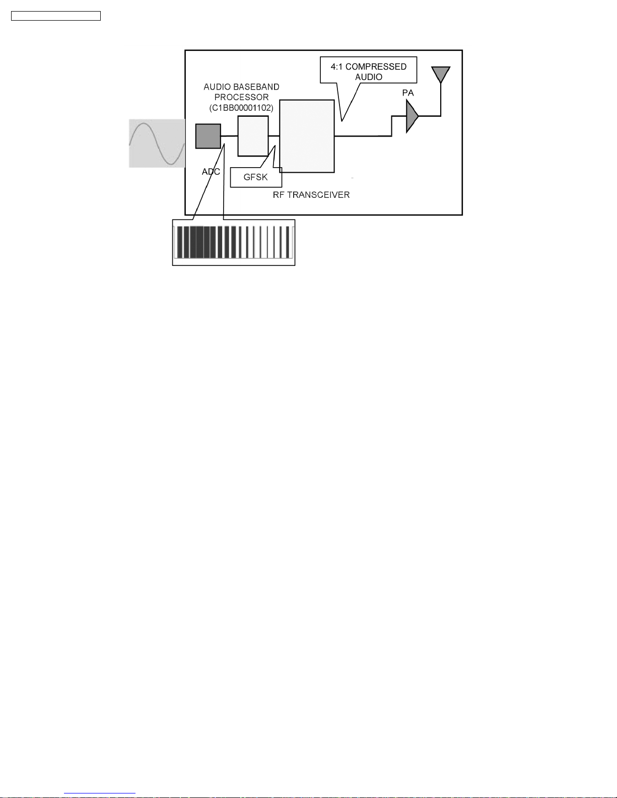
The audio baseband processor (C1BB00001102) is a digital audio processor IC encompassing apt-XTM audio
compress/decompress algorithm for wireless transmission of crystal-clear CD quality audio data.
For digital transmission the analog audio signals are sampled at 48kHz and converted to 1.536Mbps digital data through an
external 16-bit stereo audio codec. The digitized data are apt-XTM 4:1 compressed to 384Kbps stream data for efficient
transmission. Redundancy bits for forward error correction (FEC), synchronization flags, and control signals for time-division
duplexing (TDD) are appen ded to form data frames for error-free transmission.
In the receiver(Slave), synchronization flags and control data are first detected from the input stream. FEC decoder corrects any
errors that may have been introduced during the transmission and produces error-free compressed audio data. The compressed
audio is decompressed into 16-bit stereo PCM audio data through digital signal processing blocks. External audio codec converts
the PCM data to 2-channel (left and right) analog audio signals.
The Tx/Rx controller is in charge of several functions such as radio channel setup, frequency hopping for interference reduction and
generation of control signal for TDD and external RF chip.
In audio mode, the transmitter(Master) can send additional 16Kbps digital data simultaneously with stereo audio data.
How much time delay to transmit audio in wireless?
Audio compression and decompression requires about 3ms. Total time delay can be calculated as follows: Total delay time = audio
compression time + transmitter operating time + receiver operating time + audio decompression time. Total delay time is
approximately 12.2ms.
What is the power consumption?
The 2.4GHz RF module consumes about 45mA (max 65mA) for the transmitter and 55mA (max 71mA) for the receiver. The
EEPROM consumes about 1mA while the baseband IC consumes about 20mA. The total power consumption is 66mA (max 86mA)
for the transmitter and 76mA (max 92mA) for the receiver.
20
SA-HT640WP / SA-HT640 WPC
Does the system support any mode to save power consumption?
Yes, it has POWER SAVING SCAN mode. When the communication link is lost, the slave starts scanning procedure to re-establish
the link. If the slave cannot find the master within a certain amount of time (info stored in EEPROM), the slave automatically goes
into power saving scan mode.
How does the system handle interference from other 2.4GHz RF devices?
It adopts Adaptive Frequency Hoppin g Spread Spectrum (AHSS) technology to avoid interference.
How does the system handle interference from other 2.4GHz RF devices?
The system supports 3 types of Spread Spectrum. These are
1. FHSS - Frequency Hopping Spread Spectrum
2. AHSS - Adaptive Frequency Hopping Spread Spectrum
3. Fixed Channel Mode
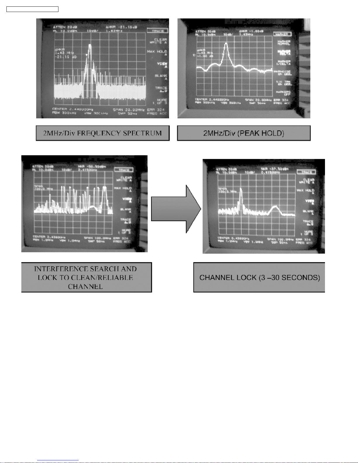
FHSS refers to the conventional 79 channels (or 23 dependent on the country) hopping of Bluetooth. Devices using such hopping
method receives a lot of interference from other devices that use 2.4GHz range frequency such as WLAN and other Bluetooth
devices. FHSS, being built to avoid interfering with other devices, rather interferes a lot with devices that has high output power
using 2.4GHz frequency range and with other FHSS devices. During initialization, system scans 79 channels (or 23) and selects
the clear, non-interfered and reliable channel and starts the communication between master and slave. During the channel link, the
channel becomes unreliable and the error detection from FEC block exceed s the preset error threshold value, the system executes
scanning, as in initialization, and reselects new clear and reliable channel.
FHSS and AHSS can be selected by setting appropriate parameters on the EEPROM.
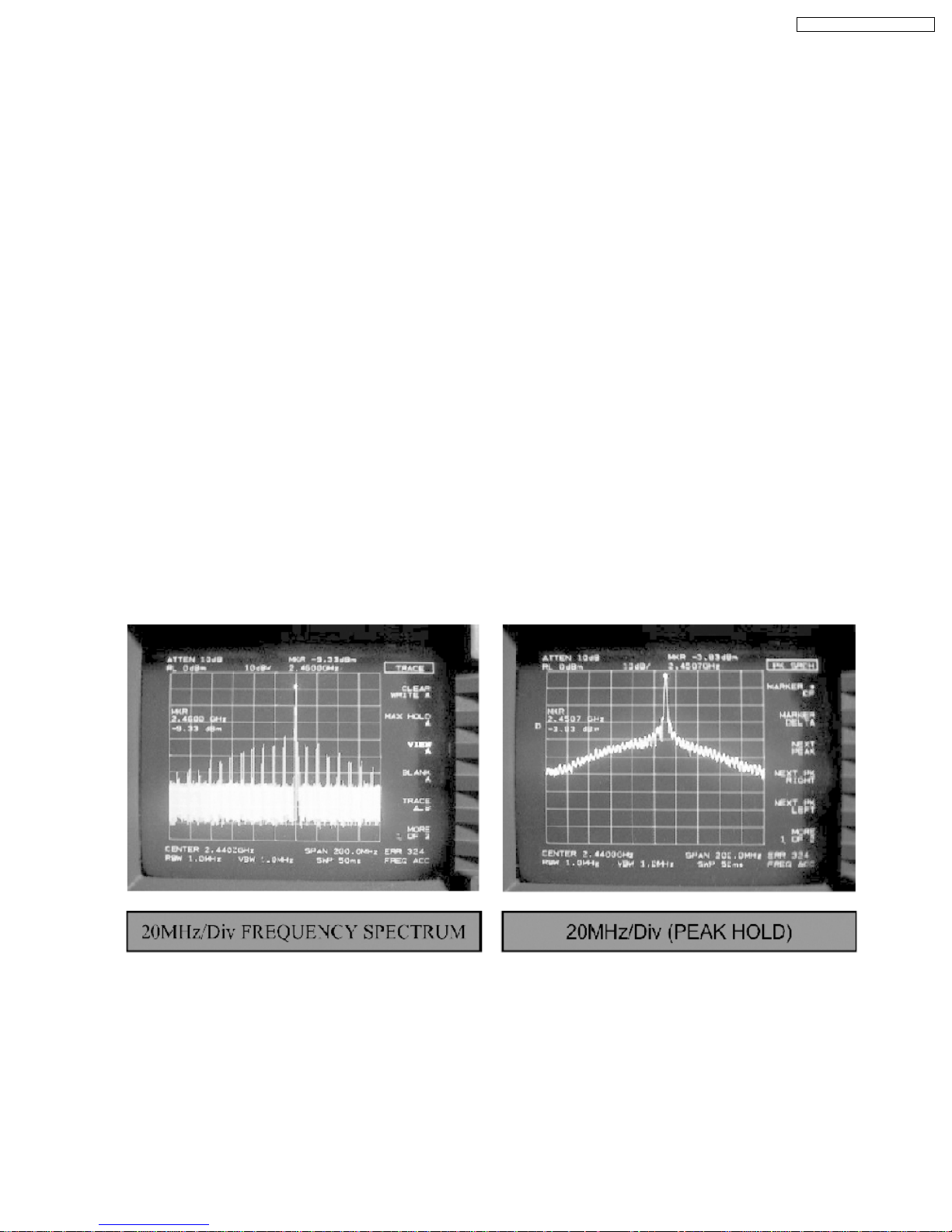
In Fixed Channel mode, 4 frequency levels can be selected (2.410GHz, 2.430GHz, 2.450GHz and 2.470GHz)
Spectrum distribution characteristic of 2.4GHz RF signal
21
SA-HT640WP / SA-HT640 WPC
How can Master or Slave setting be selected? By software or hardware?
It can be selected by external control pin.
How long does it take to transmit single packet?
To establish communication channel properly, hopping frequency and Syncword of each packet should be determined by Device
ID(Identification). Device ID is unique value of each device, master and slaves. Only master and slaves with same Device ID can
communicate each other. Device ID can be set manua lly in case selected master and slaves do not communicate together. This
procedure is *Device ID set*. Device ID set procedure occurs when master and slave devices boot simultaneously with ID_SET=1.
In this procedure, the slave can figure out the Device ID of the master and store it in external EEPROM. When ID_SET is
established, S5G3000 performs ID send/scan to send Device ID of master to slave before general page operation. In normal mode,
communication is accomplished by going into page state directly without ID send/scan.
How can the Master and Slave units be paired to prevent mix-up?
It takes 2.5ms.
22

SA-HT640WP / SA-HT640 WPC
8.3. Class-D Amplifier
8.3.1. How are digital amplifiers different?
A digital amplifier incorporates a switching output stage that operates according to a principle known as pulse width modulation
(PWM). In contrast to the low-frequency control signal used in a conventional analog amplifier output stage, the switching output
stage of a digital amplifier is controlled by a high-frequency digital signal. The high-frequency digital signal is a PWM signal, in
which the music is modulated into a fixed-frequency carrier signal. In a digital amplifier, the modulation process is based on a digital
pulse code modula ted (PCM) representation of the music signal (or other signal that needs amplification) from a CD player, a DVD
player, or some other device.
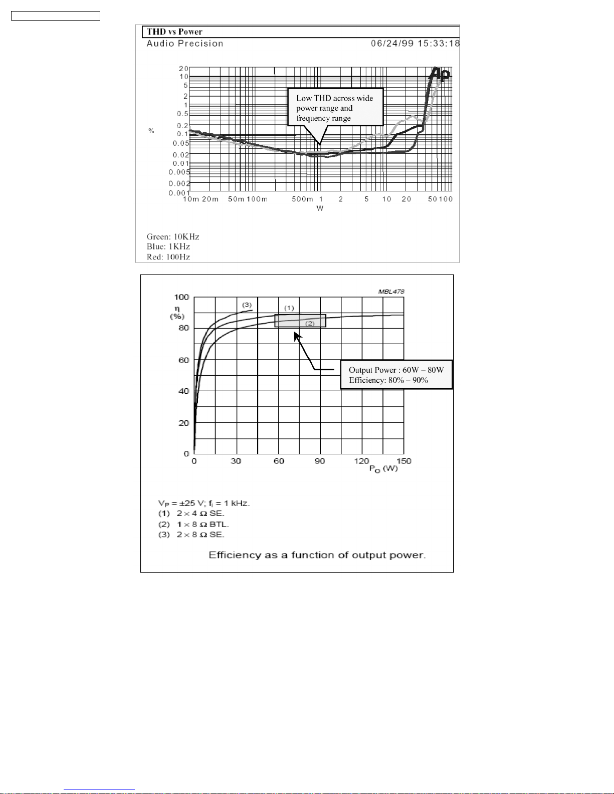
8.3.2. What are the advantages of digital amplification technology?
· High power efficiency, i.e., smaller heat sinks and/or no fan required
· Compact (reduced PCB area)
· Low weight (reduced transformer size)
· Good sound quality (low signal distortion/THD)
8.3.3. Why is the digital amplifier so efficient?
A class-D amplifier is one in which the output transistors are operated as switches. When a transistor is off, the current through it
is zero. When it is on, the voltage across it is small, ideally zero. In each case, the power dissipa tion is very low.
8.3.4. Does the “D” in class-D mean DIGITAL?
No. This is not correct because the operation of the class-D amplifier is based on analog principles. There is no digital coding of
the signal. Before the advent of the class-D amplifier, the standard classes were class-A, class-AB, class-B, and class-C. The “D”
is simply the next letter in the alphabet after “C.” Indeed, the earliest work on class-D amplifiers involved vacuum tubes and can
be traced to the early 1950s.
23
SA-HT640WP / SA-HT640 WPC
8.3.5. What are the potential problems of a Class-D amplifier based system?
The two most common issues of class-D amp system are AM interference and EMI. The switching frequency of class-D ranges
from 300kHz to 450kHz typically 315kHz. The harmonics of such switching frequency will fall into the AM band of 600kHz to
1710kHz. To avoid interfe rence, it is recommende d to have a variable switching frequency adjustment circuit [usually known as
beatproofing in PSG). Systems without AM tuner are not required to have such circuitry.
24
SA-HT640WP / SA-HT640 WPC
Class-D amp systems are basically switching systems. As such, it is prone to EMI. EMI issues can be rectified through proper
grounding techniques and proper components layout. It is quite common to see ferrite beads, capacitors and inductors on these
systems.
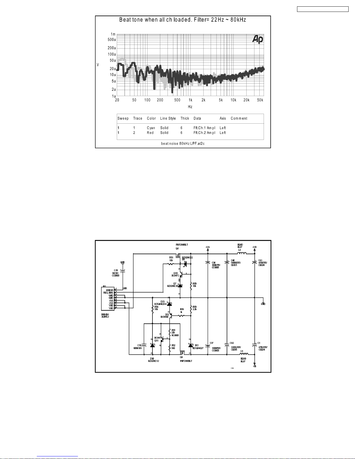
Another issue would be interchannel modulation. This problem would only arise if each channel is using different switching
frequency. It would create an amplified “beat” that can be heard from speakers.
8.3.6. Other issues should we be aware of ?
The class-D amplifier IC is limited to only +/- 30volts power supply. This system uses a linear power source to supply power to the
module. These linear power supplies are unregulated (i.e. voltage is not fixed). Therefore we have to implement a voltage limiter
circuit that would limit the maximum voltage of +/-27volts. It is also imperative that the power supply voltages are almost balanced.
Also, the class-D amplifier IC is configured as single-ended connection. It means one of the outputs is a signal while the other is
connected to ground. With this configuration, this Class D amplifiers will deliver energy back to the power supply . We refer to this
phenomenon as “Supply pumping effect”. Supply pumping effect is more evident on very low frequencies. It is recommended to
have enough buffer on the supply rails to limit the supply pumping effect. It is also advised not to use any type of speakers for
testing. There is an output filter that needs to be matched with the intended speaker. A normal resistive load may be used.
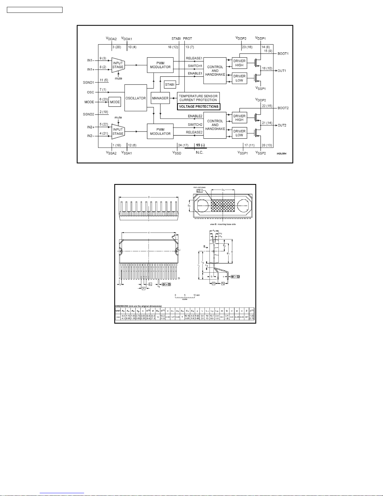
8.3.7. Actual Class-D amplifier IC information
Part number: C1BA00000407 (TDA8920BJ)
25
SA-HT640WP / SA-HT640 WPC
Block diagram:
IC Package Information
Soldering Information
Wave Soldering/Dipping: The maximum permissible temperature of the solder is 260 ーC; solder at this temperature must not be in
contact with the joints for more than 5 seconds. The total contact time of successive solder waves must not exceed 5 seconds.
Manual Soldering: If the temperature of the soldering iron bit is less than 300 ーC it may remain in contact for up to 10 seconds. If
the bit temperature is between 300 and 400 ーC, contact may be up to 5 seconds.
26
9 Self-Diagnosis and special mode setting
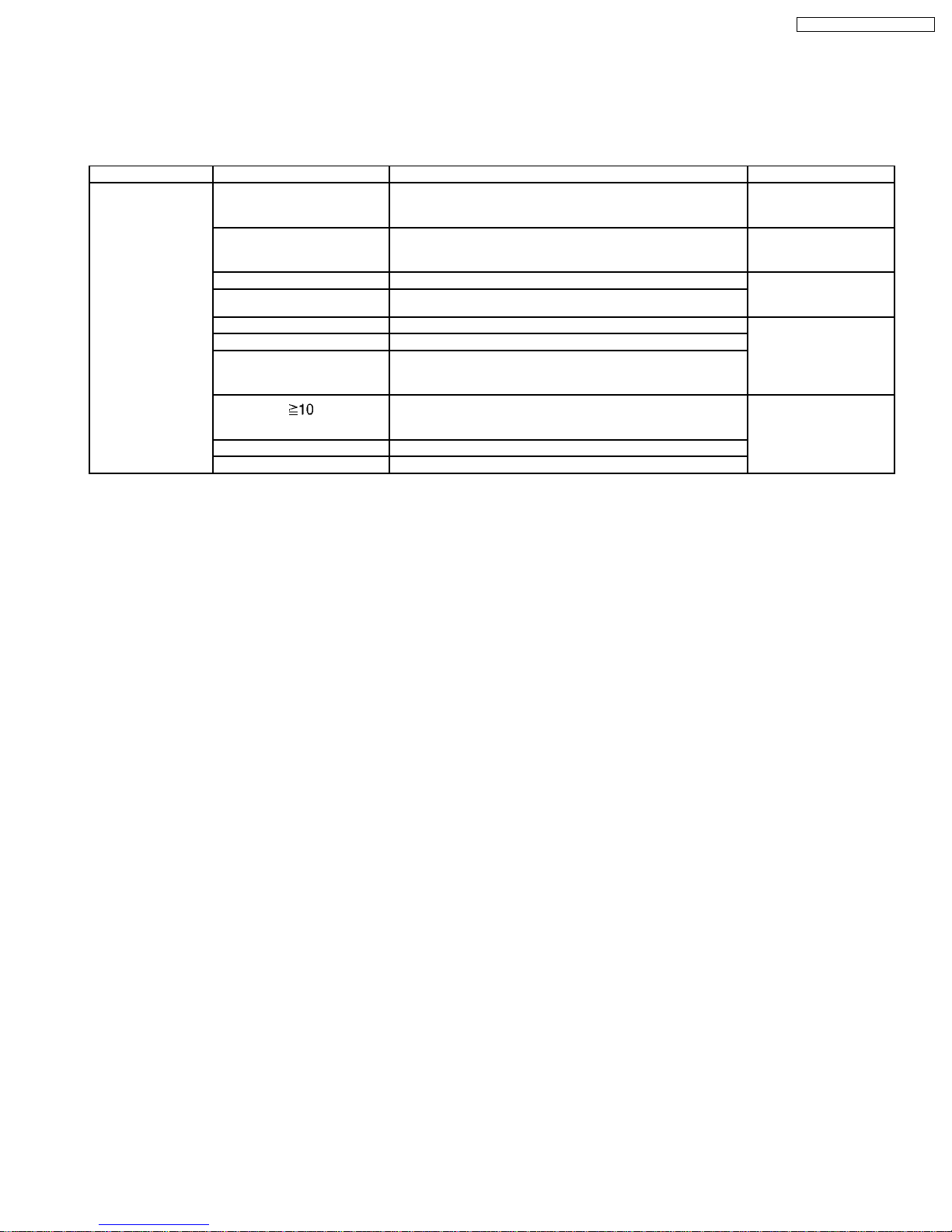
9.1. Service Mode Summary Table
The service modes can be activated by pressing various button combination on the player and remote control unit.
Below is the summary of major checking:
Player buttons Remote control unit buttons Application Note
STOP 0 Error code display (Refer to the section,
5 Jitter checking Refer to the section “9.2
6 Region display and mode (Refer to the section “9.2
7 Micro-processor firmware version check
FUNCTIONS DVD laser drive current check Refer to the section
3 CD laser drive current check
PAUSE Writing of laser drive current value after replacement of optical
pickup (Do use this function only when optical pickup is
replaced.)
Initialization of the player (factory setting is restored.)
Used after replacement of micro-computer, FLASH ROM IC,
EEPROM.
8 DVD HDMI Module firmware version check
ENTER DVD Module Reset.
“9.3 DVD Self Diagnostic
Function-Error Code”).
Service Mode Table 1”
for more information).
Service Mode Table 1 for
more information”).
“9.2.1. Optical Pick-up
Self-Diagnosis”.
Refer to the section “9.2
Service Mode Table 1”
for more information).
SA-HT640WP / SA-HT640 WPC
9.2. Service Mode Table 1
By pressing various button combin ations on the player and remote control unit can activate the various service modes for checking.
Special Note:
Due to the limitations of the no. characters that can be shown on FL Display, the “FL Display” button on the remote control unit
is used to show the following page. (Display 1/Display 2).
27
SA-HT640WP / SA-HT640 WPC
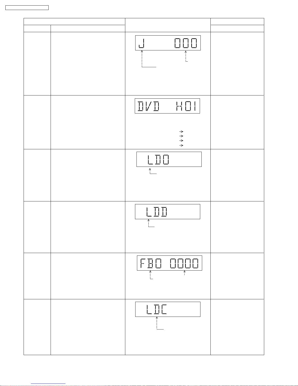
Mode Name
Jitter check
Error code
check
Initial setting
of laser drive
current
DVD laser
drive current
measurement
ADSC internal
RAM data
check
CD laser drive
current
measurement
Item
Description
Jitter check
Jitter rate is measured and displayed.
Measurement is repeatedly done in
the cycle of one second. Read error
counter starts from zero upon mode
setting. When target block data failed
to be read out, the counter advances
by one increment. When the failure is
caused by minor error, it may be
corrected when retried to enable
successful reading. In this case, the
counter advances by one. When the
error persists even after retry, the
counter may jump by two or more.
Error code check
The latest error code stored in the
EEPROM IC is displayed.
Initial setting of laser drive current.
Initial current value for each of DVD
laser and CD laser is separately saved
in the EEPROM IC.
DVD laser drive current measurement
·DVD laser drive current is measured
and the result is displayed together
with the initial value stored in the
EEPROM IC.
After the measurement, DVD laser
emission is kept on. It is turned off
when POWER key is switched off. (It
is also turned off when POWER button
on the player is switched off.)
ADSC internal RAM data check
·ADSC internal RAM data is read out
and displayed.
CD laser drive current measurement
CD laser drive current is measured
and the result is displayed together
with the initial value stored in the
EEPROM IC.
After the measurement, CD laser
emission is kept on. It is turned off
when POWER key is switched off. (It
is also turned off when POWER button
on the player is switched off.)
FL Display
Jitter rate
Jitter check mode
Jitter rate is shown in decimal notation to
one place of decimal.
Focus drive value is shown in hexadecimal
notation.
Error code (play_err) is expressed in the
following convention.
Error code = 0 x DAXX is expressed: DVDnn UXX
Error code = 0 x DBXX is expressed: DVDnn HXX
Error code = 0 x DXXX is expressed: DVDnn FXXX
Error code = 0 x 0000 is expressed: DVDnn F--* "xx" denotes the error code
Laser current measurement
mode
The value denotes the current in decimal
notation. The above example shows the
initial current is 34mA and 28mA for DVD
laser and CD laser respectively when the
laser is switched on.
DVD laser current
measurement mode
The value denotes the current in decimal
notation.
The above example shows the initial current
is 34mA and the measured value is 32mA.
Address
RAM data for
specified address
The value is shown in hexadecimal
notation. The above example shows the
data in ADSC address OFAh is 6901h.
CD laser current
measurement mode
The value denotes the current in decimal
notation.
The above example shows the initial current
is 28mA and the measured value is 26mA.
Key Operation
Front Key
In STOP (no disc) mode,
press STOP button on the
player, and "5" button on
the remote control unit.
Press STOP or OPEN
button to exit.
Press "FL Display" button on
remote control unit for next
page (FL Display).
In STOP (no disc) mode,
press STOP button on the
player, and "0" button on the
remote control unit. * With
pointing of cursor up and
down on display.
Cancelled automatically
5 seconds later.
To exit, press [POWER]
button on main unit or
remote control.
In STOP (no disc) mode,
press STOP button on the
player, and PAUSE button
on the remote control unit.
Cancelled automatically
5 seconds later.
Press "FL Display" button on
remote control unit for next
page (FL Display) on values
of laser drive current.
In STOP (no disc) mode,
press STOP button on the
player, and FUNCTIONS
button on the remote
control unit.
Cancelled automatically
5 seconds later.
Press "FL Display" button on
remote control unit for next
page (FL Display) on values
of dvd drive current.
In STOP (no disc) mode,
press STOP button on the
player, and "1" button on
the remote control unit.
Press STOP or PLAY
button.
In STOP (no disc) mode,
press STOP button on the
player, and "3" button on
the remote control unit.
Cancelled automatically
5 seconds later.
Press "FL Display" button on
remote control unit for next
page. (FL Display)
28
SA-HT640WP / SA-HT640 WPC
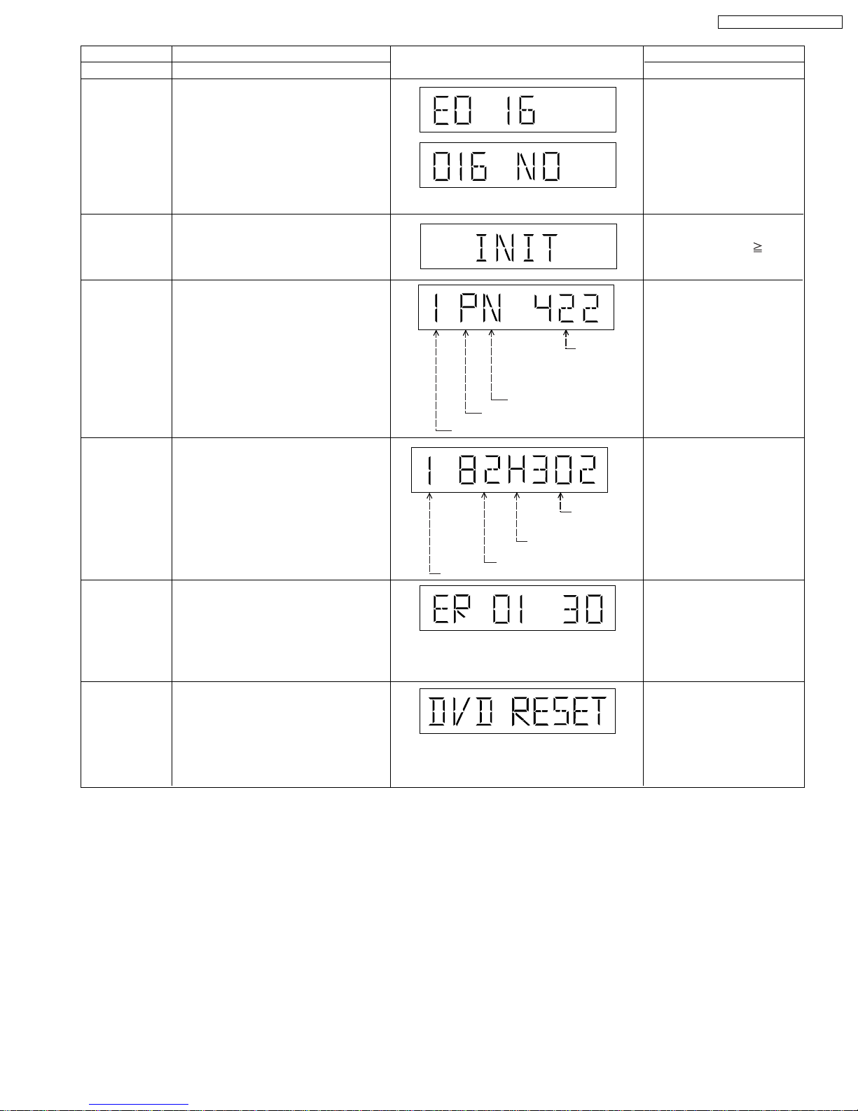
Micro-processor
firmware version
display &
EEPROM
checksum
display.
Initialization
Region display
DVD (HDMI)
module
firmware
version display
Communication
error display
DVD Module
Reset
Item
DescriptionMode Name
Micro-processor firmware version
display & EEPROM checksum display.
Initialization
User settings are cancelled and player
is initialized to factory setting.
Region display & mode
DVD (HDMI) module
firmware version is displayed on the
FL Display.
Displays frequency of communication
errors between system control IC and
mechanism control IC during DVD
module.
To reset DVD Module. (After
initialisation) Refer to Section 9.5.3 for
more information.
N: noPAL / P: PAL
Region No.
Region
FL Display
N: NTSC / 6: PAL60
Destination
System controller
generation
Panel
controller
jumper
information
System
controller
version
Key Operation
Front Key
In STOP (no disc)
mode, press STOP button
on the player, and "7"
button on the remote
control unit.
Cancelled automatically
5 seconds later.
Press "FL Display" button on
remote control unit for next
page. (FL Display)
In STOP (no disc)
mode, press STOP button
on the player , and
10
button on the remote
control unit.
In STOP (no disc)
mode, press STOP button
on the player, and "6"
button on the remote
control unit.
Cancelled automatically
5 seconds later.
In STOP (no disc)
mode, press STOP button
on the player, and "8"
button on the remote
control unit.
Cancelled automatically
5 seconds later.
In STOP (no disc)
mode, press STOP button
on the player, and "MENU"
button on the remote
control unit.
Cancelled automatically
5 seconds later.
While in initialization
mode, press & hold STOP
button on player follow by
"ENTER" button on remote
control unit.
Cancelled automatically
5 seconds later.
29
SA-HT640WP / SA-HT640 WPC
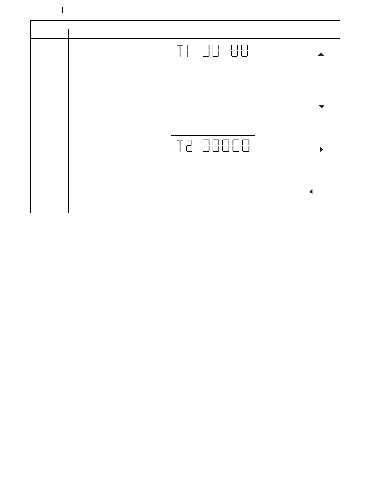
Mode Name
Timer 1 check
Timer 1 reset
Timer 2 check
Timer 2 reset
Item
Description
Timer 1 check
Laser operation timer Operation time is
measured separately for DVD laser
and CD laser.
Press "FL Display" button for next
page of FL Display
Timer 1 reset
Laser operation timer Operation time
of both DVD laser and CD laser is
reset all at once.
Timer 2 check
Spindle motor operation timer
Press "FL Display" button for next
page of FL Display
Timer 2 reset
Spindle motor operation timer
Press "FL Display" button for next
page of FL Display
FL Display
Shown to the left is DVD laser time, and to
the right CD laser time.
Time is shown in 4 digits of decimal notation
in a unit of 10 hours.
"0000" will follow "9999".
T1–0000/0000 (display1/display2)
Time is shown in 5 digits of decimal notation in
a unit of 10 hours.
"00000" will follow "99999".
T2–00000
Key Operation
Front Key
In STOP (no disc)
mode, press STOP button
on the player, and " "
button on the remote
control unit.
Cancelled automatically
5 seconds later.
While displaying Timer 1
data, press STOP button
on the player, and " "
button on the remote
control unit.
Cancelled automatically
5 seconds later.
In STOP (no disc)
mode, press STOP button
on the player, and " "
button on the remote
control unit.
Cancelled automatically
5 seconds later.
While displaying Timer 2
data, press STOP button on
the player, and " " button
on the remote control unit.
Cancelled automatically
5 seconds later.
9.2.1. Optical Pick-up Self-Diagnosis
The optical pickup self-diagnosis function and tilt adjustment check function have been included in this unit. When repairing, use
the following procedure for effective self-diagnosis and tilt adjustment. Be sure to use the self-diagnosis function before replacing
the optical pickup when "NO DISC" is displayed. As a guideline, you should replace the optical pickup when the value of the laser
drive current is more than 10 (Difference between actual and preset value).
Note:
Press the power button to turn on the power, and check the value within three minutes before the unit warms up. (Otherwise,
the result will be incorrect.)
30
 Loading...