

Page 1
PSG1202004CE
Speaker System
Model No. SB-AKX34PN
Product Color : (K)... Black Type
TABLE OF CONTENTS
1 Service Navigation----------------------------------------------- 2
1.1. System Information (SB-AKX34PN-K)--------------- 2
1.2. Front Speakers (SB-AKX34PN-K) -------------------- 2
2 Specifications ----------------------------------------------------- 3
3 Disassembly and Assembly Instructions ---------------- 4
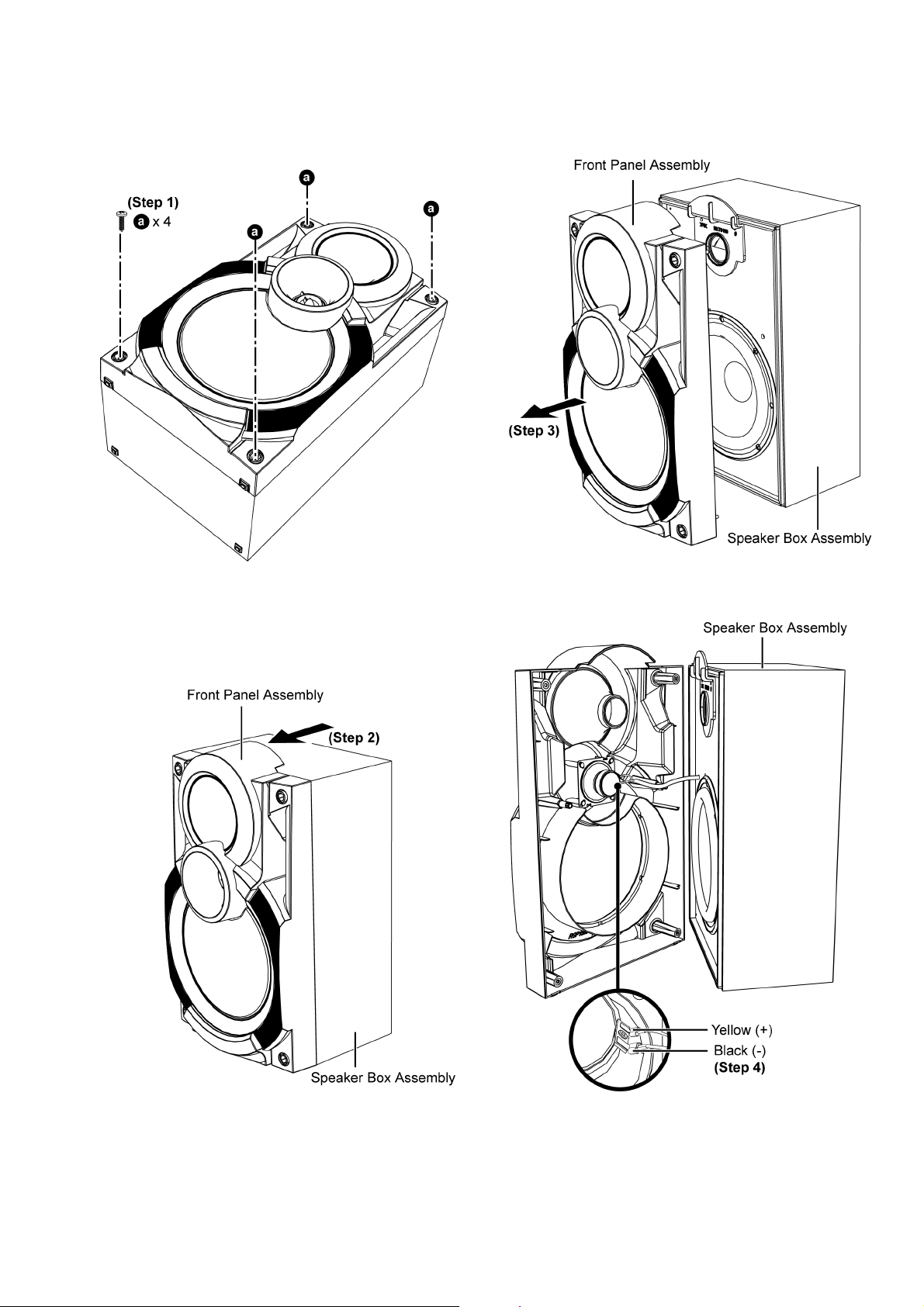
3.1. Disassembly of Front Panel Assembly-------------- -5
3.2. Disassembly of Tweeter Speaker (SP1) ------------- 6
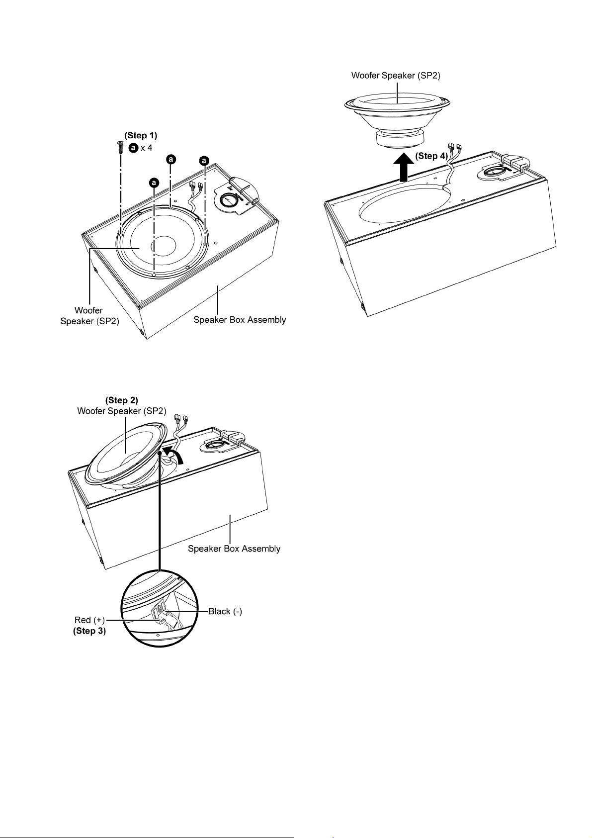
3.3. Disassembly of Woofer Speaker (SP2)-------------- 7
3.4. Replacement of Speaker Connector Housing------ 8
4 Wiring Connection Diagram ---------------------------------- 9
5 Exploded View and Replacement Parts List -----------11
5.1. Cabinet Parts Location ---------------------------------11
5.2. Packaging --------------------------------------------------12
5.3. Replacement Parts List ---------------------------------13
PAGE PAGE
© Panasonic Corporation 2012, All rights reserved.
Unauthorized copying and distribution is a violation of
law.
Page 2

1 Service Navigation
1.1. System Information (SB-AKX34PN-K)
SB-AKX34PN-K is use for the following main models:
SC-AKX34PH-K
SC-AKX34PN-K
SC-AKX34PR-K
1.2. Front Speakers (SB-AKX34PN-K)
The illustrations for the speakers will be described in this manual.
• Disassembly and Assembly Instructions
• Wiring Connection Diagram
• Exploded View
• Replacement Parts List
2
Page 3

2 Specifications
Front Speakers (SB-AKX34PN-K)
Type 2 way, 2 speaker system (Bass reflex)
Speaker unit(s)
Woofer 20 cm Cone type
Tweeter 6 cm Cone type
Impedance 4Ω
Output sound pressure 87 dB/W (1 m)
Frequency range 50 Hz to 21 kHz (-16 dB)
75 Hz to 20 kHz (-10 dB)
Dimensions (W x H x D) 250 mm x 429 mm x 226 mm
Mass 4 kg
Notes:
1. Specifications are subject to change without notice. Mass and
dimensions are approximate.
2. Total harmonic distortion is measured by the digital spectrum analyzer.
3
Page 4

3 Disassembly and Assembly Instructions
Caution Note:
• This section describes procedures for checking the operation and replacing the main components.
• For reassembly after operation checks or replacement, reverse the respective procedures.
• Special reassembly procedures are described only when required.
• Before carrying out the disassembly process, please ensure all the safety precautions & procedures are followed.
• During the disassembly and/or assembly process, please handle with care as there may be cha ssis components with sharp
edges.
• During replacement of component parts, please refer to the section of “Replacement Parts List” as described in the service manual.
• Select items from the following indexes when disassembly or replacement are required.
Front Speakers (SB-AKX34PN-K)
• Disassembly of Front Panel Assembly
• Disassembly of Tweeter Speaker (SP1)
• Disassembly of Woofer Speaker (SP2)
4
Page 5
3.1. Disassembly of Front Panel Assembly
Step 1 : Remove 4 screws.
Step 3 : Detach the Front Panel Assembly slightly as arrow
shown.
Caution : Do not exert strong force as it may damage the
wiring within.
Step 2 : Slightly push the Front Panel Assembly as arrow
shown.
Caution : Do not exert strong force as it may damage the
Front Panel Assembly.
Step 4 : Detach the yellow (+) and black (-) speaker wires.
5
Page 6
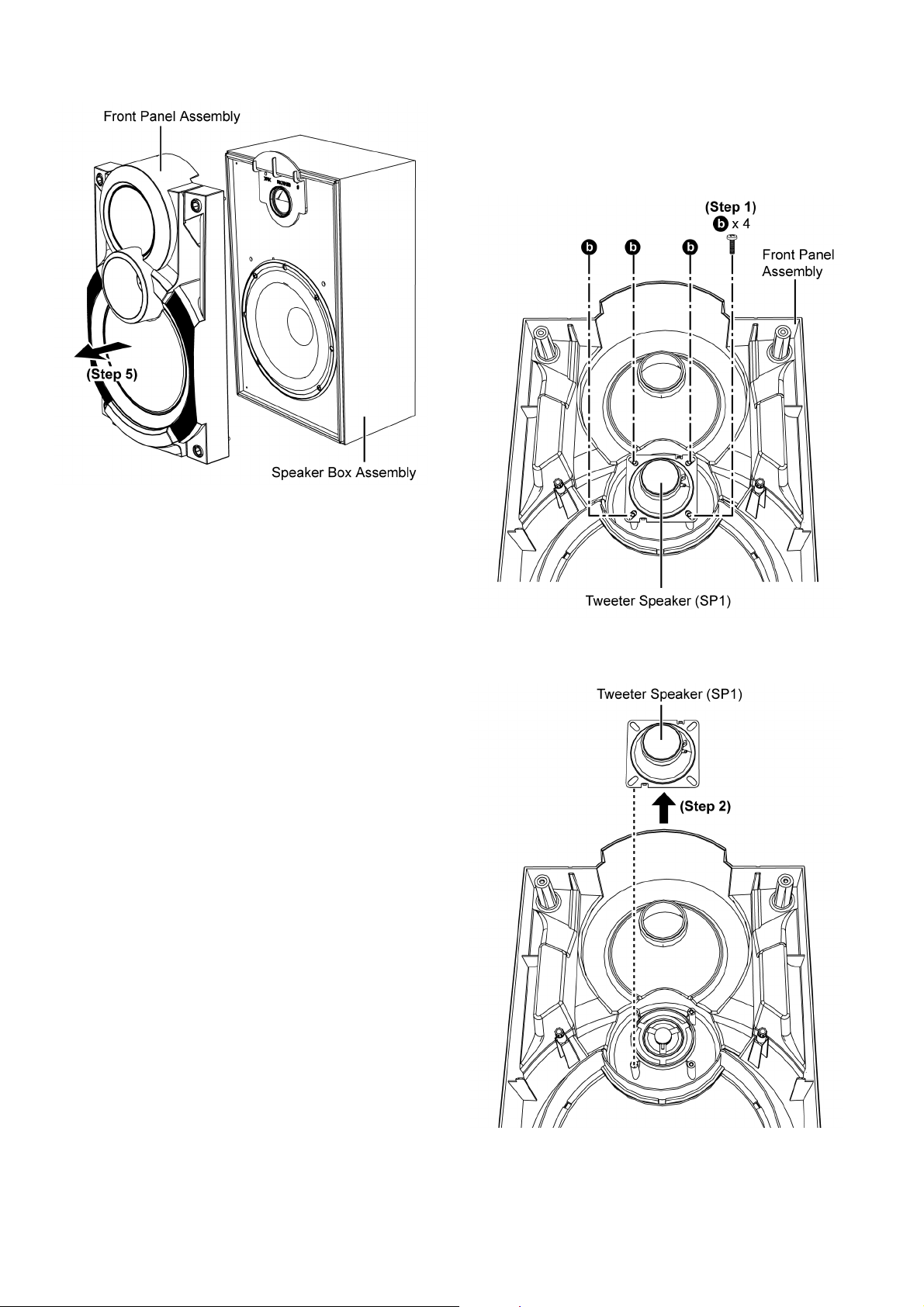
Step 5 : Remove the Front Panel Assembly.
3.2. Disassembly of Tweeter Speaker (SP1)
• Refer to “Disassembly of Front Panel Assembly”
Step 1 : Remove 4 screws.
Step 2 : Remove the Tweeter Speaker (SP1).
6
Page 7
3.3. Disassembly of Woofer Speaker (SP2)
• Refer to “Disassembly of Front Panel Assembly”
Step 1 : Remove 4 screws.
Step 4 : Remove the Woofer Speaker (SP2).
Step 2 : Slightly lift up Woofer Speake r (SP2) as shown.
Step 3 : Detach the red (+) and black (-) speaker wires.
7
Page 8
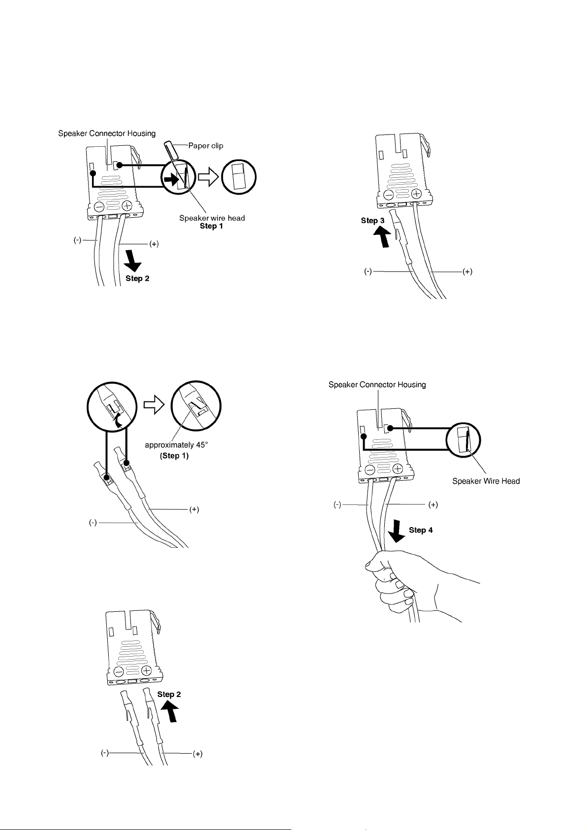
3.4. Replacement of Speaker Connector Housing
3.4.1. Disassembly
Step 1: Use a paper clip push the Speaker Wire head until it
hide inside the Speaker Connector Housing.
Step 2: Pull out the (+) and (-) speaker wire.
Step 3: Insert the (-) speaker wire into the (-) hole of the
speaker connector housing.
Note: Push in the speaker wire until hear the “click” sound.
3.4.2. Assembly
Cautions: Follow the following procedure during assemble.
Step 1: Slightly push up the s peaker wire head approximately
45° as shown.
Step 2: Insert the (+) speaker wire into the (+) hole of the
Speaker Connector Housing.
Note: Push in the speaker wire until hear the “click” sound.
Step 4 : Pull both speaker wires gently to ensure they lock-in
firmly.
Note: Repeat step1 to 3 if the speaker wires come out.
8
Page 9
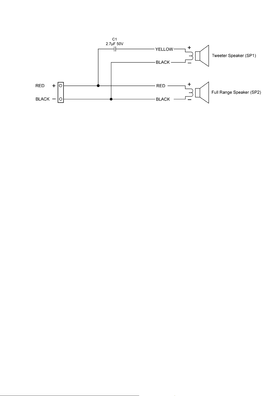
4 Wiring Connection Diagram
9
Page 10

10
Page 11
SP2
SP1
7
7
7
7
6
6
6
6
6
6
6
6
5
4
4
4
4
3
2-1
2
1
a
c
d
c
d
b
a
b
1
2
3
4
5
6
7
8
9
A
B
C
D
E
F
G
H
10 11 12 13
SB-AKX34PN-K
CABINET DRAWINGS
5 Exploded View and Replacement Parts List
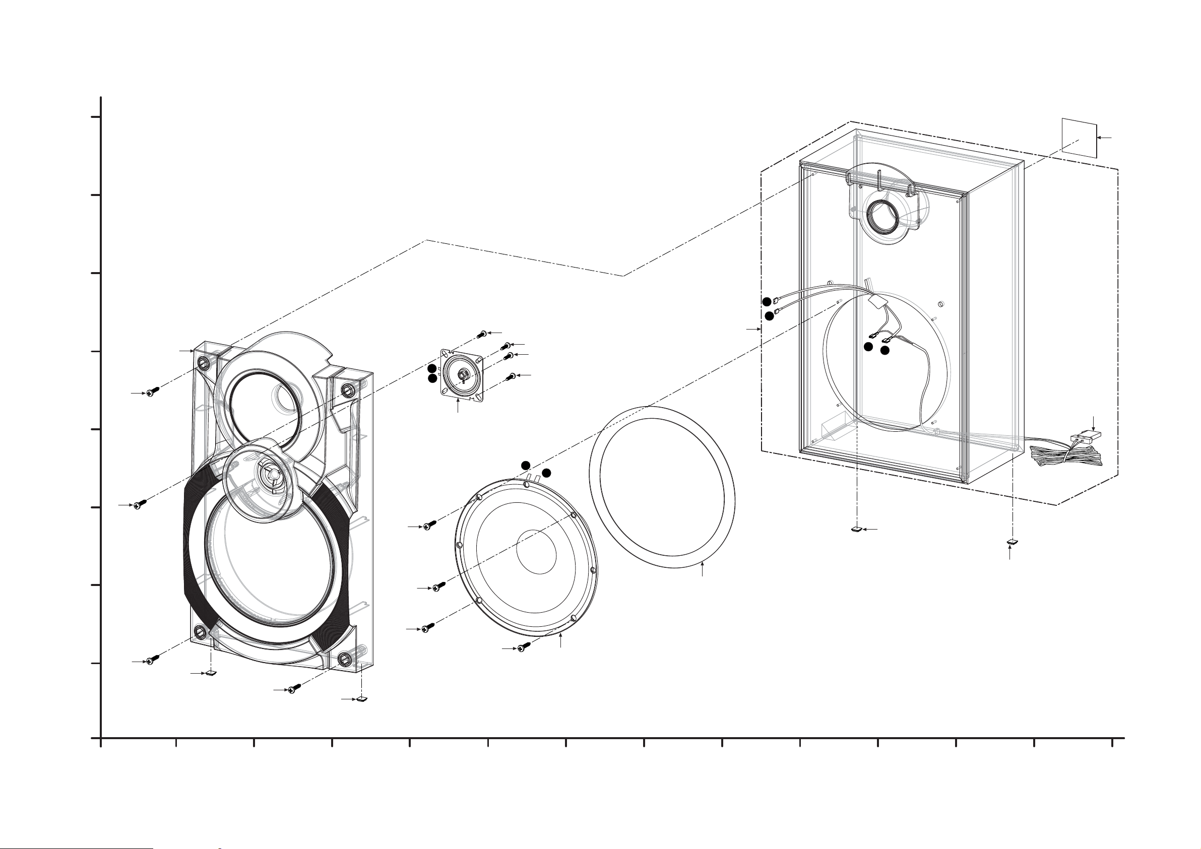
5.1. Cabinet Parts Location
11
Page 12
SB-AKX34PN
SB-AKX34PN
P2
P2
*P1
*P1
1
2
3
4
5
6
7
8
9
A
B
C
D
E
F
G
H
10 11 12 13
SB-AKX34PN-K
FOR SC-AKX34
PACKAGING DRAWINGS
*P1
POLYFOAM (TOP)
POLYFOAM (BOTTOM)
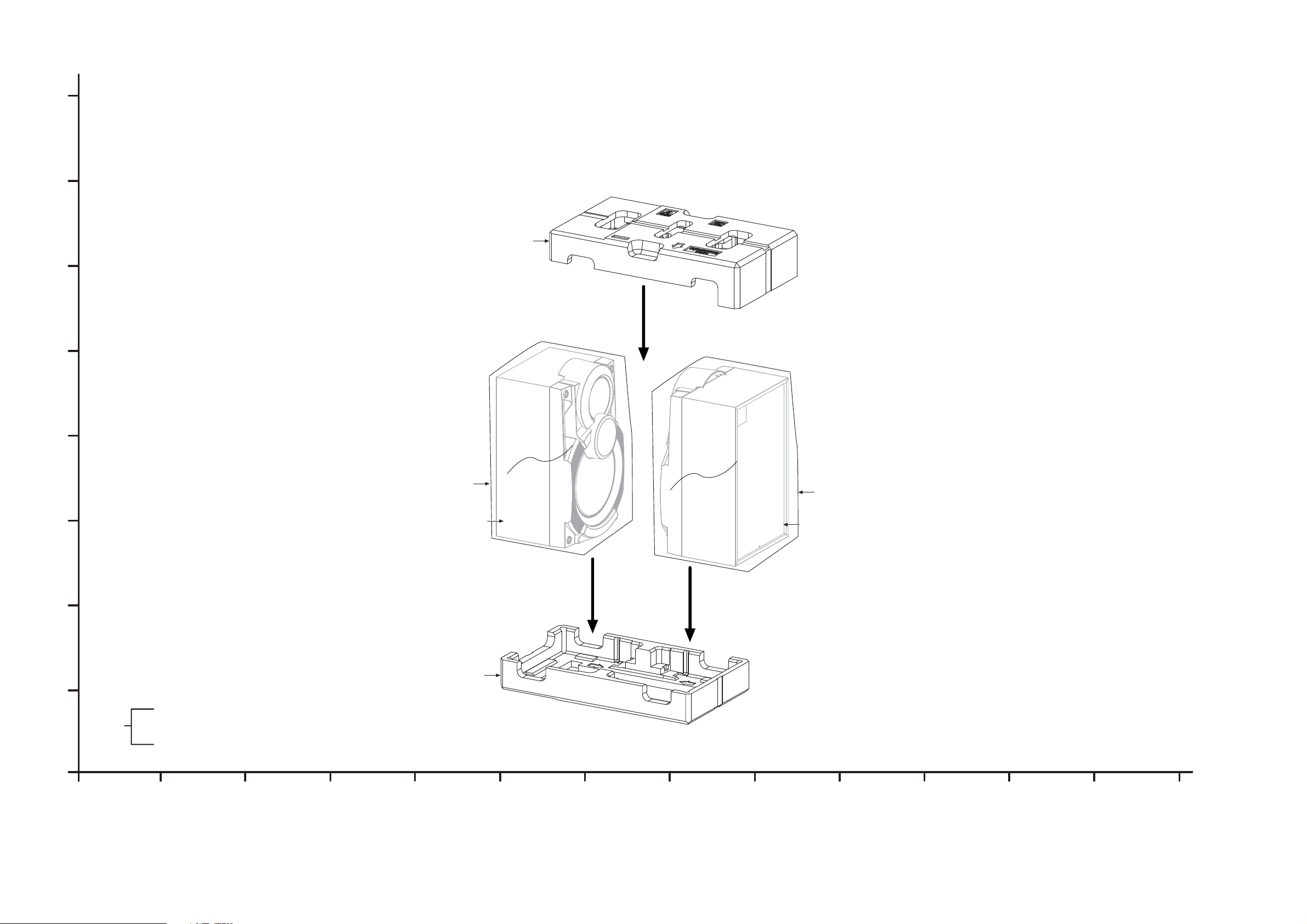
5.2. Packaging
12
Page 13
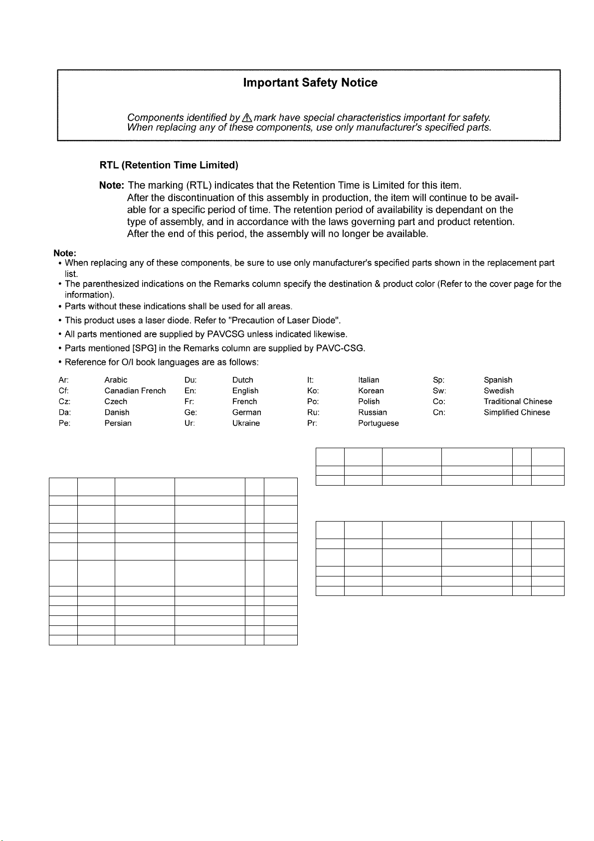
5.3. Replacement Parts List
5.3.1. Front Speakers (SB-AKX34PN-K)
Safety Ref. No. Part No. Part Name &
1 RYP1736-K FRONT PANEL ASSY 1
2 RFKHBAKX34PN SPEAKER BOX
2-1 RFKVBPT760-W SPEAKER CONNEC-
3 RMQX0285-K EVA PACKING 1
4 RKA0072-KJ LEG CUSHION 4
5 RGN3118-K SPEC LABEL 1
6 XTB4+16AFJK SCREW 8
7 XTB3+10JFJK SCREW 4
Description
CABINET AND
CHASSIS
ASS’Y
TOR HOUSING
(WHITE)
Qty Remarks
1
1
Safety Ref. No. Part No. Part Name &
SP1 EAS6PH124K TWEETER SPEAKER 1
SP2 L0AA20A00022 WOOFER SPEAKER 1
Description
Qty Remarks
5.3.2. Packing Materials (SB-AKX34PN-K)
Safety Ref. No. Part No. Part Name &
P1 RPN2351 POLYFOAM 1
P2 RPF0569 MIRAMAT BAG 2
Description
Packing Materials
Qty Remarks
IPSG1202
13
 Loading...