

Panasonic SBAK-450-PC, SBAK-450-P Service manual
Specifications
Type 2 way, 2 speaker system (Bass reflex)
Speaker(s)
Woofer 16 cm (6-1/2’’) cone type
Tweeter 6 cm (2-3/8’’) cone type
Impedance
HIGH 3 Ω
LOW 3 Ω
Input power (IEC)
HIGH 115 W (Max)
LOW 115 W (Max)
Output sound pressure level 84 dB/W (1.0 m)
Cross over frequency 2.6 kHz, 10 kHz
ORDER NO. MD0703006CE
A6
Speaker System
SB-AK450P
SB-AK450PC
Colour
(K)...Black Type
Frequency range 35 Hz to 25 kHz (-16 dB)
27 Hz to 28 kHz (-10 dB)
Dimensions (W X H X D) 219 X 330 X 216 mm
(8-5/8’’ X 13’’ X 8-1/2’’)
Mass 2.9kg(6.4Ib.)
Notes:
1. Specifications are subject to change without notice. Mass and
dimensions are approximate.
2. Total harmonic distortion is measured by the digital spectrum
analyzer.
3. The labels “HIGH”and “LOW” on the rear of the speakers refer to
High frequency and Low frequency.
CONTENTS
Page Page
1 System Combination
1.1. System Breakdown
2 Assembling and Disassembling
2.1. Caution
2.2. Disassembly Procedures
2.3. Disassembly Flow Chart
2.4. Disassembly of Rear cabinet assembly
2
2
3
3
3
3
4
2.5. Disassembly of Woofer
2.6. Disassembly of Tweeter
3 Connection of the Speaker Cables
4 Exploded Views
4.1. Cabinet Parts Location
4.2. Packaging
5 Replacement Parts List
© 2007 Matsushita Electric Industrial Co. Ltd.. All
rights reserved. Unauthorized copying and
distribution is a violation of law.
5
5
6
7
7
8
9

/ SB-AK450P / SB-AK45 0PC
1 System Combination
1.1. System Breakdown
Note:
The table below show the breakdown for speaker combinations used in main unit system.
System SC-AK450P-K
Music Center SA-AK450P-K
Front Speakers SB-AK450P-K
System SC-AK450PC-K
Music Center SA-AK450PC-K
Front Speakers SB-AK450PC-K
2
2 Assembling and Disassembling
2.1. Caution
“Attention Servicer”
Some chassis components may have sharp edges.
Be careful when disassembly and servicing.
1. This section describes procedure for checking the operation of replacing the main components.
2. For reassembly after operation checks or replacement, reverse the respective procedures.
3. Select items from the following index when checks or replacement are required.
4. Refer to the Part No.on the page of “Parts Location and Replacement Parts List” (Section 5) if necessary.
/ SB-AK450P / SB-AK45 0PC
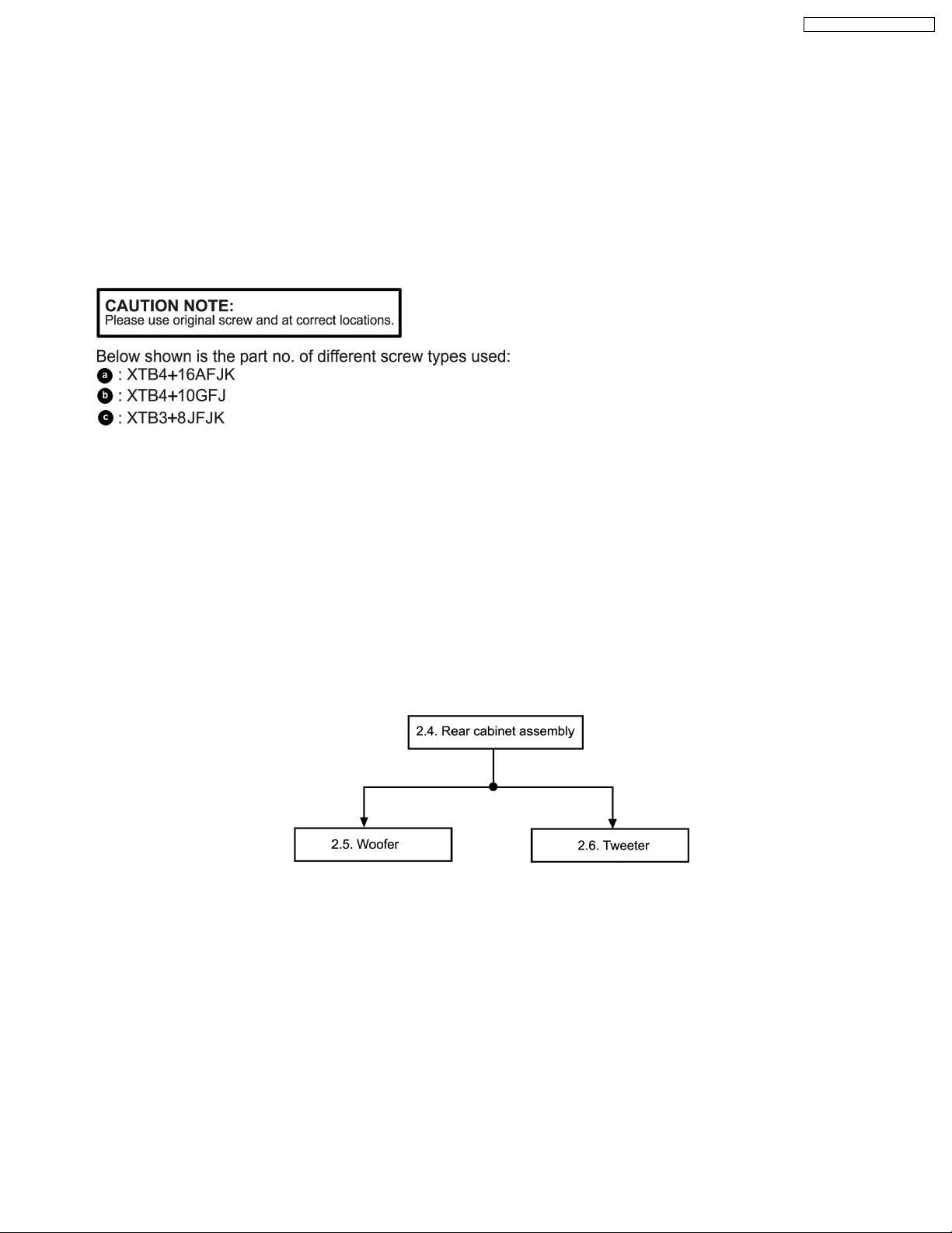
2.2. Disassembly Procedures
· Disassembly of Rear cabine t assembly
· Disassembly of Woofer
· Disassembly of Tweeter
2.3. Disassembly Flow Chart
The following chart is the procedure for disassembly the casing and inside parts for internal inspection when carrying out the
servicing.
To assemble the unit, reverse the steps shown in the chart as below.
3
 Loading...