

Panasonic SAVK-70 Service manual

Table Of Contents
COVER
1 Before Use
2 Before Repair and Adjustment
3 Protection Circuitry
4 Safety Precautions
4.1 General Guidelines
4.1.1 Leakage Current Cold Check
4.1.2 Leakage Current Hot Check (See Figure 1)
5 Prevention of Electro Static Discharge (ESD) to Electrostatically Sensitive (ES) Devices
6 Handling the Lead-free Solder
6.1 About lead free solder (PbF)
7 Cautions to be taken when handling Optical Pickup
7.1 Handling Optical Pickup
7.2 Replacing Precautions for Optical Pickup Unit
7.3 Grounding for Preventing Electrostatic Destruction
8 Precaution of Laser Diode
9 Accessories
10 Operation Procedures
11 Disc information

12 About HighMAT
12.1 What is HighMAT?
12.2 Why use HighMAT?
12.3 The advantages of using HighMAT
12.4 Outline of the HighMAT standard
13 Procedure for repairing the set
13.1 Distinguish the trouble cause
13.2 Diagnosis of Optical Pick-up Unit
14 Optical Pickup Self-Diagnosis and Replacement Procedure
14.1 Self-diagnosis
14.2 Cautions to Be Taken During Replacement of Optical Pickup and Spindle Motor
14.2.1 Cautions to be taken during replacement of optical pickup
15 Self-Diagnosis Function
15.1 Automatic Displayed Error Codes
15.1.1 Automatic Display Function
15.1.2 Re-Display
15.1.3 Description of Error Code
15.2 Memorized Error Codes
15.2.1 Activating Self-Diagnosis Function and Displaying Method
15.2.2 Re-Display
15.3 Mode Table 1

15.4 DVD / CD Self-Diagnosis Error Code Description
PV
15.5 Error Codes Stored During No Play
15.6 Mode Table 2
15.7 Tray Lock Function
15.7.1 Setting
15.8 Things to Do After Repair
16 Cautions To Be Taken During Servicing
16.1 Recovery after the dvd player is repaired
16.2 DVD Player Firmware Version Upgrade Process
16.3 Firmware Version Upgrade Process by Using Disc and Recovery Process
16.3.1 Self-Diagnosis Function
16.4 Using Recovery Disc
16.4.1 Recovery Process
16.4.2 Version Upgrade Process
16.5 Total Usage Time Display
17 Operation Checks and Component Replacement Procedures
17.1 Disassembly of Top Cabinet
17.2 Disassembly for the DVD changer ass ’ y
17.2.1 Disassembly for the Top Ornament Unit
17.2.2 Disassembly for DVD changer unit

17.3 Checking for the changer unit operational condition
17.3.1 Initial setting of CD
17.3.2 Checking for the DVD Module (1) P.C.B.
17.3.3 Checking for Panel P.C.B., Deck P.C.B. and LED P.C.B.
17.3.4 Replacement of the Power Amplifier IC
17.4 Main Component Replacement Procedures
17.4.1 Replacement of the Traverse Deck
17.5 Replacement for the disc tray
17.6 Disassembly and reassembly for mechanism base drive unit
17.7 Replacement for the motor ass ’ y
17.8 Replacement for the pinch roller ass ’ y and head block
17.9 Replacement for the CD motor ass ’ y, capstan belt A, capstan belt B and winding belt
17.10 Replacement for the CD motor ass ’ y, capstan belt A, capstan belt B and winding belt
17.11 Replacement for the cassette lid ass ’ y
17.12 Measure for tape trouble
18 Measurements and Adjustments
18.1 Cassette Deck Section
18.1.1 Head Azimuth Adjustment (Deck 1 / 2)
18.1.2 Tape Speed Adjustment (Deck 1 / 2)
18.1.3 Bias and Erase Voltage Check
18.1.4 Bias Frequency Adjustment (Deck 1 / 2)

18.2 Tuner Section
18.2.1 AM-IF Alignment
18.2.2 AM RF Adjustment
18.3 Alignment Points
18.3.1 Cassette Deck Section
18.3.2 Adjustment Point
19 Illustration of ICs, Transistors and Diodes
20 Terminal Function of IC
20.1 IC600 (C2BBHF000075 ) System Microprocessor
21 Block Diagram
22 Schematic Diagram
22.1 (A) DVD Module (1) Circuit
22.2 (B) DVD Module (2) Circuit
22.3 (C) Main Circuit & (D) Tuner Extent Circuit
22.4 (E) Panel Circuit, (F) LED Circuit & (G) Tact Switch Circuit
22.5 (H) Tuner Circuit
22.6 (J) Deck Circuit & (K) Deck Mechanism Circuit
22.7 (L) Power Supply Circuit
22.8 (M) Power Circuit
22.9 (N) Transformer Circuit, (O) AC Inlet Circuit, (P) Voltage Selector Circit, (Q) CD Loading
Circuit, (R) CD Detect Circuit & (S) Spindle Position Circuit

23 Printed Circuit Board
23.1 (A) DVD Module (1) P.C.B. (Component & Foil Side)
23.2 (B) DVD Module (2) P.C.B. (Side A & B)
23.3 (C) Main P.C.B.
23.4 (D) Tuner Extent P.C.B., (F) LED P.C.B., (I) Tuner Pack P.C.B., (Q) CD Loading P.C.B., (R)
CD Detect P.C.B. & (S) Spindle Position P.C.B.
23.5 (E) Panel P.C.B.
23.6 (G) Tact Switch & (H) Tuner P.C.B.
23.7 (J) Deck P.C.B. & (K) Deck Mechanism P.C.B.
23.8 (L) Power Supply P.C.B.
23.9 (M) Power P.C.B.
23.10 (N) Transformer P.C.B.
23.11 (O) AC Inlet P.C.B. & (P) Voltage Selector P.C.B.
24 Wiring Connection Diagram
25 Parts Location and Replacement Parts List
25.1 Deck Mechanism (RAA3412-S)
25.1.1 Deck Mechanism Parts Location
25.1.2 Deck Mechanism Parts List
25.2 CD Loading Mechanism (RD-DAC036-S)
25.2.1 CD Loading Mechanism Parts Location
25.2.2 CD Loading Mechanism Parts List

25.3 Cabinet
25.3.1 Cabinet Parts Location
25.3.2 Cabinet Parts List
25.4 Electrical Parts List
25.5 Packing Materials & Accessories Parts List
25.6 Packaging
Service Manual
TOP NEXT
ORDER NO. MD0309424C3
DVD Stereo System
● SA-VK70DGC
SA-VK70DGCS
Colour
(K)... Black Type (For SA-VK70DGC& SA-VK70DGCS only)
(S)... Silver Type (For SA-VK70DGCS only)
AMPLIFIER SECTION
RMS Output power both channel driven: 10% Total Harmonic Distortion
1 kHz Front CH
Specifications
100 W per channel (6Ω )

Total RMS Dolby Digital Mode Power
200 W
PMPO Output Power 2200 W
Input sensitivity/ Input Impedance
AUX
Mic
FM TUNER SECTION
Frequency range 87.5 - 108.0 MHz (50 kHz steps)
Sensitivity
S/ N 26 dB
Antenna terminals
Preset station 15
AM TUNER SECTION
Frequency range 522 - 1629 kHz (9 kHz steps)
520 - 1630 kHz (10 kHz steps)
AM sensitivityy S/ N 20 dB at 1000 kHz
Preset station 15
CASSETTE DECK SECTION
Track system 4 track, 2 channel
Heads
Record/ playback Solid permalloy head
Erasure Double gap ferrite head
Motor DC servo motor
Recording system AC bias 100 kHz
Erasing system AC erase 100 kHz
Tape speed 4.8 cm/ s (1 7/ 8 ips)
Overall frequency response (+ 3 dB, -6 dB at DECK OUT)
Normal (TYPE I) 35 Hz - 14 kHz
S/ N ratio 50 dB (A weighted)
Wow and flutter 0.18% (WRMS)
Fast forward and rewind time Approx. 120 seconds with
Disc SECTION
Disc played (one layer per side)
DVD-Video/ Audio
8 cm/ 12 cm, single/ double-sided, single/ double-layer
DVD-RAM/ R (DVD-Video formatted discs)
CD-DA/ VCD/ MP3/ WMA 8 cm/ 12 cm, CD-R/ RW
SVCD (Conforming to IEC62107)
250 mV, 13.3 kΩ
0.7 mV, 680Ω
2.5μ V (IHF)
2.2μ V
75Ω (unbalanced)
560μ V/ m
C-60 cassette tape

HighMAT Level 2 (Audio and Image)
JPEG-Exif Ver 2.1 JPEG Baseline files
Video
Signal system PAL625/ 50, PAL525/ 60,NTSC
Output level
Composite video
S-Video Y
S-Video C
0.286 Vp-p (75Ω )(NTSC)
Component video
0.7 Vp-p (PB/ CB PR/ CR)(75Ω )
Audio
Sampling frequency
CD 44.1 kHz
MP3 32 kHz, 44.1 kHz, 48 kHz
DVD-Video 48 kHz, 96 kHz
DVD-Audio 192 kHz
MP3
Birate 32- 320 kbps
Decoding 16/ 20/ 24 bit linear
Number of channels Stereo
Frequency response 20 Hz- 20 kHz (+ 1, -2 dB)
Pick up
Beam Source Semiconductor Laser
Wavelength
CD/ VCD 780 nm
DVD 658 nm
Wow and flutter Less than possible measurement data
Digital filter 8 fs
D/ A converter Delta sigma DAC
Digital audio output
Optical digital output Optical terminal
GENERAL
Power supply AC 110V/ 127V/ 220-230V/ 240 V, 50/ 60 Hz
Power consumption 146 W
Power consumption in standby mode:
Dimwnsions (W x H x D) 250 x 330 x 370 mm
Mass 8.0 kg
SYSTEM
1 Vp-p (75Ω )
1 Vp-p (75Ω )
0.3 Vp-p (75Ω )(PAL)
1 Vp-p (Y)(75Ω )
0.9 W
SC-VK70D(GC-K) Music Center: SA-VK70D(GC-K)
Front Speaker: SB-VK70(GC-K) x 2
Surround Speaker: SB-PS810(GC-K) x 2
SC-VK70D(GCS-K) Music Center: SA-VK70D(GCS-K)
Front Speaker: SB-VK70(GC-K) x 2
Surround Speaker: SB-PS810(GC-K) x 2
SC-VK70D(GCS-S) Music Center: SA-VK70D(GCS-S)
Front Speaker: SB-VK70(GC-S) x 2
Surround Speaker: SB-PS810(GC-S) x 2
Notes:
1. Specifications are subject to change without notice. Mass and dimensions are approximate.
2. Total harmonic distortion is measured by the digital spectrum analyzer.
© 2003 Panasonic AVC Networks Singapore Pte. Ltd. All rights reserved. Unauthorized copying and distribution is a violation of law.
TOP NEXT

1 Before Use
TOP PREVIOUS NEXT
Be sure to disconnect the mains cord before adjusting the voltage selector.
Use a minus(-) screwdriver to set the voltage selector (on the rear panel) to the voltage setting for the
area in which the unit will be used. (If the power supply in your area is 117V or 120V, set to the
“127V” position.)
Note that this unit will be seriously damaged if this setting is not made correctly. (There is no voltage
selector for some countries, the correct voltage is already set.)
TOP PREVIOUS NEXT

2 Before Repair and Adjustment
TOP PREVIOUS NEXT
Disconnect AC power, discharge Power Supply Capacitors C531~C534, C588~C589, C598~C599
and C954 through a 10Ω, 5W resistor to ground.
DO NOT SHORT-CIRCUIT DIRECTLY (with a screwdriver blade, for instance), as this may
destroy solid state devices.
After repairs are completed, restore power gradually using a variac, to avoid overcurrent.
Current consumption at AC 110/127/220~230V, 50/60 Hz in NO SIGNAL (vol. min, at CD mode) &
AC 240 V, 50 Hz should be ~770mA and ~370mA respectively.
TOP PREVIOUS NEXT

3 Protection Circuitry
TOP PREVIOUS NEXT
The protection circuitry may have operated if either of the following conditions are noticed:
● No sound is heard when the power is turned on.
● Sound stops during a performance.
The function of this circuitry is to prevent circuitry damage if, for example, the positive and negative
speaker connection wires are
“shorted”, or if speaker systems with an impedance less than the indicated rated impedance of the
amplifier are used.
If this occurs, follow the procedure outlines below:
1. Turn off the power.
2. Determine the cause of the problem and correct it.
3. Turn on the power once again after one minute.
Note :
When the protection circuitry functions, the unit will not operate unless the power is first turned off
and then on again.
TOP PREVIOUS NEXT

4 Safety Precautions
TOP PREVIOUS NEXT
4.1 General Guidelines
4.1.1 Leakage Current Cold Check
4.1.2 Leakage Current Hot Check (See Figure 1)
TOP PREVIOUS NEXT

4.1 General Guidelines
TOP PREVIOUS NEXT
1. When servicing, observe the original lead dress. If a short circuit is found, replace all parts
which have been overheated or damaged by the short circuit.
2. After servicing, see to it that all the protective devices such as insulation barriers, insulation
papers shields are properly installed.
3. After servicing, make the following leakage current checks to prevent the customer from
being exposed to shock hazards.
4.1.1 Leakage Current Cold Check
4.1.2 Leakage Current Hot Check (See Figure 1)
TOP PREVIOUS NEXT
4.1.1 Leakage Current Cold Check
TOP PREVIOUS NEXT
1. Unplug the AC cord and connect a jumper between the two prongs on the plug.
2. Measure the resistance value, with an ohmmeter, between the jumpered AC plug and each
exposed metallic cabinet part on the equipment such as screwheads, connectors, control shafts,
etc. When the exposed metallic part has a return path to the chassis,the reading should be
between 1MΩ and 5.2MΩ.
When the exposed metal does not have a return path to the chassis, the reading must be ¥.
Figure 1
TOP PREVIOUS NEXT

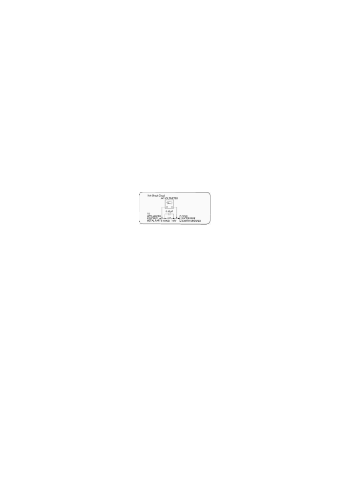
4.1.2 Leakage Current Hot Check
(See Figure 1)
TOP PREVIOUS NEXT
1. Plug the AC cord directly into the AC outlet. Do not use an isolation transformer for this
check.
2. Connect a 1.5kΩ, 10 watts resistor, in parallel with a 0.15μF capacitor, between each
exposed metallic part on the set and a good earth ground such as a water pipe, as shown in
Figure 1.
3. Use an AC voltmeter, with 1000 ohms/volt or more sensitivity, to measure the potential across
the resistor.
4. Check each exposed metallic part, and measure the voltage at each point.
5. Reverse the AC plug in the AC outlet and repeat each of the above measurements.
6. The potential at any point should not exceed 0.75 volts RMS. A leakage current tester
(Simpson Model 229 or equivalent) may be used to make the hot checks, leakage current must
not exceed 1/2 milliamp. In case a measurement is out ofthe limits specified, there is a
possibility of a shock hazard, and the equipment should be repaired and rechecked before it is
returned to the customer.
TOP PREVIOUS NEXT

5 Prevention of Electro Static Discharge (ESD)
to Electrostatically Sensitive (ES) Devices
TOP PREVIOUS NEXT
Some semiconductor (solid state) devices can be damaged easily by electricity. Such components
commonly are called Electrostatically Sensitive (ES) Devices. Examples of typical ES devices are
integrated circuits and some field-effect transistorsand semiconductor “chip” components. The
following techniques should be used to help reduce the incidence of component damage caused by
electro static discharge (ESD).
1. Immediately before handling any semiconductor component or semiconductor-equiped
assembly, drain off any ESD on your body by touching a known earth ground. Alternatively,
obtain and wear a commercially available discharging ESD wrist strap, whichshould be
removed for potential shock reasons prior to applying power to the unit under test.
2. After removing an electrical assembly equiped with ES devices, place the assembly on a
conductive surface such as aluminium foil, to prevent electrostatic charge build up or exposure
of the assembly.
3. Use only a grounded-tip soldering iron to solder or unsolder ES devices.
4. Use only an anti-static solder remover device. Some solder removal devices not classified as
“anti-static (ESD protected)” can generate electrical charge to damage ES devices.
5. Do not use freon-propelled chemicals. These can generate electrical charges sufficient to
damage ES devices.
6. Do not remove a replacement ES device from its protective package until immediately before
you are ready to install it. (Most replacement ES devices are packaged with leads electrically
shorted together by conductive foam, aluminium foil orcomparable conductive material).
7. Immediately before removing the protective material from the leads of a replacement ES
device, touch the protective material to the chassis or circuit assembly into which the device
will be installed.
Caution
Be sure no power is applied to the chassis or circuit, and observe all other safety precautions.
8. Minimize body motions when handling unpackaged replacement ES devices. (Otherwise
harmless motion such as the brushing together of your clothes fabric or the lifting of your foot

from a carpeted floor can generate static electricity (ESD) sufficient todamage an ES device).
TOP PREVIOUS NEXT

6 Handling the Lead-free Solder
TOP PREVIOUS NEXT
6.1 About lead free solder (PbF)
TOP PREVIOUS NEXT

6.1 About lead free solder (PbF)
TOP PREVIOUS NEXT
Distinction of PbF P.C.B.:
P.C.B.s (manufactured) using lead free solder will have a PbF stamp on the P.C.B.
Caution:
● Pb free solder has a higher melting point than standard solder; Typically the melting point is
50 - 70°F (30 - 40°C) higher. Please use a high temperature soldering iron. In case of
soldering iron with temperature control,please set it to 700 ± 20°F (370 ± 10°C).
● Pb free solder will tend to splash when heated too high (about 1100°F/600°C).
● When soldering or unsoldering, please completely remove all of the solder on the pins or
solder area, and be sure to heat the soldering points with the Pb free solder until it melts
enough.
TOP PREVIOUS NEXT

7 Cautions to be taken when handling Optical
Pickup
TOP PREVIOUS NEXT
The laser diode used inside optical pickup could be destroyed due to static electricity as a potential
difference is caused by electrostatic load discharged from clothes or human body. Handling the parts
carefully to avoid electrostatic destructionduring repair.
7.1 Handling Optical Pickup
7.2 Replacing Precautions for Optical Pickup Unit
7.3 Grounding for Preventing Electrostatic Destruction
TOP PREVIOUS NEXT
7.1 Handling Optical Pickup
TOP PREVIOUS NEXT
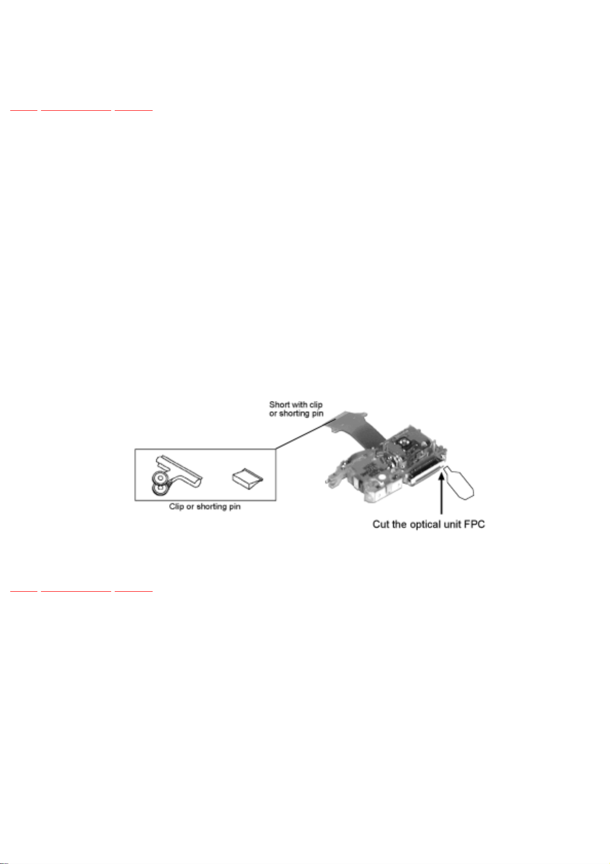
1. Do not impact on optical pickup as the unit structurally uses an extremely precise technology.
2. Short-circuit the flexible cable of optical pickup remove from the circuit board using a shortcircuit pin or clip in order to prevent laser diode from electrostatic destruction (Refer to Fig.
7.1 and Fig. 7.2)
3. Do not handle flexible cables forcibly as this may cause snapping. Handle the parts carefully
(Refer to Fig. 7.1)
4. A new optical pickup is equipped with an anti-static flexible cable. After replacing and
connecting to the flexible board, cut the anti-static flexible cable. (Refer to Fig. 7.1)
Fig. 7.1
TOP PREVIOUS NEXT

7.2 Replacing Precautions for Optical Pickup
Unit
TOP PREVIOUS NEXT
DVD/CD Optical Pickup
The optical pickup by which part supply was carried out attaches the short clip to the flexible board
for laser diode electrostatic discharge damage prevention. Please remove the short clip and be sure to
check that the short land is open, beforeconnecting. (Please remove solder, when the short land shortcircuits.)
TOP PREVIOUS NEXT
7.3 Grounding for Preventing Electrostatic
Destruction
TOP PREVIOUS NEXT
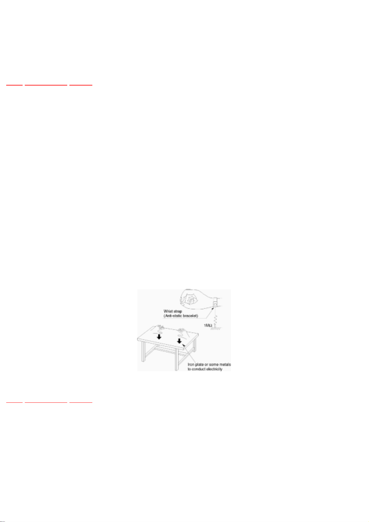
1. Human body grounding
Use the anti-static wrist strap to discharge the static electricity accumulated in your body.
(Refer to Fig. 7.2)
2. Work place grounding
Place a conductive material (conductive sheet) or ironboard where optical pickup is placed.
(Refer to Fig. 7.2)
Note :
Keep your clothes away from optical pickup as wrist strap does not release the static electricity
charged in clothes.
Fig. 7.2
TOP PREVIOUS NEXT

8 Precaution of Laser Diode
TOP PREVIOUS NEXT
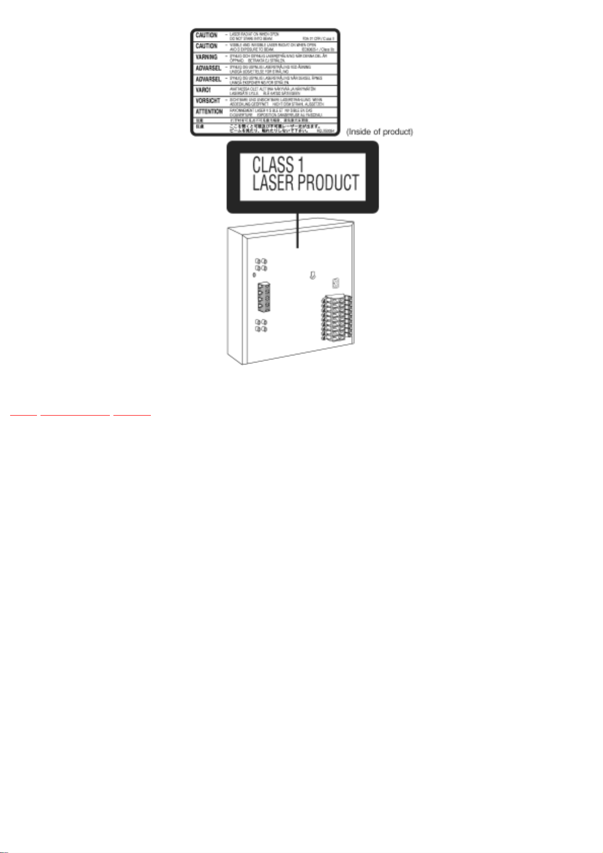
CAUTION :
This unit utilizes a class 1 laser.
Invisible laser radiation is emitted from the optical pickup lens.
Wavelength: 658nm(DVD)/780nm(VCD/CD).
Maximum output radiation power from pickup: 100μW/VDE
When the unit is turned on :
1. Do not look directly into the pick up lens.
2. Do not use optical instruments to look at the pick up lens.
3. Do not adjust the preset variable resistor on the pickup lens.
4. Do not disassemble the optical pick up unit.
5. If the optical pick up is replaced, use the manufacturer’s specified replacement pick up only.
6. Use of control or adjustments or performance of procedures other than those specified herein
may result in hazardous radiation exposure.
CAUTION!
THIS PRODUCT UTILIZES A LASER.
USE OF CONTROLS OR ADJUSTMENTS OR PERFORMANCE OF PROCEDURES OTHER THAN THOSE SPECIFIED
HEREIN MAY RESULT IN HAZARDOUS RADIATION EXPOSURE.
Use of Caution Labels
TOP PREVIOUS NEXT
9 Accessories
TOP PREVIOUS NEXT
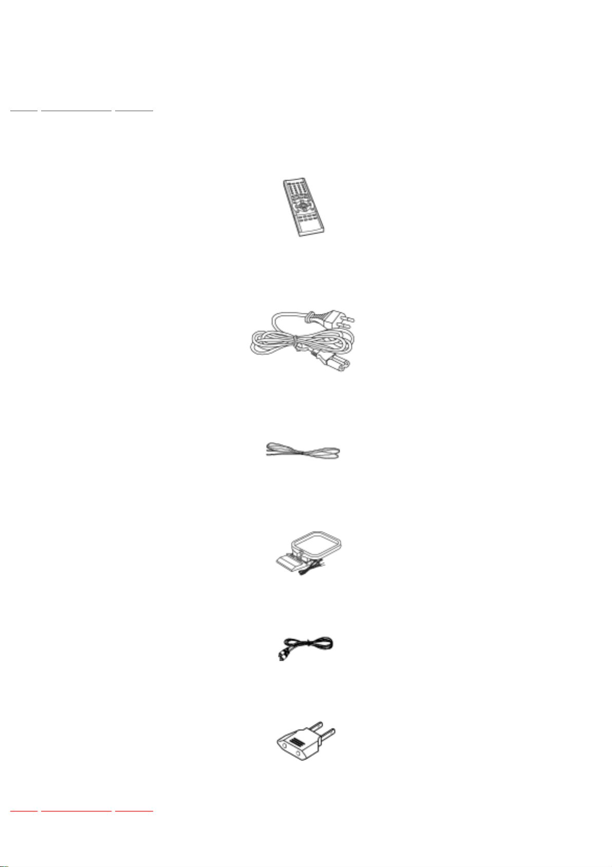
Remote Control
AC power supply cord
FM indoor antenna
AM indoor antenna
Video cable
Power plug adaptor
TOP PREVIOUS NEXT

10 Operation Procedures
TOP PREVIOUS NEXT
TOP PREVIOUS NEXT
 Loading...