

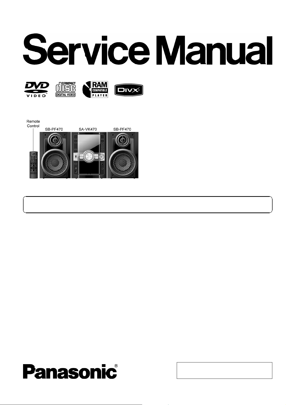
Panasonic SAVK-470-EE Service manual
A
r
DVD Stereo System
SA-VK470EE
Colour
(K).......................Black Type
ORDER NO. MD0805014CE
Notes: This model’s DVD/CD mechanism changer unit is CR14. Please refer to the original service manual
(Order No. MD0801004CE) for this m echanism.
Specifications
Q
Q AMPLIFIER SECTION
QQ
RMS Output Power Stereo mode:
Front Ch
125 W per channel (3 Ω), 1 kHz, 10% THD
Total RMS Stereo mode power 250 W
PMPO output power 2800 W
Q
Q FM/AM TUNER, TERMINALS SECTION
QQ
Preset station FM 30 stations
AM 15 stations
Frequency Modulation (FM)
Frequency range 87.50 to 108.00 MHz (50 kHz
step)
Antenna terminals 75 Ω (unbalanced)
Amplitude Modulation (AM)
Frequency range 522 to 1629 kHz (9 kHz step)
Digital audio output
Coaxial digital output Pin jack
Music Port (Front)
Terminal Stereo, 3.5 mm jack
Phone jack
Terminal Stereo, 3.5 mm jack
Mic jack
Terminal Mono, 6.3 mm jack (1 system)
UX
Terminal Stereo, RCA jack
Q
Q CASSETTE DECK SECTION
QQ
Type Auto reverse
Track system 2-Track, 1 Channel
Heads
Record/playback Solid permalloy head
Erasure Double gap ferrite head
Motor DC servo moto
Recording system AC bias 100 kHz
Erasing system AC erase 100 kHz
Tape speed 4.8 cm/s
Overall frequency response (+3, -6 dB) at DECK OUT
Normal 35 Hz to 14 kHz
© 2008 Matsushita Electric Industrial Co. Ltd.. All
rights reserved. Unauthorized copying and
distribution is a violation of law.

A
SA-VK470EE
S/N ratio 50 dB (A-Weighted)
Wow and flutter 0.18% (WRMS)
Fast forward and rewind time Approx. 120 seconds with
C-60 cassette tape
Q
Q VIDEO SECTION
QQ
Video system PAL625/50, PAL525/60, NTSC
Composite video output
Output level 1 Vp-p (75 Ω)
Terminal Pinjack(1system)
Component video output
Y output level 0.7Vp-p(75Ω)
PBoutput level 0.7Vp-p(75Ω)
PRoutput level 0.7Vp-p(75Ω)
Terminal output level
Pin jack (Y: green, PB:blue,PR:red)(1system)
Q
QUSB SECTION
QQ
USB Port
USB standard USB 2.0 full speed
Media file format support MP3 (*.mp3)
WMA (*.wma)
JPEG (*.jpg) (*.jpeg)
MPEG4 (*.asf)
USB device file system FAT12, FAT16, FAT 32
USB Port power Max. 500 mA
Q
Q DISC SECTION
QQ
Disc played [8 cm or 12 cm]
(1) DVD (DVD-Video, DivX
(2) DVD-RAM (DVD-VR, JPEG
(3) DVD-R (DVD-Video, DVD-VR, JPEG
*6,*7
DivX
)
*6,*7
)
*4,*7
,MP3
*2,*7
*4,*7
, MPEG4
*2,*7
,MP3
*5,*7
, DivX
, MPEG4
*6,*7
*5,*7
)
,
(4) DVD-R DL (DVD-Video, DVD-VR)
(5) DVD-RW (DVD-Video, DVD-VR, JPEG
*6,*7
DivX
)
*4,*7
,MP3
*2,*7
, MPEG4
*5,*7
(6) +R/ +RW (Video)
(7) +R DL (Video)
(8) CD,CD-R/RW [CD-DA, Video CD, SVCD*1,MP3
JPEG
*4,*7
, MPEG4
*5,*7
, DivX
*6,*7
, HighMAT Level 2 (Audio and
*2,*7
,WMA
*3,*7
,
Image)]
*1
Conforming to IEC62107
*2
MPEG-1 Layer 3, MPEG-2 Layer 3
*3
Windows Media Audio Ver 9.0 L3
Not compatible with Multiple Bit Rate (MBR)
*4
Exif Ver 2.1 JPEG Baseline files
Picture resolution: between 160 x 120 and 6144 x 4096 pixels (Sub
sampling is 4:0:0, 4:2:0, 4:2:2 or 4:4:4). Extremely long and narrow
pictures may not be displayed.
*5
MPEG4 data recorded with the Panasonic SD multi cameras or
DVD video recorders. Conforming to SD VIDEO specifications (ASF
standard)/ MPEG4 (Simple Profile) video system/ G.726 audio
system.
*6
Plays all versions of DivX®video (including DivX®6) with standard
playback of DivX
®
media files. Certified to the DixV®Home Theater
Profile. GMC (Global Motion Compensation) is not supported.
*7
The total combined maximum number of recognizable audio,
picture and video contents and groups: 4000 audio, picture and video
contents and 400 groups.
Pick up
Wavelength
CD 785 nm
DVD 655 nm
Laser Power
CD CLASS 1M
DVD CLASS 1
udio output (Disc)
Number of channels 2 channel (FL, FR)
Q
Q GENERAL
QQ
Power supply
AC 230 V 50 Hz
Power consumption 65 W
Power consumption in standby mode:
0.4 W (approx.)
Dimensions (W x H x D) 250 mm x 331 mm x 317 mm
Mass 4.7 kg
Operating temperature range +0 to +40°C
Operating humidity range 35 to 80% RH (no condensation)
Q
Q SYSTEM
QQ
SC-VK470(EE) Music Center: SA-VK470 (EE)
Speaker: SB-PF470 (GC)
For information on speaker system, please refer to the original
Service Manual (Order No. MD0805016CE) for SB-PF470GC-K.
Notes:
1. Specifications are subject to changes without notice. Mass and
dimensions are approximate.
2. Total harmonic distortion is measured by the digital spectrum
analyzer.
,
2
SA-VK470EE
3

SA-VK470EE
CONTENTS
Page Page
1 Safety Precautions 6
1.1. GENERAL GUIDELINES
1.2. Before Repair and Adjustment
1.3. Protection Circuitry
1.4. Safety Parts Information
2 Prevention of Electrostatic Discharge (ESD) to
Electrostatically Sensitive (ES) Devices
3 Precaution of Laser Diode
4 About Lead Free Solder (PbF)
4.1. Service caution based on legal restrictions
5 Handling Precautions for Traverse Unit
5.1. Cautions to Be Taken in Handling the Optical Pickup Unit
5.2. Grounding for electrostatic breakdown prevention
6 Accessories
7 Operation Procedures
7.1. Main Unit key Button Operations
7.2. Remote Control Key Buttons Operations
7.3. Disc Information
7.4. Using the Music Port
7.5. Divx VOD Content
7.6. Connecting and Playing a USB Mass Storage Class
Device
8 Self-Diagnosis and Special Mode Setting
8.1. Service Mode Summary Table
8.2. Service Mode Table (For DVD)
8.3. Service Mode Table (For CR14)
8.4. DVD Self Diagnostic Function-Error Code
8.5. Sales Demonstration Lock Function
8.6. Service Precautions
9 Assembling and Disassembling
9.1. Caution
9.2. Disassembly flow chart
9.3. Main Components and P.C.B. Location
9.4. Disassembly of Top Cabinet
9.5. Disassembly of Mechanism Unit (CR14)
9.6. Disassembly of Rear Panel
9.7. Disassembly of Front Panel Unit
9.8. Disassembly of Panel P.C.B., Tact Switch P.C.B. &
Remote Sensor P.C.B., Side Bar (L) LED P.C.B. and Side
Bar (R) LED P.C.B.
9.9. Disassembly of Mic P.C.B.
9.10. Disassembly of USB P.C.B.
9.11. Disassembly of Music Port P.C.B.
9.12. Disassembly of CD Lid
9.13. Disassembly of Deck Mechanism Unit
9.14. Disassembly of Deck P.C.B.
9.15. Disassembly of Deck Mechanism
9.16. Disassembly of Deck Mechanism P.C.B.
9.17. Disassembly of Cassette Lid
9.18. Rectification for Tape Jam Problem
10
10
11
11
11
13
14
14
15
16
18
19
20
21
21
22
30
32
37
37
39
39
41
42
43
44
46
46
47
50
50
51
51
52
52
53
55
56
56
6
6
6
7
8
9
9.19. Disassembly of D-Amp P.C.B.
9.20. Replacement of Audio Digital Power Amp IC (IC5000)
9.21. Disassembly of Main P.C.B.
9.22. Disassembly of SMPS P.C.B.
9.23. Replacement of Switch Regulator IC (IC5701)
9.24. Replacement of Switch Regulator Diode (D5702)
9.25. Replacement of Regulator Diode (D5801)
9.26. Replacement of Regulator Diode (D5802)
9.27. Replacement of Regulator Diode (D5803)
9.28. Disassembly of AC Inlet P.C.B.
9.29. Disassembly of DVD Module P.C.B.
10 Disassembling and assemblin g Trave rse Unit Assembly in
play position
10.1. Disassembly of Traverse Unit (TRV) Assembly
10.2. Assembly of Traverse Unit Assembly
11 Service Fixture and Tools
12 Service Positi ons
12.1. Checking and Repairing of Main P.C.B.
12.2. Checking and Repairing Panel P.C.B., Deck P.C.B., Tact
Switch P.C.B., Music Port P.C.B. and Mic P.C.B.
12.3. Checking and Repairing of D-Amp P.C.B.
12.4. Checking and Repairing of AC Inlet P.C.B. & SMPS
P.C.B.
13 Procedure for Checking Operation of Individual Parts of Deck
Mechanism Unit
13.1. Operation Check with Cassette Tape
13.2. Operation Check without Cassette Tape
14 Measurement And Adjustments
14.1. Cassette Deck Section
15 Vol tage and Waveform Chart
15.1. DVD Module P.C.B.
15.2. D-Amp P.C.B.
15.3. Main P.C.B.
15.4. Panel, Mic, Tact Switch P.C.B.
15.5. Deck, Deck Mechanism P.C.B.
15.6. SMPS P.C.B.
15.7. Waveform Chart
16 Illustration of IC’s, Transistors and Diodes
17 Wiring Connection Diagra m
18 Block Diagra m
18.1. System Control
18.2. DVD (Servo)
18.3. DVD (Audio)
18.4. Video
18.5. Deck
18.6. Audio
18.7. Digital Audio Amp
18.8. Power
19 Schem atic Diagra m Notes
20 Schematic Diagram
20.1. DVD Module Circuit
56
58
58
60
61
62
63
64
65
65
66
68
68
69
70
70
70
70
72
74
76
76
76
77
77
79
79
80
81
82
83
83
84
86
87
89
89
90
91
92
93
94
95
96
97
99
99
4

SA-VK470EE
20.2. Main Circuit 103
20.3. Panel, Side Bar (L) Led, Side Bar (R) Led Circuit
20.4. Tact Switch, Music Port, Remote Sensor, Mic, USB Circuit
20.5. Deck Circuit
20.6. D-Amp Circuit
20.7. SMPS Circuit
20.8. Deck Mechanism & AC Inlet Circuit
21 Prin ted Ci rcui t Board
21.1. DVD Module P.C.B.
21.2. Main P.C.B.
21.3. Panel, Side Bar (L) LED & Side Bar (R) LED P.C.B.
21.4. Tact Switch, Music Port, Remote Sensor, Mic, USB P.C.B.
21.5. Deck, Deck Mechanism & AC Inlet P.C.B.
21.6. D-Amp P.C.B.
109
110
111
112
113
115
117
117
118
119
120
121
122
21.7. SMPS P.C.B.
22 Basic Troubleshooting Guide
22.1. Troubleshooting Guide for F61 and/or F76
22.2. Basic Troubleshooting Guide for Traverse Unit (DVD
Module P.C.B.)
22.3. Basic Troubleshooting Guide for HDMI AV Output
23 Terminal Function of IC’s
23.1. IC2801 (RFKWVK470GC): IC System Control
23.2. IC6901(C0HBB0000057): IC FL Driver
24 Expl od ed View s
24.1. Cabinet Parts Location
24.2. Deck Mechanism Parts Location (RAA4111-S)
24.3. Packaging
25 Repl acement Parts List
25.1. Component Parts List
26 Schem atic Diagra m for printing w ith letter size
123
125
125
131
132
134
134
134
137
137
139
140
141
142
155
5
SA-VK470EE
1 Safety Precautions
1.1. GENERAL GUIDELINES
1. When servicing, observe the original lead dress. If a short circuit is found, replace all parts which have been overheated or
damaged by the short circuit.
2. After servicing, see to it that all the protective devices such as insulation barriers, insulation papers shields are properly
installed.
3. After servicing, carry out the following leakage current checks to prevent the customer from being exposed to shock hazards.
1.1.1. LEAKAGE CURRENT COLD CHECK
1. Unplug the AC cord and connect a jumper between the two prongs on the plug.
2. Measure the resistance value, with an ohmmeter, between the jumpered AC plug and each exposed metallic cabinet part on
the equipment such as screwheads, connectors, control shafts, etc. When the exposed metallic part has a return path to the
chassis, the reading should be between 1MΩ and 5.2MΩ.
When the exposed metal does not have a return path to the chassis, the reading must be
1.1.2. LEAKAGE CURRENT HOT CHECK
1. Plug the AC cord directly into the AC outlet. Do not use an isolation transformer for this check.
2. Connect a 1.5kΩ, 10 watts resistor, in parallel with a 0.15µF capacitors, between each exposed metallic part on the set and a
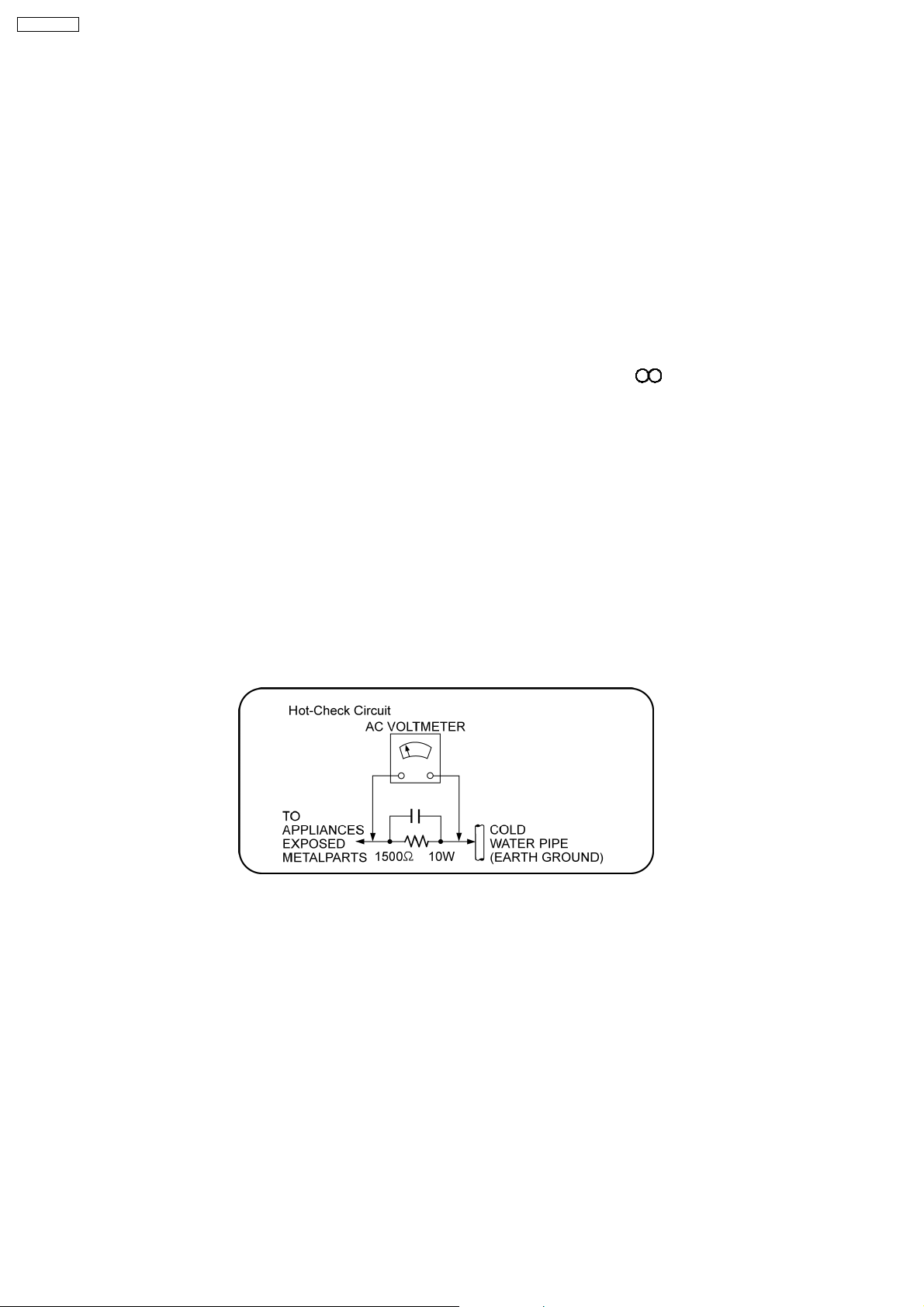
good earth ground such as a water pipe, as shown in Figure 1.
3. Use an AC voltmeter, with 1000 ohms/volt or more sensitivity, to measure the potential across the resistor.
4. Check each exposed metallic part, and measure the voltage at each point.
5. Reverse the AC plug in the AC outlet and repeat each of the above measurements.
6. The potential at any point should not exceed 0.75 volts RMS. A leakage current tester (Simpson Model 229 or equivalent) may
be used to make the hot checks, leakage current must not exceed 1/2 milliamp. In case a measurement is outside of the limits
specified, there is a possibility of a shock hazard, and the equipment should be repaired and rechecked before it is returned to
the customer.
Figure 1
1.2. Before Repair and Adjustment
Disconnect AC power to discharge unit AC Capacitors as such (C5700, C5701, C5703, C5704, C5705, C5706, C5707) through a
10 Ω, 10 W resistor to ground.
Caution:
DO NOT SHORT-CIRCUIT DIRECTLY (with a screwdriver blade, for instance), as this may destroy solid state devices.
After repairs are completed, restore power gradually using a variac, to avoid overcurrent.
Current consumption at AC 230 V, 50 Hz in NO SIGNAL mode volume minimal should be ~ 500 mA.
1.3. Protection Circuitry
The protection circuitry may have operated if either of the following conditions are noticed:
•
• No sound is heard when the power is turned on.
• •
•
• Sound stops during a performance.
• •
The function of this circuitry is to prevent circuitry damage if, for example, the positive and negative speaker connection wires are
6
“shorted”, or if speaker systems with an impedance less than the indicated r ated impedance of the amplifier are used.
If this occurs, follow the procedure outlines below:
1. Turn off the power.
2. Determine the cause of the problem and correct it.
3. Turn on the power once again after one minute.
Note:
When the protection circuitry functions, the unit will not operate unless the power is first turned off and then on again.
1.4. Safety Parts Information
Safety Parts List:
There are special components used in this equipment which are important for safety.
These parts are marked by
should be replaced with manufacturer’s specified parts to prevent shock, fire or other hazards. Do not modify the original design
without permission of manufacturer.
Ref. No. Part No. Part Name & Description Remarks
18 RGRX0070L-B REAR PANEL [M]
36 RKMX0144-K TOP CABINET [M]
68 REXX0684 BLACK WIRE [M]
69 REXX0685 RED WIRE [M]
A2 K2CQ2CA00007 AC CORD [M]
PCB4 REPX0622Y SMPS P.C.B [M] (RTL)
PCB5 REPX0622Y AC INLET P.C.B [M] (RTL)
DZ5701 ERZV10V511CS ZNR [M]
L5701 ELF15N035AN LINE FILTER [M]
L5702 ELF22V035B LINE FILTER [M]
L5703 ELF22V020A LINE FILTER [M]
T2900 G4D1A0000117 SWITCHING TRANSFORMER [M]
T5701 ETS42BN1A6AD MAIN POWER TRANSFORMER [M]
T5751 ETS19AB256AG BACKUP SW TRANSFORMER [M]
PC5701 B3PBA0000402 PHOTO COUPLER [M]
PC5702 B3PBA0000402 PHOTO COUPLER [M]
PC5720 B3PBA0000402 PHOTO COUPLER [M]
PC5799 B3PBA0000402 PHOTO COUPLER [M]
F1 K5D502BNA005 FUSE [M]
FP2901 K5G401A00008 FUSE PROTECTOR [M]
TH5701 D4CAC8R00002 THERMISTOR [M]
TH5860 D4CC11040013 THERMISTOR [M]
P5701 K2AA2B000017 AC INLET [M]
C5701 F0CAF334A087 0.33uF [M]
C5704 F1BAF1020020 1000pF [M]
C5705 F1BAF1020020 1000pF [M]
C5706 F1BAF1020020 1000pF [M]
C5707 F1BAF1020020 1000pF [M]
in the Schematic Diagrams & Replacement Parts List. It is essential that these critical parts
Table 1
SA-VK470EE
7

SA-VK470EE
2 Prevention of Electrostatic Discharge (ESD) to
Electrostatically Sensitive (ES) Devices
Some semiconductor (solid state) devices can be damaged easily by static electricity. Such components commonly are called
Electrostatically Sensitive (ES) Devices. Examples of typical ES devices are integrated circuits and some field-effect transistors and
semiconductor “chip” components. The following techniques should be used to help reduce the incidence of component damage
caused by electrostatic discharge (ESD).
1. Immediately before handling any semiconductor component or semiconductor-equipped assembly, drain off any ESD on your
body by touching a known earth ground. Alternatively, obtain and wear a commercially available discharging ESD wrist strap,
which should be removed for potential shock reasons prior to applying power to the unit under test.
2. After removing an electrical assembly equipped with ES devices, place the assembly on a conductive surface such as
aluminum foil, to prevent electrostatic charge buildup or exposure of the assembly.
3. Use only a grounded-tip soldering iron to solder or unsolder ES devices.
4. Use only an anti-static solder removal device. Some solder removal devices not classified as “anti-static (ESD protected)” can
generate electrical charge sufficient to damage ES devices.
5. Do not use freon-propelled chemicals. These can generate electrical charges sufficient to damage ES devices.
6. Do not remove a replacement ES device from its protective package until immediately before you are ready to install it. (Most
replacement ES devices are packaged with leads electrically shorted together by conductive foam, aluminum foil or comparable
conductive material).
7. Immediately before removing the protective material from the leads of a replacement ES device, touch the protective material
to the chassis or circuit assembly into which the device will be installed.
Caution:
Be sure no power is applied to the chassis or circuit, and observe all other safety precautions.
8. Minimize bodily motions when handling unpackaged replacement ES devices. (Otherwise harmless motion such as the
brushing together of your clothes fabric or the lifting of your foot from a carpeted floor can generate static electricity (ESD)
sufficient to damage an ES device).
8
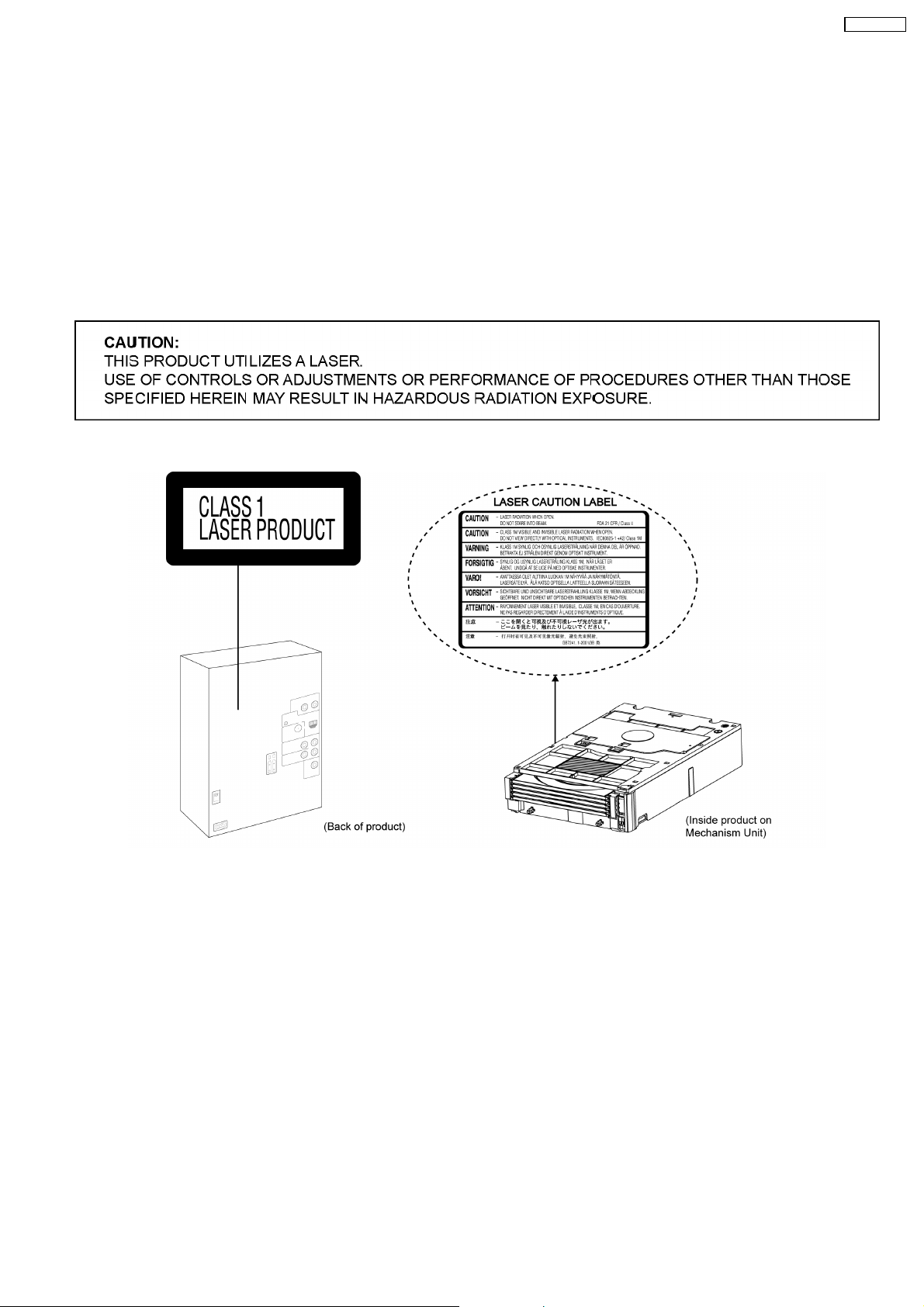
3 Precaution of Laser Diode
CAUTION:
This product utilizes a laser diode with the unit turned “on”, invisible laser radiation is emitted from the pickup lens.
Wavelength: 655 nm (DVD)/785 nm (CD)
Maximum output radiation power from pickup: 100 µW/VDE
Laser radiation from the pickup unit is safety level, but be sure the followings:
1. Do not disassemble the pickup unit, since radiation from exposed laser diode is dangerous.
2. Do not adjust the variable resistor on the pickup unit. It was already adjusted.
3. Do not look at the focus lens using optical instruments.
4. Recommend not to look at pickup lens for a long time.
SA-VK470EE
9
SA-VK470EE
4 About Lead Free Solder (PbF)
4.1. Service caution based on legal restrictions
4.1.1. General description about Lead Free Solder (PbF)
The lead free solder has been used in the mounting process of all electrical components on the printed circuit boards used for this
equipment in considering the globally environmental conservation.
The normal solder is the alloy of tin (Sn) and lead (Pb). On the other hand, the lead free solder is the alloy mainly consists of tin
(Sn), silver (Ag) and Copper (Cu), and the melting point of the lead free solder is higher approx.30 degrees C (86°F) more than that
of the normal solder.
Definition of PCB Lead Free Solder being used
The letter of “PbF” is printed either foil side or components side on the PCB using the lead free solder.
(See right figure)
Service caution for repair work using Lead Free Solder (PbF)
•
• The lead free solder has to be used when repairing the equipment for which the lead free solder is used.
• •
(Definition: The letter of “PbF” is printed on the PCB using the lead free solder.)
•
• To put lead free solder, it should be well molten and mixed with the original lead free solder.
• •
•
• Remove the remaining lead free solder on the PCB cleanly for soldering of the new IC.
• •
•
• Since the melting point of the lead free solder is higher than that of the normal lead solder, it takes the longer time to melt
• •
the lead free solder.
•
• Use the soldering iron (more than 70W) equipped with the temperature control after setting the temperature at 350±30
• •
degrees C (662±86°F).
Recommended Lead Free Solder (Service Parts Route.)
•
• The following 3 types of lead free solder are available through the service parts route.
• •
RFKZ03D01K-----------(0.3mm 100g Reel)
RFKZ06D01K-----------(0.6mm 100g Reel)
RFKZ10D01K-----------(1.0mm 100g Reel)
Note
* Ingredient: tin (Sn), 96.5%, silver (Ag) 3.0%, Copper (Cu) 0.5%, Cobalt (Co) / Germanium (Ge) 0.1 to 0.3%
10
SA-VK470EE
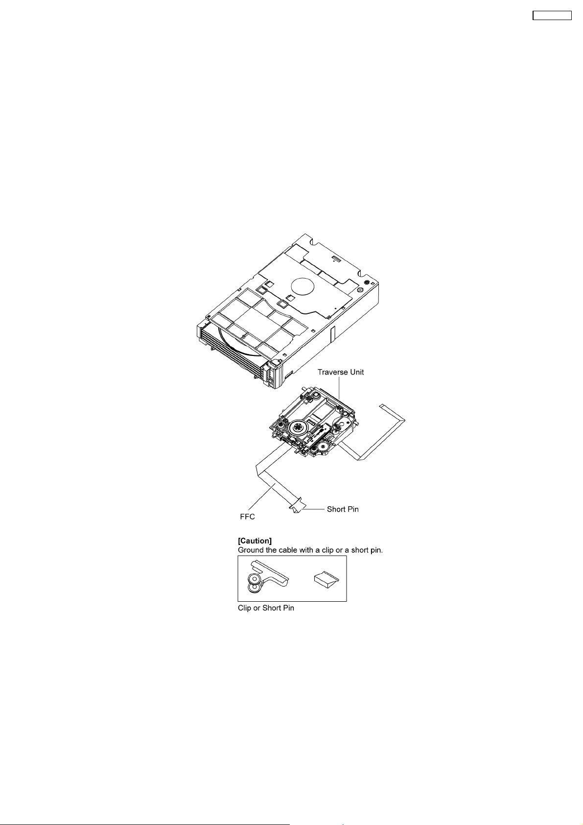
5 Handling Precautions for Traverse Unit
The laser diode in the optical pickup unit may break down due to static electricity of clothes or human body. Special care must be
taken avoid caution to electrostatic breakdown when servicing and handling the laser diode in the traverse unit.
5.1. Cautions to Be Taken in Handling the Optical Pickup Unit
The laser diode in the optical pickup unit may be damaged due to electrostatic discharge generating from clothes or human body.
Special care must be taken avoid caution to electrostatic discharge damage when servicing the laser diode.
1. Do not give a considerable shock to the optical pickup unit as it has an extremely high-precise structure.
2. To prevent the laser diode from the electrostatic discharge damage, the flexible cable of the optical pickup unitremoved should
be short-circuited with a short pin or a clip.
3. The flexible cable may be cut off if an excessive force is applied to it. Use caution when handling the flexible cable.
4. The antistatic FPC is connected to the newoptical pickup unit. After replacing the optical pickupunit and connecting the flexible
cable, cut off the antistatic FPC.
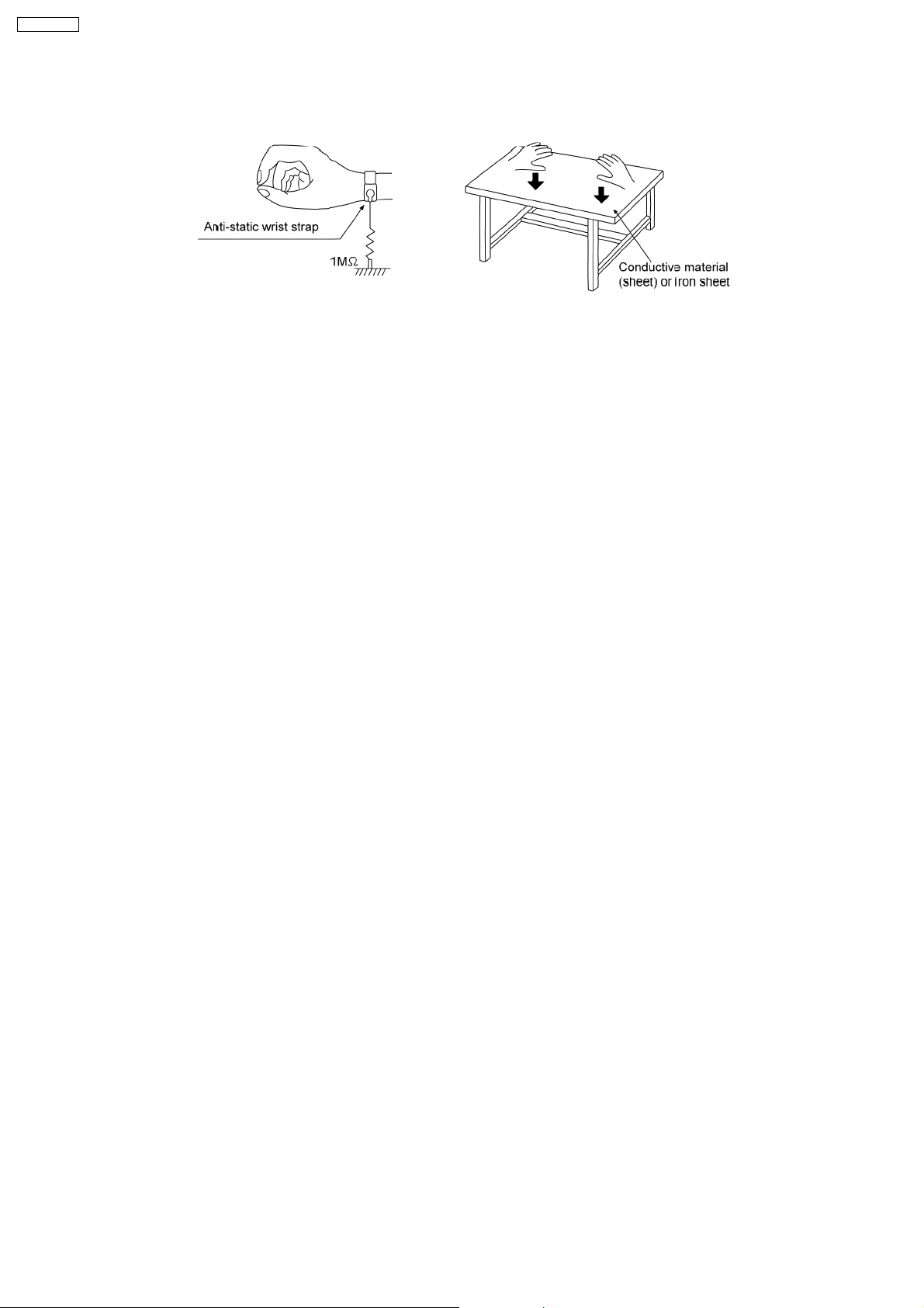
5.2. Grounding for electrostatic breakdown prevention
Some devices such as the DVD player use the optical pickup (laser diode) and the optical pickup will be damaged by static
electricity in the working environment. Proceed servicing works under the working environment where grounding works is
completed.
5.2.1. Worktable grounding
1. Put a conductive material (sheet) or iron sheet on the area where the optical pickup is placed, and ground the sheet.
5.2.2. Human body grounding
1. Use the anti-static wrist strap to discharge the static electricity form your body.
11
SA-VK470EE
12
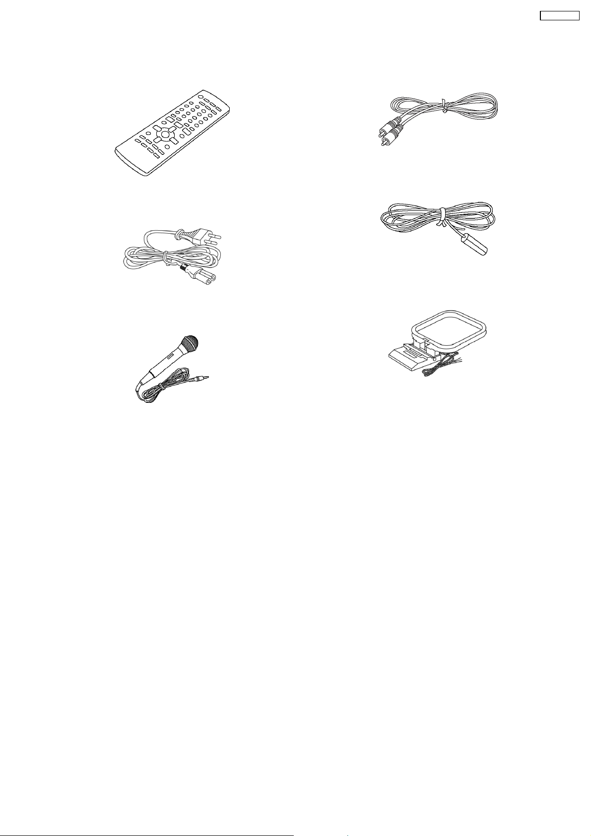
6 Accessories
•
• Note: Refer to “Replacement Parts List” (Section 25) for the part number.
• •
Remote control
AC cord
SA-VK470EE
Video cable
FM indoor antenna
Mic
AM Loop antenna
13
Main unit
SA-VK470EE
7 Operation Procedures
7.1. Main Unit key Button Operations
Main unit
Refer to the numbers in parentheses for page reference. Buttons such as , function the same as the controls on the remote control.
Display panel
AC supply indicator [AC IN ]
This indicator lights when the unit is
connected to the AC mains sup ply.
12 Standby/on switch [ /l]
Press to switch the unit from on
to standby mode or vice versa.
In standby mode, the unit is still
consuming a small amount of power.
[DISPLAY]
Track skip or search, tape
fast-forward or rewind, tape
program sensor (TPS), tune or
preset chann el selection, time
adjustment, manual EQ setting
(MID and TREBLE) .
[ / REW / ], [ / FF / ]
1
Remote control signal
sensor
Disc trays
[, OPEN/CLOSE]
[, EXCHANGE]
[ADVANCED SURROUND]
[ REC, TAPE]
3
[ , TAPE]
USB Port
[FM/AM]
4
5
[EXT-IN]
[, OPEN]
[MANUAL EQ]
MUSIC PORT Jack
Headphone jack
Avoid listening for prolonged
periods of time to prevent hearing
Excessive sound pressure from
earphones and headphones can
cause hearing loss.
Plug type: 3.5 mm stereo
damage.
(not included)
To select the desired display mode
Every time you press the button
Normal Peak hold Re ection
Off
[1 ] to [5 ]
(disc direct play)
6
[, DVD/CD]
[- /+, BASS CONTROL]
7
[H.BASS]
8
[, USB]
[MIC VOL, MIN/MAX]
MIC Jack
[- STOP/ DEMO]
[ /+, VOLUME]
9
Cassette holder
Normal
Indicates strength of the sound in each tonal range
Peak hold
Peak sound value of each sound range (on display for about one second after it occurs).
Re flection
Indicates the strength of the sound in each tonal range (displayed in the opposite direction of normal mode).
14
7.2. Remote Control Key Buttons Operations
Remote control
Remote control
Buttons labelled such as function in exactly the same w
1
Television operations
ay as the buttons on the main unit.
SA-VK470EE
1
Numeric
[ CD MODE , DISC] information
[TOP MENU, DIRECT NAVIGATOR]
Track skip, tape fast-forward or rewind, tape
program sensor (TPS) , tune or preset channel
selection, time adjustment, manual EQ setting.
[,
and selection
5
4
6
8
[FUNCTIONS]
/ REW] , [ , / FF ]
2
[SOUND]
[-CLOCK/TIMER, SLEEP/A.OFF]
[ PLAY/REC ]
9
[FL DISPLAY, DIMMER]
[PLAYMODE, REPEAT]
[]
[, CANCEL]
3
[MENU, PLAYLIST]
[ , , , ], [ OK]
[RETURN, SETUP]
[ , , SLOW/ SEARCH ]
[MUTING]
7
To mute the sound.
Press the button to activate.
Press the button again or
adjust the volume to cancel.
Muting is also cancels
when you switch the unit to
standby.
(Press and hold)
To dim the display panel.
Press and hold again to cancel.
The display is dimmed, but brightens
when you perform some operations.
15
(Press and hold)
This auto off function allows you to turn of f the unit
in disc, t ape or USB mode only af ter left unused for
10 minute s.
Press and hold successively to select AUTO OFF to
activate or cancel the function.
SLEEP 30 SLEEP 60 SLEEP 90 SLEEP120
SLEEPOFF AUTO OFF
The setting is maintained even if the unit is turned off.
If you select tuner or music port as the source, AUTO
OFF turns off. It comes on again when you select disc
or tape.
SA-VK470EE
7.3. Disc Information
7.3.1. Disc Playability (Media)
Discs that can be played
Commercial discs
Disc Logo
Indicated in
these
instructions by
Remarks
DVD-Video
Video CD
CD
Recorded discs
( : Playable, : Not playable)
Recorded on a DVD
Disc Logo
video recorder, etc.
*2
DVD- RAM
DVD- R/RW
DVD- R DL
*3
+R/+RW Necessary
+R DL Necessary
CD-R/RW
*1
High quality movie and music discs.
Music discs with video.
Including SVCD (Conforming to IEC62107).
Music discs.
Recorded on a p ersonal computer, etc.
*4 *8
*5
()
*5
()
*9
Finalizing
Not
necessary
Necessary
Necessary
Necessary
*6
*7
It may not be possible to play all the above-mentioned discs in some cases due to the type of disc, the condition of the recording, the recording
method, or how the files were created.
*1
This unit can play CD-R/RW recorded with CD-DA or Video CD format.
*2
Discs recorded on DVD video recorders or DVD video cameras, etc. using Version 1.1 of the Video Recording Format (a uni fed video
recording standard).
*3
Discs recorded on DVD video recorders or DVD video cameras using Version 1.2 of the Video Recording Format (a uni
*4
Discs recorded on DVD video recorders or DVD video cameras using DVD-Video Format.
*5
Recorded using a format different from DVD-Video Format, therefore, some functions cannot be used.
*6
A process that allows play on compatible equipment. To play a disc that is displayed as Necessary on this unit, the disc must first be
finalized on the device it was recorded on.
*7
Closing the session will also work.
*8
MPEG4 data recorded with the Panasonic SD multi cameras or DVD video recorders [conforming to SD VIDEO speci fications (ASF
standard)/MPEG4 (Simple Pro file) video system/G.726 audio system].
*9
Functions added with DivX Ultra are not supported.
Note about using a DualDisc
The digital audio content side of a DualDisc does not meet the
technical speci cations of the Compact Disc Digital Audio (CD-DA)
format so playback may not be possible.
Discs that cannot be played
Video systems
This unit can play PAL and NTSC, but your television must
match the system used on the disc.
PAL discs cannot be correctly viewed on an NTSC television.
This unit can convert NTSC signals to PAL 60 for viewing on a
PAL television.
fied video rec
ording standard).
Blu-ray, HD DVD, AVCHD discs, DVD-RW version 1.0, DVD-Audio,
DVD-ROM, CD-ROM, CDV, CD-G, SACD, Photo CD, DVD-RAM
that cannot be removed from their cartridge, 2.6 GB and 5.2 GB
DVD-RAM, and Chaoji VCD available on the market including
CVD, DVCD and SVCD that do not conform to IEC62107.
16

7.3.2. Tips for Making Data Discs
Tips for making data discs
Tips for making data discs
When there are more than eight groups, the eighth group onwards
will be displayed on one vertical line in the menu screen.
There may be differences in the display order on the menu screen
and computer screen.
This unit cannot play files recorded using packet write.
DVD- RAM
Discs must conform to UDF 2.0.
DVD- R/RW
Discs must conform to UDF bridge (UDF 1.02/ISO9660).
This unit does not support multi-session. Only the default session
is played.
CD-R/RW
Discs must conform to ISO9660 level 1 or 2 (except for extended
formats).
This unit supports multi-session but if there are many sessions it
takes more time for play to start. Keep the number of sessions to a
minimum to avoid this.
SA-VK470EE
17
Connecting to a portable audio equipment
SA-VK470EE
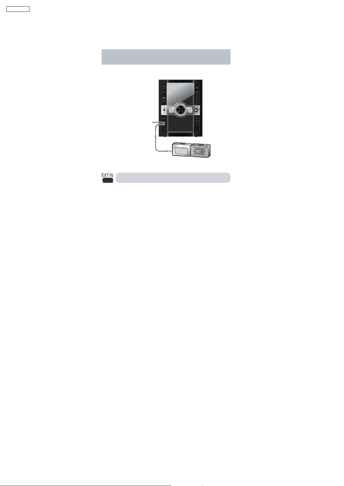
7.4. Using the Music Port
This feature enables you to enjoy music from a portable audio equipment.
Connecting to a portable audio equipment
This feature enables you to enjoy music from a portable audio
equipment.
MUSIC PORT jack
Audio cord
(not included)
Portable audio equipment
(not included)
Switch off the equalizer function (if there is any) of the portable audio
equipment before you plug into the MUSIC PORT jack. Otherwise,
sound from the speaker may be distorted.
IMPORTANT
Reduce the volume of the main unit and the portable audio
equipment before you plug or unplug the equipment into the
MUSIC PORT jack.
1
Plug the audio cord into the MUSIC PORT jack and press
2
Play the por table audio equipment . (See the portable audio
Playing from a portable audio equipment
[EXT-IN] to select MUS IC PORT .
equipment s instruction manual.)
18
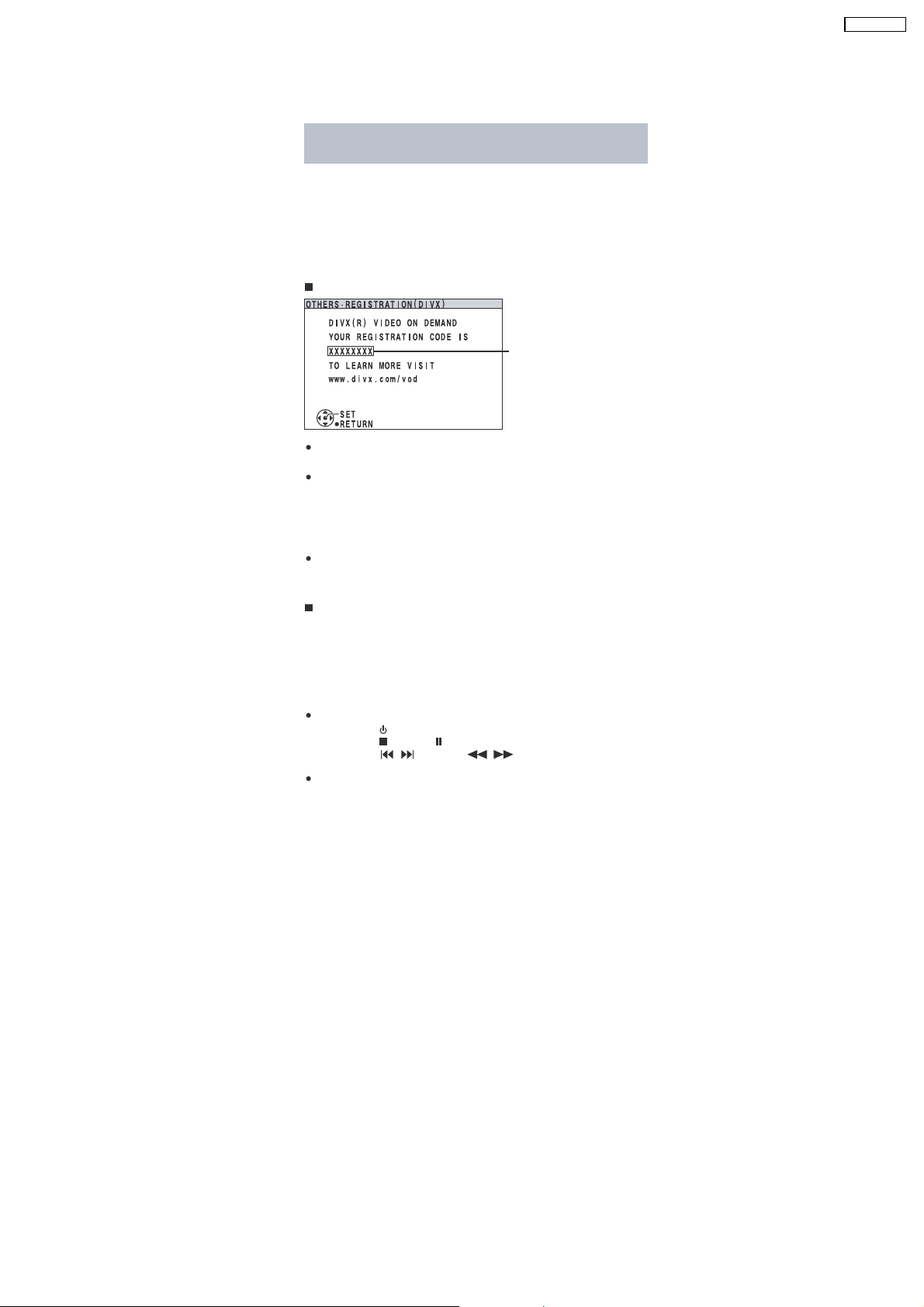
7.5. Divx VOD Content
About DivX VOD content
About DivX VOD content
DivX Video-on-Demand (VOD) content is encrypted for copyright
protection. In order to play DivX VOD content on this unit, you first
need to register the unit.
Follow the online instructions for purchasing DivX VOD content to
enter the unit s registration code and register the unit. For more
information about DivX VOD, visit www.divx.com/vod.
Display the unit s registration code
8 alphanumeric
characters
We recommend that you make a note of this code for future
reference.
After playing DivX VOD content for the rst time, another
registration code is then displayed in REGISTRATION (DIVX) . Do
not use this registration code to purchase DivX VOD content. If you
use this code to purchase DivX VOD content, and then play the
content on this unit, you will no longer be able to play any content
that you purchased using the previous code.
If you purchase DivX VOD content using a registration code
different from this unit s code, you will not be able to play this
content. ( AUTHORIZATION ERROR is displayed.)
Regarding DivX content that can only be played a set
number of times
Some DivX VOD content can only be played a set number of times.
When you play this content, the remaining number of plays is
displayed. You cannot play this content when the number of remaining
plays is zero.
( RENTAL EXPIRED is displayed.)
When playing this content
The number of remaining plays is reduced by one if
y ou press [ ] or press and hold [ SETUP].
y ou press [ ]. [Press [ ] (pause) to pause play.]
y ou pre
ss [, ] (skip) or [, ] (search)
another content or the start of the content being played.
Resume (Stop) function does not work.
etc. and arrive at
SA-VK470EE
19
Connecting and playing a USB mass storage
device
SA-VK470EE
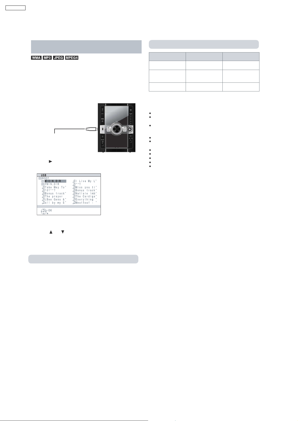
7.6. Connecting and Playing a USB Mass Storage Class Device
device
The USB connectivity enables you to connect and play tracks or les
from USB mass storage devices. Typically, USB memory devices.
(Bulk only transfer)
Preparation
Before connecting any USB mass storage device to the unit, ensure
that the data stored therein has been backed up.
1
Connect the USB mass storage d evice ( not included) .
USB enabled de vice (not included)
It is not recommended to use a USB
extension cable.
The device connected via the cable
will not be recognised by this unit.
Press [ , USB] to select USB .
2
Example:
Connecting and playing a USB mass storage
Supported Formats
File name File extension
Still pictures
Music MP3
Video
*1
It may not be possible to play all the files due to the condition on
how they were created.
*2
For Panasonic D-Snap/DIGA.
Note:
CBI (Control/Bulk/Interrupt) is not supported.
Digital Cameras that use PTP protocol or which require additional
program installation when connected to a PC are not supported.
A device using NTFS file system is not supported.
[Only FAT 12/16/32 (File Allocation Table 12/16/32) file system is
supported].
Depending on the sector size, some files may not work.
It will not operate with Janus enabled MTP (Media Transfer
Protocol) devices.
Maximum folder: 256 folders
Maximum file: 4000 les
Maximum file name: 12 characters
Maximum folder name: 12 characters
Only one memory card will be selected when connecting a
multiport USB card reader. Typically the first memory card inserted.
JPG
WMA
MPEG4
*1
*2
.jpg .jpeg
.mp3
.wma
.asf
3
Adjust the volume of the main unit.
4
Press [ ] or [ ] followed by pressing [OK] to sele ct your
desired item for playback.
For other operating functions, they are similar as those described on
DISC OPERATIONS .
Compatible Devices
Devic es w hic h a r e de ned as USB m as s st o r ag e class :
USB devices that support bulk only transfer.
USB devices that support USB 2.0 full speed.
20
8 Self-Diagnosis and Special Mode Setting
8.1. Service Mode Summary Table
8.1.1. Service Mode Summary Table (For DVD)
The service modes can be activated by pressing various button combination on the main unit and remote control unit.
Below is the summary for the various modes for checking:
Main buttons Remote control unit buttons Application Note
[STOP] [0] Error code display. (Refer to the section
[5] Jitter checking.
[PAUSE] Initial setting of laser drive current.
[FUNCTIONS] DVD laser drive current check. (Refer to the section
[3] CD laser drive current check.
“8.2.1. Service Mode
Table 1” for more
information.)
“8.2.2. Service Mode
Table 2” for more
information.)
SA-VK470EE
[6] Region display and mode. (Refer to the section
[7] Micro-processor firmware version check.
Initialization of the player (factory setting is restored).
Used after replacement of Micro-processor (DV5 LSI) IC, FLASH
ROM IC (IC8651), EEPROM IC (IC8611) and DVD Module
P.C.B.
[8] DVD Module P.C.B. firmware version check. (Refer to the section
[ENTER] DVD Module P.C.B. reset.
Timer 1 check. (Refer to the section
Timer 1 reset.
Timer 2 check.
Timer 2 reset.
“8.2.3. Service Mode
Table 3“for more
information.)
“8.2.4. Service Mode
Table 4“for more
information.)
“8.2.5. Service Mode
Table 5“for more
information.)
Note:
An error code will be canceled if a power supply is turned OFF.
*1: CPPM is the copy guard function beforehand written in the disk for protection of copyrights.
*2: CEC is the consumer electronic control used for high-level user control of HDMI-connected devices.
*3: HDCP is the specification developed to control digital audio & video contents transmission for DVI or HDMI connections.
8.1.2. Service Mode Summary Table (For CR14)
Main buttons Remote control unit buttons Application Note
[STOP] +
/FF/ ]
[
[1]
(In self-diagnostic
mode)
[2]
(In self-diagnostic
mode)
In Self Diagnostic
Mode
- Entering into self-diagnostic mode. (Refer to the section
- Servicing the mechanism unit.
- Servicing the traverse unit.
[1] Reliability 1 (Load) (Refer to the section
[2] Reliability 2 (Cycle)
[3] Reliability 3 (Combi)
“8.3.1. Service Mode
Table 1” for more
information.)
“8.3.2. Service Mode
Table 2” for more
information.)
21

SA-VK470EE
8.2. Service Mode Table (For DVD)
By pressing various button combinations on the main unit and remote control unit, you can activate the various service modes for
checking.
Special Note:
•
• Due to the limitations of the no. characters that can be shown on the FL Display, the “FL Display” button on the remote
• •
control unit can be used to show the two display pages. (Display 1 / Display 2).
•
• Refer to Section 7.2 for the section on “Remote Control Key Buttons Operations”.
• •
22
8.2.1. Service Mode Table 1
SA-VK470EE
Mode Name
Jitter check
Error code
display
Item
Description
Jitter check.
Jitter rate is measured and displayed.
Measurement is repeatedly done in
the cycle of one second. Read error
counter starts from zero upon mode
setting.
When target block data failed to be
read out, the counter advances by one
increment. When the failure is caused
by minor error, it may be corrected
when retried to enable successful
reading.
In this case, the counter advances by
one. When the error persists even
after retry, the counter may jump by
two or more.
FL Display sequence:
Display 1 2.
Error code check
The latest error code stored in the
EEPROM IC is displayed.
Note: Refer to "Section 8.4 DVD Self
Diagnostic Function-Error Code" for
more detailed information on the error
codes.
FL Display
(Display 1)
Jitter Check
Mode
Jitter rate is shown in decimal notation to
one place of decimal.
Focus drive value is shown in hexadecimal
notation.
(Display 2)
Lead
Error
Counter
Error code (play_err) is expressed in the
following convention.
Error code = 0 x DAXX is expressed: DVDnn U12
Error code = 0 x DBXX is expressed: DVDnn H12
Error code = 0 x DXXX is expressed: DVDnn F123
Error code = 0 x 0000 is expressed: DVDnn F--* "xx" denotes the error code
Jitter Rate
Focus Drive
Value
U / H / F
Key Operation
Front Key
In STOP (no disc) mode,
press [STOP] button on the
main unit, and [5] button on
the remote control unit.
Press [STOP] button to
exit.
Press [FL Display] on
remote control unit for next
page (FL Display).
In STOP (no disc) mode,
press [STOP] button on the
main unit, and [0] button on
the remote control unit. * With
pointing of cursor up and
down on display.
Cancelled automatically
5 seconds later.
To exit, press [POWER]
button on main unit or
remote control.
Initial setting
of laser drive
current
Initial setting of laser drive current.
Initial current value for the DVD laser
and CD laser is separately saved in
the EEPROM IC.
FL Display sequence:
Display 1 2.
(Display 1)
Laser Current
Measurement
The value denotes the current in decimal
notation.
(Display 2)
The above example shows the initial
current is XXXmA and YYYmA for CD
laser and DVD laser respectively when
the laser is switched on.
Mode
CD
Laser
Identify
as LDO
mode
DVD Laser
In STOP (no disc) mode,
press [STOP] button on the
main unit, and [PAUSE]
button on the remote
control unit.
Cancelled automatically
5 seconds later.
Press [FL Display] on
remote control unit for next
page (FL Display) on values
of laser drive current.
23
SA-VK470EE
8.2.2. Service Mode Table 2
DVD laser
drive current
measurement
CD laser drive
current
measurement
Item
DescriptionMode Name
DVD laser drive current measurement.
DVD laser drive current is measured
and the result is displayed together
with the initial value stored in the
EEPROM IC.
After the measurement, DVD laser
emission is kept on. It is turned off
when POWER key is switched off.
FL Display sequence:
Display 1 2.
CD laser drive current measurement.
CD laser drive current is measured
and the result is displayed together
with the initial value stored in the
EEPROM IC.
After the measurement, CD laser
emission is kept on. It is turned off
when POWER key is switched off.
FL Display sequence:
Display 1 2.
FL Display
(Display 1)
DVD laser current
measurement mode
The value denotes the current in decimal
notation.
(Display 2)
DVD
DVD
Laser
Initial Value
The above example shows the initial
current is XXXmA and the measured
value is YYYmA.
(Display 1)
CD Laser Current
Measurement Mode
The value denotes the current in decimal
notation.
(Display 2)
Laser
Value
Identify as
LDD mode
Key Operation
Front Key
In STOP (no disc) mode,
press [STOP] button on the
main unit, and
[FUNCTIONS] button on
the remote control unit.
Cancelled automatically
5 seconds later.
Press [FL Display] on
remote control unit for next
page (FL Display) on values
of dvd drive current.
In STOP (no disc) mode,
press [STOP] button on
the main unit, and [3]
button on the remote
control unit.
Cancelled automatically
5 seconds later.
Press [FL Display] on
remote control unit for next
page. (FL Display)
CD
Laser Initial
Value
The above example shows the initial current
is XXXmA and the measured value is
YYYmA.
CD Laser
Value
24
8.2.3. Service Mode Table 3
SA-VK470EE
Micro-processor
firmware version
display &
EEPROM
checksum
display.
Item
DescriptionMode Name
Micro-processor firmware version
display & EEPROM checksum display.
EEPROM checksum is only available
due to existence of EEPROM IC.
Note: Condition 1/2/3 shows the state
of EEPROM IC. It is indicated in
Display 2.
FL Display sequence:
Display 1 2 3.
FL Display
(Display 1)
(Display 2)
Opecon
Version
(Condition1)
If the version of the EEPROM does not match,
[NG] is displayed.
(Condition 2)
(a) If there is NO EEPROM header string
OR
(b) If there is no EEPROM (no data is received
by Micro-processor), [NO] is displayed.
(Condition 3)
EEPROM
Checksum
(If applicable,
refer below.)
Key Operation
Front Key
In STOP (no disc)
mode, press [STOP]
button on the main unit,
and [7] button on the
remote control unit.
Cancelled automatically
5 seconds later.
Initialization
mode
Region display
Initialization.
User settings are cancelled and player
is initialized to factory setting.
It is necessary when after replacement
of Micro-processor (DV5 LSI) IC,
FLASH ROM IC (IC8651), EEPROM
IC (IC8611) & DVD Module P.C.B.
Region code display, TV broadcasting
system & the model no. information.
Note: Refer to Fig. 8.1 for "Video
Design Information".
If the EEPROM version matches, checksum
[YYYY] is displayed.
(Display 3)
Model
No.
Information
N: NTSC / 6: PAL60
N: no PAL / P: PAL
Region No.: 0-8
Press [FL Display] button on
remote control unit for next
page. (FL Display)
In STOP (no disc)
mode, press [STOP]
button on the main unit,
and [ 10] button on the
remote control unit.
Cancelled automatically
5 seconds later.
In STOP (no disc)
mode, press [STOP]
button on the main unit,
and [6] button on the
remote control unit.
Cancelled automatically
5 seconds later.
25
SA-VK470EE
Product
OSD
Default
English
OSD Menu Language
English, Spanish,
Model Series
P, PC, PX
Country Region
USA, Canada, PX
Region
Code
1
TV Broadcasting
System
NTSC
Signal System
(Default)
NTSC (*A)
Region Display
(Default)
1PN
Canadian, French
(S) Japanese, English
Japan
2
NTSC
NTSC (*A)
2PN
Japanese
English, French, German,
E
Europe
2
PAL
PAL (*C)
2P6
English
Spanish, Polish, Russian,
Czech, Hungarian
English, French, German,
EB, EG
Europe
2
PAL
PAL (*C)
2P6
English
Italian, Spanish, Polish,
Swedish, Dutch
English, French, German,
GC, GS
Middle East
2
PAL
PAL (*C)
2P6
English
Spanish, Polish, Russian,
Czech, Hungarian
GCS, GD, English, Traditional Chinese
GT, GCT
GN
South East Asia,
Korea, Taiwan
New Zealand,
3
4
Australia
PL, GCP, LB
Central/South/
4
Latin America
PAL
NTSC
PAL
NTSC
NTSC (*B)
PAL (*C)
NTSC (*D)
3PN
4P6
4PN
English
English
English
English, French, German,
Italian, Spanish, Polish,
Swedish, Dutch
English, Spanish, French,
Brazilian Portuguese
English, French, German,
EE
CIS
5
SECAM
PAL (*C)
5P6
English
Spanish, Polish, Russian,
Czech, Hungarian
GK English, Simplified Chinese
China
6
PAL
NTSC (*B)
6PN
English
NTSC (*A)
Source Output
Screen Saver NTSC
NTSC disc NTSC
PAL disc
PAL (DVD-V)
NTSC (DVD-A/VCD)
NTSC (*D)
Source Output
Screen Saver NTSC
NTSC disc NTSC
PAL disc NTSC
NTSC (*B)
Source Output
Screen Saver NTSC
NTSC disc
NTSC (default)
PAL60
PAL disc PAL
Explanation of Display
Figure 8.1 Video Design Information
PAL (*C)
Source Output
Screen Saver PAL
NTSC disc
PAL60 (default)
NTSC
PAL disc PAL
Individual Model Code
N: If NTSC disc is played, NTSC output.
6: If NTSC disc is played, PAL60 output.
Can play PAL disc
Region code
26
8.2.4. Service Mode Table 4
SA-VK470EE
Mode Name
DVD Module
P.C.B. firmware
version display
DVD Module
P.C.B. Reset
Item
Description
DVD Module P.C.B. firmware version
is displayed on the FL Display.
The firmware version can be updated
using recovery disc.
Note: It is necessary to check for
firmware version before carrying out
the version up using the disc.
To reset DVD Module P.C.B.
This process is used when the DVD
Module P.C.B. or FLASH ROM
IC is replaced with a new one.
FL Display
System controller
generation
Region No.: 0-8
System
controller
version
Destination
Key Operation
Front Key
In STOP (no disc)
mode, press [STOP]
button on the main unit,
and [8] button on the
remote control unit.
Cancelled automatically
5 seconds later.
While in initialization
mode, press & hold
[STOP] button on the main
unit, follow by [ENTER]
button on the remote
control unit.
Cancelled automatically
5 seconds later.
27
SA-VK470EE
8.2.5. Service Mode Table 5
Timer 1 check
Timer 1 reset
Item
DescriptionMode Name
Timer 1 check
Laser operation timer is measured
separately for DVD laser and CD laser.
FL Display sequence:
Display 1 2.
Timer 1 reset
Laser operation timer of both DVD
laser and CD laser is reset all at once.
FL Display
(Display 1)
DVD laser usage time
Shown to the above is DVD laser usage
time, and to the below is CD laser usage
time.
Time is shown in 4 digits of decimal notation
in a unit of 10 hours.
"0000" will follow "9999". (DVD laser)
(Display 2)
CD laser usage time
Time is shown in 4 digits of decimal notation
in a unit of 10 hours.
"0000" will follow "9999". (CD laser)
Time is shown in 4 digits of decimal notation
in a unit of 10 hours.
It will clear to "0000" upon reset.
Key Operation
Front Key
In STOP (no disc)
mode, press [STOP]
button on the main unit,
and [ ] button on the
remote control unit.
Cancelled automatically
5 seconds later.
Press [FL Display] button for
next page of FL Display.
While displaying Timer 1
data, press [STOP] button
on the main unit, and [ ]
button on the remote
control unit.
Cancelled automatically
5 seconds later
Timer 2 check
Timer 2 reset
Timer 2 check
Spindle motor operation timer
Timer 2 reset
Spindle motor operation timer
Time is shown in 5 digits of decimal notation in
a unit of 1 hour.
"00000" will follow "99999".
Time is shown in 5 digits of decimal notation in
a unit of 1 hour.
It will be cleared to "00000" upon activating
this.
In STOP (no disc)
mode, press [STOP]
button on the main unit,
and [ ] button on the
remote control unit.
Cancelled automatically
5 seconds later.
While displaying Timer 2
data, press [STOP] button
on the main unit, and [ ]
button on the remote
control unit.
Cancelled automatically
5 seconds later.
28
SA-VK470EE
8.2.6. Optical Pick-up Self-Diagnosis
The optical pickup self-diagnosis function and tilt adjustment check function have been included in this unit. When repairing, use
the following procedure for effective self-diagnosis and tilt adjustment. Be sure to use the self-diagnosis function before replacing
the optical pickup when “NO DISC” is displayed. As a guideline, you should replace the optical pickup when the value of the laser
drive current is more than the specified value.
Note:
Press the power button to turn on the power, and check the value within three minutes before the unit warms up. (Otherwise,
the result will be incorrect.)
"NO DISC" is displayed, unit
does not play smoothly, etc.
Check the laser drive current.
Value is more than
37 (DVD), 41 (CD).
Replace the traverse unit.
(Refer to the section "OPTICAL
PICKUP REPLACEMENT
PROCEDURE" in this Guide.)
Initialize the main unit.
Use the optical pickup self-diagnosis function.
Method: With no disc in the main unit:
• Press the "FUNCTIONS" button on the remote
control unit while pressing the "STOP"
button on the main unit. (DVD)
•Press the "3" button on the remote
control unit while pressing the "STOP"
button on the main unit. (CD)
[Display content (display1/display2)]
/
LDD (DVD)
Factory setting Present value
LDC (CD)
/
Factory setting Present value
Replace with a new optical pickup if the present
value is more than 37 (DVD), 41 (CD).
Cause: Damage due to static electricity
during replacement.
29
SA-VK470EE
8.3. Service Mode Table (For CR14)
8.3.1. Service Mode Table 1
Mode Name
Self-Diagnostic
Mode
Service Mode 1
Service Mode 2
Item
Description
To enter into self-diagnostic checking
for CR14 mechanism.
To unlock the mechanism unit for
service.
In this mode, the disassembly of CR14
can be carry out. (Refer to original
service manual for CR14)
1. All trays are set to "STOCK" position.
2. Mechanism set to tray 1.
3. Cam gear set to "HOME" position.
To unlock the traverse unit for service.
In this mode, traverse unit can be
disassembled. (Refer to original
service manual for CR14)
1. Tray 5 set to "Play" position.
2. Mechanism set to tray 5.
3. Cam gear set to "HOME" position.
FL Display
Key Operation
Front Key
In DVD/CD mode (ensure no disc is
inserted):
Press and hold [STOP] button for five
seconds, followed by [ /FF/ ]
button on the main unit.
To exit, press [ , AC IN] button on
main unit or remote control unit.
In self-diagnostic mode, press [1]
button on main unit.
To exit, power off the main unit
Press [EXCHANGE] on main unit
for error code.
In self-diagnostic mode, press [2]
button on main unit.
To exit, power off the main unit
Press [EXCHANGE] on main unit
for error code.
(Refer to section 8.6.1. for information)
/l
30
 Loading...