

Panasonic SART-70-EB Service manual
ORDER NO. MD0605187C2
Recordable DVD Home Theater System
SA-RT70EB
SA-RT70EG
Vol. 1
Colour
(S).......................Silver Type
Specification
n AMPLIFIER SECTION
RMS Output Power: Dolby Digital Mode
Front: 90 W per channel (4 Ω ), 1 kHz,
10%, THD
Center: 320 W (4 Ω), 1 kHz, 10%, THD
Surround: 90 W per channel (4 Ω ), 1 kHz,
10%, THD
Subwoofer: 320 W (4 Ω), 100 Hz, 10%, THD
Total RMS Dolby Digital Mode
Power:
DIN Output Power: Dolby Digital Mode
1000 W
Front: 65 W per channel (4 Ω), 1 kHz,
1%, THD
Center: 220 W (4 Ω ), 1 kHz, 1%, THD
Surround: 65 W per channel (4 Ω), 1 kHz,
1%, THD
Subwoofer: 220 W (4 Ω), 100 Hz, 1%, THD
Total DIN Dolby Digital Mode
Power:
Imput sensitivity/input impedance:
MUSIC PORT: 100mV/4.7kΩ
© 2006 Matsushita Electric Industrial Co., Ltd. All
rights reserved. Unauthorized copying and
distribution is a violation of law.
700 W
A
A
A
A
SA-RT70EB / SA-RT70EG
n FM TUNER SECTION
Frequency range: 87.50 to 108 MHz (50 kHz step)
ntenna terminals: 75 Ω unbalanced
n AM TUNER SECTION
Frequency range: 522-1629 kHz (9 kHz step)
n RECORDER SECTION
Recording system:
DVD-RAM: DVD Video Recording
format
DVD-R: DVD-Video format
DVD-R DL (Dual Layer): DVD-
Video format
DVD-RW: DVD-Video format
+R
+R DL (Dual Layer)
+RW
Recordable discs
DVD-RAM: Ver. 2.0
Ver. 2.1/3X-SPEED DVD-RAM Revision 1.0
Ver. 2.2/5X-SPEED DVD-RAM Revision 2.0
DVD-R: for General Ver. 2.0
for General Ver. 2.0/4X-SPEED DVD-R Revision 1.0
for General Ver. 2.x/8X-SPEED DVD-R Revision 3.0
for General Ver. 2.x/16X-SPEED DVD-R Revision 6.0
for DL Ver. 3.0
for DL Ver. 3.x/4X-SPEED DVD-R for DL Revision 1.0
DVD-RW: Ver. 1.1
Ver. 1.x/2X-SPEED DVD-RW Revision 1.0
Ver. 1.x/4X-SPEED DVD-RW Revision 2.0
Ver. 1.x/6X-SPEED DVD-RW Revision 3.0
+R: Ver. 1.0
Ver. 1.1
Ver. 1.2
Ver. 1.3
for DL Ver. 1.0
+RW: Ver. 1.1
Ver. 1.2/4X-SPEED
Recording time Maximum 8 hours (using 4.7 GB
disc)
XP: Approx. 1 hour, SP: Approx. 2 hours
LP: Approx. 4 hours, EP: Approx. 6 hours/8 hours
Playable discs
DVD-RAM: DVD Video Recording format
DVD-R: DVD-Video format, MP3, JPEG (EB only)
DVD-R: DVD-Video format, MP3, JPEG, DivX (EG only)
DVD-R DL (Dual Layer): DVD-Video format
DVD-RAM: DVD-Video format, DVD Video Recording format
+R, +R DL (Double Layer), +RW
DVD-Video, DVD-Audio, CD-Audio (CD-DA), Video CD,
CD-R/CD-RW (CD-DA, Video CD, SVCD, MP3, JPEG formatted
discs) (EB only)
CD-R/CD-RW (CD-DA, Video CD, SVCD, MP3, JPEG, DivX
formatted discs) (EG only)
SVCD
Optical pick-up: System with 1 lens, 2 integration
units
(662 nm wavelength for DVDs, 780 nm wavelength for CDs)
LASER Specification
Class 1 LASER Product
Wave Length: 780 nm (CDs), 662 nm (DVDs)
Laser Power: No hazardous radiation is emitted
with the safety protection
udio
Recording system: Dolby Digital 2ch
udio in: AV1/AV2 (21 pin), AV3 (pin jack)
Input level: Standard: 0.5 Vrms,
Full scale: 2.0 Vrms at 1 kHz
Input impedance: More than 10 kΩ
udio out: AV1/AV2 (21 pin), Audio Out (pin
jack)
Output level: Standard: 0.5 Vrms,
Full scale: 2.0 Vrms at 1 kHz
Output impedance: Less than 1 kΩ
Video
Video system: PAL colour signal, 625 lines, 50
fields
NTSC colour signal, 525 lines, 60
fields
Recording system: MPEG2 (Hybrid VBR)
Video in (PAL/NTSC ):
AV1/AV2 (21 pin), AV3 (pin jack) 1 Vp-p 75 Ω, termination
S-Video in (PAL/NTSC ):
AV2 (21 pin), AV3 (S terminal) 1 Vp-p 75 Ω, termination
Video out (PAL/NTSC):
AV1/AV2 (21 pin), Video Out (pin jack) 1 Vp-p 75 Ω , termination
S-Video out (PAL/NTSC):
AV1 (21 pin), S-Video Out (S terminal) 1 Vp-p 75 Ω , termination
RGB out (PAL/NTSC):
AV1 (21 pin) 0.7 Vp-p (PAL) 75 Ω , termination
Component video output (NTSC 480p/480i, PAL 576p/576i)
Y: 1.0 Vp-p 75 Ω, termination
PB:0.7Vp-p75Ω, termination
PR:0.7Vp-p75Ω, termination
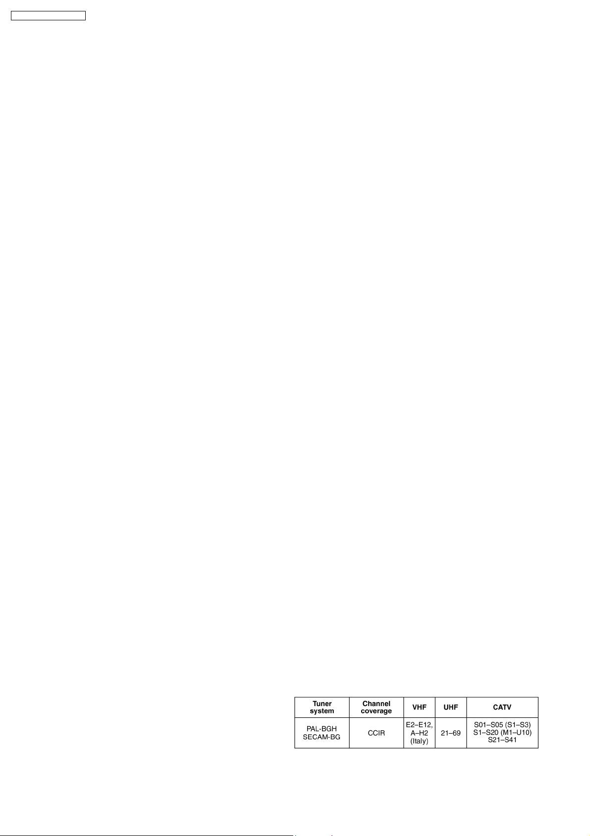
Television system
(For EB only)
Tuner system: PAL-I
Channel coverage: UHF:21-68
(For EG only)
RF converter output: Not provided
2
DV input IEEE 1394 Standard, 4 pin : 1 pc
n GENERAL
Region code: #2
Operating temperature range: 5to40°C
Operation humidity range: 10 to 80% RH (no condensation)
Power supply: AC 230 to 240 V, 50 Hz
Power consumption: 145 W
Dimensions (W x H x D): 430 mm x 75 mm x 385 mm
Mass: Approx. 5.3 kg
(Dimensions and Mass do not include the speakers.)
Notes :
1. Specifications are subject to change without notices. Mass and
dimensions are approximate.
2. Connect the supplied speakers and subwoofer to this unit only.
Do not attempt to connect the supplied speakers and subwoofer to
the external amplifier and so on.
3. Total harmonic distortion is measured by the digital spectrum
analyzer.
SA-RT70EB / SA-RT70EG
CONTENTS
Page Page
1 Safety Precautions 5
1.1. General Guidelines
1.2. Caution for AC Cord
1.3. Before Repair and Adjustment
1.4. Protection Circuitry
2 Prevention of Electro Static Discharge (ESD) to
Electrostatically Sensitive (ES) Devices
3 Precaution of Laser Diode
4 Service caution based on legal restrictions
4.1. General description about Lead Free Solder (PbF)
5 Service Navigation
5.1. Service Information
5.2. Caution for DivX (Except EB)
6 New Feature
6.1. About DivX
7 Accessories 17
5
8 Operating Instructions Procedures
6
7
7
8
9
10
10
11
11
11
12
12
8.1. Remote Control Operation
8.2. Main Unit Operation
8.3. Disc Information
8.4. Video connections
8.5. Use of Music Port
9 Operation Instructions
9.1. (DVD) Taking out the Disc from RAM-Drive Unit when the
Disc cannot be ejected by OPEN/CLO SE button
10 Service Mode
10.1. (DVD) Self-Diagnosis and Special Mode Setting
11 Assembling and Disassembling
11.1. Caution
11.2. Disassembly flow chart
3
18
18
19
20
23
26
27
27
28
28
36
36
37
SA-RT70EB / SA-RT70EG
11.3. Main Parts Location Diagram 37
11.4. Disassembly of Top Cabinet
11.5. Disassembly of Front Panel
11.6. Disassembly of Volume P.C.B, Panel R P.C.B and Panel
L P.C.B
11.7. Disassembly of Rear Panel
11.8. Disassembly of Audio Main P.C.B
11.9. Disassembly of D-AMP Shield
11.10. Disassembly of Power P.C.B
11.11. Disassembly of RAM/Digital P.C.B. Module
11.12. Disassembly of DV P.C.B
11.13. Disassembly of D-AMP P.C.B
11.14. Disassembly of Main P.C.B
12 Service Fixture & Tools
13 Measurements and Adjustments
13.1. Service Positions
13.2. Caution for Replacing Parts
13.3. Standard Inspection Specifications after Making Repairs
14 Miscellane ous
14.1. Abbreviations
15 Voltage Measurement and Waveform Chart
15.1. Voltage Measurement
15.2. Waveform
16 Wiring Connection Diagram
17 Block Diagram
18 Notes of Schematic Diagram
38
38
19 Schematic Diagram
19.1. Main Circuit
38
39
39
40
40
40
41
41
42
43
44
44
52
53
54
54
56
56
65
19.2. Power Circuit
19.3. Volume Circuit, Tuner Extent Circuit, DV Circuit and Panel
L Circuit
19.4. D-AMP Circuit
19.5. Audio Main Circuit
19.6. Panel R Circuit
20 Printed Circuit Board
20.1. Main P.C.B
20.2. Power P.C.B, Volume P.C.B, Tuner Extent P.C.B, DV
P.C.B and Panel L P.C.B
20.3. D-AMP P.C.B
20.4. Audio Main P.C.B and Panel R P.C.B
21 Illustration of IC's, Transistors and Diodes
22 Terminal Function of IC's
22.1. IC801 (C2CBHG000226) MICRO PROCESSOR
23 Exploded Views
23.1. Cabinet Parts Location
23.2. Packaging
24 Replacement Parts List
69
71
77
79
79
87
88
89
91
95
97
97
98
99
100
101
102
102
103
103
105
107
4
SA-RT70EB / SA-RT70EG
1 Safety Precautions
1.1. General Guidelines
1. When servicing, observe the original lead dress. If a short circuit is found, replace all parts which have been overheated or
damaged by the short circuit.
2. After servicing, ensure that all the protective devices such as insulation barriers, insulation papers shields are properly installed.
3. After servicing, check for leakage current checks to prevent from being exposed to shock hazards.
1.1.1. Leakage Current Cold Check
1. Unplug the AC cord and connect a jumper between the two prongs on the plug.
2. Using an ohmmeter measure the resistance value, between the jumpered AC plug and each exposed metallic cabinet part on
the equipment such as screwheads, connectors, control shafts, etc. When the exposed metallic part has a return path to the
chassis, the reading should be between 1MΩ and 5.2Ω .
When the exposed metal does not have a return path to the chassis, the reading must be
.
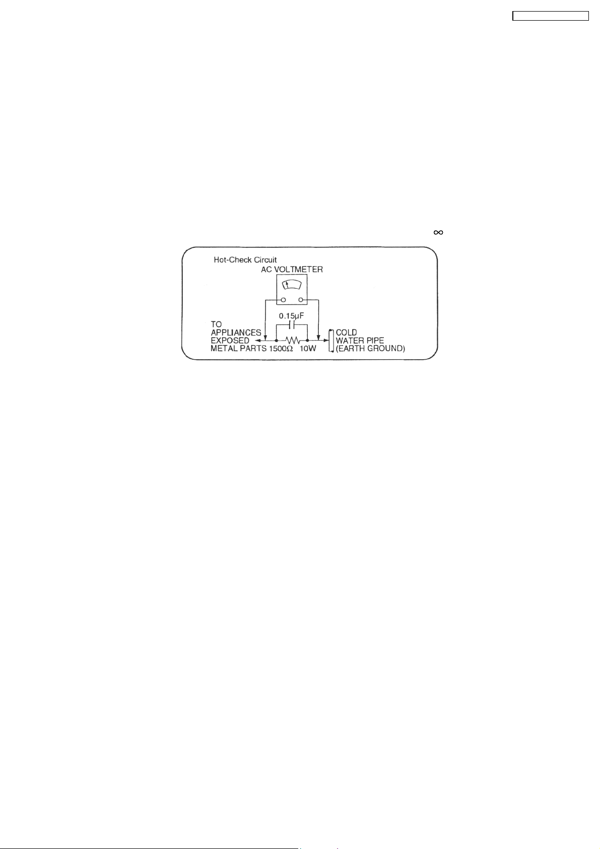
Figure 1
1.1.2. Leakage Current Hot Check (See Figure 1)
1. Plug the AC cord directly into the AC outlet. Do not use an isolation transformer for this check.
2. Connect a 1.5kΩ, 10 watts resistor, in parallel with a 0.15µF capacitors, between each exposed metallic part on the set and a
good earth ground such as a water pipe, as shown in Figure 1.
3. Use an AC voltmeter, with 1000 ohms/volt or more sensitivity, to measure the potential across the resistor.
4. Check each exposed metallic part, and measure the voltage at each point.
5. Reverse the AC plug in the AC outlet and repeat each of the above measurements.
6. The potential at any point should not exceed 0.75 volts RMS. A leakage current tester (Simpson Model 229 or equivalent) may
be used to make the hot checks, leakage current must not exceed 1/2 milliamp. should the measurement is outside of the limits
specified, there is a possibility of a shock hazard, and the equipment should be repaired and re-checked before it is returned
to the customer.
5
SA-RT70EB / SA-RT70EG
1.2. Caution for AC Cord
6

SA-RT70EB / SA-RT70EG
1.3. Before Repair and Adjustment
Disconnect AC power, discharge Power Supply Capacitors C1110, C1121, C1122, C1124, C1125, C1126, C1127, C2702 & C2706
through a 10Ω , 1W resistor to ground.
DO NOT SHORT-CIRCUIT DIRECTLY (with a screwdriver blade, for instance), as this may destroy solid state devices.
After repairs are completed, restore power gradually using a variac, to avoid overcurrent.
· Current consumption at AC 230 V, 50 Hz in NO SIGNAL mode (at volume minimum) should be ~650 mA. (EB)
· Current consumption at AC 230-240 V, 50 Hz in NO SIGNAL mode (at volume minimum) should be ~650 mA. (EG)
1.4. Protection Circuitry
The protection circuitry may have operated if either of the following conditions are noticed:
· No sound is heard when the power is turned on.
· Sound stops during a performance.
The function of this circuitry is to prevent circuitry damage if, for example, the positive and negative speake r connection wires are
"shorted", or if speaker systems with an impedance less than the indicated rated impedance of the amplifier are used.
If this occurs, follow the procedure outlines below:
1. Turn off the power.
2. Determine the cause of the problem and correct it.
3. Turn on the power once again after one minute.
Note:
When the protection circuitry functions, the unit will not operate unless the power is first turned off and then on again.
7
SA-RT70EB / SA-RT70EG
2 Prevention of Electro Static Discharge (ESD) to
Electrostatically Sensitive (ES) Devices
Some semiconductor (solid state) devices can be damaged easily by electricity. Such components commonly are called
Electrostatically Sensitive (ES) Devices. Examples of typical ES devices are integrated circuits and some field-effect transistors and
semiconductor “chip” components. The following techniques should be used to help reduce the incidence of component damage
caused by electro static discharge (ESD).
1. Immediately before handling any semiconductor component or semiconductor-equiped assembly, drain off any ESD on your
body by touching a known earth ground. Alternatively, obtain and wear a commercially available discharging ESD wrist strap,
which should be removed for potential shock reasons prior to applying power to the unit under test.
2. After removing an electrical assembly equiped with ES devices, place the assembly on a conductive surface such as aluminium
foil, to prevent electrostatic charge build up or exposure of the assembly.
3. Use only a grounded-tip soldering iron to solder or unsold er ES devices.
4. Use only an anti-static solder remover device. Some solder removal devices not classified as “anti-static (ESD protected)” can
generate electrical charge to damage ES devices.
5. Do not use freon-propelled chemicals. These can generate electrical charges sufficie nt to damage ES devices.
6. Do not remove a replacement ES device from its protective package until immediately before you are ready to install it. (Most
replacement ES devices are packaged with leads electrically shorted together by conductive foam, aluminium foil or
comparable conductive material).
7. Immediately before removing the protective material from the leads of a replacement ES device, touch the protective material
to the chassis or circuit assembly into which the device will be installe d.
Caution
Be sure no power is applied to the chassis or circuit, and observe all other safety precautions.
8. Minimize body motions when handling unpackaged replacement ES devices. (Otherwise harmless motion such as the brushing
together of your clothes fabric or the lifting of your foot from a carpeted floor can generate static electricity (ESD) sufficient to
damage an ES device).
8
SA-RT70EB / SA-RT70EG
3 Precaution of Laser Diode
CAUTION :
This product utilizes a laser diode with the unit turned "ON", invisible laser radiation is emitted from the pick up lens.
Wavelength : 662nm (DVD)/780nm(CD)
Maximum output radiation power from pick up : 100 µW/VDE
Laser radiation from pick up unit is safety level, but be sure the followings:
1. Do not disassemble the optical pick up unit, since radiation from exposed laser diode is dangerous.
2. Do not adjust the variable resistor on the pick up unit. It was already adjusted.
3. Do not look at the focus lens using optical instruments.
4. Recommend not to look at pick up lens for a long time.
ACHTUNG :
Dieses Produkt enthält eine Laserdiode. Im eingeschalteten Zustand wird unsichtbare Laserstrahlung von der Lasereinheit
abgestrahlt.
Wellenlänge : 662nm (DVD)/780nm (CD)
Maximale Strahlungsleistung der Lasereinheit :100 µW/VDE
Die Strahlung an der Lasereinheit ist ungefährlich, wenn folgende Punkte beachtet werden:
1. Die Lasereinheit nicht zerlegen, da die Strahlung an der freigelegten Laserdiode gefährlich ist.
2. Den werkseitig justierten Einstellregler der Lasereinhit nicht verstellen.
3. Nicht mit optischen Instrumenten in die Fokussierlinse blicken.
4. Nicht über längere Zeit in die Fokussierlinse blicken.
ADVARSEL :
I dette a apparat anvendes laser.
CAUTION!
THIS PRODUCT UTILIZES A LASER.
USE OF CONTROLS OR ADJUSTMENTS OR PERFORMANCE OF PROCEDURES OTHER THAN THOSE SPECIFIED HEREIN MAY RESULT
IN HAZARDOUS RADIATION EXPOSURE.
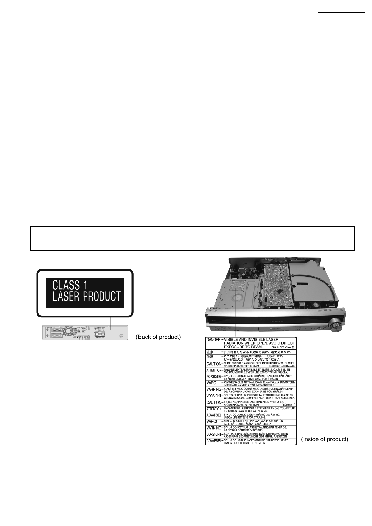
n Use of Caution Labels
9
SA-RT70EB / SA-RT70EG
4 Service caution based on legal restrictions
4.1. General description about Lead Free Solder (PbF)
The lead free solder has been used in the mounting process of all electrical components on the printed circuit boards used for this
equipment in considering the globally environmental conservation.
The normal solder is the alloy of tin (Sn) and lead (Pb). On the other hand, the lead free solder is the alloy mainly consists of tin
(Sn), silver (Ag) and Copper (Cu), and the melting point of the lead free solder is higher approx.30 degrees C (86°F) more than that
of the normal solder.
Definition of PCB Lead Free Solder being used
The letter of “PbF” is printed either foil side or components side on the PCB using the lead free solder.
(See right figure)
Service caution for repair work using Lead Free Solder (PbF)
· The lead free solder has to be used when repairing the equipment for which the lead free solder is used.
(Definition: The letter of “PbF” is printed on the PCB using the lead free solder.)
· To put lead free solder, it should be well molten and mixed with the original lead free solder.
· Remove the remaining lead free solder on the PCB cleanly for soldering of the new IC.
· Since the melting point of the lead free solder is higher than that of the normal lead solder, it takes the longer time to melt
the lead free solder.
· Use the soldering iron (more than 70W) equipped with the temperature control after setting the temperature at 350±30
degrees C (662±86°F).
Recommended Lead Free Solder (Service Parts Route.)
· The following 3 types of lead free solder are available through the service parts route.
RFKZ03D01K-----------(0.3mm 100g Reel)
RFKZ06D01K-----------(0.6mm 100g Reel)
RFKZ10D01K-----------(1.0mm 100g Reel)
Note
* Ingredient: tin (Sn), 96.5%, silver (Ag) 3.0%, Copper (Cu) 0.5%, Cobalt (Co) / Germanium (Ge) 0.1 to 0.3%
10
5 Service Navigation
5.1. Service Information
SA-RT70EB / SA-RT70EG
5.2. Caution for DivX (Except EB)
11
SA-RT70EB / SA-RT70EG
6 New Feature
6.1. About DivX
6.1.1. General
DivX is a new video compressing format that is applied MPEG4 technology to improve image quality and the compressibil ity, andit
is developed by the DivXNetworks, Inc., Video file of high resolution and the high picture quality can be made though it is a
highcompressibility.
DivX codec is necessary for converting video to DivX file and .playback files made.
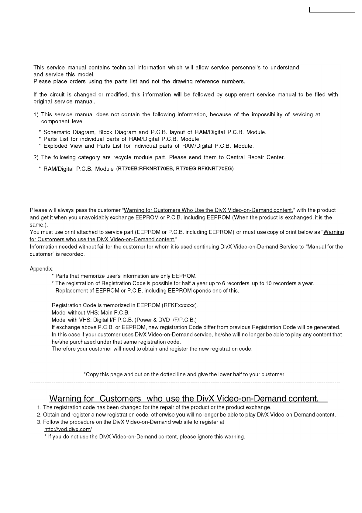
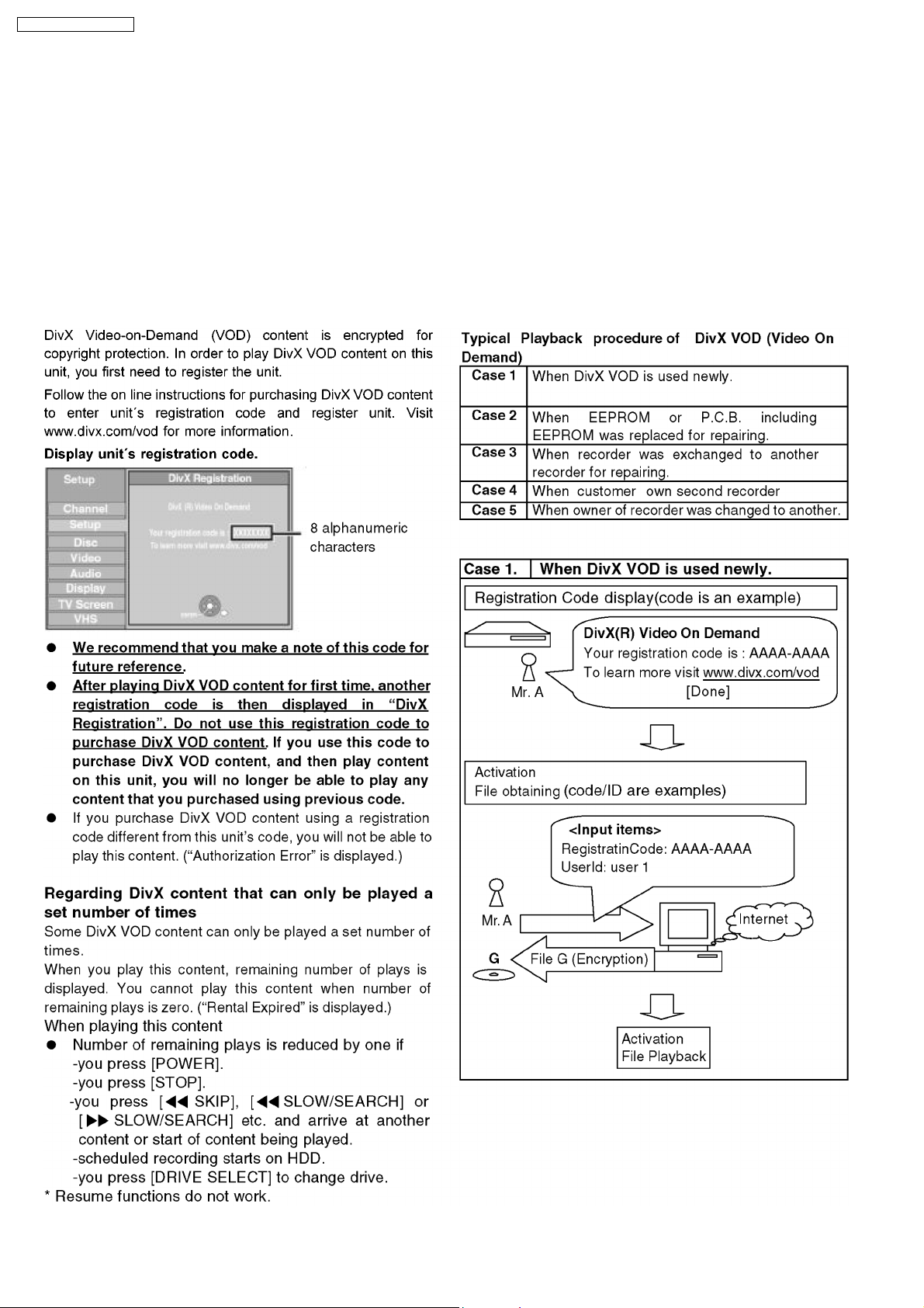
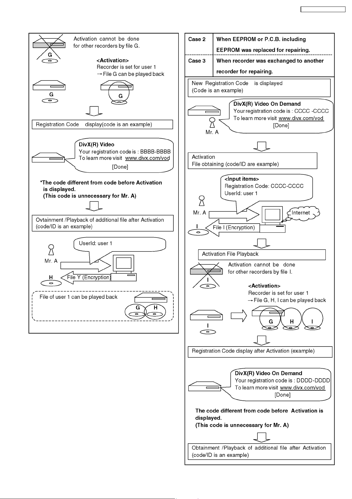
6.1.2. Operating Instructions about DivX Video-on-Demand Content
12
SA-RT70EB / SA-RT70EG
13
SA-RT70EB / SA-RT70EG
14
SA-RT70EB / SA-RT70EG
15
SA-RT70EB / SA-RT70EG
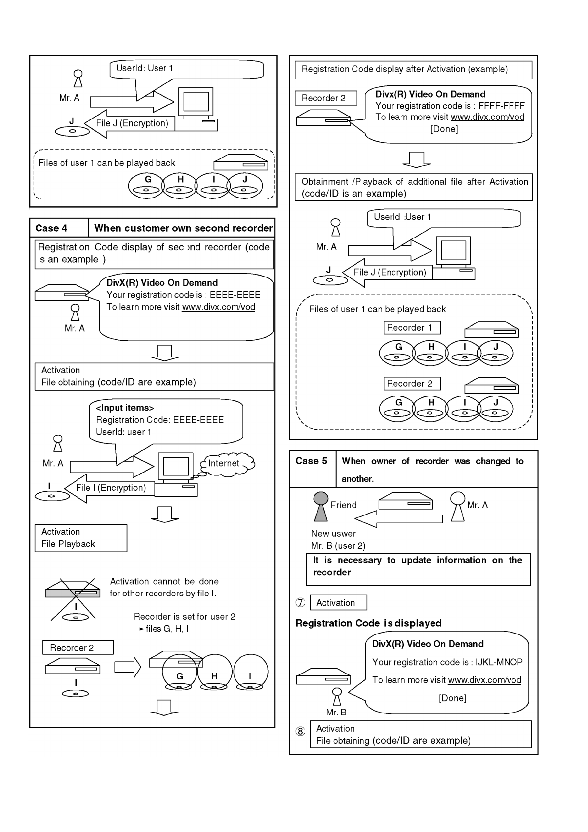
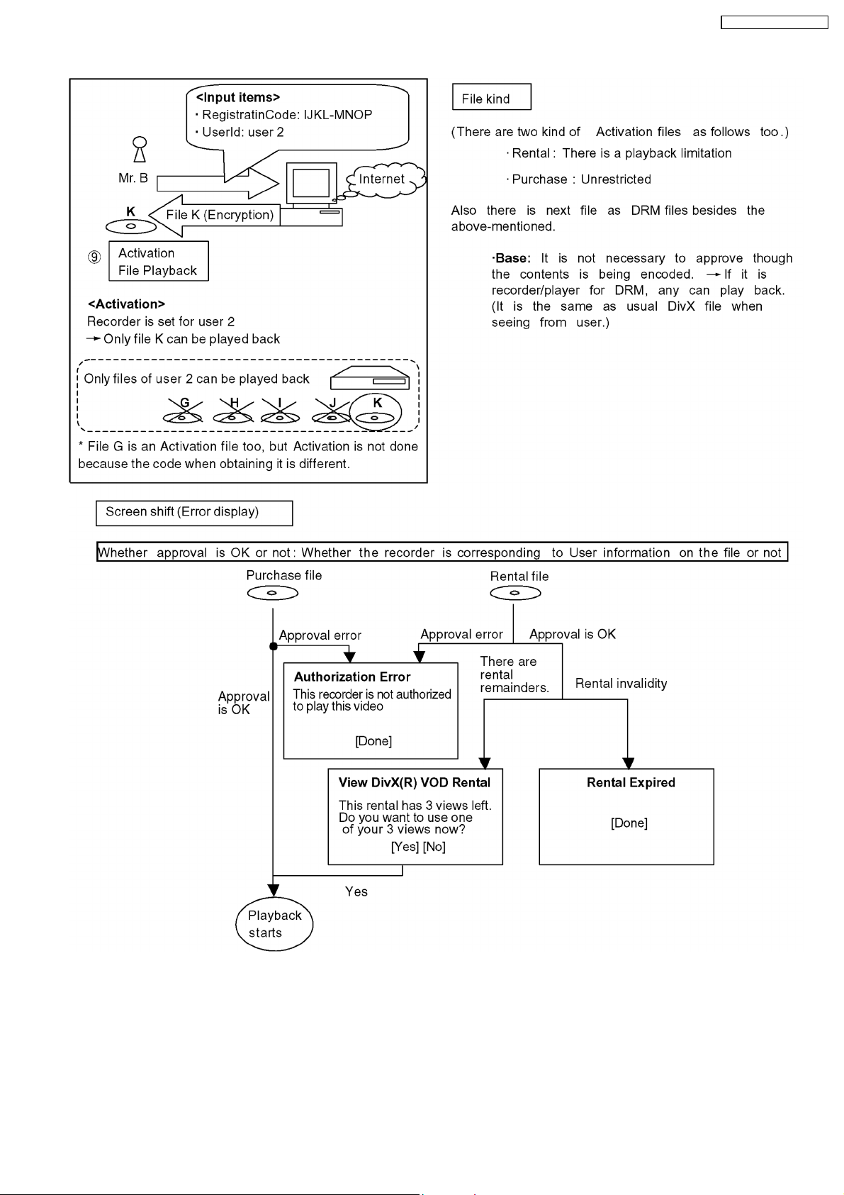
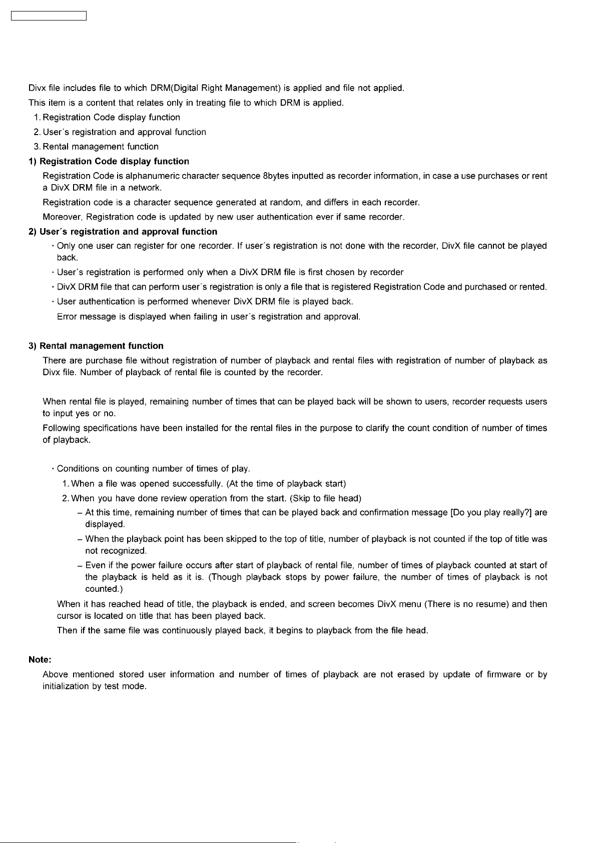
6.1.3. About DivX DRM
16
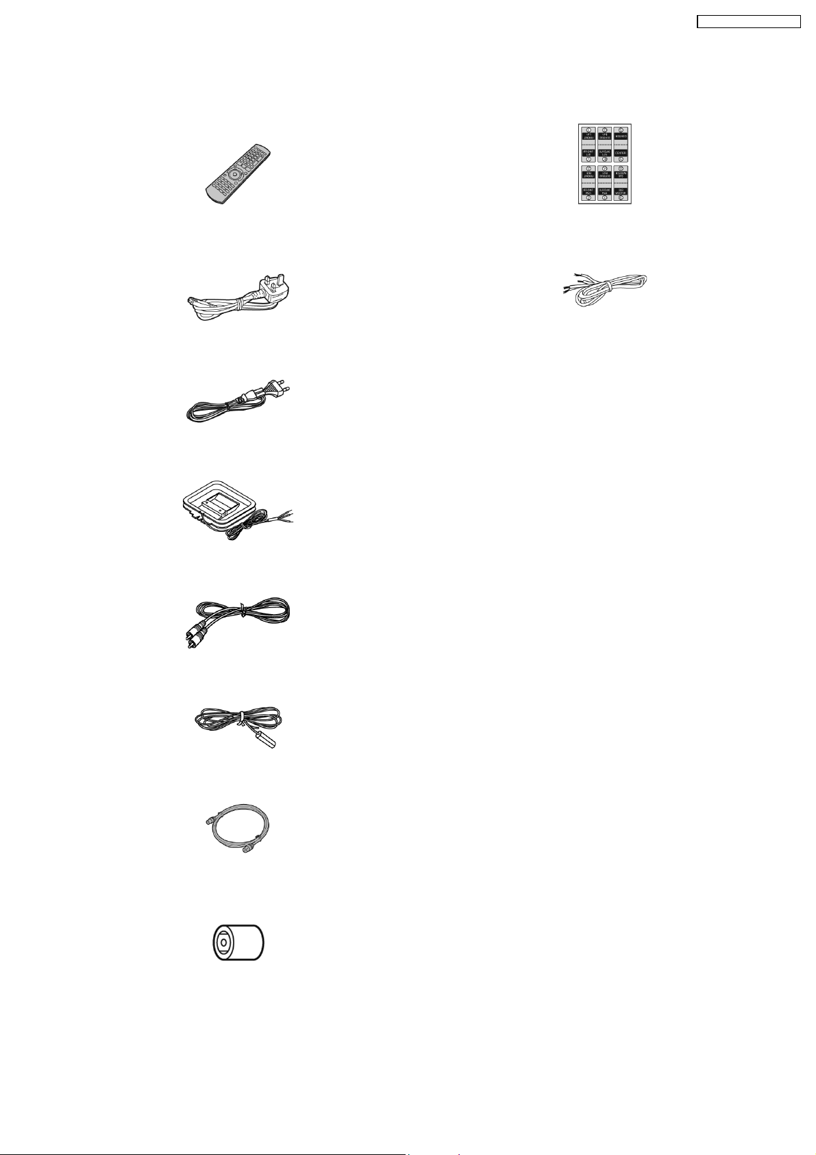
7 Accessories
Note : Refer to Packing Materials & Accessories (Section 24) for part number.
SA-RT70EB / SA-RT70EG
Remote
control
AC cord (EB)
AC cord (EG)
AM loop antenna
Speaker
label
Speaker cord
Video cable (EG)
FM antenna
RF coaxial
cable
Adaptor
(EB)
17
SA-RT70EB / SA-RT70EG
8 Operating Instructions Procedures
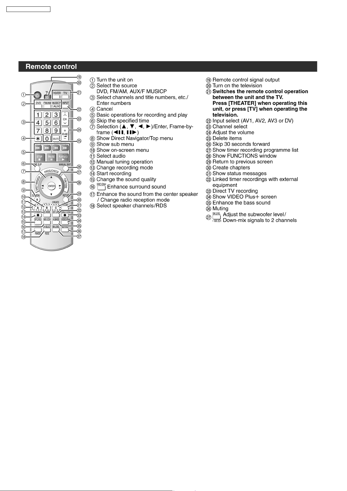
8.1. Remote Control Operation
18
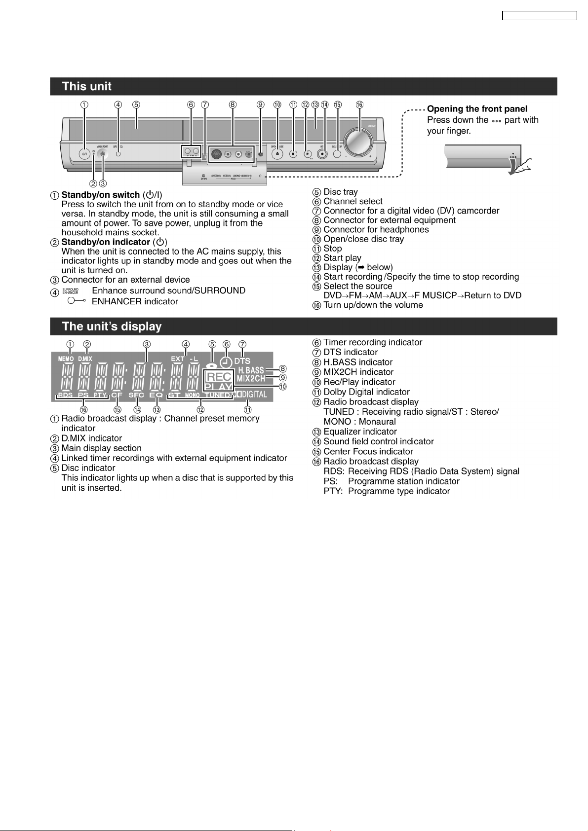
8.2. Main Unit Operation
SA-RT70EB / SA-RT70EG
19
SA-RT70EB / SA-RT70EG
8.3. Disc Information
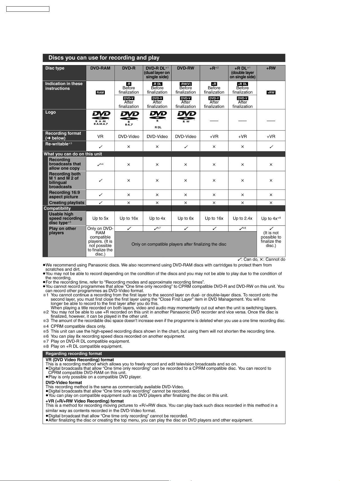
8.3.1. For Recording & Play
20
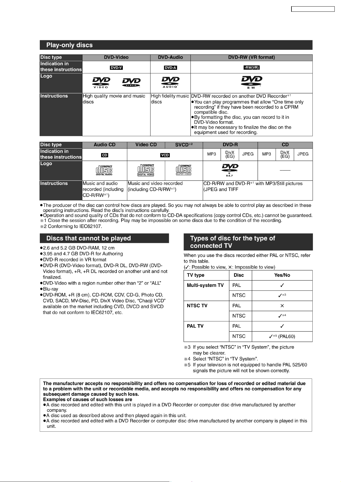
8.3.2. For Play only
SA-RT70EB / SA-RT70EG
21
SA-RT70EB / SA-RT70EG
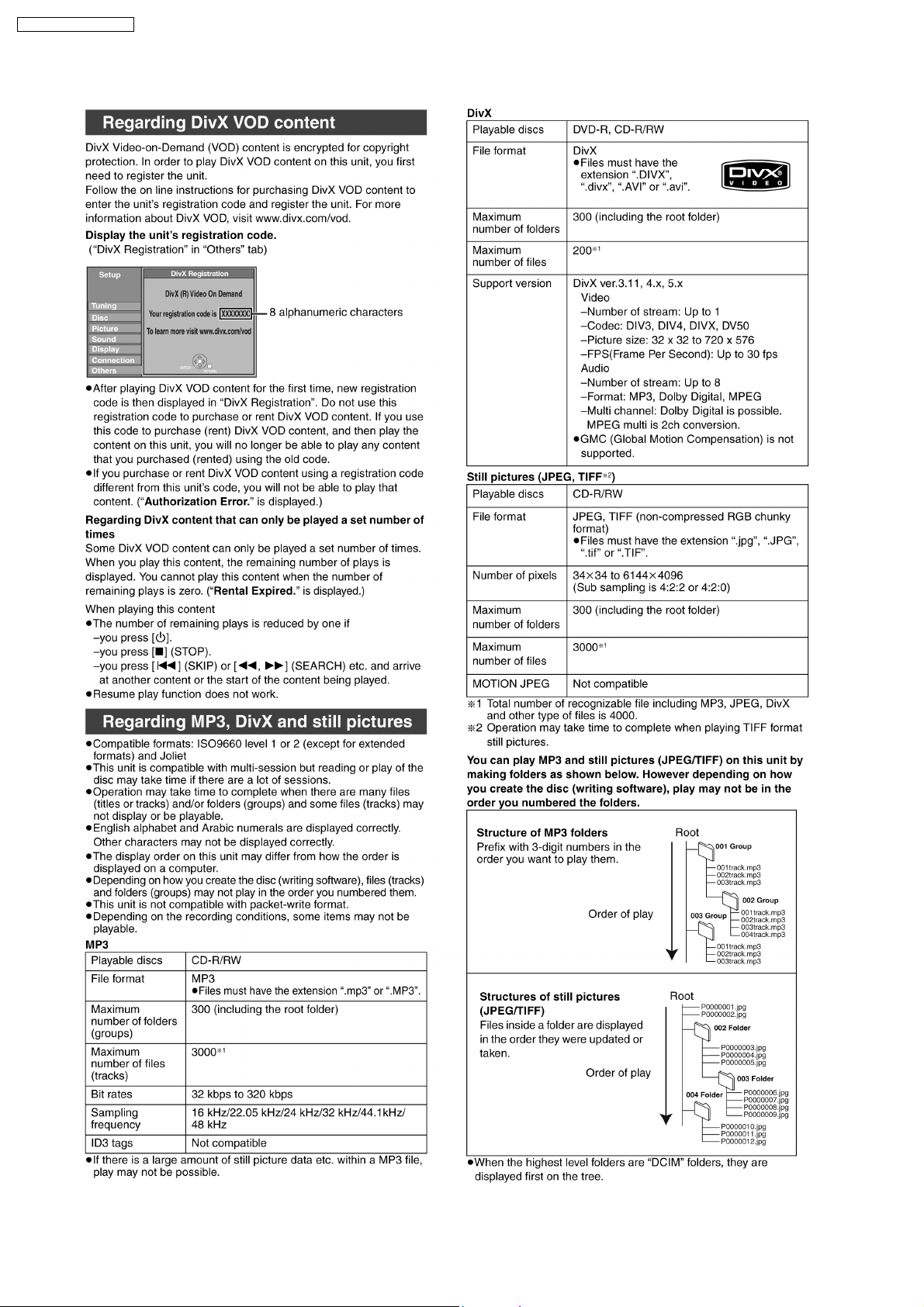
8.3.3. To play MP3, DivX and still pictures (JPEG/TIFF)
22
8.4. Video connections
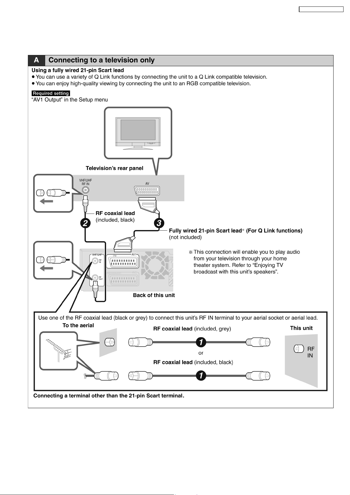
8.4.1. Connecting to a television only
SA-RT70EB / SA-RT70EG
23
SA-RT70EB / SA-RT70EG
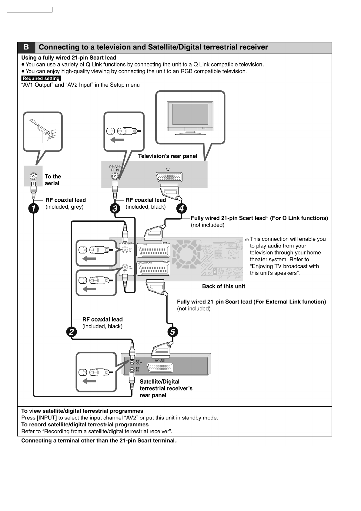
8.4.2. Connection to a television and Satellite/Digital terrestrial receiver
24
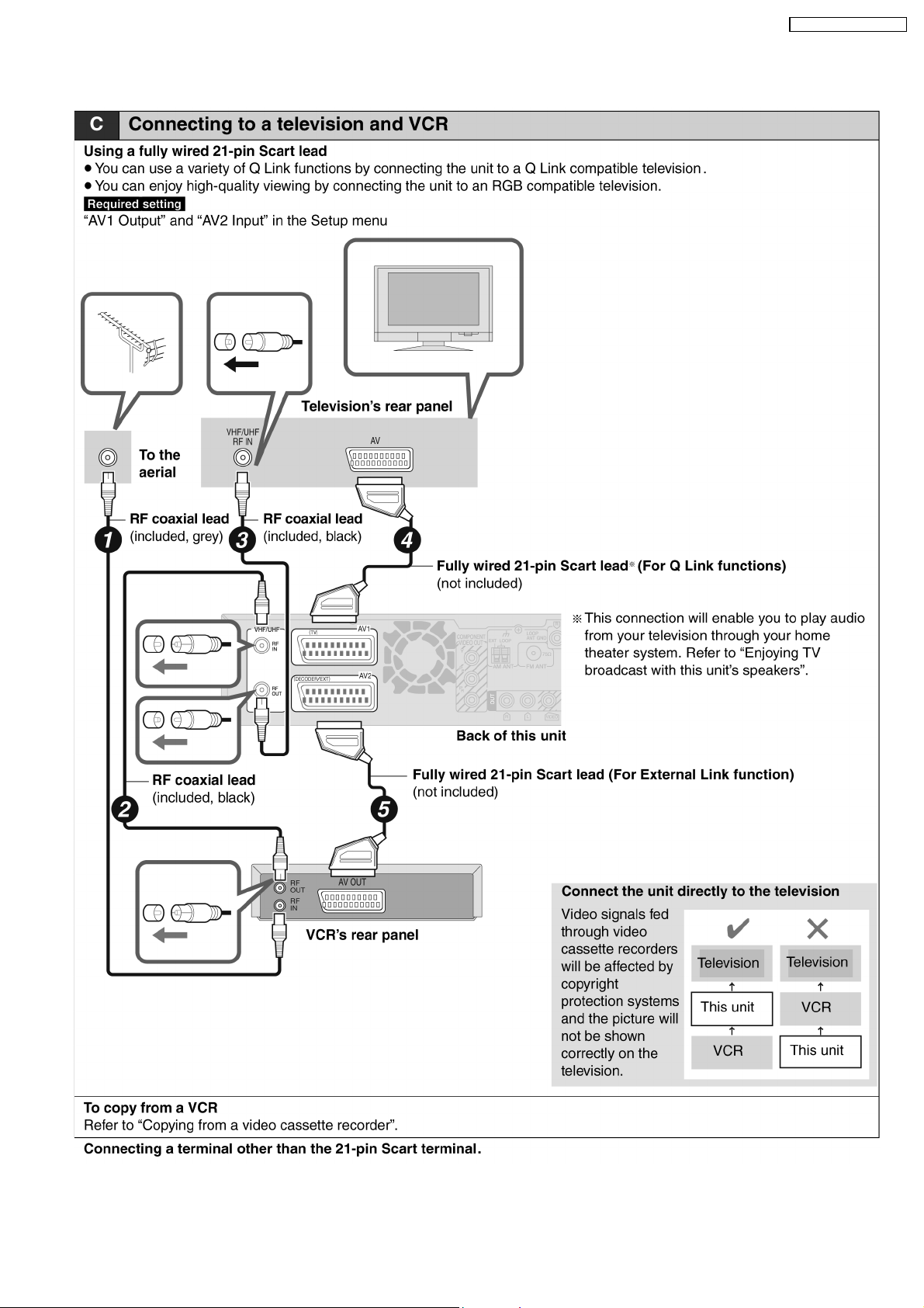
8.4.3. Connection to a television and VCR
SA-RT70EB / SA-RT70EG
25
SA-RT70EB / SA-RT70EG
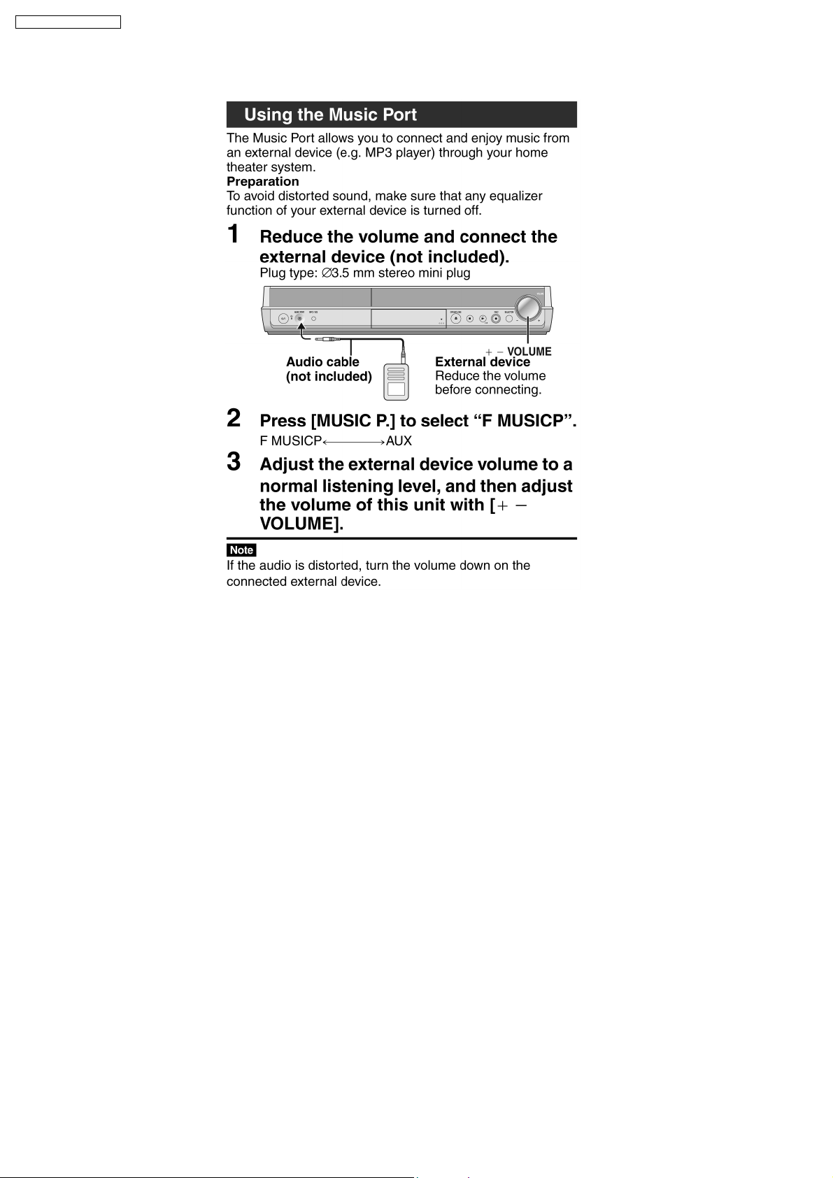
8.5. Use of Music Port
26
SA-RT70EB / SA-RT70EG
9 Operation Instructions
9.1. (DVD) Taking out the Disc from RAM-Drive Unit when the Disc cannot
be ejected by OPEN/CLOSE button
9.1.1. (DVD) Forcible Disc Eject
9.1.1.1. (DVD) When the power can be turned off.
1. Turn off the power and press [STOP], [CH UP] keys on the front panel simultaneously for 5 seconds.
9.1.1.2. (DVD) When the power can not be turned off.
1. Press [POWER] key on the front panel for over 10 seconds to turn off the power forcibly, and press [STOP] [CH UP] keys on
the front panel simultaneously for 5 seconds.
9.1.2. (DVD) When the Forcible Disc Eject can not be done.
1. Turn off the power and pull out AC cord.
2. Remove the Top Cabinet.
3. Remove Front Panel, but front FFCs need not be removed.
4. Remove 3 Screws fixing RAM Drive.
5. Do not damage 4 drive FFCs and raise RAM Drive.
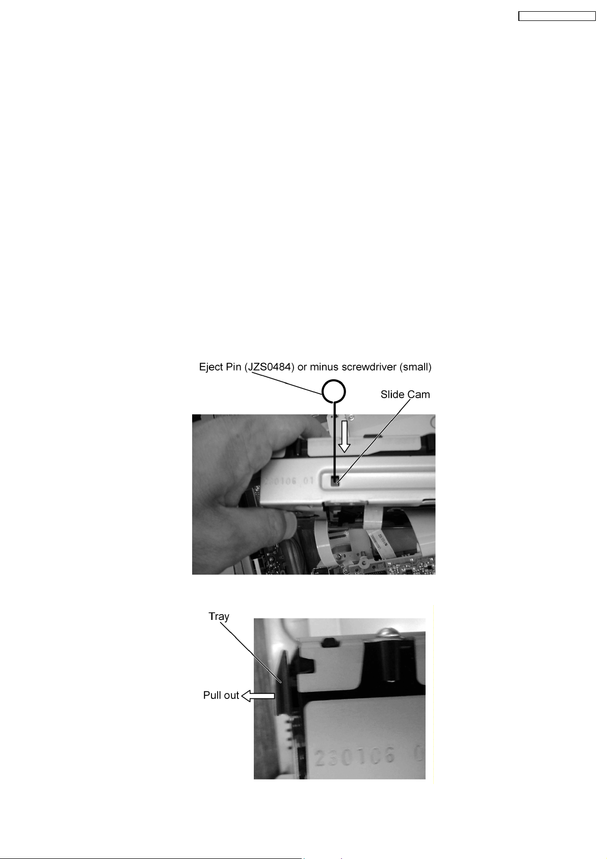
6. Hold RAM Drive and push in SLIDE CAM by Eject Pin (JZS0484) or minus screwdriver (small) to eject tray slightly.
7. Pull out Tray by hand.
27
SA-RT70EB / SA-RT70EG
10 Service Mode
10.1. (DVD) Self-Diagnosis and Special Mode Setting
10.1.1. (DVD) Self-Diagnosis Functions
Self-Diagnosis Function provides information for errors to service personnel by “Self-Diagnosis Display” when any error has
occurred.
U**, H** and F** are stored in memory and held.
You can check latest error code by transmitting [0] [1] of Remote Controller in Service Mode.
Automatic Display on FL will be cancelled when the power is turned off or AC input is turned off during self-diagnosis display is ON.
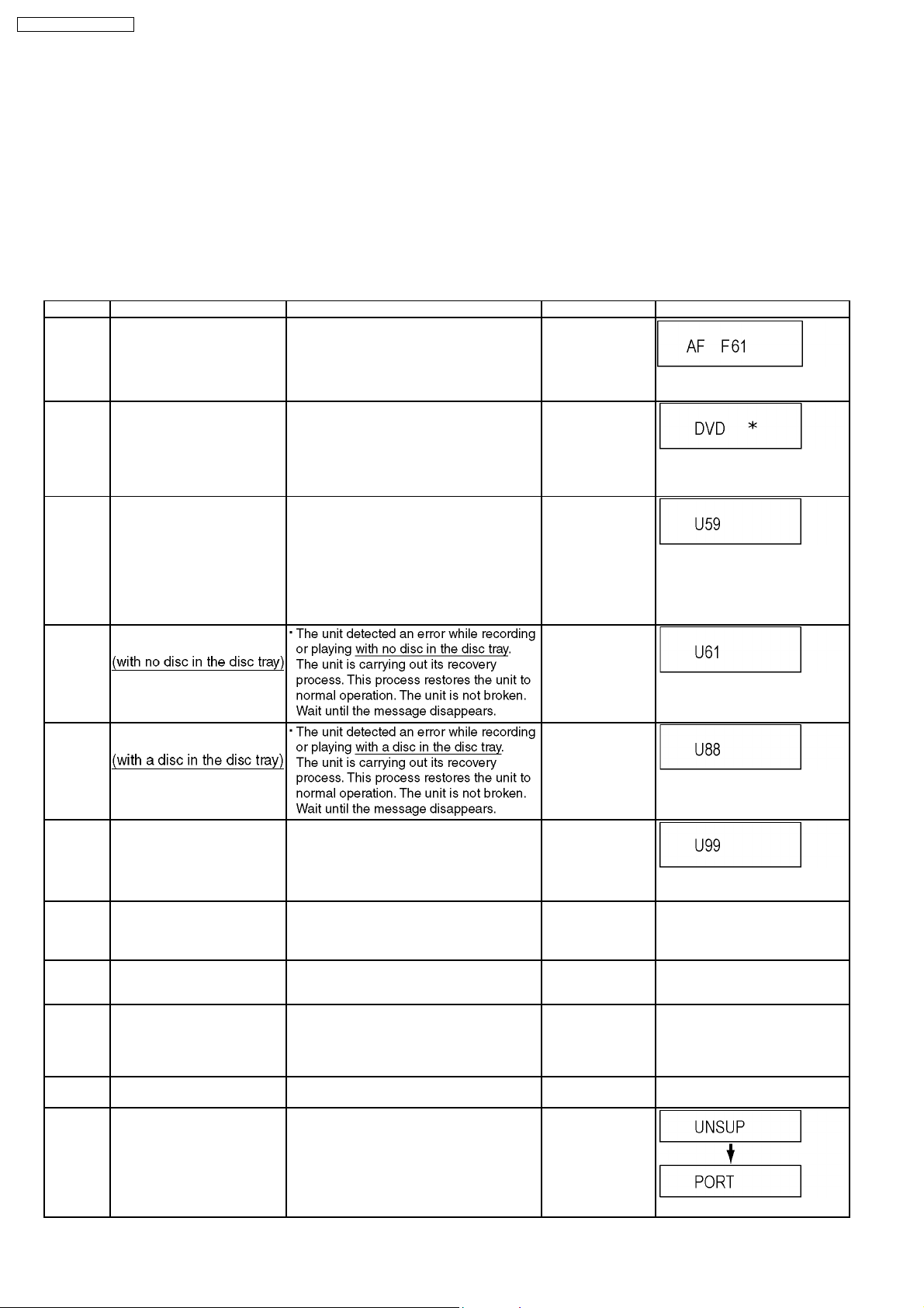
Error Code Diagnosis contents Description Monitor Display Automatic FL display
F61 Output malfunction of Power
Amp or Power Circuit
malfunction
U30 Remote control code error Display appears when main unit and remote
U59 Abnormal inner temperature
detected
U61 The unit is carrying out its
recovery process.
When DCDET becomes L during normal
operations, PCNT is turned to L and "AF F61"
is displayed.
controller codes are not matched.
Display appears when the drive temperature
exceeds 70°C.
The power is turned off forcibly.
For 30 minutes after this, all key entries are
disabled. (Fan motor operates at the highest
speed for the first 5 minutes. For the
remaining 25 minutes, fan motor is also
stopped.) The event is saved in memory as
well.
No display
"AF" was added for distinction
from DVD side.
No display
“*” is remote controller code of the
main unit.
Display for 5 seconds.
No display
“U59 is displayed for 30 minutes.
No display
U88 The unit is carrying out its
U99 Hang-up Displayed when communication error has
H19 Inoperative fan motor When inoperative fan motor is detected after
F00 No error information Initial setting for error code in memory
F34 Initialization error when main
F58 Drive hardware error When drive unit error is detected, the event is
UNSUPPORT
recovery process.
occurred between Main microprocessor and
Timer microprocessor.
powered on, the power is turned off
automatically.
The event is saved in memory.
(Error code Initialization is possible with error
code initialization and main unit initialization.)
microprocessor is started up
for program recording
Unsupported disc error *An unsupported format disc was played,
When initialization error is detected after
starting up main microprocessor for program
recording, the power is turned off
automatically.
The event is saved in memory.
saved in memory.
although the drive starts normally.
*The data format is not supported, although
the media type is supported.
*Exceptionally in case of the disc is dirty.
No display
No display
Displayed is left until the
[POWER] key is pressed.
No display No display
No display No display
No display No display
No display No display
“This disc is
incompatible.”
28
Display for 5 seconds.
SA-RT70EB / SA-RT70EG
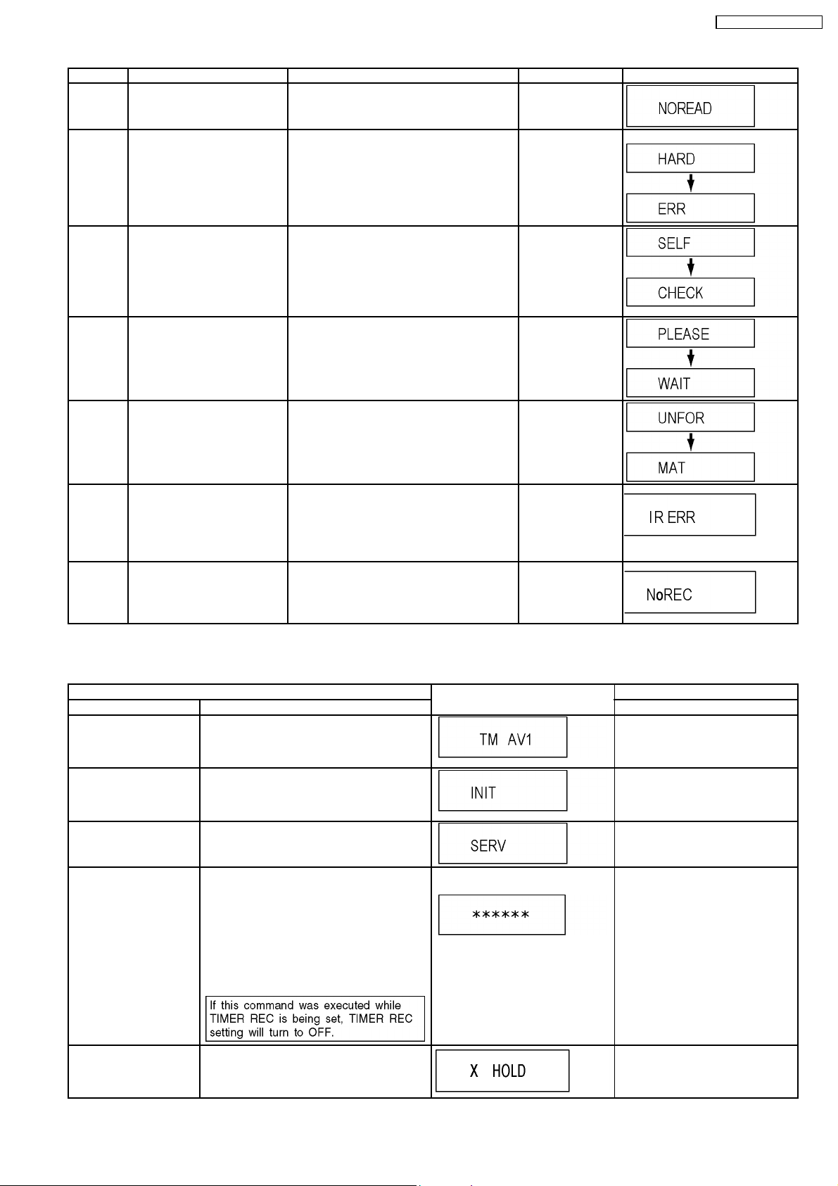
Error Code Diagnosis contents Description Monitor Display Automatic FL display
NO READ Disc read error *A disc is flawed or dirty.
HARD
ERR
Drive error The drive detected a hard error. “DVD drive error.” Display for 5 seconds.
*A poor quality failed to start.
*The track information could not be read.
“Cannot read.
Please check the
disc.”
SELF
CHECK
PLEASE
WAIT
UNFORMAT
IR ERR IR communication error [IR ERR] is displayed when communication
No REC Recording is impossible [No REC] is displayed when recording is
Restoration operation Since the power cord fell out during a power
failure or operation, it is under restoration
operation.
*It will OK, if a display disappears
automatically. If a display does not disappear,
there is the possibility that defective Digital
P.C.B. / RAM drive.
Unit is in termination process Unit is in termination process now.
“BYE” is displayed and power will be turned
off.
In case “Quick Start” of setup menu is ON, it
is displayed in restoration operation for AC
off.
Unformatted disc error You have inserted an unformatted DVD-RAM
or DVD-RW that is unformatted or recorded
on other equipment.
between Timer microprocessor and IR
microprocessor fails.
impossible due to the defect, dirt or wound of
media.
No display
No display
No display
Display for 5 seconds.
No display
10.1.2. (DVD) Special Modes Setting
Item FL display Key operation
Mode name Description Front Key
TEST Mode *All the main unit´s parameters (include tuner)
Rating password The audiovisual level setting password is
Service Mode Setting every kind of modes for servicing.
Forced disc eject Removing a disc that cannot be ejected. The
Child lock/unlock Set or release “Child Lock”. Press [ENTER] and [RETURN]
are initialized.
initialized to “Level 8”.
*Details are described in “10.1.3. (DVD)
Service Modes at a glance”.
tray will open and unit will shift to P-off mode.
*When Timer REC is ON or EXT-LINK is ON,
execute " Forced disc eject " after releasing
Timer REC or EXT-LINK.
*This command is not effective during "Child
lock" is ON. While Demonstration Lock is
being set, this Forced disc eject function is
not accepted.
The display before execution
leaves.
Press [CH UP], [STOP] and
[OPEN/CLOSE] keys
simultaneously for five seconds
when power is off.
Set DRIVE SELECT to [DVD].
While the tray is open, press [REC]
and [PLAY] simultaneously for 5
seconds.
When the power is off, press [REC]
+ [OPEN/CLOSE] and [CH UP]
keys simultaneously for 5 seconds.
When the power is off, press
[STOP] and [CH UP] keys
simultaneously for 5 seconds.
byremote controller
simultaneouslyuntil [X-HOLD] is
displayed.
29
SA-RT70EB / SA-RT70EG
Item FL display Key operation
Mode name Description Front Key
NTSC/PAL system select To switch PAL/NTSC altemately. The display before execution
leaves.
While the power is on (E-E mode),
press [STOP] and [OPEN/CLOSE]
simultaneously for 5 seconds.
Forced power-off When the power button is not effective while
power is ON, turn off the power forcibly.
*When Timer REC is ON, execute “Forced
Power-off” after releasing Timer REC.
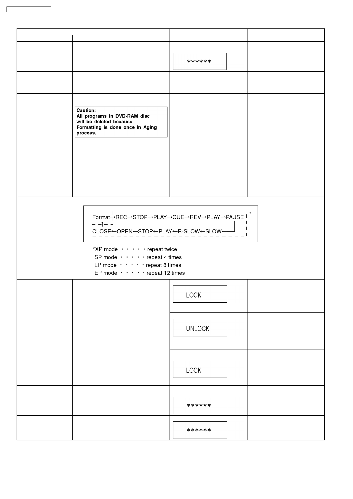
Aging Perform sequence of modes as * Aging
Description shown below continually.
Aging Contents (Example):
Display in P-off mode. Press [POWER] key over than 10
seconds.
Display following the then mode. When the power is ON, press [CH
DOWN], [REC] and [OPEN/CLOSE]
simultaneously for over 5 seconds
and less than 10 seconds.
NOTE1:
If Unit has not turned into Aging
mode by operations shown above,
execute TEST MODE once and reexecute operation shown above.
(*All the main unit’s parameters
include tuner are initialized by TEST
mode.)
NOTE2:
If the unit has hung-up because of
pressing keys for over 10 seconds,
once turn off the power, and reexecute this command.
*When releasing Aging mode, press
[POWER] key.
Demonstration
lock/unlock
Progressive initialization The progressive setting is initialized to
ATP re-execution Re-execute ATP. Display at ATP executing. When the power is on (E-E mode),
Ejection of the disc is prohibited.
The lock setting is effective until unlocking the
tray and not released by “Main unit
initialization” of service mode.
Interlace.
*When lock the tray.
“LOCK” is displayed for 3 seconds.
*When unlock the tray.
“UNLOCK” is displayed for 3
seconds.
*When press OPEN/CLOSE key
while the tray being locked.
Display “LOCK” for 3 seconds.
The display before execution
leaves.
When the power is on, press
[STOP] and [POWER] keys
simultaneously for 5 seconds.
Note:
When a disc is not in tray, this
setting is not effective.
When the power is on, press
[STOP] and [POWER] keys
simultaneously for 5 seconds.
Press [OPEN/CLOSE] key while the
tray being locked.
When the power is on (E-E mode),
press [STOP] and [PLAY]
simultaneously for 5 seconds.
press [CH UP] and [CH DOWN]
simultaneously for 5 seconds.
30
 Loading...