

Panasonic SAPT-860 Service manual
ORDER NO. MD0801011CE
DVD Home Theater Sound System
SA-PT860E
SA-PT860EB
SA-PT860EG
Colour
(K).......................Black Type
Notes: This model’s CD/DVD mechanism is DLS6. Please refer to the original service manual (Order No.
MD0801003CE) for this mechanism.
Specifications
Main unit SA-PT860E/EB/EG
O
OGENERAL
OO
Power supply: AC 230-240 V, 50 Hz
Power consumption: This unit 135 W
Power consumption in standby mode:
approx. 0.4 W
Dimensions (W×H×D): 430 mm×63 mm×327 mm
Mass: This unit 3.4 kg
Operating temperature range: 0°Cto+40°C
Operating humidity range: 35 % to 80 % RH
(no condensation)
O
OAMPLIFIER SECTION
OO
RMS Output Power: Dolby Digital Mode
Front Ch:
125 W per channel (3 Ω), 1 kHz, 10% THD
Surround Ch:
125 W per channel (3 Ω), 1 kHz, 10% THD
Center Ch:
250 W per channel (6 Ω), 1 kHz, 10% THD
Subwoofer Ch:
250 W per channel (6 Ω), 100 Hz, 10 % THD
Total RMS Dolby Digital mode power:
DIN Output Power: Dolby Digital Mode
Front Ch:
75 W per channel (3 Ω), 1 kHz, 1% THD
Surround Ch:
75 W per channel (3 Ω), 1 kHz, 1% THD
Center Ch:
145 W per channel (6 Ω), 1 kHz, 1% THD
Subwoofer Ch:
145 W per channel (6 Ω), 100 Hz, 1 % THD
Total DIN Dolby Digital mode power:
O
OFM TUNER, TERMINALS SECTION
OO
Preset Memory: FM 30 stations
Frequency Modulation (FM)
1000 W
590 W
© 2008 Matsushita Electric Industrial Co. Ltd.. All
rights reserved. Unauthorized copying and
distribution is a violation of law.

SA-PT860E / SA-PT860EB / SA-PT860EG
Frequency range:
87.50-108.00 MHz (50-kHz step)
Antenna terminals: 75 Ω (unbalanced)
Digital audio input
Optical digital input: Optical terminal
Sampling frequency: 32 kHz, 44.1 kHz, 48 kHz
Phone jack
Terminal: Stereo, 3.5 mm jack
USB Port
USB standard: USB 2.0 full speed
Media file format support: MP3 (*.mp3)
WMA (*.wma)
JPEG (*.jpg) (*.jpeg)
MPEG4 (*.asf) (For E/EG only)
USB device file system: FAT12, FAT16, FAT32
USB Port power: Max. 500 mA
O
ODISC SECTION (EB area)
OO
Discs played [8 cm or 12 cm]:
(1) DVD (DVD-Video)
(2) DVD-RAM (DVD-VR, MP3
*2, 5
(3) DVD-R (DVD-Video, DVD-VR, MP3
, JPEG
*4, 5
*2, 5
)
, JPEG
*4, 5
)
(4) DVD-R DL (DVD-Video, DVD-VR)
(5) DVD-RW (DVD-Video, DVD-VR, MP3
*2, 5
, JPEG
*4, 5
)
(6) +R/+RW (Video)
(7) +R DL (Video)
(8) CD, CD-R/RW [CD-DA, Video CD, SVCD*1,MP3
*1
*2
*3
*4, 5
5
, JPEG
]
Conforming to IEC62107
MPEG-1 Layer 3, MPEG-2 Layer 3
Windows Media Audio Ver.9.0 L3
*2, 5
ONot compatible with Multiple Bit Rate (MBR)
*4
Exif Ver 2.1 JPEG Baseline files
OPicture resolution: between 160 x 120 and 6144 x 4096
pixels (Sub sampling is 4:0:0, 4:2:0, 4:2:2 or 4:4:4).
Extremely long and narrow pictures may not be displayed.
*5
The total combined maximum number of recognizable audio
and picture contents and groups: 4000 audio and picture
contents and 400 groups.
O
ODISC SECTION (E/EG areas)
OO
Discs played [8 cm or 12 cm]:
(1) DVD (DVD-Video, DivX
(2) DVD-RAM (DVD-VR, MP3
*5, 6
)
*2, 5
, JPEG
*4, 5
, MPEG4
*5, 7
)
(3) DVD-R (DVD-Video, DVD-VR, MP3
7
, DivX
*5, 6
)
*2, 5
, JPEG
*4, 5
, MPEG4
(4) DVD-R DL (DVD-Video, DVD-VR)
(5) DVD-RW (DVD-Video, DVD-VR, MP3
MPEG4
*5, 7
, DivX
*5, 6
)
*2, 5
, JPEG
*4, 5
,
(6) +R/+RW (Video)
(7) +R DL (Video)
(8) CD, CD-R/RW [CD-DA, Video CD, SVCD*1,MP3
*1
*2
*3
5
, JPEG
*4, 5
, MPEG4
*5, 7
, DivX
*5, 6
]
Conforming to IEC62107
MPEG-1 Layer 3, MPEG-2 Layer 3
Windows Media Audio Ver.9.0 L3
*2, 5
ONot compatible with Multiple Bit Rate (MBR)
,WMA
, DivX
,WMA
*3,
*5, 6
*5,
*3,
*4
Exif Ver 2.1 JPEG Baseline files
OPicture resolution: between 160 x 120 and 6144 x 4096
pixels (Sub sampling is 4:0:0, 4:2:0, 4:2:2 or 4:4:4).
Extremely long and narrow pictures may not be displayed.
*5
The total combined maximum number of recognizable audio,
picture and video contents and groups: 4000 audio, picture
and video contents and 400 groups.
*6
Plays all versions of DivX® video (including DivX®6) with
standard playback of DivX® media files. Certified to the DivX
Home Theater Profile.
*7
MPEG4 data recorded with the Panasonic SD multi cameras
or DVD video recorders.
OConforming to SD VIDEO specifications (ASF standard)/
MPEG4 (Simple Profile) video system/G.726 audio system.
Pick up
Wavelength (DVD/CD): 655/785 nm
Laser power (DVD/CD): CLASS 1/CLASS 1M
Audio output (Disc)
Number of channels: 5.1ch(FL,FR,C,SL,SR,
SW)
O
OVIDEO SECTION
OO
Video system: PAL625/50, PAL525/60, NTSC
Composite video output
Output level: 1Vp-p(75Ω)
Terminal: Scart jack (1 system)
S-video output
Y output level: 1Vp-p(75Ω)
C output level: PAL; 0.3 Vp-p (75 Ω)
NTSC; 0.286 Vp-p (75 Ω)
Terminal: Scart jack (1 system)
Component Video Output
O
OY output level: 1Vp-p(75Ω)
OO
O
OPBoutput level: 0.7Vp-p(75Ω)
OO
O
OPRoutput level: 0.7Vp-p(75Ω)
OO
O
OTerminal: Pin jack (Y: green, PB:blue,
OO
P
:red)(1system)
R
RGB video output
R output level: 0.7Vp-p(75Ω)
G output level: 0.7Vp-p(75Ω)
B output level: 0.7Vp-p(75Ω)
Terminal: Scart jack (1 system)
HDMI AV output
Terminal: 19pin type A connector
HDAVI Control:
This unit supports “HDAVI Control 3” function.
Note:
1. Specifications are subject to change without notice.
Mass and dimensions are approximate.
2. Total harmonic distortion is measured by the digital spectrum
analyzer.
Solder:
This model uses lead free solder (PbF).
Mechanism:
This model uses DLS6 mechanism.
Wireless Features:
This model supports wireless surround (example SH-FX67).
2
Refer to their respective original service manuals for *1.
SA-PT860E / SA-PT860EB / SA-PT860EG
3
SA-PT860E / SA-PT860EB / SA-PT860EG
CONTENTS
Page Page
1 Safety Precautions 6
1.1. GENERAL GUIDELINES
1.2. Before Repair and Adjustment
1.3. Protection Circuitry
1.4. Safety Parts Information
1.5. Caution for AC Cord (For EB only)
2 Prevention of Electrostatic Discharge (ESD) to
Electrostatically Sensitive (ES) Devices
3 Precaution of Laser Diode
4 About Lead Free Solder (PbF)
4.1. Service caution based on legal restrictions
5 Handling Precautions for Traverse Unit
5.1. Cautions to Be Taken in Handling the Optical Pickup Unit
5.2. Grounding for electrostatic breakdown prevention
6 Accessories
7 Operation Procedures
7.1. Remote Control Key Buttons Operations
7.2. Main Unit Key Buttons Operations
7.3. Using the VIERA Link “HDAVI Control™”
7.4. Using the iPod
7.5. USB Connection and Operation
7.6. Audio and Video Connection
7.7. Disc Information
8 Self-Diagnosis and Special Mode Setting
8.1. Service Mode Summary Table
8.2. Service Mode Table
8.3. Wireless Service Mode Summary Table
8.4. Service Mode Table (Wireless - eg. SH-FX67)
8.5. DVD Self Diagnostic Function-Error Code
8.6. Sales Demonstration Lock Function
8.7. Service Precautions
9 Assembling and Disassembling
9.1. Disassembly Flow Chart
9.2. Main Components and P.C.B. Locations
9.3. Disassembly of Top Cabinet
9.4. Disassembly of Rear Panel
9.5. Disassembly of Scart P.C.B.
9.6. Disassembly of DVD Mechanism Unit
9.7. Disassembly of Front Panel
9.8. Disassembly of Panel P.C.B.
9.9. Disassembly of Power Button P.C.B.
9.10. Disassembly of USB/Setup Mic P.C.B.
10
11
11
12
12
12
14
15
15
16
17
19
21
22
24
26
26
26
33
34
36
38
39
41
43
44
45
45
45
46
46
47
47
47
6
6
6
7
8
9
9.11. Disassembly of DVD Lid
9.12. Disassembly of Ipod Cradle P.C.B.
9.13. Disassembly of AC Inlet P.C.B.
9.14. Disassembly of Main P.C.B.
9.15. Disassembly of D-Amp P.C.B.
9.16. Replacement of Digital Amp IC (IC5000)
9.17. Replacement of Digital Amp IC (IC5200)
9.18. Replacement of Digital Amp IC (IC5300)
9.19. Replacement of Digital Amp IC (IC5400)
9.20. Disassembly of SMPS P.C.B.
9.21. Replacement of Switch Regulator IC (IC5701)
9.22. Replacement of Switch Regulator Diode (D5702)
9.23. Replacement of Regulator Diode (D5801)
9.24. Replacement of Regulator Diode (D5802)
9.25. Replacement of Regulator Diode (D5803)
9.26. Disassembly of Power Supply P.C.B.
9.27. Replacement of Regulator IC (IC2903)
9.28. Disassembly of DVD Module P.C.B.
9.29. Disassembly of Coprocessor P.C.B.
9.30. Disassembly of Wireless Adapter P.C.B.
10 Assemb ling and Disassembling of DVD Mecha nism Uni t
10.1. Disassembly of traverse unit
10.2. Assembly of traverse unit
11 Service Fixture and Tools
12 Service Position
12.1. Checking & Repairing Main P.C.B.
12.2. Checking & Repairing D-Amp P.C.B.
12.3. Checking & Repairing SMPS P.C.B.
12.4. Checking & Repairing Power Supply P.C.B.
12.5. Checking & Repairing DVD Module P.C.B.
13 Measurements and Adjustments
13.1. Service Tools and Equipment
13.2. Important points in adjustment
13.3. Storing and handling of test discs
13.4. Optical adjustment
14 Vol tage an d Waveform Chart
14.1. DVD Module P.C.B.
14.2. D-Amp P.C.B.
14.3. Main P.C.B.
14.4. Panel P.C.B.
14.5. Power Supply P.C.B.
14.6. USB/Setup Mic AC Inlet P.C.B.
14.7. Scart P.C.B.
48
48
49
50
51
51
53
54
56
57
57
58
60
60
61
62
63
64
65
65
66
66
68
70
71
71
71
73
73
74
77
77
77
77
78
79
79
81
82
83
83
84
84
4

SA-PT860E / SA-PT860EB / SA-PT860EG
14.8. SMPS P.C.B. 84
14.9. Waveform Chart
15 Illustration of IC’s, Transistors and Diodes
16 Wiring Connection Diagram
17 Block Diagram
17.1. System Control
17.2. DVD (Servo)
17.3. DVD (Audio)
17.4. DVD (HDMI)
17.5. VIDEO
17.6. Audio
17.7. Digital Audio Amp
17.8. Power
18 Schem atic Diagram Notes
19 Schematic Diagram
19.1. DVD Module Circuit
19.2. Main Circuit
19.3. Panel, Power Button Circuit
19.4. USB/Setup Mic Circuit
19.5. D-Amp Circuit
19.6. Power Supply Circuit
19.7. SMPS Circuit
19.8. AC Inlet, Ipod Cradle
19.9. Coprocessor, Wireless Adapter Circuit
19.10. Scart Circuit
20 Prin ted Circui t Board
85
88
89
91
91
92
93
94
95
96
97
98
99
101
101
106
110
111
112
114
116
118
119
120
121
20.1. DVD Module P.C.B.
20.2. Main P.C.B.
20.3. Panel, Power Button, USB/Setup Mic, Power Supply & AC
Inlet P.C.B.
20.4. D-Amp P.C.B.
20.5. SMPS P.C.B.
20.6. Ipod Cradle, Scart, Coprocessor & Wireless Adapter
P.C.B.
21 Basic Troubleshooting Guide
21.1. Troubleshooting Guide for F61 and/or F76
21.2. Basic Troubleshooting Guide for Traverse Unit (DVD
Module P.C.B.)
21.3. Basic Troubleshooting Guide for HDMI AV Output
22 Overall Simplified Block for PT860
22.1. SMPS Module & Power Supply Block
23 Terminal Function of ICs
23.1. IC2001 (RFKWPT460E): IC System Control
23.2. IC1701 (MFI341S2095): IC Ipod Video
23.3. IC6901(C0HBB0000057): IC FL Driver
24 Expl od ed Views
24.1. Cabinet Parts Location
24.2. Packaging
25 Repl acement Parts List
25.1. Component Parts List
26 Schem atic Diagra m for printing with letter size
121
122
123
124
125
126
127
127
134
135
137
138
139
139
139
140
141
141
142
143
144
160
5
SA-PT860E / SA-PT860EB / SA-PT860EG
1 Safety Precautions
1.1. GENERAL GUIDELINES
1. When servicing, observe the original lead dress. If a short circuit is found, replace all parts which have been overheated or
damaged by the short circuit.
2. After servicing, see to it that all the protective devices such as insulation barriers, insulation papers shields are properly
installed.
3. After servicing, carry out the following leakage current checks to prevent the customer from being exposed to shock hazards.
1.1.1. LEAKAGE CURRENT COLD CHECK
1. Unplug the AC cord and connect a jumper between the two prongs on the plug.
2. Measure the resistance value, with an ohmmeter, between the jumpered AC plug and each exposed metallic cabinet part on
the equipment such as screwheads, connectors, control shafts, etc. When the exposed metallic part has a return path to the
chassis, the reading should be between 1MΩ and 5.2MΩ.
When the exposed metal does not have a return path to the chassis, the reading must be
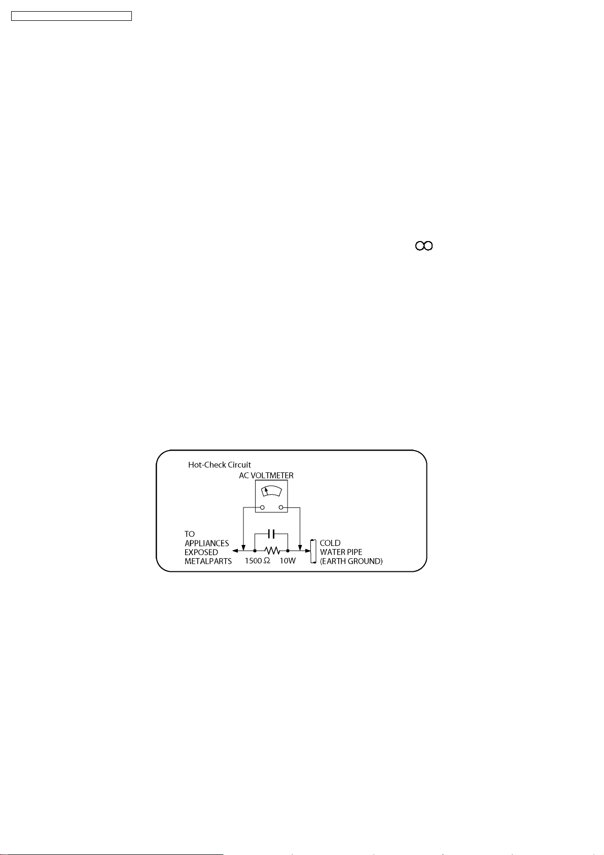
1.1.2. LEAKAGE CURRENT HOT CHECK
1. Plug the AC cord directly into the AC outlet. Do not use an isolation transformer for this check.
2. Connect a 1.5kΩ, 10 watts resistor, in parallel with a 0.15µF capacitors, between each exposed metallic part on the set and a
good earth ground such as a water pipe, as shown in Figure 1.
3. Use an AC voltmeter, with 1000 ohms/volt or more sensitivity, to measure the potential across the resistor.
4. Check each exposed metallic part, and measure the voltage at each point.
5. Reverse the AC plug in the AC outlet and repeat each of the above measurements.
6. The potential at any point should not exceed 0.75 volts RMS. A leakage current tester (Simpson Model 229 or equivalent) may
be used to make the hot checks, leakage current must not exceed 1/2 milliamp. In case a measurement is outside of the limits
specified, there is a possibility of a shock hazard, and the equipment should be repaired and rechecked before it is returned to
the customer.
Figure 1
1.2. Before Repair and Adjustment
Disconnect AC power to discharge unit AC Capacitors as such C5700, C5701, C5703, C5704, C5705, C5706, C5707 through a
10 Ω, 10 W resistor to ground.
Caution:
DO NOT SHORT-CIRCUIT DIRECTLY (with a screwdriver blade, for instance), as this may destroy solid state devices.
After repairs are completed, restore power gradually using a variac, to avoid overcurrent.
Current consumption at AC 230 V~240 V, 50 Hz in NO SIGNAL mode volume minimal should be ~ 600 mA. (EB)
Current consumption at AC 230 V, 50 Hz in NO SIGNAL mode volume minimal should be ~ 600 mA. (E/EG)
1.3. Protection Circuitry
The protection circuitry may have operated if either of the following conditions are noticed:
•
• No sound is heard when the power is turned on.
• •
•
• Sound stops during a performance.
• •
6
SA-PT860E / SA-PT860EB / SA-PT860EG
The function of this circuitry is to prevent circuitry damage if, for example, the positive and negative speaker connection wires are
“shorted”, or if speaker systems with an impedance less than the indicated rated impedance of the amplifier are used.
If this occurs, follow the procedure outlines below:
1. Turn off the power.
2. Determine the cause of the problem and correct it.
3. Turn on the power once again after one minute.
Note:
When the protection circuitry functions, the unit will not operate unless the power is first turned off and then on again.
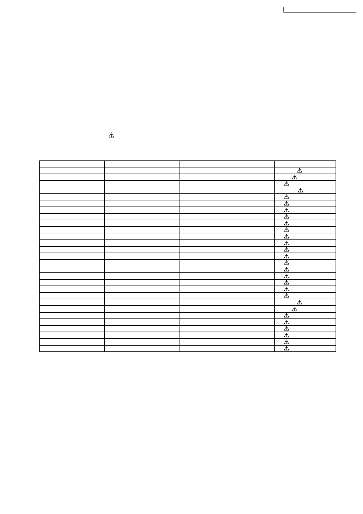
1.4. Safety Parts Information
Safety Parts List:
There are special components used in this equipment which are important for safety.
These parts are marked by
should be replaced with manufacturer’s specified parts to prevent shock, fire or other hazards. Do not modify the original design
without permission of manufacturer.
Ref. No. Part No. Part Name & Description Remarks
23 RGRX0067B-C REAR PANEL [M] E/EG
23 RGRX0067B-D REAR PANEL [M] EB
66 RKMX0141-K TOP CABINET [M]
PCB3 REPX0622B SMPS / AC INLET P.C.B [M] (RTL)
DZ5701 ERZV10V511CS ZENER [M]
L5701 ELF15N035AN LINE FILTER [M]
L5702 G0B932H00001 LINE FILTER [M]
L5703 ELF22V020A LINE FILTER [M]
T2900 G4D1A0000117 SWITCHING TRAN SFORMER [M]
T5701 ETS42BN1A6AD SWITCHING TRANSFORMER [M]
T5751 ETS19AB256AG SWITCHING TRANSFORMER [M]
PC5701 B3PBA0000402 PHOTO COUPLER [M]
PC5702 B3PBA0000402 PHOTO COUPLER [M]
PC5720 B3PBA0000402 PHOTO COUPLER [M]
PC5799 B3PBA0000402 PHOTO COUPLER [M]
F1 K5D502BNA005 FUSE [M]
FP2901 K5G401A00008 FUSE PROTECTOR [M]
TH5701 D4CAC8R00002 THERMISTOR [M]
TH5860 D4CC11040013 THERMISTOR [M]
P5701 K2AA2B000017 AC INLET [M]
A2 K2CQ2CA00007 AC CORD [M] E/EG
A2 K2CT3CA00004 AC CORD [M] EB
C5700 F1BAF1020020 1000pF [M]
C5701 F0CAF334A087 0.33uF [M]
C5704 F1BAF1020020 1000pF [M]
C5705 F1BAF1020020 1000pF [M]
C5706 F1BAF1020020 1000pF [M]
C5707 F1BAF1020020 1000pF [M]
in the Schematic Diagrams & Replacement Parts List. It is essential that these critical parts
Table 1
7
SA-PT860E / SA-PT860EB / SA-PT860EG
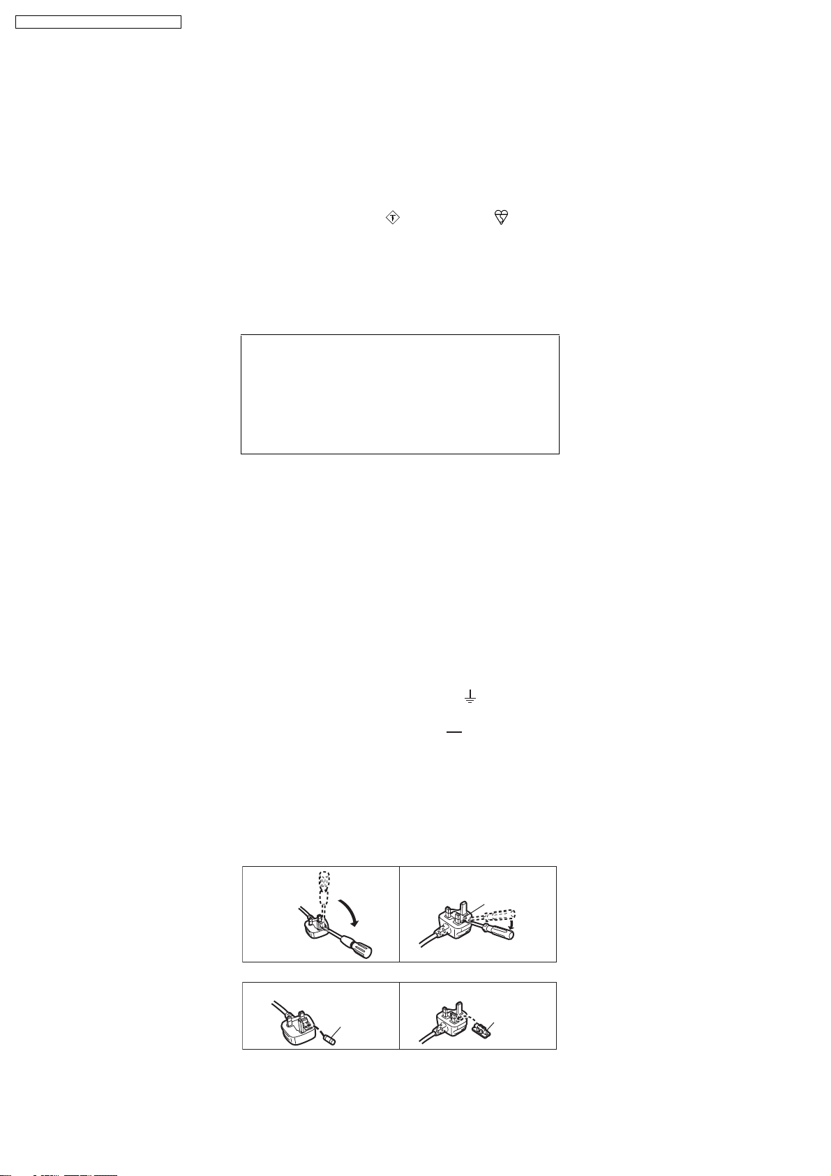
1.5. Caution for AC Cord (For EB only)
For your safety, please read the following text carefully.
This appliance is supplied with a moulded three pin
mains plug for your safety and convenience.
A 5-ampere fuse is fitted in this plug.
Should the fuse need to be replaced please ensure that
the replacement fuse has a rating of 5-ampere and that it
is approved by ASTA or BSI to BS1362.
Check for the ASTA mark or the BSI mark on the
body of the fuse.
If the plug contains a removable fuse cover you must
ensure that it is refitted when the fuse is replaced.
If you lose the fuse cover the plug must not be used until
a replacement cover is obtained.
A replacement fuse cover can be purchased from your
local dealer.
CAUTION!
IF THE FITTED MOULDED PLUG IS UNSUITABLE
FOR THE SOCKET OUTLET IN YOUR HOME THEN
THE FUSE SHOULD BE REMOVED AND THE PLUG
CUT OFF AND DISPOSED OF SAFELY.
THERE IS A DANGER OF SEVERE ELECTRICAL
SHOCK IF THE CUT OFF PLUG IS INSERTED INTO
ANY 13-AMPERE SOCKET.
If a new plug is to be fitted please observe the wiring
code as stated below.
If in any doubt please consult a qualified electrician.
IMPORTANT
The wires in this mains lead are coloured in accordance
with the following code:
Blue: Neutral, Brown: Live.
As these colours may not correspond with the coloured
markings identifying the terminals in your plug, proceed
as follows:
The wire which is coloured Blue must be connected to the terminal
which is marked with the letter N or coloured Black or Blue.
The wire which is coloured Brown must be connected to the
terminal which is marked with the letter L or coloured Brown or Red.
WARNING: DO NOT CONNECT EITHER WIRE TO THE
EARTH TERMINAL WHICH IS MARKED WITH THE
LETTER E, BY THE EARTH SYMBOL OR
COLOURED GREEN OR GREEN/YELLOW.
THIS PLUG IS NOT WATERPROOF KEEP DRY.
Before use
Remove the connector cover.
How to replace the fuse
The location of the fuse differ according to the type of AC
mains plug (figures A and B). Confirm the AC mains plug
fitted and follow the instructions below.
Illustrations may differ from actual AC mains plug.
1. Open the fuse cover with a screwdriver.
Figure A Figure B
A A
Fuse cover
2. Replace the fuse and close or attach the fuse cover.
Figure A Figure B
Fuse
(5 ampere)
8
Fuse
(5 ampere)

SA-PT860E / SA-PT860EB / SA-PT860EG
2 Prevention of Electrostatic Discharge (ESD) to
Electrostatically Sensitive (ES) Devices
Some semiconductor (solid state) devices can be damaged easily by static electricity. Such components commonly are called
Electrostatically Sensitive (ES) Devices. Examples of typical ES devices are integrated circuits and some field-effect transistors and
semiconductor "chip" components. The following techniques should be used to help reduce the incidence of component damage
caused by electrostatic discharge (ESD).
1. Immediately before handling any semiconductor component or semiconductor-equipped assembly, drain off any ESD on your
body by touching a known earth ground. Alternatively, obtain and wear a commercially available discharging ESD wrist strap,
which should be removed for potential shock reasons prior to applying power to the unit under test.
2. After removing an electrical assembly equipped with ES devices, place the assembly on a conductive surface such as
aluminum foil, to prevent electrostatic charge buildup or exposure of the assembly.
3. Use only a grounded-tip soldering iron to solder or unsolder ES devices.
4. Use only an anti-static solder removal device. Some solder removal devices not classified as "anti-static (ESD protected)" can
generate electrical charge sufficient to damage ES devices.
5. Do not use freon-propelled chemicals. These can generate electrical charges sufficient to damage ES devices.
6. Do not remove a replacement ES device from its protective package until immediately before you are ready to install it. (Most
replacement ES devices are packaged with leads electrically shorted together by conductive foam, aluminum foil or comparable
conductive material).
7. Immediately before removing the protective material from the leads of a replacement ES device, touch the protective material
to the chassis or circuit assembly into which the device will be installed.
Caution:
Be sure no power is applied to the chassis or circuit, and observe all other safety precautions.
8. Minimize bodily motions when handling unpackaged replacement ES devices. (Otherwise harmless motion such as the
brushing together of your clothes fabric or the lifting of your foot from a carpeted floor can generate static electricity (ESD)
sufficient to damage an ES device).
9
SA-PT860E / SA-PT860EB / SA-PT860EG
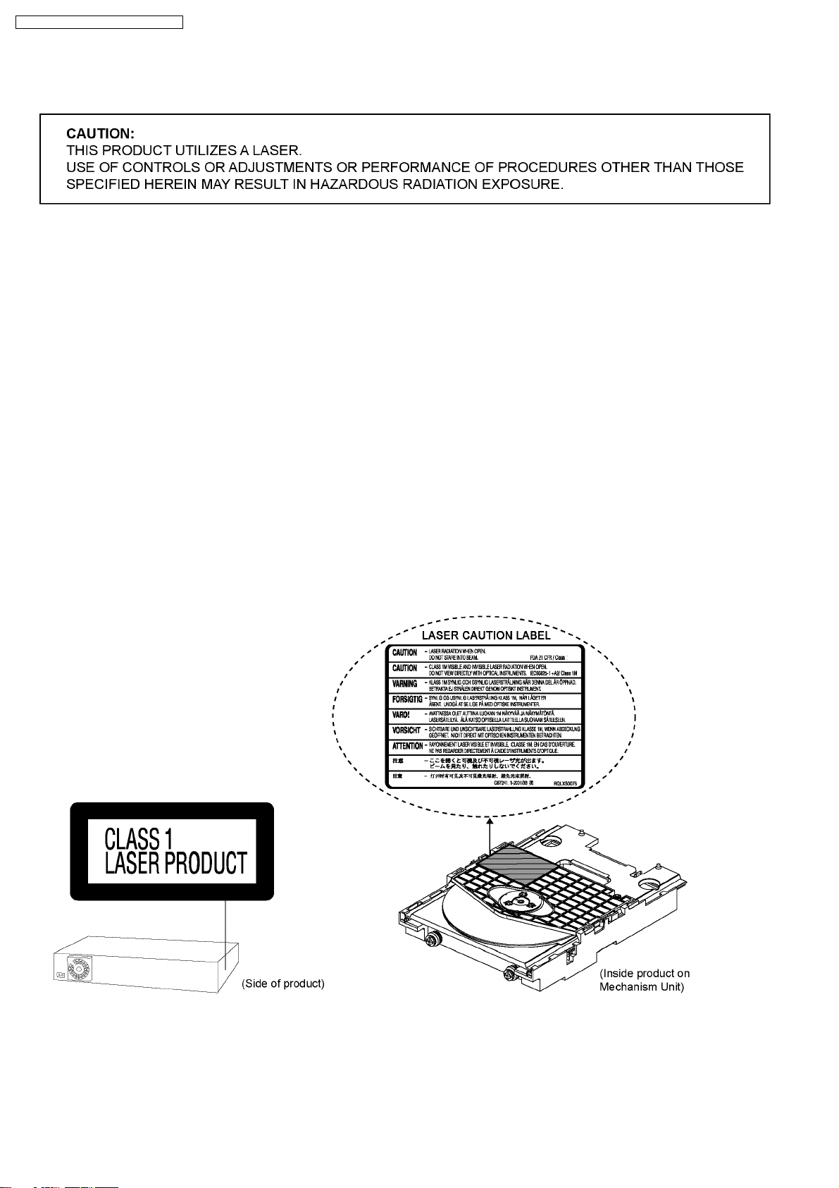
3 Precaution of Laser Diode
CAUTION :
This product utilizes a laser diode with the unit turned "on", invisible laser radiation is emitted from the pickup lens.
Wavelength: 655 nm (DVD)/785 nm (CD)
Maximum output radiation power from pickup: 100 µW/VDE
Laser radiation from the pickup unit is safety level, but be sure the followings:
1. Do not disassemble the pickup unit, since radiation from exposed laser diode is dangerous.
2. Do not adjust the variable resistor on the pickup unit. It was already adjusted.
3. Do not look at the focus lens using optical instruments.
4. Recommend not to look at pickup lens for a long time.
ACHTUNG :
Dieses Produkt enthält eine Laserdiode. Im eingeschalteten Zustand wird unsichtbare Laserstrahlung von der
Lasereinheitadgestrahit.
Wellenlänge: 655 nm (DVD)/785 nm (CD)
Maximale Strahlungsleistung der Lasereinhelt: 100 µW/VDE
Die strahlungan der Lasereinheit ist ungefährlich, wenn folgende Punkte beachtet werden:
1. Die Lasereinheit nicht zerlegen, da die Strahlung an der freigelegten Laserdiode gefährlich ist.
2. Den werksseitig justierten Einstellregler der Lasereinheit nicht verstellen.
3. Nicht mit optischen Instrumenten in die Fokussierlinse blicken.
4. Nicht über längere Zeit in die Fokussierlinse blicken.
10

SA-PT860E / SA-PT860EB / SA-PT860EG
4 About Lead Free Solder (PbF)
4.1. Service caution based on legal restrictions
4.1.1. General description about Lead Free Solder (PbF)
The lead free solder has been used in the mounting process of all electrical components on the printed circuit boards used for this
equipment in considering the globally environmental conservation.
The normal solder is the alloy of tin (Sn) and lead (Pb). On the other hand, the lead free solder is the alloy mainly consists of tin
(Sn), silver (Ag) and Copper (Cu), and the melting point of the lead free solder is higher approx.30 degrees C (86°F) more than that
of the normal solder.
Definition of PCB Lead Free Solder being used
The letter of “PbF” is printed either foil side or components side on the PCB using the lead free solder.
(See right figure)
Service caution for repair work using Lead Free Solder (PbF)
•
• The lead free solder has to be used when repairing the equipment for which the lead free solder is used.
• •
(Definition: The letter of “PbF” is printed on the PCB using the lead free solder.)
•
• To put lead free solder, it should be well molten and mixed with the original lead free solder.
• •
•
• Remove the remaining lead free solder on the PCB cleanly for soldering of the new IC.
• •
•
• Since the melting point of the lead free solder is higher than that of the normal lead solder, it takes the longer time to melt
• •
the lead free solder.
•
• Use the soldering iron (more than 70W) equipped with the temperature control after setting the temperature at 350±30
• •
degrees C (662±86°F).
Recommended Lead Free Solder (Service Parts Route.)
•
• The following 3 types of lead free solder are available through the service parts route.
• •
RFKZ03D01K-----------(0.3mm 100g Reel)
RFKZ06D01K-----------(0.6mm 100g Reel)
RFKZ10D01K-----------(1.0mm 100g Reel)
Note
* Ingredient: tin (Sn), 96.5%, silver (Ag) 3.0%, Copper (Cu) 0.5%, Cobalt (Co) / Germanium (Ge) 0.1 to 0.3%
11
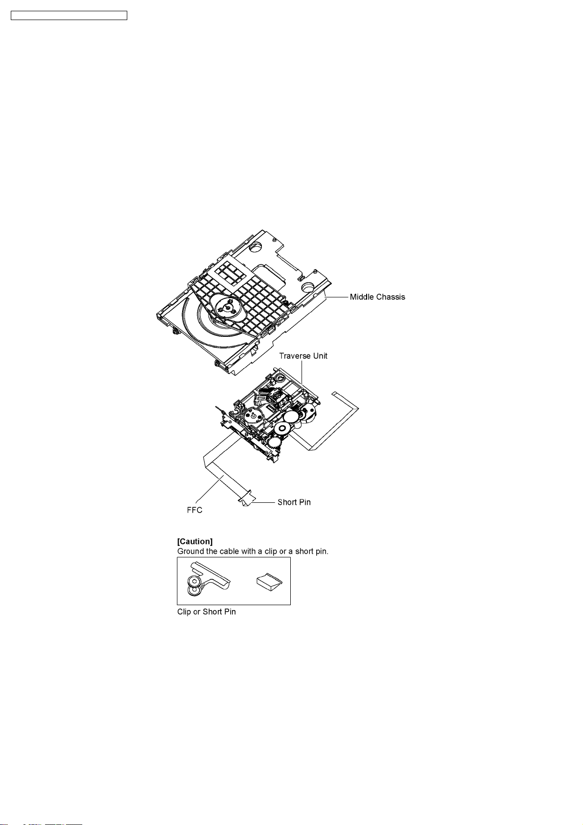
SA-PT860E / SA-PT860EB / SA-PT860EG
5 Handling Precautions for Traverse Unit
The laser diode in the optical pickup unit may break down due to static electricity of clothes or human body. Special care must be
taken avoid caution to electrostatic breakdown when servicing and handling the laser diode in the traverse unit.
5.1. Cautions to Be Taken in Handling the Optical Pickup Unit
The laser diode in the optical pickup unit may be damaged due to electrostatic discharge generating from clothes or human body.
Special care must be taken avoid caution to electrostatic discharge damage when servicing the laser diode.
1. Do not give a considerable shock to the optical pickup unit as it has an extremely high-precise structure.
2. To prevent the laser diode from the electrostatic discharge damage, the flexible cable of the optical pickup unit removed should
be short-circuited with a short pin or a clip.
3. The flexible cable may be cut off if an excessive force is applied to it. Use caution when handling the flexible cable.
4. The antistatic FPC is connected to the new opticalpickup unit. After replacing the optical pickup unit and connecting the flexible
cable, cut off the antistatic FPC.
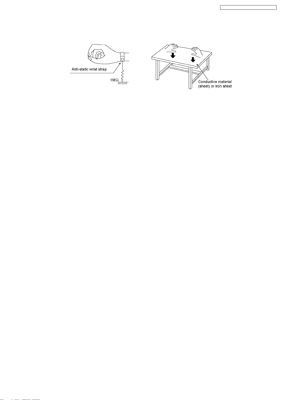
5.2. Grounding for electrostatic breakdown prevention
Some devices such as the DVD player use the optical pickup (laser diode) and the optical pickup will be damaged by static
electricity in the working environment. Proceed servicing works under the working environment where grounding works is
completed.
5.2.1. Worktable grounding
1. Put a conductive material (sheet) or iron sheet on the area where the optical pickup is placed, and ground the sheet.
5.2.2. Human body grounding
1. Use the anti-static wrist strap to discharge the static electricity form your body.
12
SA-PT860E / SA-PT860EB / SA-PT860EG
13
SA-PT860E / SA-PT860EB / SA-PT860EG
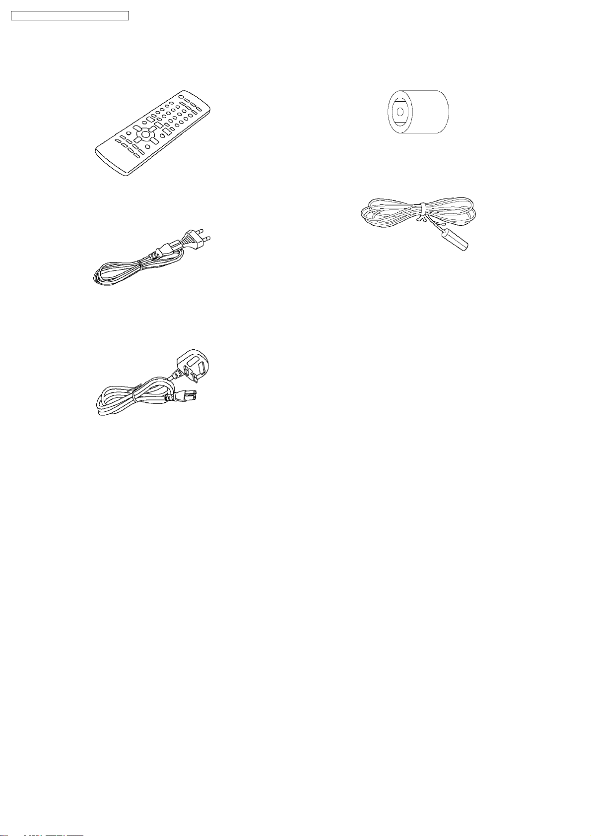
6 Accessories
•
• Note: Refer to “Replacement Parts List” (Section 25) for the part number.
• •
Remote control
AC cord
(E/EG only)
Antenna plug
adaptor
FM indoor antenna
AC cord
(EB only)
14
7 Operation Procedures
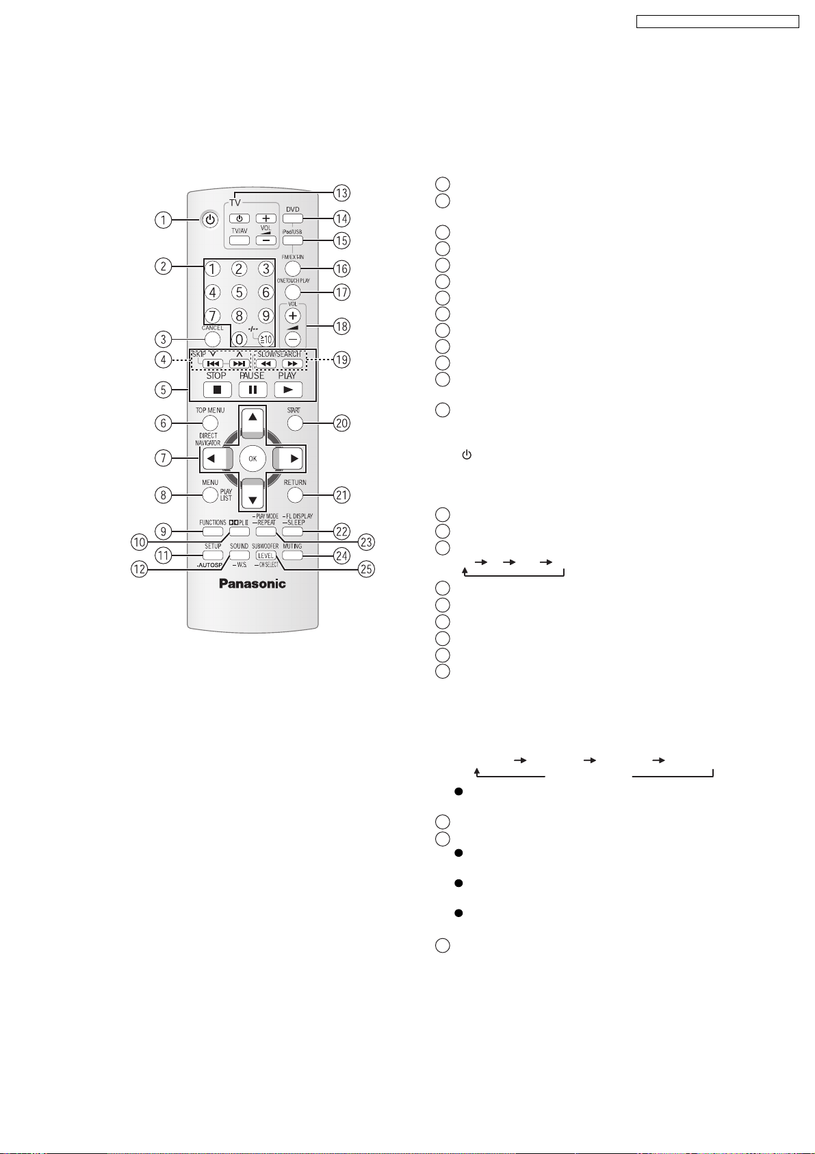
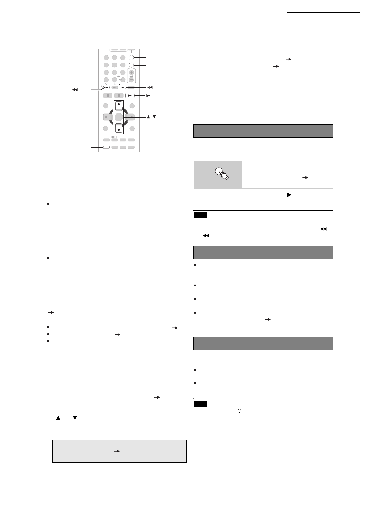
7.1. Remote Control Key Buttons Operations
1
Turn this unit on/off
2
Select channels and title numbers etc. / Enter
numbers
3
Cancel
4
Select preset radio stations
5
Basic operations for play
6
Show a disc top menu or program list
7
Select or confirm menu items / Frame-by-frame
8
Show a disc menu or play list
9
Show on-screen menu / Display RDS text data
10
Turn Dolby Pro Logic II on/off
11
Show setup menu / Auto speaker setup
12
Select sound effect to set / Turn Whisper-mode
Surround on/off
13
TV op eratio ns
Aim the remote control at the Panasonic TV and
press the button.
: Turn the TV on/off
[]
[TV/AV]: Change the TV s video input mode
[, ]:
+-
This may not work properly with some models.
Select disc as the source
14
Select USB or iPod as the source
15
16
Select FM tuner or external audio as the source
FM AV AU D-IN
Adjust the TV volume
X
SA-PT860E / SA-PT860EB / SA-PT860EG
Start up and play a disc automatically
17
Adjust the volume of this unit
18
Select radio stations manually
19
Show START menu
20
Return to previous screen
21
22
Switch information on this unit s display
or
Set the Sleep timer
Press and hold [-SLEEP].
While the time is shown on this unit display, press
the [-SLEEP] repeatedly.
SLEEP 30 SLEEP 60 SLEEP 90 SLEEP120
OFF (Cancel )
To confirm the remaining time, press and hold the
button again.
Select the play mode / Set the rep
23
24
Mute the sound
"MUTING" flashes in this unit s display while the
function is on.
To cancel, press the button again or adjust the
volume.
Muting is cancelled when you switch the unit to
standby.
Adjust the subwoofer level or select speaker channel
25
eat mo
de
15
SA-PT860E / SA-PT860EB / SA-PT860EG
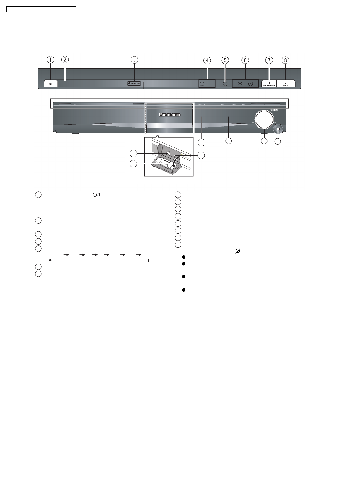
7.2. Main Unit Key Buttons Operations
O
P
E
N
C
L
O
S
E
9
12
SW
B
O
O
ST
11
13
10
Standby/on switch [ ]
1
Press to switch the unit from on to standby mode or
vice versa. In standby mode, the unit is still
consuming a small amount of power.
This indicator lights when the unit is connected to the
2
AC mains supply.
Open/Close the disc tray3
Turn Subwoofer Boost on/off4
5 Select the source
DVD/CD USB FM AV AUX D-IN IPOD
Skip or slow-search play / Select the radio stations6
Stop playing / Select the tuning mode / Adjust the
7
FM reception condition
Play discs / Memorize the receiving radio stations8
Connect USB device9
Connect iPod
10
Connect Auto speaker setup microphone
11
Remote control signal sensor
12
Display
13
Adjust the volume of this unit
14
Connect headphones (not included)
15
Headphone plug type: 3.5 mm stereo mini plug
Reduce the volume before connecting.
Audio is automatically switched to 2-channel
stereo.
To prevent hearing damage, avoid listening for
prolonged periods of time.
Excessive sound pressure from earphones and
headphones can cause hearing loss.
14
15
16
7.3. Using the VIERA Link “HDAVI Control™”
SA-PT860E / SA-PT860EB / SA-PT860EG
FM/EXT-IN
3
SKIP
12
4
7
CANCEL
SKIP
6
5
89
10
0
SLOW/SEARCH
ONE TOUCH PLAY
PLAYPAUSESTOP
VOL
FM/EXT-IN
ONE T OUCH PLAY
SLOW/SEARCH
PLAY
SETUP
TOP MENU
DIRECT
NAVIGATOR
MENU
PLAY
LIST
FUNCTIONS
SETUP SOUND
START
OK
RETURN
-
FL DISPLAY
-
PLAY MODE
-
SLEEP
-
REPEAT
PL
MUTING
SUBWOOFER
LEVEL
-
CH SELECT
-
W.S.
VIERA Link HD AVI Control
VIERA Link HDAVI Control is a convenient function that
offers linked operations of this unit, and a Panasonic TV
(VIERA) under HDAVI Control . You can use this
function by connecting the equipment with the HDMI
cable. See the operating instructions for connected
equipment for operational details.
VIERA Link HDAVI Control , based on the control
functions provided by HDMI which is an industry
standard known as HDMI CEC (Consumer Electronics
Control), is a unique function that we have developed
and added. As such, its operation with other
manufacturers equipment that supports HDMI CEC
cannot be guaranteed (Refer to the operating
instructions for your equipment).
This unit supports HDAVI Control 3 function.
HDAVI Control 3 is the newest standard (current as of
December, 2007) for Panasonic s HDAVI Control
compatible equipment. This standard is compatible with
Panasonic s conventional HDAVI equipment.
The TV with HDAVI Control 2 (or later) function enables
the following operation: VIERA Link Control only with
TV s remote control [for HDAVI Control 2 (or later) ]
(29).
Preparation
Confirm that the HDMI connection has been made ( 10).
Set VIERA Link to ON ( 26, HDMI menu).
To complete and activate the connection correctly, turn
on all VIERA Link HDAVI Control compatible
equipment and set the TV to the corresponding HDMI
input mode for this unit.
Setting the TV audio for VIERA Link HDAVI Control
Select between
AUX
and D-IN to work with the linked
operations.
Confirm the audio connection to the
AUX
) or OPTICAL IN terminal (for D-IN ) ( 11).
1 Press [FM/EXT-IN] to select
AUX
AUX
terminal (for
or D-IN .
2 Press [SETUP] to select TV AUDIO , then press
AUX
[ ] or [ ] to switch to
or D-IN .
Whenever the connection or settings are changed,
reconfirm the points above.
*
AUX
or D-IN ( DIGITAL IN ) works depending on
the TV AUDIO setting ( above, Setting the TV
audio for VIERA Link HDAVI Control ).
Automatic setup
The settings for TV ASPECT*1 ( 24, VIDEO
menu) and LANGUAGE
will automatically follow to the settings of the TV.
(This may not work if the corresponding setting you
have made for your TV is not available on this unit.)
*1
When using VIERA Link HDAVI Control with
HDAVI Control 3 compatible TV
*2
When using VIERA Link HDAVI Control with
HDAVI Control 2 (or later) compatible TV
One touch play
You can turn on this unit and the TV, and start playing the
disc with a single press of a button.
ONE TOUCH PLAY
Start disc playback.
This unit s speakers will be
automatically activated ( 29).
This function also works if you press [ PLAY] on this
unit s remote control when this unit is in standby mode.
Note
Playback may not be immediately displayed on the TV. If
you miss the beginning portion of playback, press [ ]
or [ ] to go back to where playback started.
Auto i nput switching
When you switch the TV input to TV tuner mode, this
unit will automatically switch to
does not work when this unit is in IPOD mode.)
When you select DVD/CD as the source, the TV will
automatically switch its input mode for this unit.
DVD-V VCD
When playback stops, the TV will
automatically return to TV tuner mode.
When you select
AUX* or DIGITAL IN* from Input
Selection in START menu ( 15), the TV will
automatically switch to TV tuner mode.
Power off link
When the TV is turned off, this unit goes into standby
mode automatically.
This function works only when DVD/CD ,
AUX* or D-IN*is selected as the source on this unit.
When the TV is turned on, this unit does not turn on
automatically. (Power on link is not available.)
Note
When you press [ ], only this unit turns off. Other
connected equipment compatible with VIERA Link
HDAVI Control stays on.
*2
( 25, DISPLAY menu)
AUX* or D-IN*. (This
USB ,
17
SA-PT860E / SA-PT860EB / SA-PT860EG
Speaker control VIERA Link Control only with TV remote
You can select whether audio is output from this unit s
speakers or the TV speakers by using the TV menu
settings. For details, refer to the operating instructions of
your TV.
Home Cinema
This unit s speakers are active.
When this unit is in standby mode, changing the TV
speakers to this unit s speakers in the TV menu will
automatically turn this unit on and select AUX
*
D-IN
as the source.
The TV speakers are automatically muted.
You can control the volume setting using the volume or
mute button on the TV s remote control. (The volume
level is displayed on this unit s FL display.)
To cancel muting, you can also use this unit s remote
control ( 14).
If you turn off this unit, TV speakers will be
automatically activated.
*
or
control [for HD AVI Control 2 (or later) ]
You can control the playback menus of this unit with the
TV s remote control. When operating the TV s remote
control, refer to the below illustration for operation
buttons.
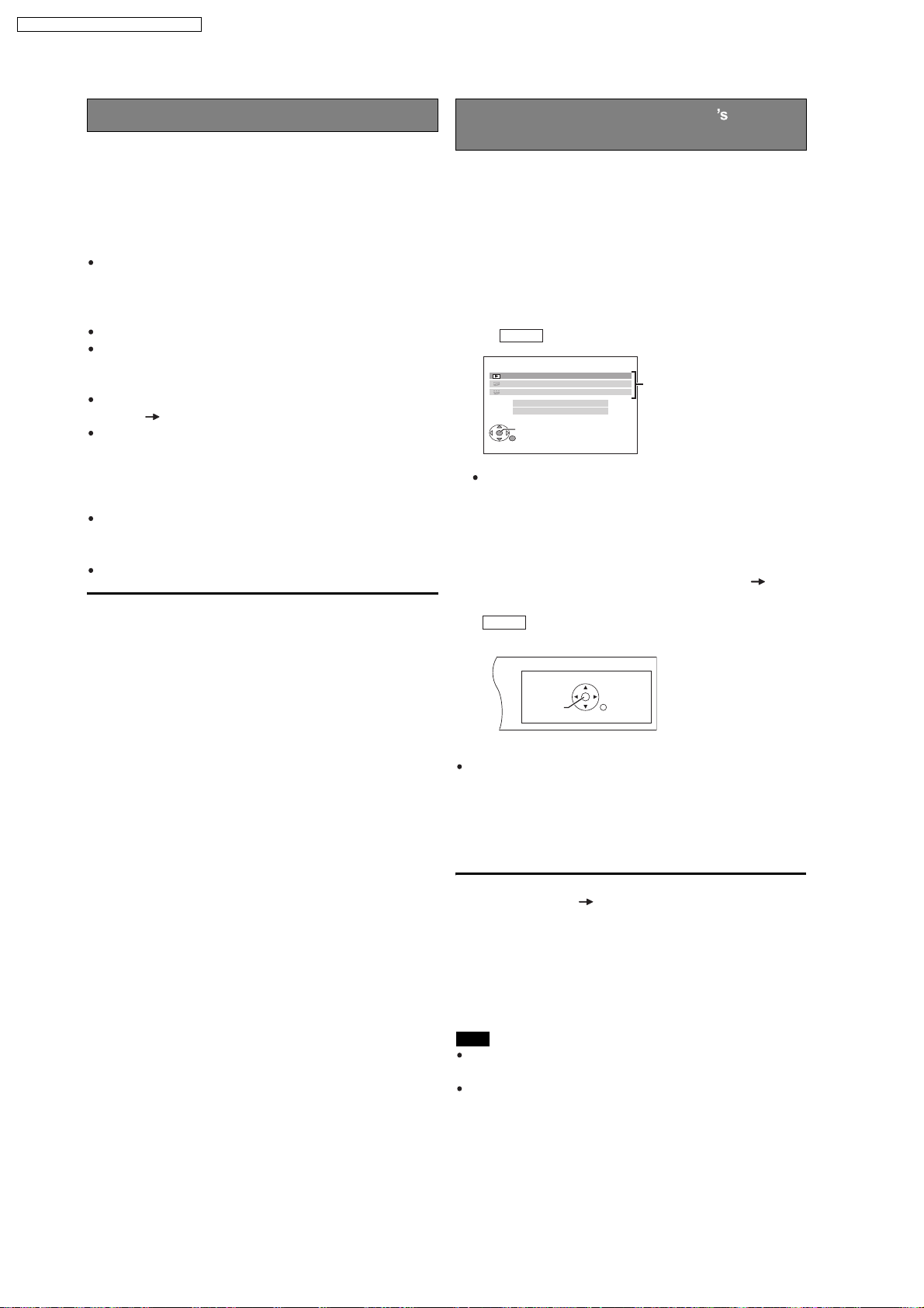
1 Select this unit s operation menu by using the TV
menu settings.
(For details, refer to the operating instructions of your
TV.)
The START menu will be shown.
e.g. DVD-V
DVD/CD Home Cinema
Playback Disc
TOP MENU (DVD)
MENU (DVD)
Input Selection
Sound
OK
RETURN
Playback/
menu access
TV
TV speakers are active.
The volume of this unit is set to 0 .
This function works only when DVD/CD , USB ,
*
AUX
or D-IN*
is selected as the source on this unit.
Audio output is 2-channel audio.
When switching between this unit s speakers and TV
speakers, the TV screen may be blank for several
seconds.
The START menu can also be shown by using a
button on the TV s remote control (e.g. [OPTION]).
When
DVD/CD or
USB is selected as the source,
this works only during stop mode.
This does not work while iPod music playback
screen is displayed on the TV.
2 Select the desired item on the START menu ( 15).
When the on-screen control panel appears
e.g. DVD-V (when Playback Disc is selected from the
START menu)
PAUSE
SEARCH
PLAY
STOP
SEARCH
RETURN
You can operate the playback with the indicated controls.
The on-screen control panel can also be shown by
using a button on the TV s remote control (e.g.
[OPTION]).
This works only during
DVD/CD or
USB playback
and resume modes or, while iPod music playback
screen is displayed on the TV.
If the TV has automatically switched to the HDMI input
mode for this unit (
28, Auto input switching
)
When you press [EXIT] button on the TV s remote control
to exit VIERA Link Control, the TV will automatically
switch to TV tuner mode. (This does not work when this
unit is in IPOD mo de or, during playback or resume
mode when
DVD/CD or
USB is selected as the
source.)
Note
Depending on the menu, some button operations
cannot be performed from the TV s remote control.
You cannot input numbers with the numbered buttons
on the TV s remote control ([0] to [9]). Use this unit s
remote control to select the play list etc.
18
7.4. Using the iPod
SA-PT860E / SA-PT860EB / SA-PT860EG
Preparation
To view photos/videos from the iPod
Ensure the video connection to the SCART (AV)
terminal on this unit and select "VIDEO" from "VIDEO
OUT SCART" in "VIDEO" menu
Operate the iPod menu to make the appropriate photo/
video output settings for your TV. (Refer to operating
instructions of your iPod.)
To display the picture, turn on the TV and select the
appropriate video input mode.
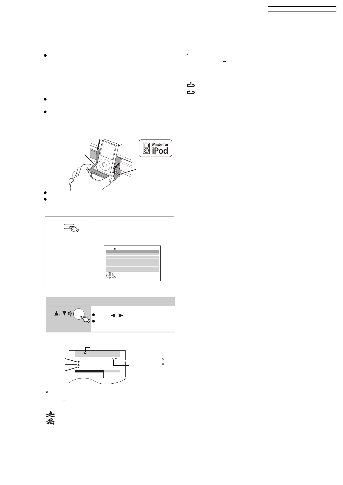
Before connecting/disconnecting the iPod, turn this unit
off or reduce the volume of this unit to its minimum.
Connect the iPod (not included) firmly.
Recharging starts when the iPod is inserted.
e.g.
Dock adapter
(not included)
iPod
Dock for iPod
This unit
Hold the dock when connecting/disconnecting the iPod.
Attach the dock adapter which should be supplied with
your iPod to the dock for the stable use of the iPod.
If you need an adapter, consult your iPod dealer.
iPod/USB
Select "IPOD".
The iPod automatically switches to
this unit’s display mode.
Music menu appears on the TV.
e.g.
iPod Home Cinema
Playlists
Artists
Albums
Song s
Podcasts
Genres
Composer s
Audiobooks
OK
2
To select repeat modes
Press and hold and then press the button
[]
REPEAT
repeatedly within 3 seconds.
Each time you press the button:
: Repeat 1 track
: Repeat all
Off: Cancel
To operate through display of iPod, press [FUNCTIONS].
Enjo ying m usic
Select an item.
OK
Press [ ] to skip page by page.
To return to the previous screen,
press [RETURN].
Play starts from the selected song.
e.g.
Song
Artist
Album
1
To select shuffle modes
[
Press
PLAY MODE
Playback condition
iPod Home Cinema
3/ 20
Good mornin g
Ronaldo
Happy da ys
2:43 -1:15
RETURN
]
Shuffle mode
Repeat mode
Current position
1
2
Each time you press the button:
: Song shuffle
: Album shuffle
Off: Cancel
19
SA-PT860E / SA-PT860EB / SA-PT860EG
Enjoying photos/videos
FUNCTIONS
1
Play a slideshow or video on your iPod.
2
The picture will be displayed on your TV.
You can also use the remote control to operate iPod
menu.
]: To navigate menu items
[
[OK]: To go to the next menu
[RETURN]: To return to the previous menu
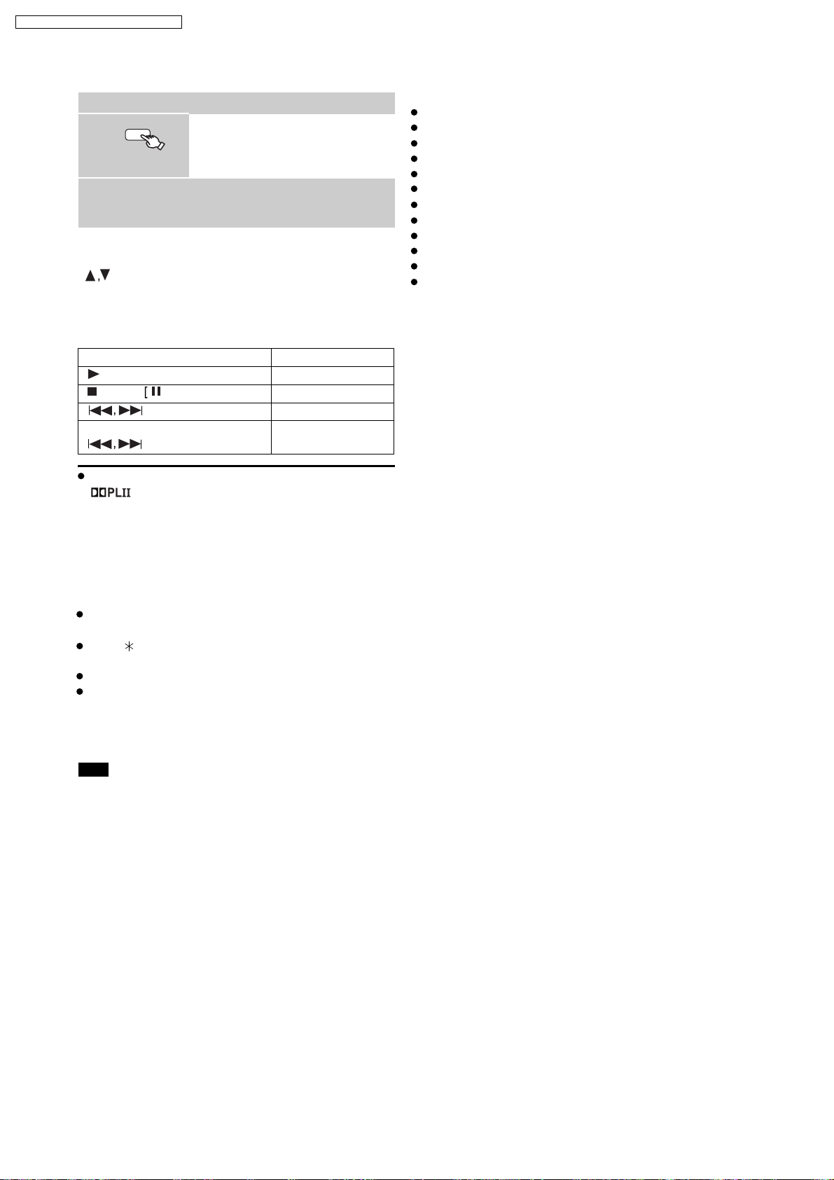
Basic controls (For music and videos only)
Button Function
[ PLAY] Play
[STOP],
[
(press and hold)
[
You can enjoy surround sound effect when you press
[ ] to turn on Dolby Pro Logic II
] Skip
]
Switch the iPod to its own display
mode.
Proceed operations through display
of iPod.
PAUSE] Pause
Search
Compatible iPod
iPod touch (8GB, 16GB)
iPod nano 3rd generation (video) (4GB, 8GB)
iPod classic (80GB, 160GB)
iPod nano 2nd generation (aluminum) (2GB, 4GB, 8GB)
iPod 5th generation (video) (60GB, 80GB)
iPod 5th generation (video) (30GB)
iPod nano 1st generation (1GB, 2GB, 4GB)
iPod 4th generation (color display) (40GB, 60GB)
iPod 4th generation (color display) (20GB, 30GB)
iPod 4th generation (40GB)
iPod 4th generation (20GB)
iPod mini (4GB, 6GB)
Compatibility depends on the software version of your
iPod.
When using the START menu in "IPOD" mode
Select "Music" or "Photos/Videos".
Music: Shows the music menu.
Photos/Videos: Switches to display of iPod.
About recharging the battery
iPod will start recharging regardless of whether this unit
is on or off.
"IPOD " will be shown on this unit’s display during
iPod charging in this unit standby mode.
Check iPod to see if the battery is fully recharged.
If you are not using iPod for an extended period of time
after recharging has completed, disconnect it from this
unit, as the battery will be depleted naturally. (Once fully
recharged, additional recharging will not occur.)
Note
When connecting the iPod, ensure the USB device has
been disconnected.
20
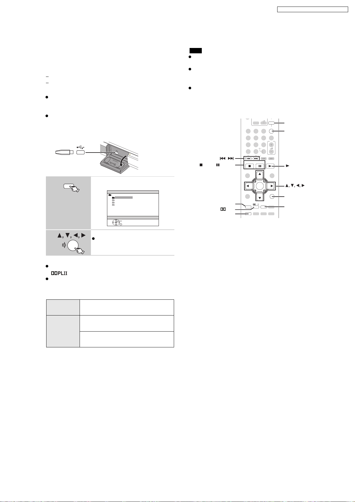
7.5. USB Connection and Operation
You can connect and play tracks or files from USB mass
storage class devices.
Devices which are defined as USB mass storage class:
USB devices that support bulk only transfer.
USB devices that support USB 2.0 full speed.
Preparation
Before connecting any USB mass storage device to the
unit, ensure that the data stored therein has been
backed up.
It is not recommended to use a USB extension cable.
The USB device connected using the cable will not
recognised by this unit.
Connect the USB device (not included).
USB device
iPod/USB
1
O
P
E
N
C
L
O
S
E
SW
B
O
O
S
T
This unit
Select "USB".
The menu screen appears.
USB
e.g.
ROOT
Songs
Concer t_01
Concer t_02
Southern AI
OK
SA-PT860E / SA-PT860EB / SA-PT860EG
Note
Maximum: 256 folders, 4000 files, 12 characters for file/
folder name
Only one memory card will be selected when
connecting a multiport USB card reader. Typically the
first memory card inserted.
When connecting the USB mass storage device, ensure
the iPod has been disconnected.
VOL
TV/AV
iPod/USB
iPod/USB
FM/EXT-IN
,
STOP, PAUSE
FUNCTIONS
PLII
SETUP
12
4
7
CANCEL
SKIP
TOP MENU
DIRECT
NAVIGATOR
MENU
FUNCTIONS
SETUP
5
89
0
PLAY
LIST
PL
SOUND
-
W.S.
3
6
10
SLOW/SEARCH
OK
-
PLAY MODE
-
REPEAT
SUBWOOFER
LEVEL
-
CH SELECT
ONE TOUCH PLAY
PLAYPAUSESTOP
VOL
START
RETURN
-
FL DISPLAY
-
SLEEP
MUTING
FM/EXT-IN
PLAY
OK
RETURN
-PLAY MODE
—
REPEAT
2
OK
Select an item.
To return to the previous screen,
press [RETURN]
.
Play starts from the selected content.
You can enjoy surround sound effect when you press
[ ] to turn on Dolby Pro Logic II
For other operating functions, they are similar to those
described in "Playing discs"
Supported Formats
Still
pictures
JPEG (Extension: ".jpg", ".JPG", ".jpeg",
".JPEG")
Music MP3 (Extension: ".mp3", ".MP3")
WMA (Extension: ".wma", ".WMA")
*Video MPEG4 (Extension: ".asf", ".ASF")
* For E/EG only
21

SA-PT860E / SA-PT860EB / SA-PT860EG
7.6. Audio and Video Connection
7.6.1. Basic Setup
Basic Setup Example
TV
(not included)
AV1
Scart Cable
(not Included)
AV
AV2
Scart Cable
VOLUME
This Unit
AV O UT
(not Included)
Set top box or video cassette recorder
(not included)
This connection will also enable you to play TV audio through your home theater system
Select the appropriate audio out (e.g., Monitor) on the TV.
When both the HDMI cable and scart cable are
connected, there will be no RGB output from the
SCART (AV) terminal.
7.6.2. Connecting to a Television with HDMI & Component Video Out Terminal
TV terminal
Cable required
(not included)
HDMI cable
AV IN
COMPONENT
VIDEO IN
Panasonic televisions
with 576/50i-50p, 480/
60i-60p input terminals
are progressive
compatible. Consult
the manufacturer if you
have another brand of
television.
Note
Do not make the video connections through the video cassette recorder.
Due to copy guard protection, the picture may not be displayed properly.
Only one video connection is required. Choose one of the video connections above depending on your TV.
[Note]
Non-HDMI-compliant
cables cannot be utilized.
It is recommended that
you use Panasonic s HDMI
cable. Recommended part
number:
RP-CDHG15 (1.5 m),
RP-CDHG30 (3.0 m),
RP-CDHG50 (5.0 m), etc.
Video cables
PR
PB
Y
This unit terminal
HDMI
COMPONENT VIDEO OUT
P
R
P
B
Y
COMPONENT VIDEO OUT
Connect to
terminals of the
same colour.
This connection provides the best picture quality.
Set
(
Set VIDEO FORMAT in Menu 4 (HDMI) ( 22).
VIERA Link HD AVI Control
If your Panasonic TV is
compatible, you can operate it
synchronising with home theater
operations or vice versa ( 28, Using the
VIERA Link HDAVI Control
Make the extra audio connection ( 11)
when you use
Control
This connection provides a much purer
picture than the SCART (AV) terminal.
When making this connection, select VIDEO/
YPbPr or S-VIDEO/YPbPr in
SCAR T
OUTPUT
selected, no signal is output from the
component video terminals. ( 24)
To enjoy progressive video
Connect to a progressive output
compatible television.
Set VIDEO OUT (I/P) in VIDE O
menu to PROGRESSIVE and then
follow the instructions on the menu
screen ( 24, VIDEO menu).
Features
VIDEO PRIORITY
26, HDMI menu
VIERA Link
function.
in VIDEO menu. If
or
RGB 2/NO OUTPUT
to ON
).
VIERA Link
TM
).
HDAVI
VIDEO OUT
RGB 1/NO
is
22
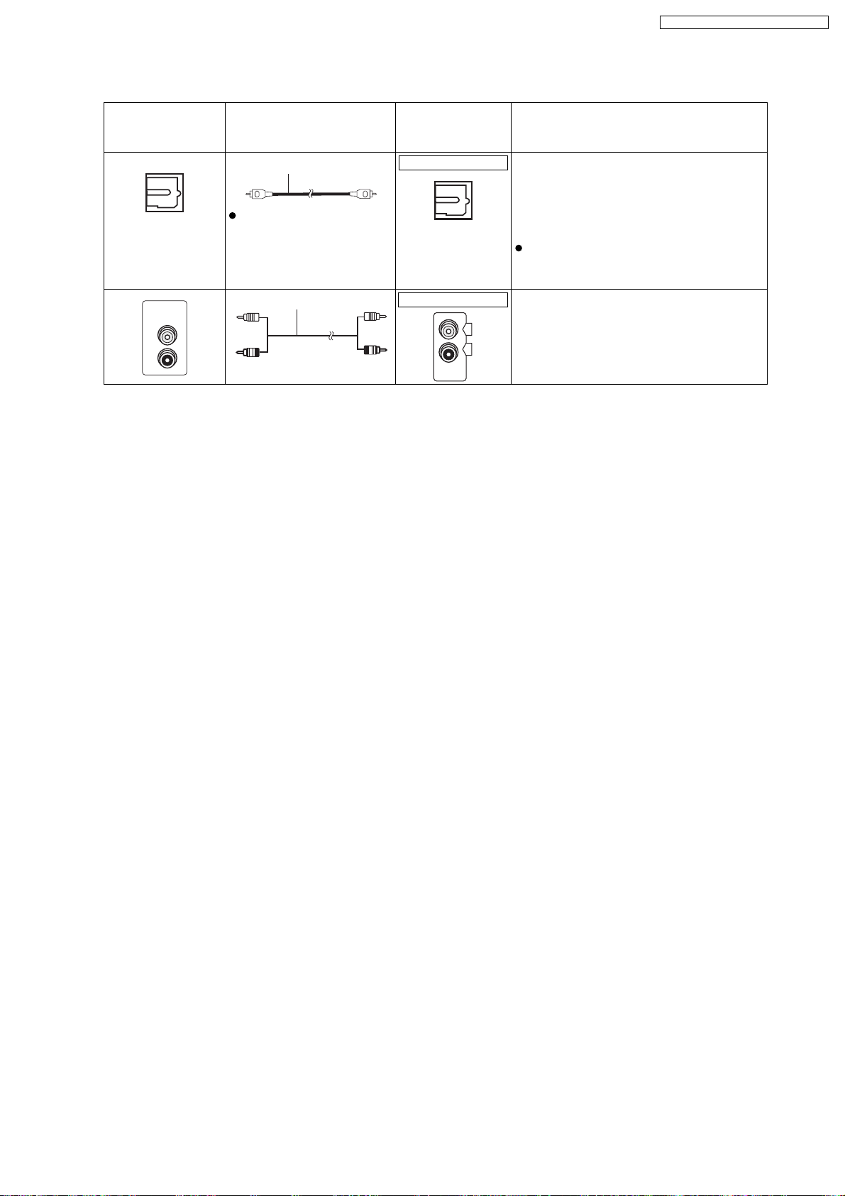
7.6.3. Connecting to a Television with Optical & AUX Terminal
SA-PT860E / SA-PT860EB / SA-PT860EG
TV or external
equipment
terminal
OPTICAL OUT
AUDIO
OUT
L
R
Cable required
(not included)
Optical digital audio cable
Do not bend sharply when
connecting.
Audi o cab le This connection enables you to play audio
This unit terminal Features
OPTICAL IN
This unit can decode the surround signals
received through the set top box, digital
broadcasting or satellite broadcasts. Refer
to your equipment’s operating instructions
OPTICAL
IN
for details. Only Dolby Digital and PCM can
be played with this connection.
After making this connection, make
settings to suit the type of audio from your
digital equipment
AUX
from your TV, set top box or video cassette
L
R
AUX
recorder through your home theater
system
23
SA-PT860E / SA-PT860EB / SA-PT860EG
7.7. Disc Information
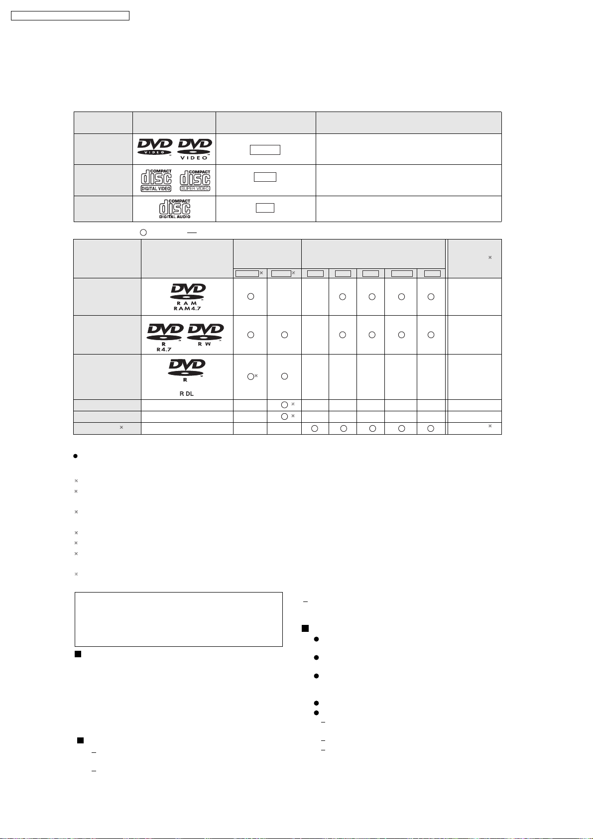
7.7.1. Disc Playability (Media)
Commercial discs
Disc Logo
Indicated in these
instructions by
Remarks
DVD-Video
Video CD
CD
Recorded discs ( : Playable,
Disc Logo
DVD-RAM
DVD-R/RW
DVD-R DL
+ +
R/ RW
+
R
DL
CD-R/RW
1
DVD-V
VCD
CD
: Not playable)
Recorded on a
DVD vid e o
recorder, etc.
2
DVD-VR4DVD-V WMA JPEGMP3 MPEG4*DivX
——
3
——() ——— — —
——() ——— — —
———
High quality movie and music discs
Music discs with video
Including SVCD (Conforming to IEC62107)
Music discs
Recorded on a personal computer, etc.
*
—
——— — —
5
5
Finalizing
Not necessary
Necessary
Necessary
Necessary
Necessary
Necessary
6
7
* For E/EG only
It may not be possible to play all the above-mentioned discs in some cases due to the type of disc, the condition of
the recording, the recording method, or how the files were created. [Refer to Section 7.7.2. File Extension Type Support
1
This unit can play CD-R/RW recorded with CD-DA or Video CD format.
2
Discs recorded on DVD recorders or DVD video cameras, etc. using Version 1.1 of the Video Recording Format (a
unified video recording standard).
3
Discs recorded on DVD recorders or DVD video cameras using Version 1.2 of the Video Recording Format (a
unified video recording standard).
4
Discs recorded on DVD recorders or DVD video cameras using DVD-Video Format.
5
Recorded using a format different from DVD-Video Format, therefore some functions cannot be used.
6
A process that allows play on compatible equipment. To play a disc that is indicated as "Necessary", the disc must
first be finalized on the device it was recorded on.
7
Closing the session will also work.
WMA/MP3/JPEG/MPEG4/DIVX)]
Note about using a DualDisc
The digital audio content side of a DualDisc does not
meet the technical specifications of the Compact Disc
Digital Audio (CD-DA) format so playback may not be
possible.
Discs that cannot be played
Blu-ray, HD DVD, AVCHD discs, DVD-RW version
1.0, DVD-Audio, DVD-ROM, CD-ROM, CDV, CD-G,
SACD, DivX Video Discs and Photo CD, DVD-RAM
that cannot be removed from their cartridge, 2.6 GB
and 5.2 GB DVD-RAM, and "Chaoji VCD" available
on the market including CVD, DVCD and SVCD that
do not conform to IEC62107.
Video systems
This unit can play PAL and NTSC, but your TV must
match the system used on the disc.
PAL discs cannot be correctly viewed on an NTSC TV.
This unit can convert NTSC signals to PAL 60 for
viewing on a PAL TV.
Disc handing precautions
Do not attach labels or stickers to discs. This may
cause disc warping, rendering it unusable.
Do not write on the label side with a ball-point pen
or other writing instrument.
Do not use record cleaning sprays, benzine,
thinner, liquids which prevent static electricity, or
any other solvent.
Do not use scratch-proof protectors or covers.
Do not use the following discs:
Discs with exposed adhesive from removed
stickers or labels (rented discs, etc.).
Discs that are badly warped or cracked.
Irregularly shaped discs, such as heart shapes.
24
7.7.2. File Extension Type Support (WMA/MP3/JPEG/MPEG4)
e
r
Format Disc Extension Reference
WMA
MP3
JPEG
*MPEG4
*DivX
CD-R/RW . WMA
DVD-RAM
DVD-R/RW
CD-R/RW
DVD-RAM
DVD-R/RW
CD-R/RW
DVD-RAM
DVD-R/RW
CD-R/RW
DVD-RAM
DVD-R/RW
CD-R/RW
.wma
.MP3
.mp3
.JPG
.jpg
.JPEG
.jpeg
.ASF
.asf
.DIVX
.divx
.AVI
.avi
Compatible compression rate: between 48 kbps and 320 kbps
You cannot play WMA files that are copy-protected.
This unit does not support Multiple Bit Rate (MBR: an encoding process for audio content that
produces an audio file encoded at several different bit rates).
This unit does not support ID3 tags.
Sampling frequency and compression rate:
DVD-RAM, DVD-R/RW:
CD-R/RW: 8, 11.02, 12, 16, 22.05, 24 kHz (8 to 160 kbps), 32, 44.1 and 48 kHz (32 to 320 kbps)
JPEG files taken on a digital camera that conform to DCF Standard (Design rule for Camera File
system) Version 1.0 are displayed.
Files that have been altered, edited or saved with computer picture editing software may not be
displayed.
This unit cannot display moving pictures, MOTION JPEG and other such formats, sti d::l pictures othe
than JPEG (e.g. TIFF), or play pictures with attached audio.
You can play MPEG4 data [conforming to SD VIDEO specifications (ASF standard)/MPEG4 (Simple
Profile) video system/G.726 audio system] recorded with Panasonic SD multi cameras or DVD
recorders with this unit.
The recording date may differ from that of the actual date.
Plays all versions of DivX
audio system] with standard playback of DivX
supported.
DivX files greater than 2 GB or have no index may not be played properly on this unTd4t.
This unit supports all resolutions up to maximum of 720k 480 (NTSC)/720k 576 (PAL).
You can select up to 8 types of audio and subtitles on this unit.
11.02, 12, 22.05, 24 kHz (8 to 160 kbps), 44.1 and 48 kHz (32 to 320 kbps)
fi
video (including DivXfi6) [DivX video system/MP3, Dolby Digital or MPEG
fi
media files. Functions added with DivX Ultra are not
SA-PT860E / SA-PT860EB / SA-PT860EG
* For E/EG only
There may be differences in the display order on the menu screen and computer screen.
This unit cannot play files recorded using packet write.
DVD-RAM
Discs must conform to UDF 2.0.
DVD-R/RW
Discs must conform to UDF bridge (UDF 1.02/ISO9660).
This unit does not support multi-session. Only the default session is played.
CD-R/RW
Discs must conform to ISO9660 level 1 or 2 (except for extended formats).
This unit supports multi-session but if there are many sessions it takes more time for play to start. Keep the nhd8mb
of sessions to a minimum to avoid this.
25
SA-PT860E / SA-PT860EB / SA-PT860EG
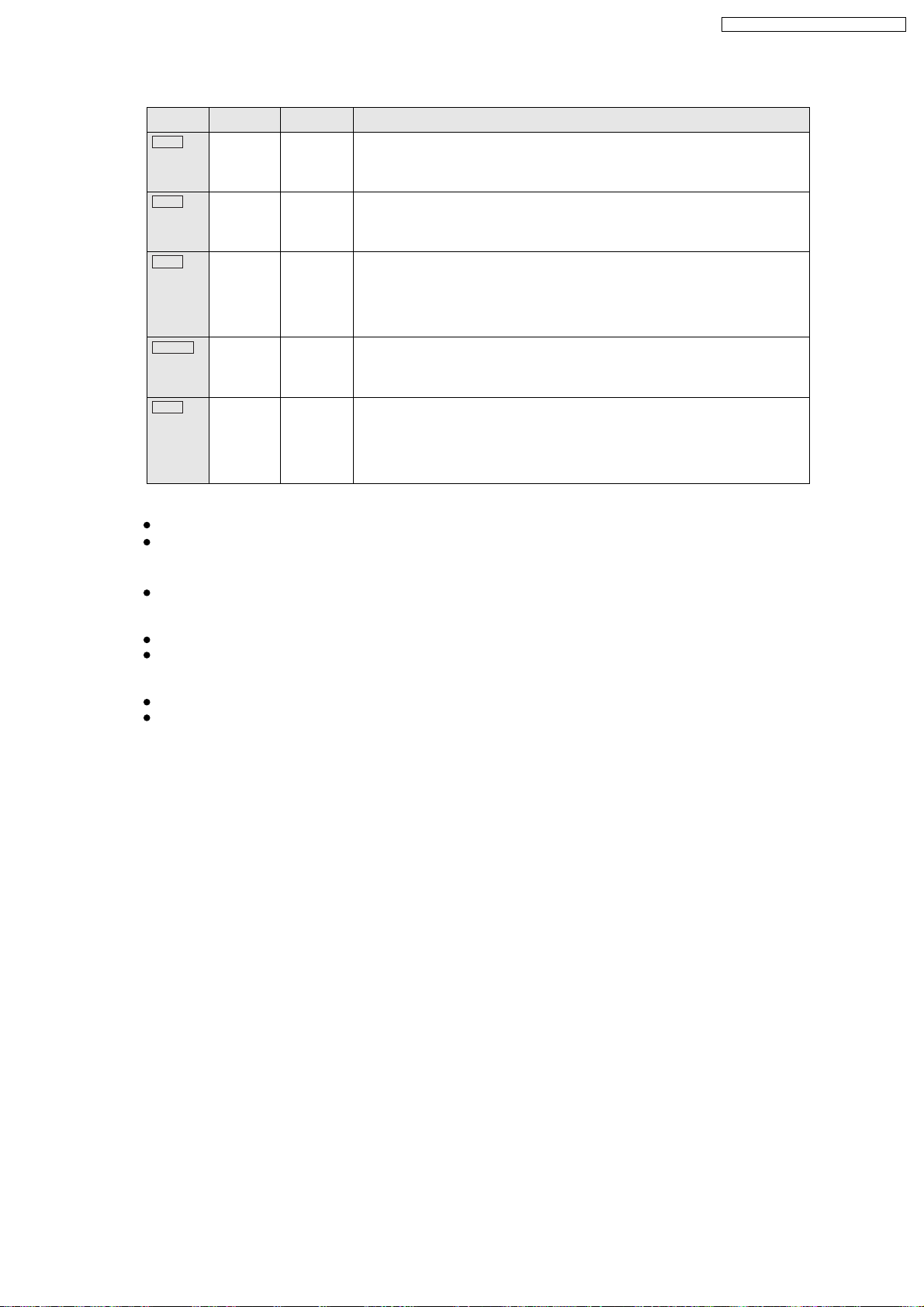
8 Self-Diagnosis and Special Mode Setting
8.1. Service Mode Summary Table
The service modes can be activated by pressing various button combination on the main unit and remote control unit.
Below is the summary for the various modes for checking:
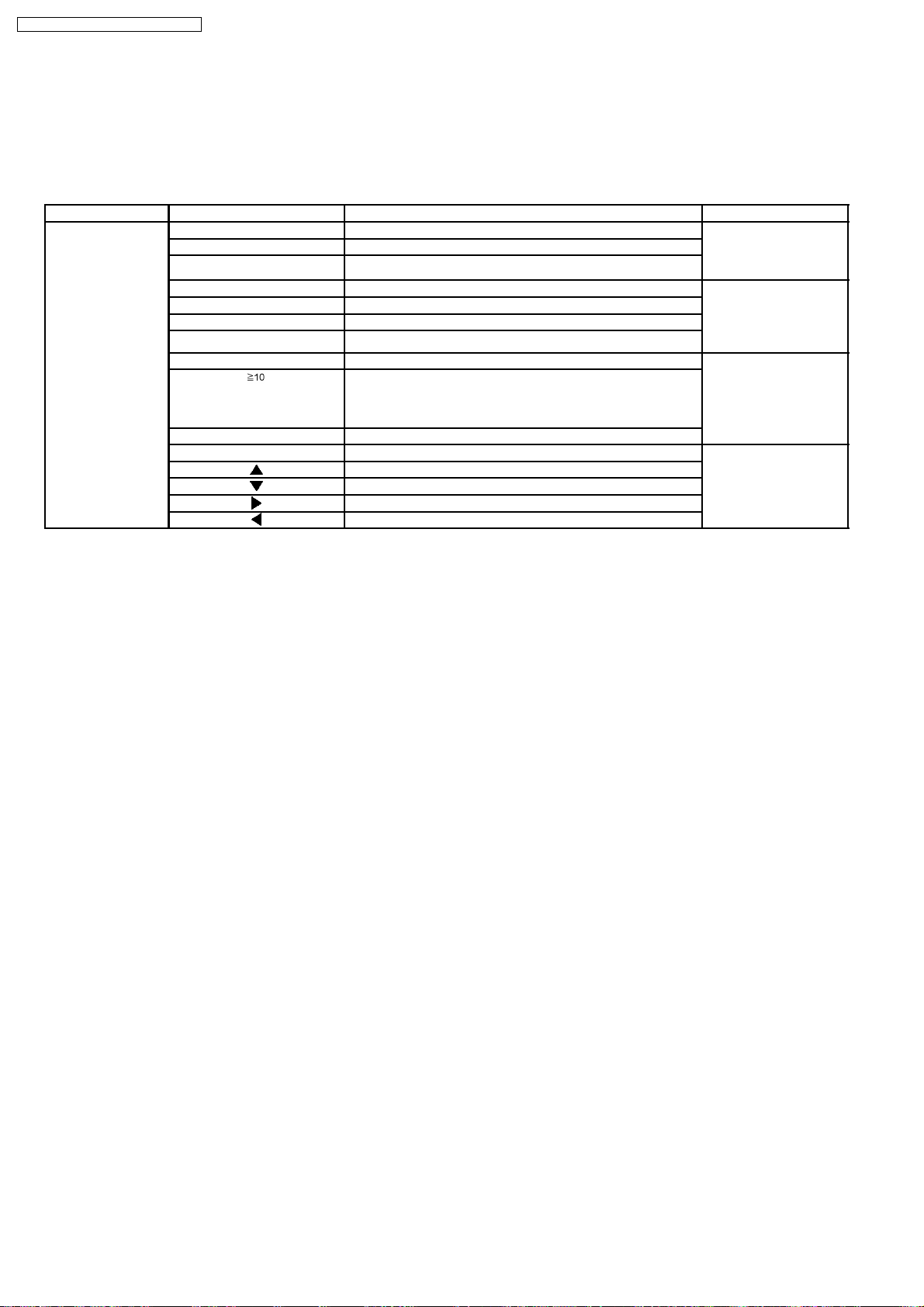
Main unit buttons Remote control unit buttons Application Note
[STOP] [0] Error code check. (Refer to the section
[5] Jitter checking.
[PAUSE] Initial setting of laser drive current.
[FUNCTIONS] DVD laser drive current check. (Refer to the section
[3] CD laser drive current check.
[6] Region display and mode.
[SOUND] CPPM/CRM keys check.
[7] Micro-processor firmware version check. (Refer to the section
[ ] Initialization of the player (factory setting is restored).
Used after replacement of Micro-processor (DV5 LSI) IC,
FLASH ROM IC (IC8651), EEPROM IC (IC8611) and DVD
Module P.C.B.
[OK] DVD Module P.C.B. reset.
[8] DVD Module P.C.B. firmware version check. (Refer to the section
[ ] Timer 1 check.
[ ] Timer 1 reset.
[ ] Timer 2 check.
[ ] Timer 2 reset.
“8.2.1. Service Mode
Table 1” for more
information.)
“8.2.2. Service Mode
Table 2” for more
information.)
“8.2.3. Service Mode
Table 3“ for more
information.)
“8.2.4. Service Mode
Table 4“ for more
information.)
Note:
An error code will be canceled if a power supply is turned OFF.
*1: CPPM is the copy guard function beforehand written in the disk for protection of copyrights.
*2: CEC is the consumer electronic control used for high-level user control of HDMI-connected devices.
*3: HDCP is the specification developed to control digital audio & video contents transmission for DVI or HDMI connections.
8.2. Service Mode Table
By pressing various button combinations on the main unit and remote control unit, you can activate the various service modes for
checking.
Special Note:
•
• Due to the limitations of the no. characters that can be shown on the FL Display, the “FL Display” button on the remote
• •
control unit can be used to show the two display pages. (Display 1 / Display 2).
•
• Refer to Section 7.1 for the section on “Remote Control Key Buttons Operations”.
• •
26
8.2.1. Service Mode Table 1
SA-PT860E / SA-PT860EB / SA-PT860EG
Error code
check
Jitter check
Item
DescriptionMode Name
Error code check
The latest error code stored in the
EEPROM IC is displayed.
Note: Refer to "Section 8.3 DVD Self
Diagnostic Function-Error Code" for
more detailed information on the error
codes.
Jitter check.
Jitter rate is measured and displayed.
Measurement is repeatedly done in
the cycle of one second. Read error
counter starts from zero upon mode
setting.
When target block data failed to be
read out, the counter advances by one
increment. When the failure is caused
by minor error, it may be corrected
when retried to enable successful
reading.
In this case, the counter advances by
one. When the error persists even
after retry, the counter may jump by
two or more.
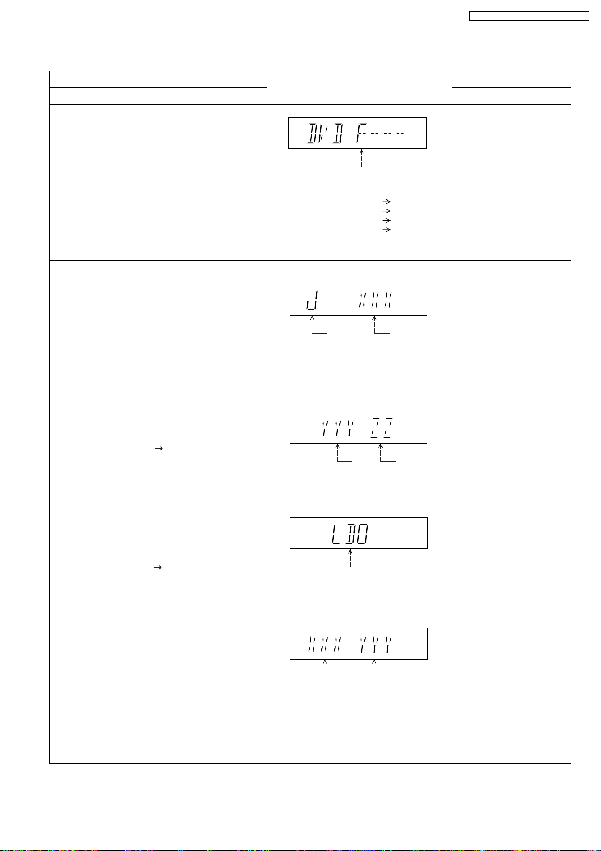
FL Display sequence:
Display 1 2.
FL Display
F / H / U
Error code (play_err) is expressed in the
following convention.
Error code = 0 x DAXX is expressed: DVDnn U12
Error code = 0 x DBXX is expressed: DVDnn H12
Error code = 0 x DXXX is expressed: DVDnn F123
Error code = 0 x 0000 is expressed: DVDnn F--* "xx" denotes the error code
(Display 1)
Jitter check
mode
Jitter rate is shown in decimal notation to one
place of decimal.
Focus drive value is shown in hexadecimal
notation.
(Display 2)
Lead
Error
Counter
Jitter rate
Focus Drive
Value
Key Operation
Front Key
In STOP (no disc) mode,
press [STOP] button on the
main unit, and [0] button on
the remote control unit. *With
pointing of cursor up and
down on display.
Cancelled automatically
5 seconds later.
To exit, press [POWER]
button on main unit or
remote control.
In STOP (with disc inside
tray) mode, press [STOP]
button on the main unit,
and [5] button on
the remote control unit,
after Display 1 appears,
then press [PLAY].
Press [POWER] or [STOP]
button to exit.
Press [FL Display] on
remote control unit for next
page (FL Display).
Initial setting of
laser drive
current
Initial setting of laser drive current.
Initial current value for the DVD laser
and CD laser is separately saved in
the EEPROM IC.
FL Display sequence:
Display 1 2.
(Display 1)
Laser current
measurement
mode
The value denotes the current in decimal
notation.
(Display 2)
CD
Laser
The above example shows the initial current
is XXXmA and YYYmA for CD laser and
DVD laser respectively when the laser is
switched on.
DVD Laser
In STOP (no disc) mode,
press [STOP] button on the
main unit, and [PAUSE]
button on the remote
control unit.
Cancelled automatically
5 seconds later.
Press [FL Display] on
remote control unit for next
page (FL Display) on values
of laser drive current.
27
SA-PT860E / SA-PT860EB / SA-PT860EG
8.2.2. Service Mode Table 2
DVD laser
drive current
measurement
CD laser drive
current
measurement
Item
DescriptionMode Name
DVD laser drive current measurement.
DVD laser drive current is measured
and the result is displayed together
with the initial value stored in the
EEPROM IC.
After the measurement, DVD laser
emission is kept on. It is turned off
when POWER key is switched off.
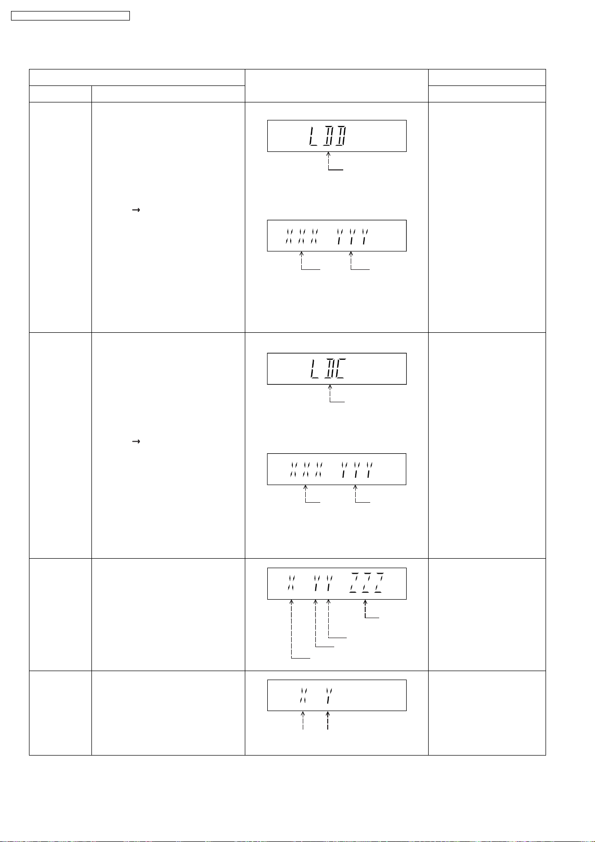
FL Display sequence:
Display 1 2.
CD laser drive current measurement.
CD laser drive current is measured
and the result is displayed together
with the initial value stored in the
EEPROM IC.
After the measurement, CD laser
emission is kept on. It is turned off
when POWER key is switched off.
FL Display sequence:
Display 1 2.
FL Display
(Display 1)
DVD laser current
measurement mode
The value denotes the current in decimal
notation.
(Display 2)
DVD
Laser
Initial Value
The above example shows the initial current
is XXXmA and the measured value is
YYYmA.
(Display 1)
The value denotes the current in decimal
notation.
(Display 2)
DVD
Laser
Value
CD laser current
measurement mode
Key Operation
Front Key
In STOP (no disc) mode,
press [STOP] button on the
main unit, and
[FUNCTIONS] button on
the remote control unit.
Cancelled automatically
5 seconds later.
Press [FL Display] on
remote control unit for next
page (FL Display) on values
of dvd drive current.
In STOP (no disc) mode,
press [STOP] button on
the main unit, and [3]
button on the remote
control unit.
Cancelled automatically
5 seconds later.
Press [FL Display] on
remote control unit for next
page. (FL Display)
Region display
CPPM/CRM
Keys Check
Region code display, TV broadcasting
system & the model no. information.
Note: Refer to Figure 8.1 for "Video
Design Information".
CPPM/CRM refers to the Content
Protection for Recordable Media and
Pre-Recorded Media. It displays the
existence of the keys as "1" or "0".
OK: Existing of keys.
NG: Non existing of keys.
CD
laser initial
value
The above example shows the initial current is
XXXmA and the measured value is YYYmA.
N: no PAL / P: PAL
Region No.: 0-8
0: NG
0: NG
1: OK
1: OK
CD laser
value
Model
No.
Information
N: NTSC / 6: PAL60
In STOP (no disc)
mode, press [STOP]
button on the main unit,
and [6] button on the
remote control unit.
Cancelled automatically
5 seconds later.
In STOP (no disc)
mode, press [STOP]
button on the main unit,
and [SOUND] button on
the remote control unit.
Cancelled automatically
5 seconds later.
28
SA-PT860E / SA-PT860EB / SA-PT860EG
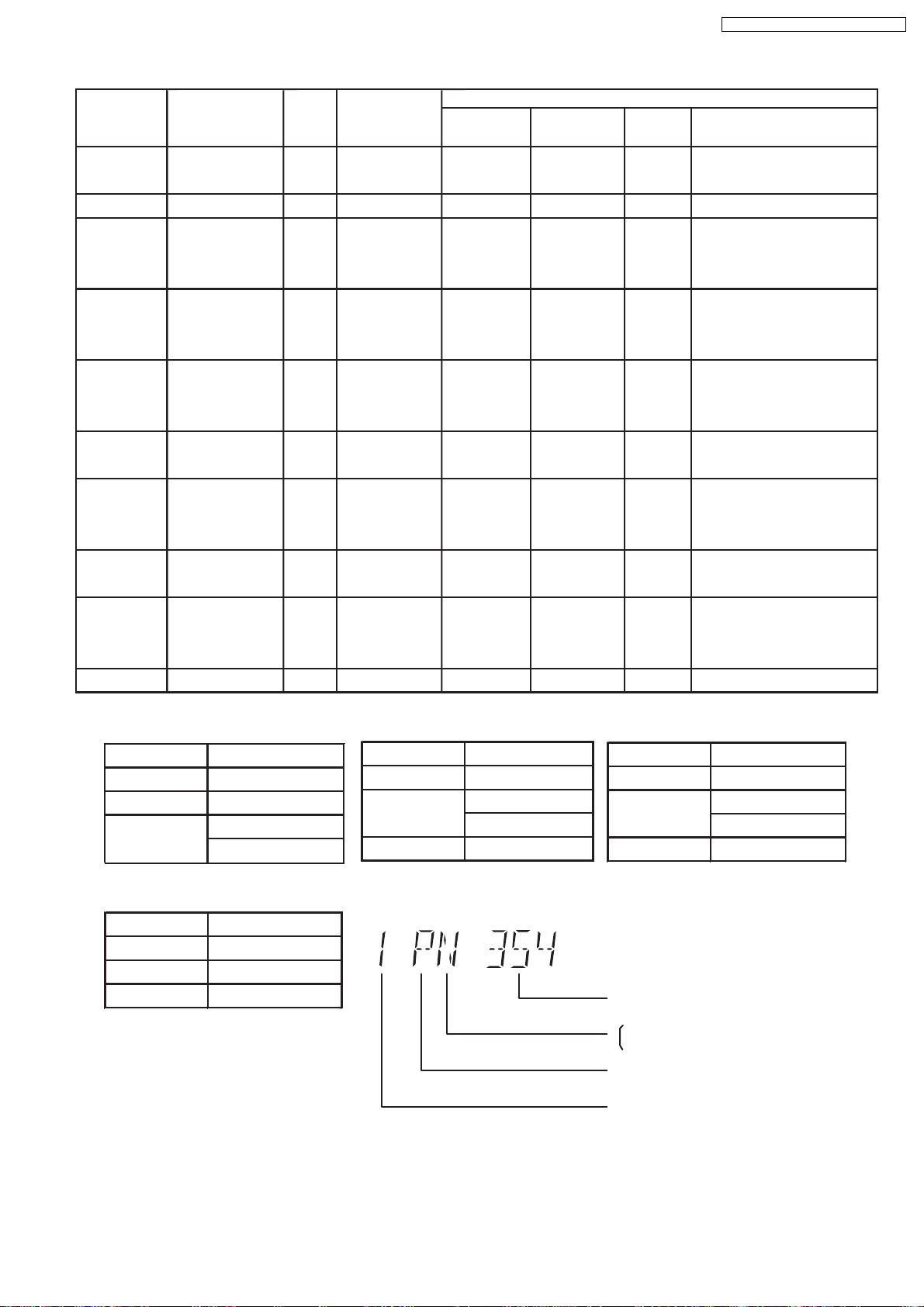
Product
OSD
Default
English
OSD Menu Language
English, Spanish,
Model Series
P, PC, PX
Country Region
USA, Canada, PX
Region
Code
1
TV Broadcasting
System
NTSC
Signal System
(Default)
NTSC (*A)
Region Display
(Default)
1PN
Canadian, French
(S) Japanese, English
Japan
2
NTSC
NTSC (*A)
2PN
Japanese
English, French, German,
E
Europe
2
PAL
PAL (*C)
2P6
English
Spanish, Polish, Russian,
Czech, Hungarian
English, French, German,
EB, EG
Europe
2
PAL
PAL (*C)
2P6
English
Italian, Spanish, Polish,
Swedish, Dutch
English, French, German,
GC, GS
Middle East
2
PAL
PAL (*C)
2P6
English
Spanish, Polish, Russian,
Czech, Hungarian
GCS, GD, English, Traditional Chinese
GT, GCT
GN
South East Asia,
Korea, Taiwan
New Zealand,
3
4
Australia
PL, GCP, LB
Central/South/
4
Latin America
PAL
NTSC
PAL
NTSC
NTSC (*B)
PAL (*C)
NTSC (*D)
3PN
4P6
4PN
English
English
English
English, French, German,
Italian, Spanish, Polish,
Swedish, Dutch
English, Spanish, French,
Brazilian Portuguese
English, French, German,
EE
CIS
5
SECAM
PAL (*C)
5P6
English
Spanish, Polish, Russian,
Czech, Hungarian
GK English, Simplified Chinese
China
6
PAL
NTSC (*B)
6PN
English
NTSC (*A)
Source Output
Screen Saver NTSC
NTSC disc NTSC
PAL disc
PAL (DVD-V)
NTSC (DVD-A/VCD)
NTSC (*D)
Source Output
Screen Saver NTSC
NTSC disc NTSC
PAL disc NTSC
NTSC (*B)
Source Output
Screen Saver NTSC
NTSC disc
NTSC (default)
PAL60
PAL disc PAL
Explanation of Display
Figure 8.1 Video Design Information
PAL (*C)
Source Output
Screen Saver PAL
NTSC disc
PAL60 (default)
NTSC
PAL disc PAL
Individual Model Code
N: If NTSC disc is played, NTSC output.
6: If NTSC disc is played, PAL60 output.
Can play PAL disc
Region code
29
SA-PT860E / SA-PT860EB / SA-PT860EG
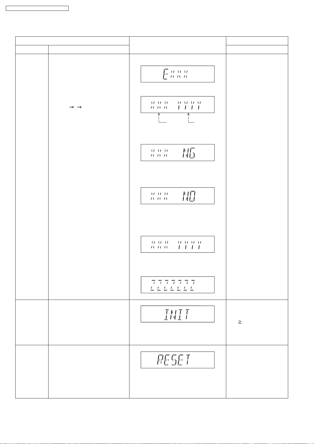
8.2.3. Service Mode Table 3
Micro-processor
firmware version
display &
EEPROM
checksum
display.
Item
DescriptionModel Name
Micro-processor firmware version
display & EEPROM checksum display.
EEPROM checksum is only available
due to existence of EEPROM IC.
Note: Condition 1/2/3 shows the state
of EEPROM IC.
FL Display sequence:
Display 1 2 3.
FL Display
(Display 1)
(Display 2)
Opecon
Version
(Condition 1)
If the version of the EEPROM does not match,
[NG] is displayed.
(Condition 2)
EEPROM
Checksum
(If applicable,
refer below.)
Key Operation
Front Key
In STOP (no disc)
mode, press [STOP]
button on the main unit,
and [7] button on the
remote control unit.
Cancelled automatically
5 seconds later.
Initialization
DVD
Module P.C.B.
Reset
Initialization.
User settings are cancelled and player
is initialized to factory setting.
It is necessary when after replacement
of Micro-processor (DV5 LSI) IC,
FLASH ROM IC (IC8651), EEPROM
IC (IC8611) & DVD Module P.C.B.
To reset DVD Module P.C.B.
This process is used when the DVD
Module P.C.B. or FLASH ROM
IC is replaced with a new one.
(a) If there is NO EEPROM header string
OR
(b) If there is no EEPROM (no data is received
by Micro-processor), [NO] is displayed.
(Condition 3)
If the EEPROM version matches, checksum
[YYYY] is displayed.
(Display 3)
Press [FL Display] button on
remote control unit for next
page. (FL Display)
In STOP (no disc)
mode, press [STOP]
button on the main unit,
and [ 10] button on the
remote control unit.
Cancelled automatically
5 seconds later.
While in initialization
mode, press & hold
[STOP] button on the main
unit for 3 seconds, follow
by [OK] button on the
remote control unit.
Cancelled automatically
5 seconds later.
30
 Loading...