

Panasonic SAHT-40-EE Service manual
Specification
nAMPLIFIER SECTION
RMS output power of each channel driven
10% total harmonic distortion
1 kHz front CH
90 W per channel (4 Ω)
1 kHz surround CH
90 W per channel (4 Ω)
1 kHz center CH
220 W per channel (6 Ω)
100 Hz subwoofer CH
220 W per channel (6 Ω)
Total RMS output power 800 W
Rated minimum sine wave RMS power output
1% total harmonic distortion (Dolby Digital mode)
1 kHz front CH
50 W per channel (4 Ω)
1 kHz surround CH
50 W per channel (4 Ω)
1 kHz center CH
150 W per channel (6 Ω)
100 Hz subwoofer CH
150 W per channel (6 Ω)
Total RMS output power 500 W
Total harmonic distortion
Half power at 1 kHz (Front CH) 0.5% (4 Ω)
Input sensitivity
GAME/AUX, TV, DVR/DVD-P 450 mV, IHF’66
MUSIC PORT 250 mV, IHF’66
S/N at rated power (4 ΩΩΩΩ)
GAME/AUX, TV, DVR/DVD-P 80 dB, (85 dB, IHF’66)
ORDER NO. MD0604121C3
Home Theater Audio System
SA-HT40EE
Colour
(S).......................Silver Type
MUSIC PORT
Input impedance
GAME/AUX, TV, DVR/DVD-P, MUSIC PORT
Tone controls
BASS 50 Hz, +10 to -10 dB
TREBLE 20kHz,+10to-10dB
Digital input
OPTICAL
COAXIAL
nFM TUNER SECTION
Frequency range
Sensitivity
S/N 30 dB 1.9 µV/75 Ω
S/N 26 dB 1.8 µV/75 Ω
S/N 20 dB 1.6 µV/75 Ω
IHF usable sensitivity (IHF’58) 2.2 µV/75 Ω
IHF 46 dB stereo quieting sensitivity
Total Harmonic distortion
MONO 0.2%
STEREO
S/N
MONO 60 dB (71 dB, IHF)
STEREO 58 dB (65 dB, IHF)
Frequency response
Image rejection at 98 MHz 40 dB
IF rejection at 98 MHz 70 dB
Stereo separation (1 kHz) 40 dB
70 dB, (85 dB, IHF’66)
47 kΩ
87.50 MHz to 108.00 MHz
22 µV/75 Ω
0.3%
20 Hz to 15 kHz, +1 dB, -2 dB
2
1
© 2006 Matsushita Electric Industrial Co. Ltd.. All
rights reserved. Unauthorized copying and
distribution is a violation of law.
SA-HT40EE
Antenna terminal 75 Ω (unbalanced)
nAM TUNER SECTION
Frequency range
522 kHz to 1611 kHz (9 kHz steps)
530 kHz to 1620 kHz (10 kHz steps)
Sensitivity 500 µV/m
Selectivity (at 999 kHz) 30 dB
nGENERAL
Power supply
AC 230 to 240 V, 50 Hz
Power consumption
Dimensions (W × H × D)
430 mm x 105 mm x 385 mm
Mass 3.8 kg
Power consumption in standby mode: 1W
nSYSTEM
120 W
System: SC-HT40 (EE)
Main unit: SA-HT40 (EE)
Front speakers: SB-PF41 (GN)
Surround speakers: SB-PS41 (GN)
Center speaker: SB-PC40 (P)
Subwoofer: SB-W 40 (P)
Notes:
1. Specifications are subject to change without notice.
Mass and dimensions are approximate.
2. Total harmonic distortion is measured by the digital spectrum
analyzer.
* Manufactured under license from Dolby Laboratories.
“Dolby”, “Pro Logic” and the double-D symbol are trademarks of
Dolby Laboratories.
** Manufactured under license from Digital Theater System.
“DTS” and “DTS Digital Surround” are trademarks of Digital Theater
System.
CONTENTS
Page Page
1 Safety Precautions 4
1.1. General Guidelines
1.2. Before Repair and Adjustment
1.3. Protection Circuitry
2 Prevention of Electro Static Discharge (ESD) to
Electrostatically Sensitive (ES) Devices
3 Handling the Lead Solder
3.1. About Lead Free Solder (PbF)
4 Accessories
5 Operation Procedures
5.1. Remote Control Operation
5.2. Main Unit Operation
6 New Features
6.1. Music Port
7 Self Diagnosis and Special Mode Setting
7.1. Doctor & Service Mode (Special Mode setting)
7.2. Error Code Table
8 Assembling and Disassembling
8.1. Caution
8.2. Disassembly Flow Chart
8.3. Main Parts Location
8.4. Disassembly of Top Cabinet
8.5. Disassembly of Rear Panel
8.6. Disassembly of Front Panel
8.7. Disassembly of Panel P.C.B., Music Port P.C.B. & Volume
P.C.B.
8.8. Disassembly of Main P.C.B.
8.9. Disassembly of DSP P.C.B.
8.10. Disassembly of AC In P.C.B.
10
10
11
11
12
13
13
13
14
15
15
16
16
17
18
18
4
4
4
5
5
5
6
7
7
8
8.11. Disassembly of Power P.C.B.
8.12. Disassembly of Digital Amp P.C.B.
9 Service Position
9.1. Checking the DSP P.C.B. (Side A) & AC In P.C.B.
9.2. Checking the DSP P.C.B. (Side B)
9.3. Checking the Panel P.C.B., Music Port P.C.B. and Volume
P.C.B.
9.4. Checking the Main P.C.B., Power P.C.B. & Digital Amp
P.C.B.
10 Voltage Measurement and Waveform Chart
10.1. Voltage Measurement
10.2. Waveform Chart
11 Wiring Diagrams
12 Block Diagram
13 Schematic Diagram
13.1. Notes of Schematic Diagram
13.2. (A) DSP Circuit
13.3. (B) Main Circuit
13.4. (C) Digital Amp Circuit
13.5. (D) Panel Circuit, (E) Volume Circuit & (F) Music Port
Circuit
13.6. (G) Power Circuit & (H) AC In Circuit
14 Printed Circuit Board Diagram
14.1. (A) DSP P.C.B.
14.2. (B) Main P.C.B.
14.3. (C) Digital Amp P.C.B.
14.4. (D) Panel P.C.B., (E) Volume P.C.B. & (F) Music Port
P.C.B.
14.5. (G) Power P.C.B.
19
20
22
22
22
23
24
25
25
29
33
35
37
37
39
41
45
47
49
51
52
53
54
55
56
2

SA-HT40EE
14.6. (H) AC In P.C.B. 57
15 Illustration s of IC's, Transistors & Diodes
16 Terminal Functions of Integrated Circuits
16.1. IC301 (C2CBYY0 00152): Microprocessor
17 Exploded Views
59
60
60
17.1. Cabinet Parts Location
17.2. Packaging
18 Replacement Parts List
61
61
62
63
3
SA-HT40EE
1 Safety Precautions
1.1. General Guidelines
1. When servicing, observe the original lead dress. If a short circuit is found, replace all parts which have been overheated or
damaged by the short circuit.
2. After servicing, see to it that all the protective devices such as insulation barriers, insulation papers shields are properly
installed.
3. After servicing, make the following leakage current checks to prevent the customer from being exposed to shock hazards.
1.1.1. Leakage Current Cold Check
1. Unplug the AC cord and connect a jumper between the two prongs on the plug.
2. Measure the resistance value, with an ohmmeter, between the jumpered AC plug and each exposed metallic cabinet part on
the equipment such as screwheads, connectors, control shafts, etc. When the exposed metallic part has a return path to the
chassis, the reading should be between 1MΩ and 5.2Ω.
When the exposed metal does not have a return path to the chassis, the reading must be
.
Fig. 1
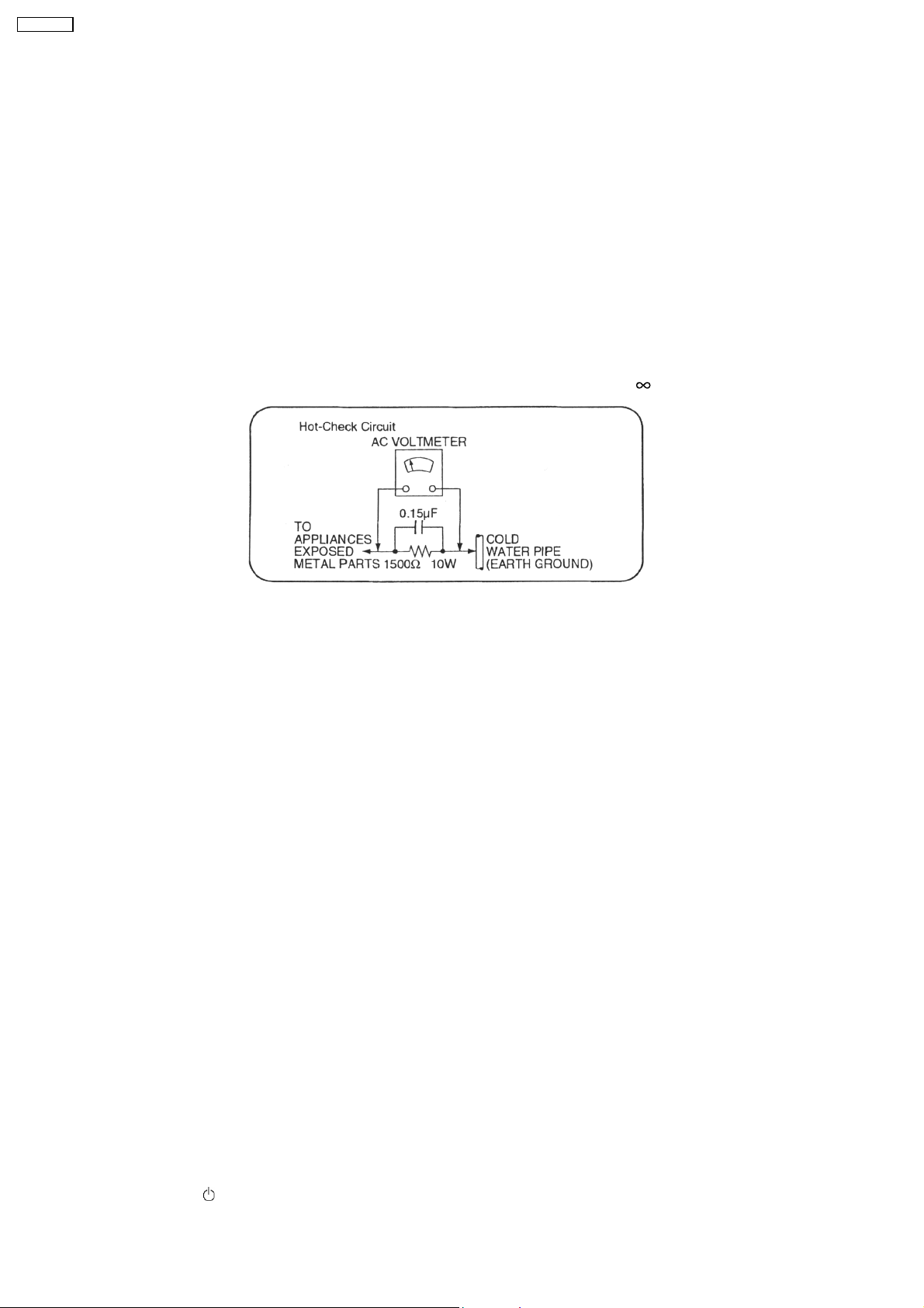
1.1.2. Leakage Current Hot Check (See Figure 1.)
1. Plug the AC cord directly into the AC outlet. Do not use an isolation transformer for this check.
2. Connect a 1.5kΩ, 10 watts resistor, in parallel with a 0.15µF capacitors, between each exposed metallic part on the set and a
good earth ground such as a water pipe, as shown in Figure 1.
3. Use an AC voltmeter, with 1000 ohms/volt or more sensitivity, to measure the potential across the resistor.
4. Check each exposed metallic part, and measure the voltage at each point.
5. Reverse the AC plug in the AC outlet and repeat each of the above measurements.
6. The potential at any point should not exceed 0.75 volts RMS. A leakage current tester (Simpson Model 229 or equivalent) may
be used to make the hot checks, leakage current must not exceed 1/2 milliamp. In case a measurement is outside of the limits
specified, there is a possibility of a shock hazard, and the equipment should be repaired and rechecked before it is returned to
the customer.
1.2. Before Repair and Adjustment
Disconnect AC power, discharge Power Supply Capacitors C707 & C1706 through a 10 Ω, 1W resistor to ground.
DO NOT SHORT-CIRCUIT DIRECTLY (with a screwdriver blade, for instance), as this may destroy solid state devices.
After repairs are completed, restore power gradually using a variac, to avoid overcurrent.
Current consumption at AC 230 V - 240 V, 50Hz in NO SIGNAL mode should be 200 ~ 800 mA.
1.3. Protection Circuitry
The protection circuitry may have operated if either of the following conditions is noticed:
*No sound is heard when the power is supplied.
*Sound stops during a performance.
The functions of this circuitry is to prevent circuitry damage, for example, the positive and negative speaker connection wires are
“shorted”, or if speaker systems with an impedance less than the indicated rated impedance of this unit are used.
If this occurs, follow the procedure outlined below:
1. Press the STANDBY
/ON button, switch to STANDBY mode.
4
SA-HT40EE
2. Determine the cause of the problem and correct it.
3. Press the STANDBY
Note:
When the protection circuitry functions, the unit will not operate unless the STANDBY
and then ON again.
/ON button once again, supply the power.
/ON button is first switched STANDBY
2 Prevention of Electro Static Discharge (ESD) to
Electrostatically Sensitive (ES) Devices
Some semiconductor (solid state) devices can be damaged easily by electricity. Such components commonly are called
Electrostatically Sensitive (ES) Devices. Examples of typical ES devices are integrated circuits and some field-effect transistors and
semiconductor “chip” components. The following techniques should be used to help reduce the inciden ce of component damage
caused by electro static discharge (ESD).
1. Immediately before handling any semiconductor component or semiconductor-equiped assembly, drain off any ESD on your
body by touching a known earth ground. Alternatively, obtain and wear a commercially available discharging ESD wrist strap,
which should be removed for potential shock reasons prior to applying power to the unit under test.
2. After removing an electrical assembly equiped with ES devices, place the assembly on a conductive surface such as aluminium
foil, to prevent electrostatic charge build up or exposure of the assembly.
3. Use only a grounded-tip soldering iron to solder or unsolder ES devices.
4. Use only an anti-static solder remover device. Some solder removal devices not classified as “anti-static (ESD protected)” can
generate electrical charge to damage ES devices.
5. Do not use freon-propelle d chemicals. These can generate electrical charges sufficient to damage ES devices.
6. Do not remove a replacement ES device from its protective package until immediately before you are ready to install it. (Most
replacement ES devices are packaged with leads electrically shorted together by conductive foam, aluminium foil or
comparable conductive material).
7. Immediately before removing the protective material from the leads of a replacement ES device, touch the protective material
to the chassis or circuit assembly into which the device will be installed.
Caution
Be sure no power is applied to the chassis or circuit, and observe all other safety precautions.
8. Minimize body motions when handling unpackaged replacement ES devices. (Otherwise harmless motion such as the brushing
together of your clothes fabric or the lifting of your foot from a carpeted floor can generate static electricity (ESD) sufficient to
damage an ES device).
3 Handling the Lead Solder
3.1. About Lead Free Solder (PbF)
Distinction of PbF P.C.B. :
P.C.B.s (manufactured) using lead free solder will have a PbF stamp on the P.C.B.
Caution:
· Pb free solder has a higher melting point that standard solder; Typically the melting point is 50 - 70°F (30 - 40°C) higher.
Please use a high temperature soldering iron. In case of the soldering iron with temperature control, please set it to 700 ± 20°F
(370 ± 10°C).
· Pb free solder will tend to splash when heated too high (about 1100°F/600°C).
· W hen soldering or unsoldering, please completely remove all of the solder on the pins or solder area, and be sure to heat the
soldering points with the Pb free solder until it melts enough.
5
SA-HT40EE
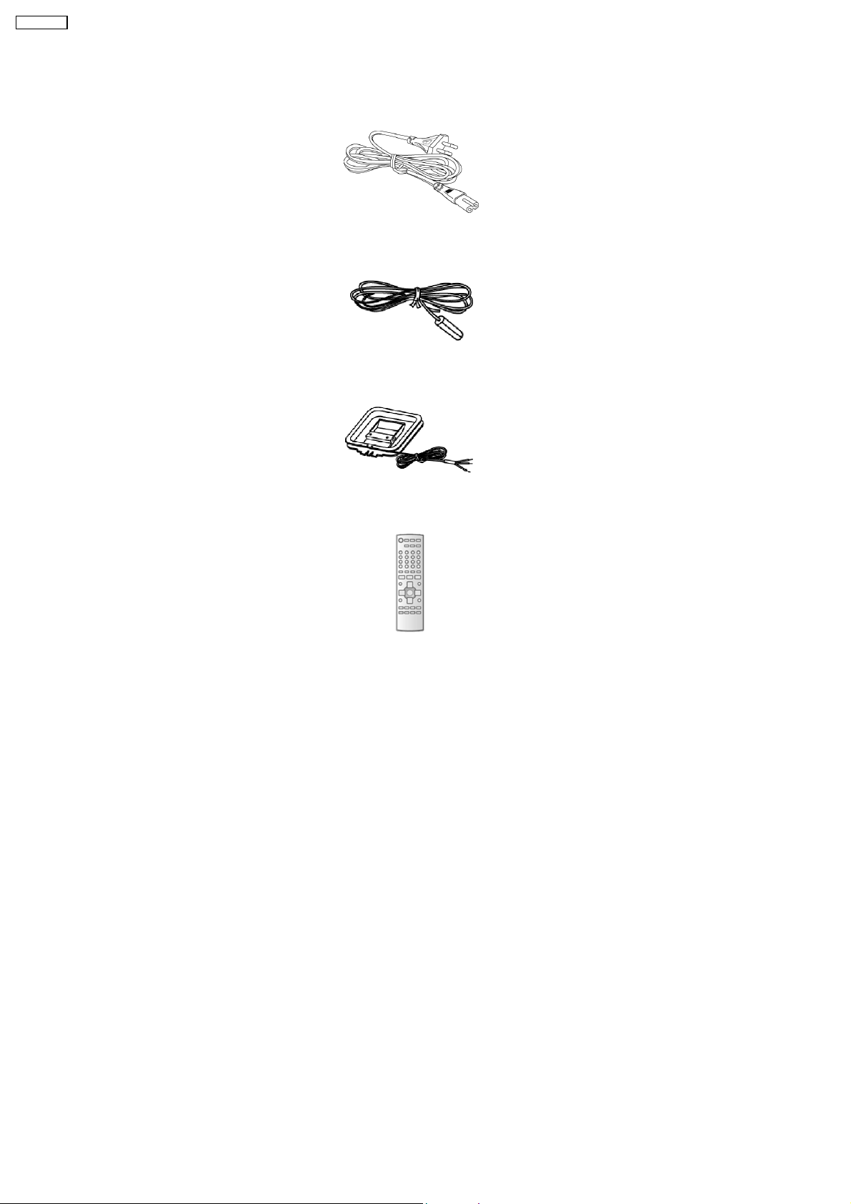
4 Accessories
Note: Refer to Packing Materials & Accessories (Section 18) for part number.
AC power cord
FM indoor antenna
AM loop antenna
Remote control
6
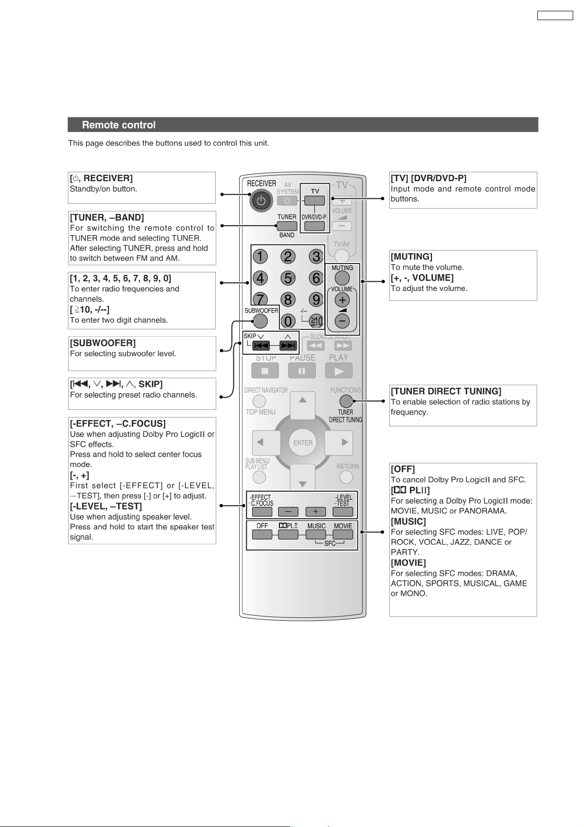
5 Operation Procedures
5.1. Remote Control Operation
SA-HT40EE
7
SA-HT40EE
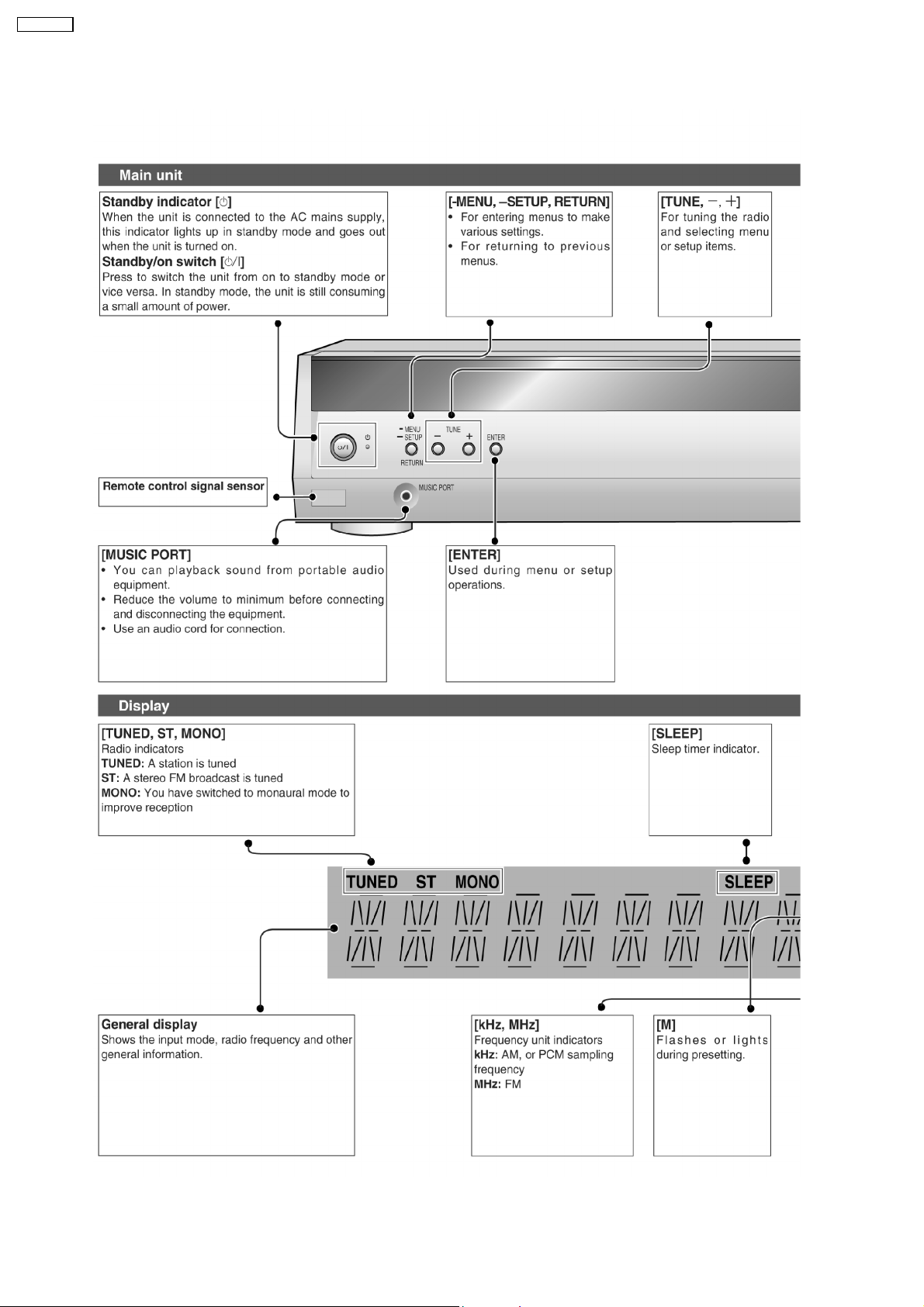
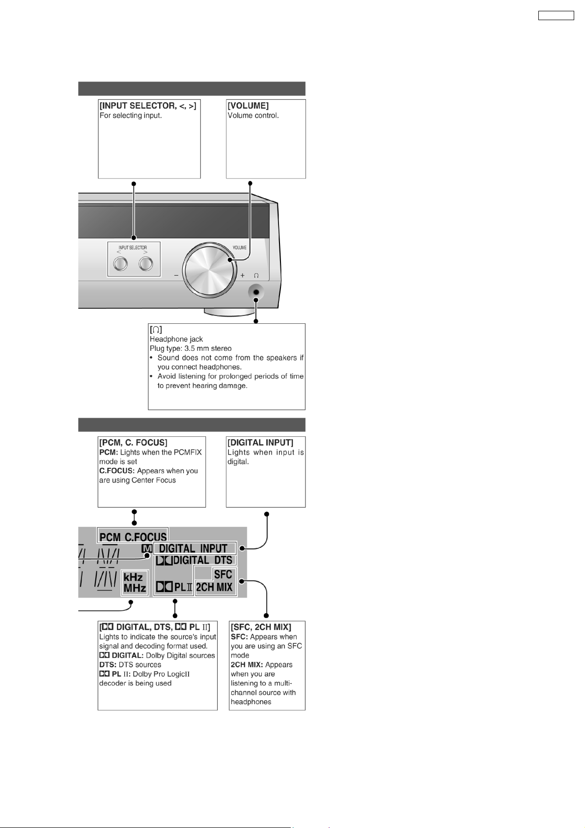
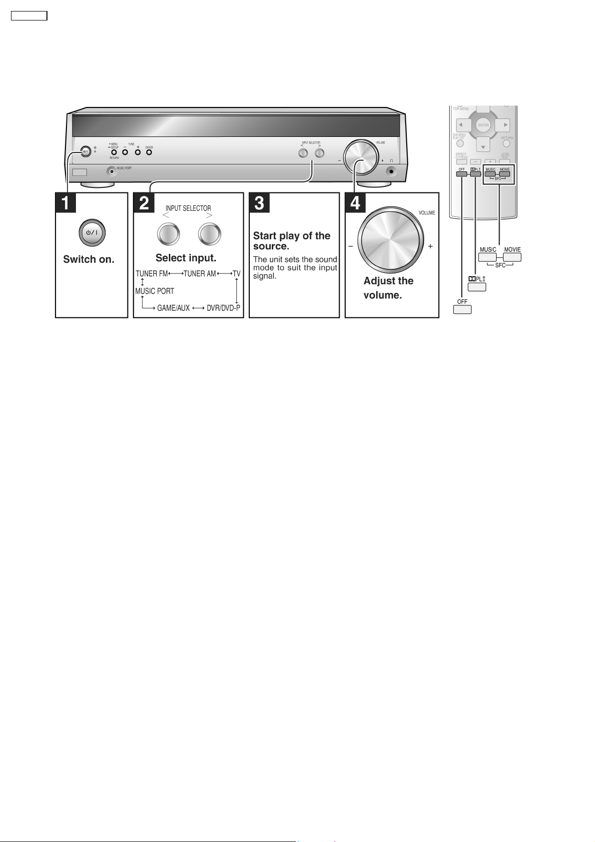
5.2. Main Unit Operation
8
SA-HT40EE
9
SA-HT40EE
6 New Features
6.1. Music Port
10
7 Self Diagnosis and Special Mode Setting
This unit is equipped with function for checking and inspecting namely : Self-Diagnostic and Test Mode.
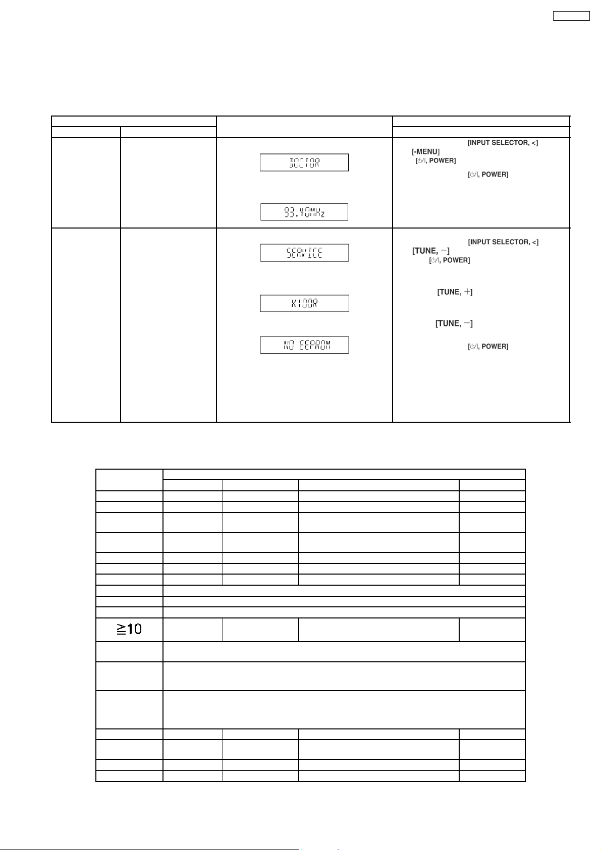
7.1. Doctor & Service Mode (Special Mode setting)
Item FL Display Key Operation
Mode Name Description Front Key
Doctor Mode To enter into Doctor Mode
for checking of various
items. (For more
information, refer to
section 7.1.1.)
1. FL will display as below for 3s:
2. Initialization of all settings & the tuner
frequency is set as below.
1. Press & hold and
button on main unit follow by the
To exit, press the
main unit or remote control.
SA-HT40EE
button at the same time.
button on the
Service Mode To enter into Service
Mode for checking of uP
software Version and
displaying EEPROM
checksum.
1. FL will display as below:
2. Next is the micro-processor firmware version
no.
3. This is follow by checking of EEPROM:-
Notes:
1. When NO EEPROM, it will display “NO
EEPROM”.
2. When there is EEPROM, it will display
“SUM****” whereby **** refers to check sum
no. (ROM Correction).
For Service mode:
1. Press & hold
the
To check uP software Version:
1. Press
To check EEPROM:
1. Press
To exit, press the
main unit or remote control.
button on main unit follow by
button at the same time.
button on main unit.
button on main unit.
7.1.1. Inspection & Checking Items
After entering into doctor mode, the main unit can be used for checking of various items using the remote control.
Remote Control Test Mode Function and settings
Selector Sound Mode Other setting Vol/Tone
CH 1 TV STEREO Analog -18dB/0dB
CH 2 DVR/DVD-P STEREO Analog -18dB/0dB
CH 3 REAR MUSIC
PORT
CH 4 FRONT MUSIC
PORT
CH 5 TV STEREO Digital (OPT 1) -48dB/0dB
CH 6 DVR/DVD-P STEREO Digital (OPT 2) -48dB/0dB
CH 7 TV STEREO Digital (COAX) -48dB/0dB
CH 8 If the input selector is TUNER, auto tuning function is started to upward on current frequency.
CH 9 If the input selector is TUNER, auto tuning function is started to downward on current frequency.
CH 0 If the input selector is TUNER in E2 mode, Display Mode (PS/PTY) is changed.
TUNER STEREO Frequency: FM max
MUTING All indicators of FL are displayed. All LED are off.
Note: After this setting, only ‘POWER’ button by the remote control can be entered.
Volume Up Check Main uP software Version.
Display [K 100R ** ]; **is current version.
* Volume is still increased but not displayed.
Volume Down Check for EEPROM & Check Sum.
Display [SUM ****]; **** is checksum.
If no ROM correction, and when EEPROM is not attach, display [NO_EEPROM]
* Volume is still reduced but not displayed.
SUBW DVR/DVD-P ---------- All CH printed out -18dB/0dB
LEVEL No change SURROUND Scan the test noise output channel with
-/L TV STEREO Balance is set to leftmost. -18dB/0dB
+/R TV STEREO Balance is set to rightmost -18dB/0dB
STEREO Analog -18dB/0dB
STEREO Analog -18dB/0dB
-48dB/0dB
FM Mode: MONO
-18dB/0dB
500ms intervals.
and
button on
11
SA-HT40EE
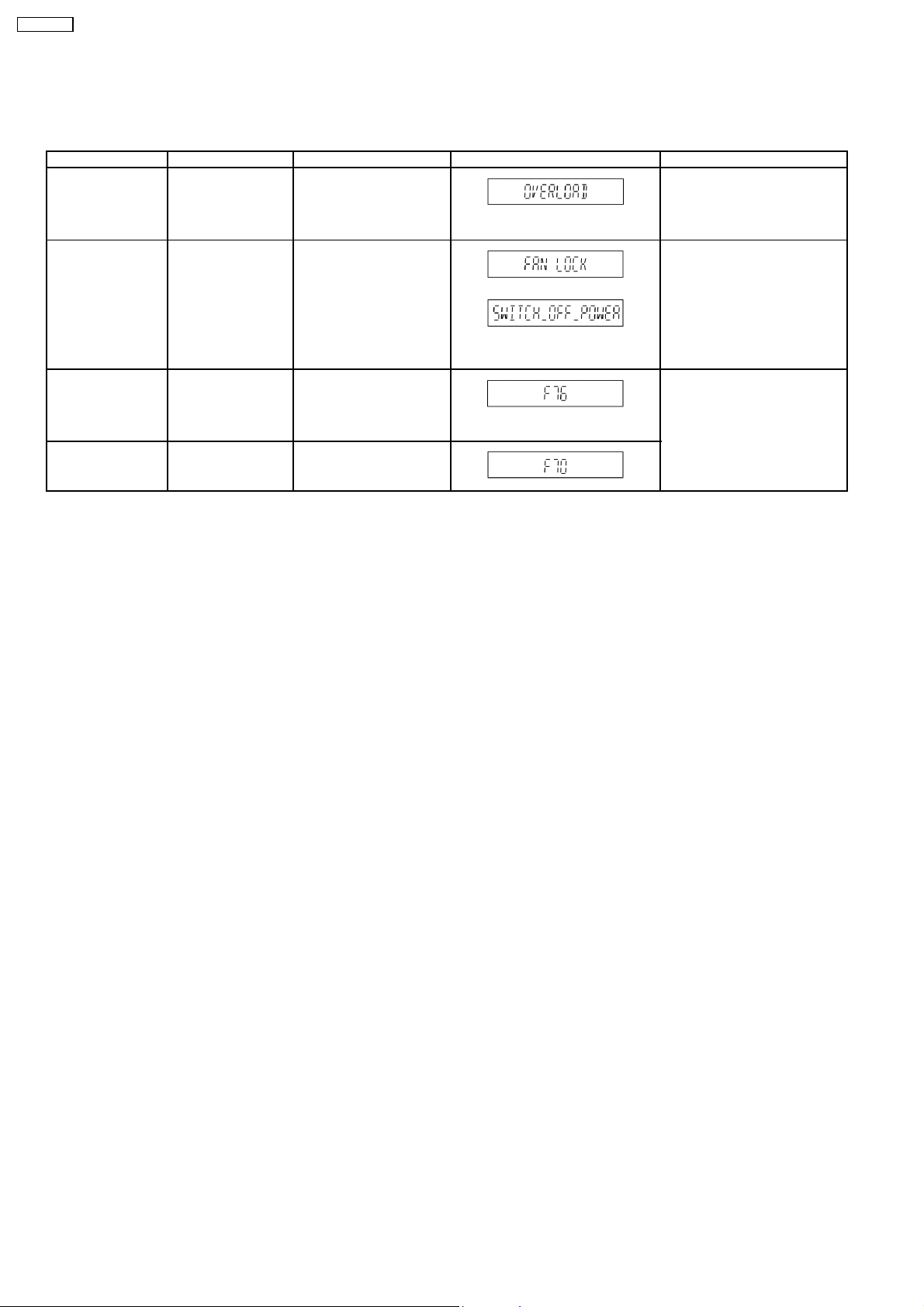
7.2. Error Code Table
Self- Diagnosis Function provides information on any problems occuring for the units and its respective parts by display ing error
codes.
Error Code Diagnosis Contents Description of error Automatic FL Display Remarks
OVERLOAD Speaker short, power
amplifier failure
Digital amplifier
abnormal operation
FAN LOCK Detection of FAN
LOCK
F76 Detection of POWER
MALFUNCTION &
abnormal operation
F70 Detection of POWER
MALFUNCTION &
abnormal operation
Both [SHORT_DET] &
[FAN_LOCK] signal is
detected as active high
while [DC_DET] signal is
active low.
Both [SHORT_DET] &
[DC_DET] signal is
detected as active high
while [FAN_LOCK] signal is
active low.
Both [FAN_LOCK] &
[DC_DET] signal is
detected as active high
while [SHORT_DET] is
active low.
All channels into muting.
* When any button is next press
when in this condition.
12
SA-HT40EE
8 Assembling and Disassembling
8.1. Caution
“Attention Servicer”
Some chassis components may have sharp edges. Be careful when disassembling and servicing.
1. This section describes procedures for checking the operation of the major printed circuit boards and replacing the main
components.
2. For reassembly after operation checks or replacement, reverse the respective procedures.
Special reassembly procedures are described only when required.
3. Select items from the following index when checks or replacement are required.
4. Refer to the Parts No. on the page of “Replacement Parts List” (Section 18), if necessary.
Below is the list of disassembly procedures
· Disasse mbly of Top Cabinet
· Disasse mbly of Rear Panel
· Disasse mbly of Front Panel
· Disasse mbly of Panel P.C.B., Music Port P.C.B. & Volume P.C.B.
· Disasse mbly of Main P.C.B.
· Disasse mbly of DSP P.C.B.
· Disasse mbly of AC In P.C.B.
· Disasse mbly of Power P.C.B.
· Disasse mbly of Digital Amp P.C.B.
Caution
Do ensure the correct screw is uses.
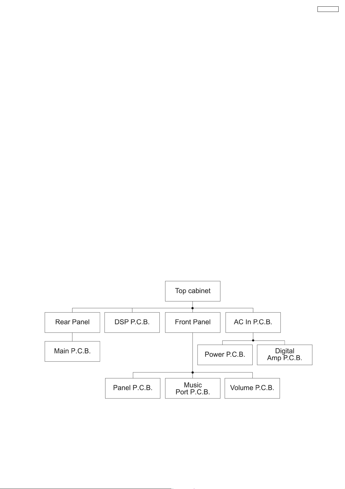
8.2. Disassembly Flow Chart
The following chart is the procedure for disassembling the casing and inside parts for internal inspection when carrying out the
servicing.
To assemble the unit, reverse the steps shown in the chart as below.
13
SA-HT40EE
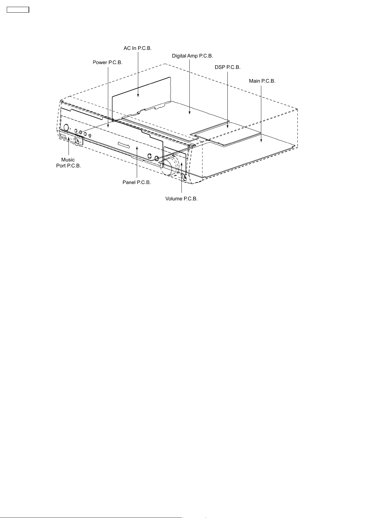
8.3. Main Parts Location
14
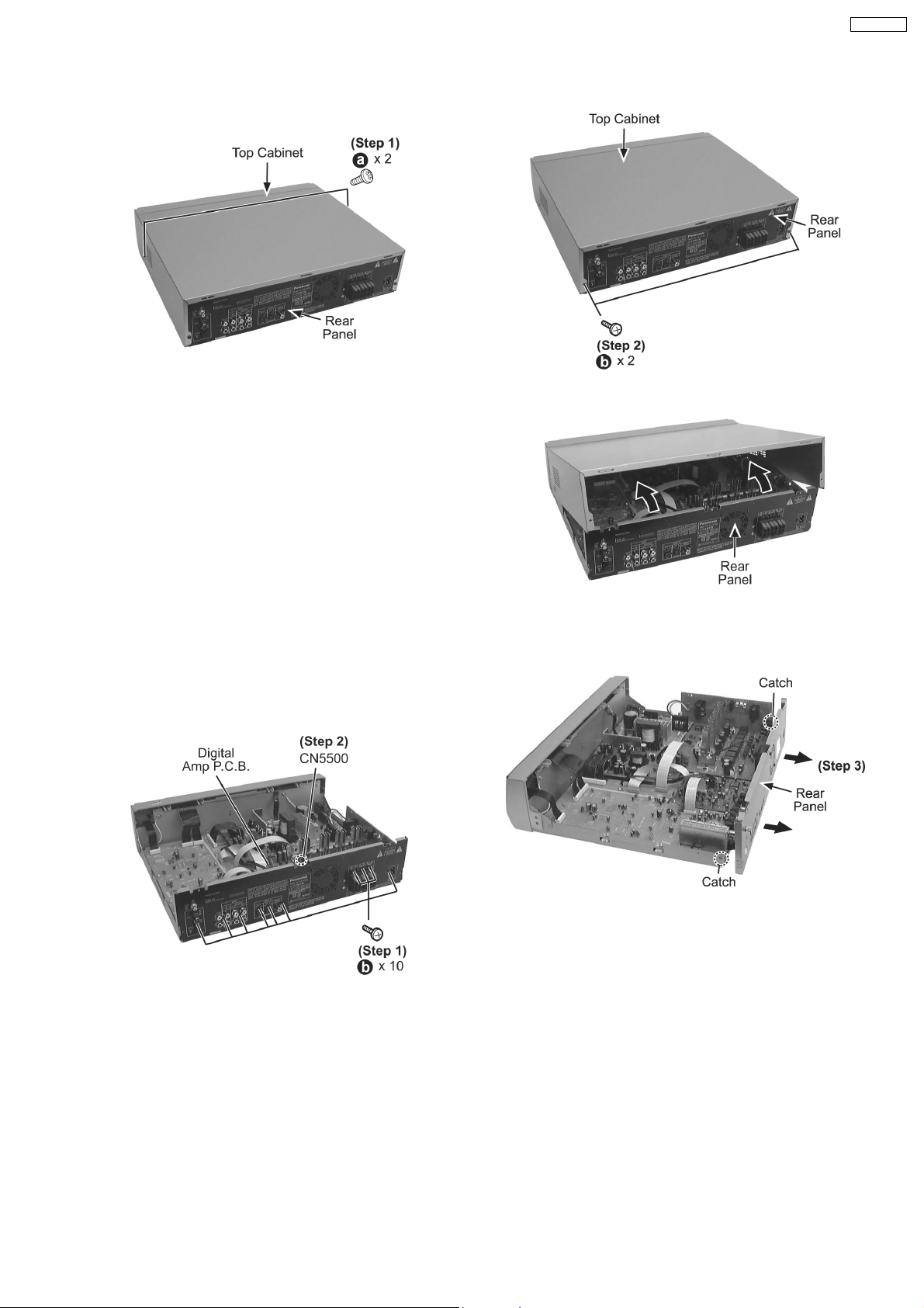
8.4. Disassembly of Top Cabinet
Step 1: Remove 2 screws.
Step 2 : Remove 2 screws at rear panel.
SA-HT40EE
Step 3 : Open and lift up the top cabine t as arrow shown.
8.5. Disassembly of Rear Panel
· Follow the (Step 1) - (Step 3) of item 8.4. - Disassembly of Top Cabinet
Step 1 : Remove 10 screws at rear panel.
Step 2 : Detach wire connector (CN5500) at Digital Amp
P.C.B..
Step 3 : Release 2 catches and pull the rear panel backwards
as the arrow shown.
15
SA-HT40EE
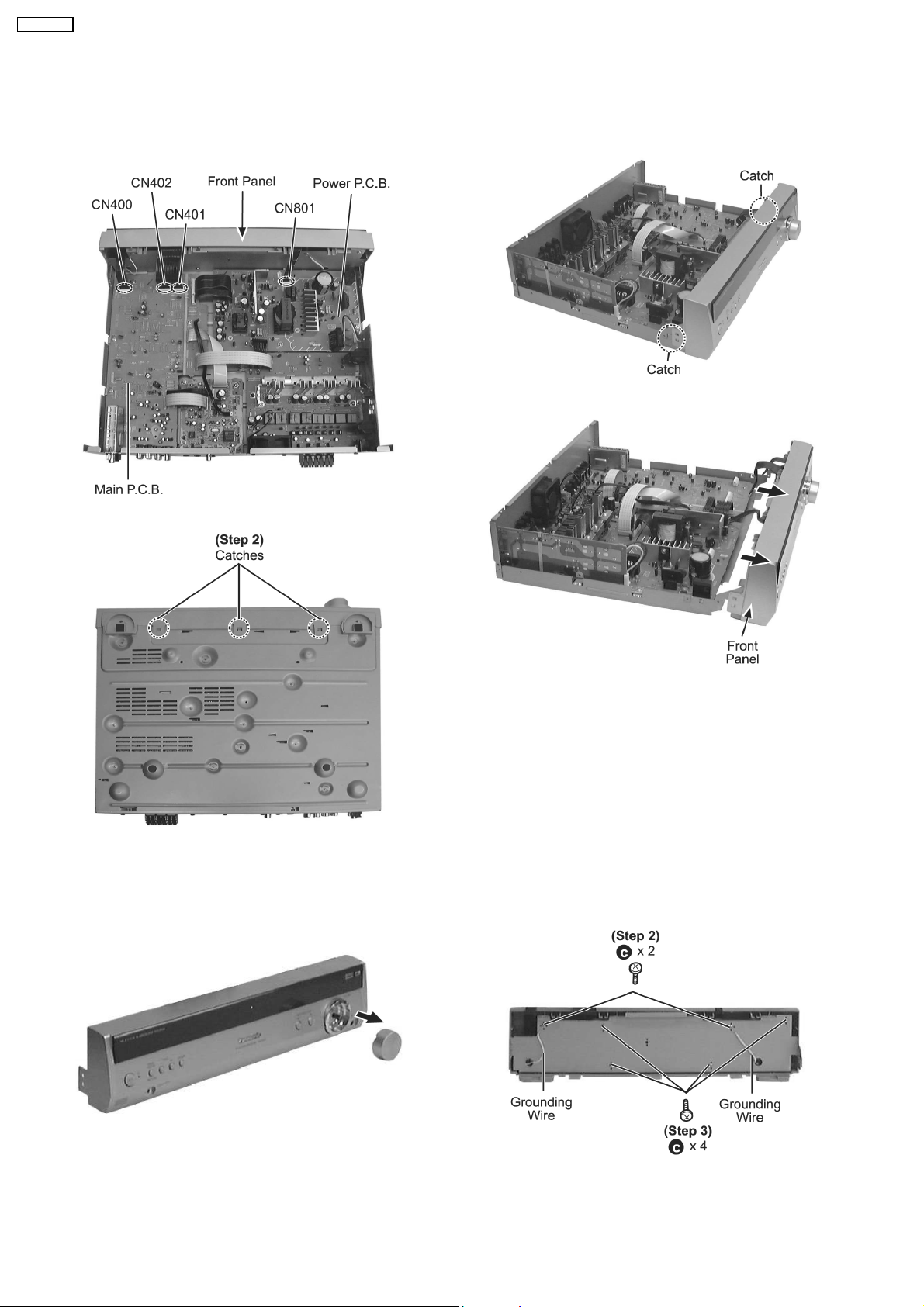
8.6. Disassembly of Front Panel
· Follow the (Step 1) - (Step 3) of item 8.4. - Disassembly of Top Cabinet
Step 1 : Detach the wire connections (CN400, CN402 &
CN401) at Main P.C.B. and (CN801) at Power P.C.B..
Step 3 : Releas e 2 catches.
Step 4 : Push forward front panel as the arrow shown.
Step 2 : Releas e 3 catches.
8.7. Disassembly of Panel P.C.B., Music Port P.C.B. & Volume P.C.B.
· Follow the (Step 1) - (Step 3) of item 8.4. - Disassembly of Top Cabinet
· Follow the (Step 1) - (Step 4) of item 8.6. - Disassembly of Front Panel
Step 1 : Remove the volume knob as picture shown.
Step 2 : Remove 2 screws grounding wires as picture shown.
Caution:
Remember to screw the 2 grounding wires during assembly.
Step 3 : Remove 4 screws as picture shown.
16
SA-HT40EE
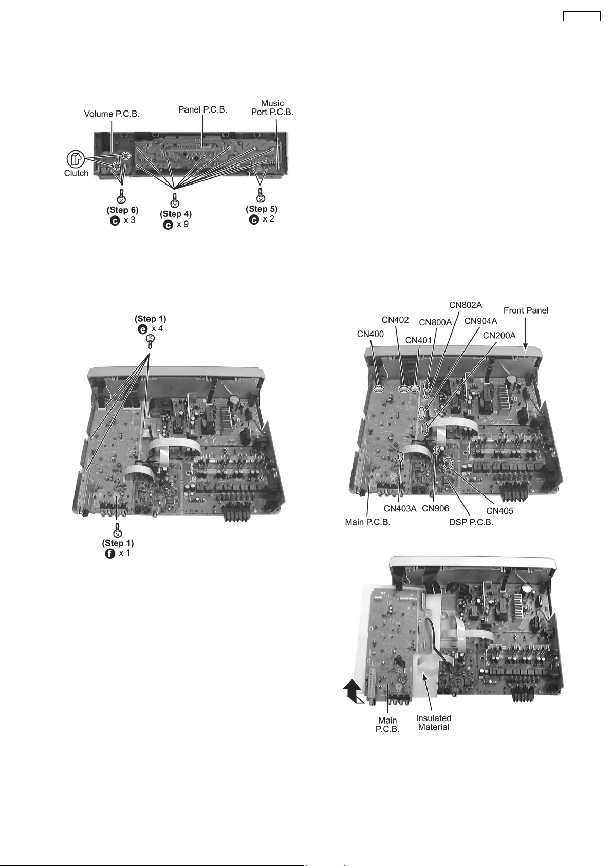
· Disasse mbly of Panel P.C.B. and Music Port P.C.B.
Step 4 : Remove 9 screws at Panel P.C.B..
Step 5 : Remove 2 screws at Music Port P.C.B..
· Disasse mbly of Volume P.C.B.
Step 6 : Remove 3 screws at Volume P.C.B..
Step 7 : Release 2 clutchs.
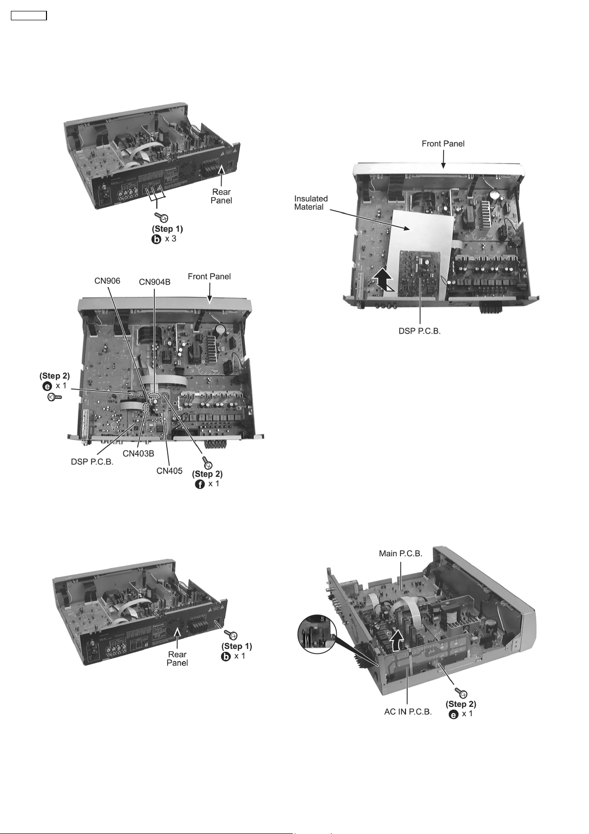
8.8. Disassembly of Main P.C.B.
· Follow the (Step 1) - (Step 3) of item 8.4. - Disassembly of Top Cabinet
· Follow the (Step 1) - (Step 3) of item 8.5. - Disassembly of Rear Panel
Step 1 : Remove 5 screws at Main P.C.B..
Step 2 : Disconnect FFC cables (CN400, CN402, CN401,
CN800A, CN802A, CN904A, CN200A and CN403A) at Main
P.C.B. .
Step 3 : Disconnect 2 connectors (CN906 & CN405) at DSP
P.C.B..
Step 4 : Lift up and remove the Main P.C.B. as picture shown.
17
SA-HT40EE
8.9. Disassembly of DSP P.C.B.
· Follow the (Step 1) - (Step 3) of item 8.4. - Disassembly of Top Cabinet
Step 1 : Remove 3 screws at rear panel.
Step 2 : Remove 2 screws at DSP P.C.B..
Step 3 : Disconnect 4 connectors (CN906, CN904B, CN405
&CN403B) at DSP P.C.B..
Step 4 : Lift up and remove the DSP P.C.B. as the arrow
shown.
8.10. Disassembly of AC In P.C.B.
· Follow the (Step 1) - (Step 3) of item 8.4. - Disassembly of Top Cabinet
Step 1 : Remove 1 screw at rear panel.
Step 2 : Remove 1 screw at AC In P.C.B..
Caution:
Remember to use tie wraps to tie red/ white wires between (AC
In P.C.B. and Power P.C.B.) to the side of AC In P.C.B. after
repair or troubleshooting.
18
SA-HT40EE
Step 3 : Lift up and place AC In P.C.B. as picture shown.
Note:
Caution when lift up the AC In P.C.B..
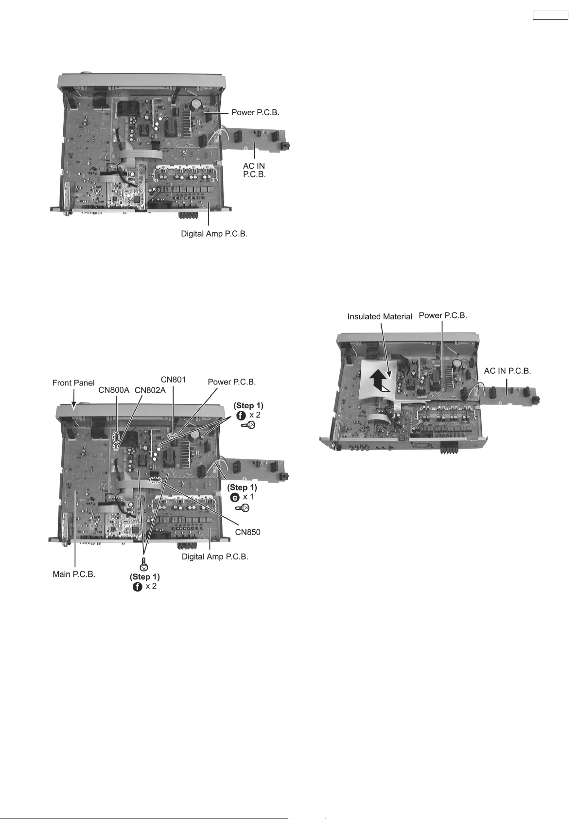
8.11. Disassembly of Power P.C.B.
· Follow the (Step 1) - (Step 3) of item 8.4. - Disassembly of Top Cabinet
· Follow the (Step 1) - (Step 3) of item 8.10. - Disassembly of AC In P.C.B.
Step 1 : Remove 5 screws at Power P.C.B..
Step 2 : Disconnect 2 connectors (CN800A & CN802A) at Main
P.C.B..
Step 3 : Disconnect 1 connector (CN801) at Power P.C.B..
Step 4 : Disconnect 1 connector (CN850) at Digital Amp P.C.B..
Step 5 : Lift up the Power P.C.B. as picture shown.
19
SA-HT40EE
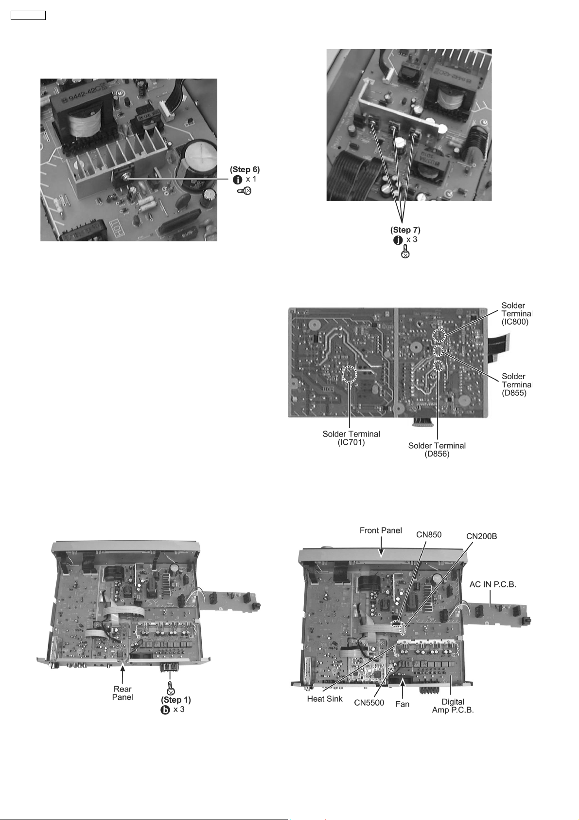
· Replacement of the Power Supply IC and Diode
Step 6 : Remove 1 screw (from IC701).
Step 7 : Remove 3 screws (from IC800, D855 and D856).
Step 8 : Flip over the Power P.C.B..
Step 9 : Desold er the terminal to replace the components.
8.12. Disassembly of Digital Amp P.C.B.
· Follow the (Step 1) - (Step 3) of item 8.4. - Disassembly of Top Cabinet
· Follow the (Step 1) - (Step 3) of item 8.10. - Disassembly of AC In P.C.B.
Step 1 : Remove 3 screws at rear panel.
Step 2 : Detach FFC cables (CN5500, CN200B & CN850) at
Digital Amp P.C.B..
Step 3 : Remove 5 screws at Digital Amp P.C.B..
20
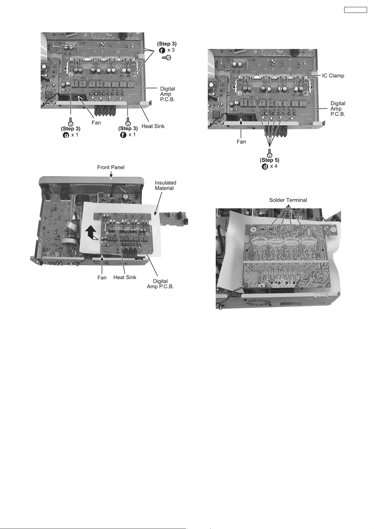
Step 4 : Lift up and remove the Digital Amp P.C.B. as arrow
shown.
SA-HT40EE
· Replacement of the Power Amp IC
Step 5 : Remove 4 screws at the IC Clamp.
Step 6 : Flip over Digital Amp P.C.B..
Step 7 : Desold er the terminal to replace the components.
21
SA-HT40EE
9 Service Position
Note:
Checking of all Major P.C.B. (Main P.C.B., DSP P.C.B., AC In P.C.B., Digital Amp P.C.B., Power P.C.B., Panel P.C.B., Music Port
P.C.B. & Volume P.C.B.) can be carried out using below procedures.
For the disassembling procedure, see Section 8.
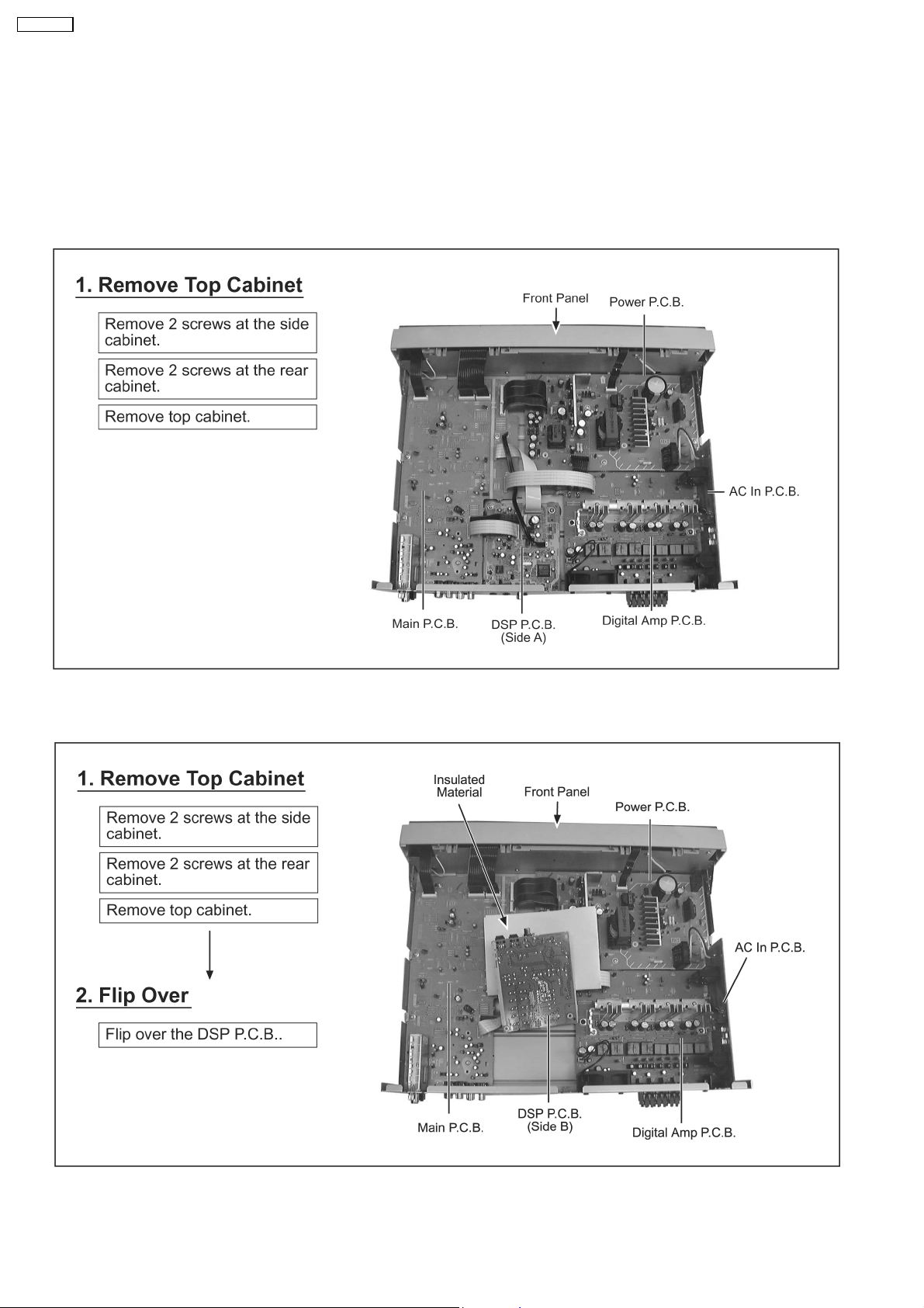
9.1. Checking the DSP P.C.B. (Side A) & AC In P.C.B.
9.2. Checking the DSP P.C.B. (Side B)
22
 Loading...