

Panasonic SAHT-330-EB Service manual
A
A
A
1
1
ORDER NO. MD0506225C2
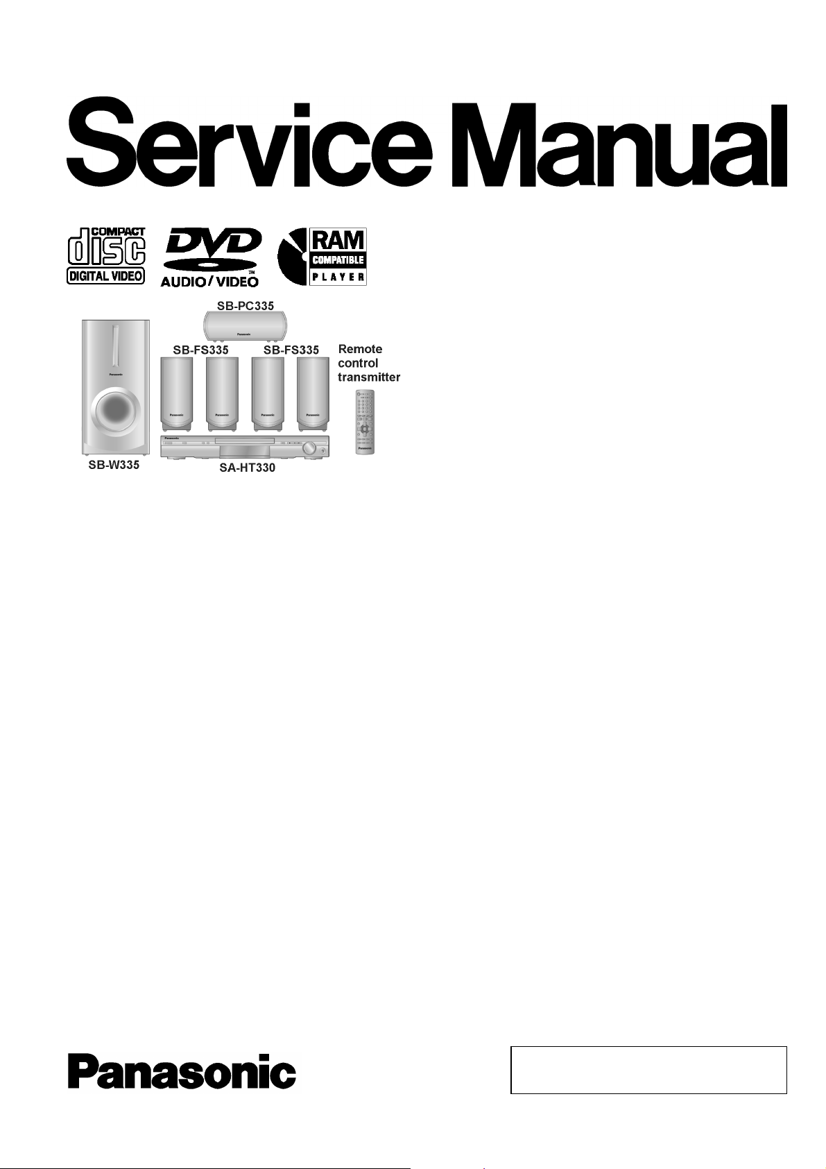
DVD Home Theater Sound System
SA-HT330EB
Colour
(S)... Silver Type
Specification
n Amplifier Section
RMS Output power : Dolby Digital Mode
Front Ch 65 W per channel (6 Ω ), 1 kHz,
10% THD
Surround Ch 65 W per channel (6 Ω ), 1 kHz,
10% THD
Center Ch 65 W per channel (6 Ω ), 1 kHz,
10% THD
Subwoofer Ch 75 W per channel (4 Ω ), 100 kHz,
10% THD
Total RMS Dolby Digital mode
power
DIN Output Power : Dolby Digital Mode
Front Ch 55 W per channel (6 Ω ), 1 kHz,
Surround Ch 55 W per channel (6 Ω ), 1 kHz,
Center Ch 55 W per channel (6 Ω ), 1 kHz,
Subwoofer Ch 65 W per channel (4 Ω ), 100 Hz,
Total DIN Dolby Digital mode
power
n FM/AM Tuner, Terminals Section
Preset station FM 15 stations
AM/MW 15 stations
Frequency Modulation (FM)
Frequency range 87.50 - 108.00 MHz (50-kHz step)
400 W
1% THD
1% THD
1% THD
1% THD
340 W
Sensitivity 1.5 µV
S/N 26 dB 1.2 µV
ntenna terminals 75 Ω (unbalance)
mplitude Modulation (AM/MW)
Frequency range 522 - 1629 kHz (9 - kHz step)
M Sensitivity S/N 20 dB at 999
kHz
Phone jack
Terminal Stereo, 3.5 mm jack
n Disc Section
Discs played ( 8 cm or 12 cm)
(1) DVD-RAM (DVD-VR compatible, JPEG formatted discs)
(2) DVD-Audio
(3) DVD-Video
(4) DVD-R, DVD-RW (DVD-Video compatible)
+R, +RW (video compatible)
(5) CD-Audio (CD-DA)
(6) Video CD
(7) SVCD (Conforming to IEC62107)
(8) CD-R/RW (CD-DA, Video-CD, SVCD, MP3, WMA, JPEG
formatted disc)
(9) MP3/WMA*
l Compatible compression rate:
MP3 : between 32 kbps and 320 kbps
WMA : between 48 kbps and 320 kbps
(10) JPEG*
l Exif Ver 2.1 JPEG Baseline files
560 µV/m
© 2005 Matsushita Electric Industrial Co. Ltd.. All
rights reserved. Unauthorized copying and
distribution is a violation of law.
A
SA-HT330EB
l Picture resolution : between 320 x 240 and 6144 x 4096 pixels (sub
sampling is 4:2:2 or 4:2:0)
(11) HighMAT Level 2 (Audio and Image)
The total combined maximum number of recognizable audio and
picture contents and groups: 4000 audio and picture contents and
400 groups.
Pick up
Wavelength CD 785 nm
DVD 662 nm
Laser power CLASS 2 / CLASS 3A
udio output (Disc)
Number of channels 5.1ch (FL, FR, C, SL, SR, SW)
n Video Section
Video system
Signal system PAL625/50, PAL525/60, NTSC
Composite video output
Output level 1Vp-p(75Ω)
Terminal Pin jack (1 system)
Scart jack (1 system)
S-video output
Y output level 1Vp-p(75Ω)
C output level PAL; 0.3 Vp-p (75 Ω)
NTSC; 0.286 Vp-p (75 Ω )
Terminal S terminal (1 system)
Scart jack (1 system)
Component video output
[NTSC: 525 (480) p/525 (480) i, PAL: 625 (576) p/625 (576) i]
Y output level 1Vp-p(75Ω)
PB output level 0.7 Vp-p (75 Ω)
PR output level 0.7 Vp-p (75 Ω)
Terminal Pin jack (Y: green, PB: blue,
PR: red) (1 system)
RGB video output
R output level 0.7 Vp-p (75 Ω)
G output level 0.7 Vp-p (75 Ω)
B output level 0.7 Vp-p (75 Ω)
Terminal Scart jack (1 system)
n General
Power supply AC 230 - 240 V, 50 Hz
Power consumption Main unit 80 W
Dimensions (W x H x D) 430 mm x 60 mm x 337 mm
Mass Main unit 3.3 kg
Operating temperature range +5 °C to +35 °C
Operating humidity range 5%to90%RH(no
condensation)
Power consumption in standby
mode
Notes :
1. Specifications are subject to change without notices.
Mass and dimensions are approximate.
2. Total harmonic distortion is measured by the digital spectrum
analyzer.
approx 0.5 W
CONTENTS
Page Page
1 Safety Precautions
1.1. GENERAL GUIDELINES
2 Caution for AC Mains Lead
3 Before Repair and Adjustment
4 Protection Circuitry
5 Prevention of Electro Static Discharge (ESD) to
Electrostatically Sensitive (ES) Devices
6 Handling the Lead-free Solder
6.1. About lead free solder (PbF)
7 Precaution of Laser Diode
8 Handling Precautions for Optical Pickup Unit
8.1. Cautions to be taken in handling the Optical Pickup Unit
8.2. Cautions to be taken when replacing the Optical Pickup
Unit
8.3. Grounding for electrostatic breakdown prevention
9 Accessories
10 Operation Procedures
4
4
11 Disc information
12 About HighMAT
5
6
6
7
7
7
8
9
9
9
9
11
12.1. What 痴 HighMAT?
12.2. Why take advantage of HighMAT?
12.3. Benefits of HighMAT?
13 Assembling and Disassembling
13.1. Disassembly flow chart
13.2. P.C.B. Locations
13.3. Disassembly of Top Cabinet
13.4. Disassembly of SMPS Module P.C.B.
13.5. Disassembly of Rear Panel
13.6. Disassembly of AC Inlet P.C.B.
13.7. Disassembly of Digital Amplifier (side A & side B) P.C.B.
2
12
13
15
15
15
16
19
19
20
21
21
21
22
22

SA-HT330EB
13.8. Disassembly of DVD Lid (when taking out disc manually)
13.9. Disassembly of Front Panel
13.10. Disassembly of Headphone, Panel and Tact Switch P.C.B.
13.11. Disassembly of DVD Mechanism unit
13.12. Disassembly of Main P.C.B.
13.13. Disassembly and Assembly Mechanism Unit
14 Service Positions
14.1. Checking procedure
15 Optical Pick-up Self-Diagnosis and Replacement Procedure
15.1. Optical Pickup Breakdown Diagnosis
15.2. Service Mode Table 1
15.3. DVD Self Diagnostic Function-Error Code
15.4. Service mode table 2
15.5. Sales demonstration lock function
15.6. Handling After Completing Repairs
16 Self-Diagnosis Function
16.1. Automatic Displayed Error Codes
16.2. Memorized Error Codes
17 Service Precautions
17.1. Recovery after the DVD player is repaired
17.2. Firmware version-up of the DVD player
18 Adjustment Procedure
18.1. Service Tools and Equipment
18.2. Important points in adjustment
18.3. Storing and Handling Test Discs
18.4. Optical adjustment
19 Abbreviati ons
20 Voltage Measurement and Waveform Chart
20.1. Voltage Measurement
20.2. Waveform Chart
21 Block Diagram
23
23
21.1. DVD MODULE BLOCK
21.2. MAIN BLOCK
22 Notes of Schematic Diagram
24
25
23 Schematic Diagram
25
26
34
34
23.1. OPTICAL PICKUP UNIT CIRCUIT
23.2. DVD MODULE CIRCUIT
23.3. MAIN CIRCUIT
23.4. PANEL CIRCUIT
23.5. SMPS MODULE CIRCUIT and AC INLET CIRCUIT
36
36
37
37
39
41
41
42
42
42
43
43
43
44
44
44
44
45
47
49
23.6. DIGITAL AMPLIFIER CIRCUIT
23.7. HEADPHONE CIRCUIT, TACT SWITCH CIRCUIT and CD
TRAY LOADING CIRCUIT
24 Printed Circuit Board
24.1. DVD MODULE P.C.B
24.2. MAIN P.C.B.
24.3. PANEL P.C.B, HEADPHONE P.C.B and TACT SWITCH
P.C.B
24.4. DIGITAL AMPLIFIER P.C.B
24.5. CD TRAY LOADING P.C.B and AC INLET P.C.B
25 Wiring Connection Diagram
26 Illustration of IC 痴, Transistors and Diodes
27 Terminal Function of ICエs
27.1. IC2018 (C2CBHG000197): MICROPROCESSOR IC
28 Parts Location and Replacement Parts List
28.1. DVD Loading Mechanisms
28.2. Cabinet Part List
28.3. Electrical Part List
28.4. Packaging Materials & Accessories Parts List
28.5. Packaging
49
54
55
55
58
64
65
65
66
73
82
83
85
88
89
89
91
93
94
95
96
98
99
99
100
101
103
106
116
116
3
SA-HT330EB
1 Safety Precautions
1.1. GENERAL GUIDELINES
1. When servicing, observe the original lead dress. If a short circuit is found, replace all parts which have been overheated or
damaged by the short circuit.
2. After servicing, ensure that all the protective devices such as insulation barriers, insulation papers shields are properly installed.
3. After servicing, check for leakage current checks to prevent from being exposed to shock hazards.
1.1.1. LEAKAGE CURRENT COLD CHECK
1. Unplug the AC cord and connect a jumper between the two prongs on the plug.
2. Using an ohmmeter measure the resistance value, between the jumpered AC plug and each exposed metallic cabinet part on
the equipment such as screwheads, connectors, control shafts, etc. When the exposed metallic part has a return path to the
chassis, the reading should be between 1MΩand 5.2Ω.
When the exposed metal does not have a return path to the chassis, the reading must be
.
Fig. 1
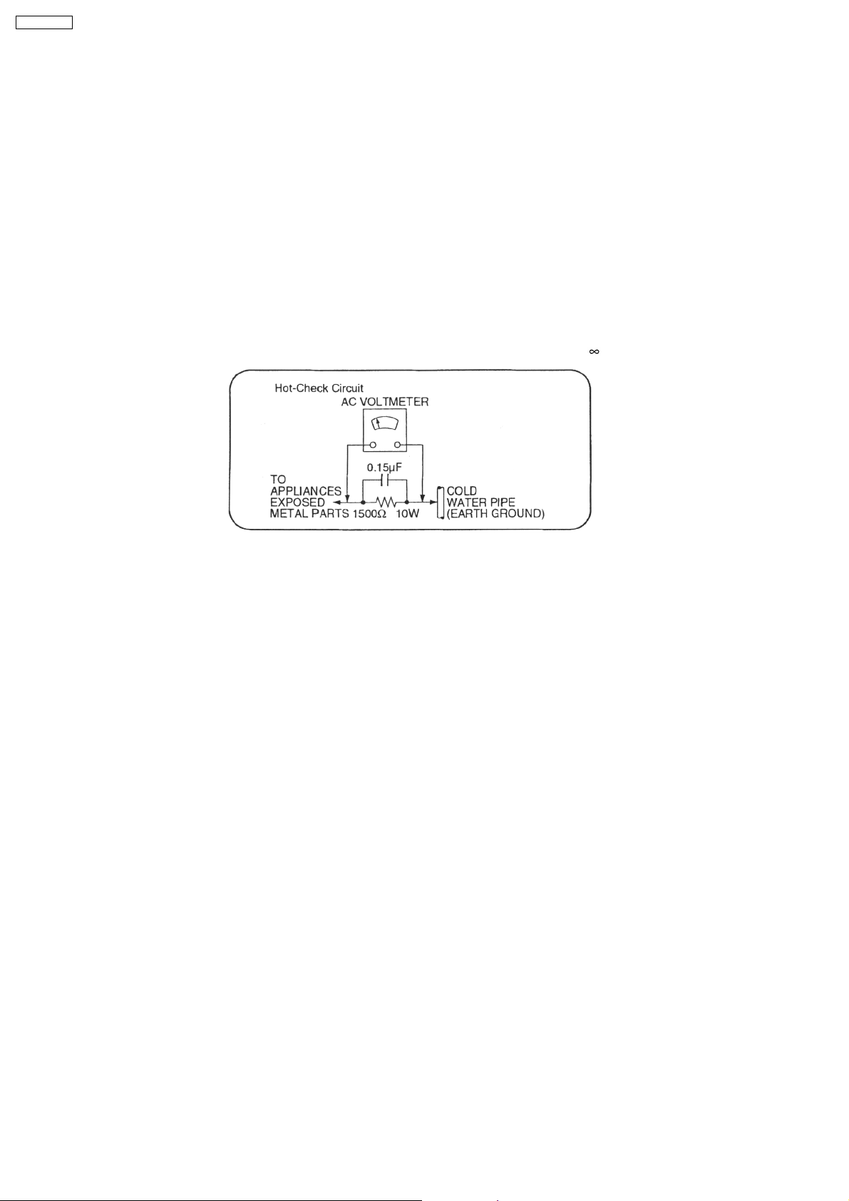
1.1.2. LEAKAGE CURRENT HOT CHECK (See Figure 1.)
1. Plug the AC cord directly into the AC outlet. Do not use an isolation transformer for this check.
2. Connect a 1.5kΩ, 10 watts resistor, in parallel with a 0.15µF capacitors, between each exposed metallic part on the set and a
good earth ground such as a water pipe, as shown in Figure 1.
3. Use an AC voltmeter, with 1000 ohms/volt or more sensitivity, to measure the potential across the resistor.
4. Check each exposed metallic part, and measure the voltage at each point.
5. Reverse the AC plug in the AC outlet and repeat each of the above measurements.
6. The potential at any point should not exceed 0.75 volts RMS. A leakage current tester (Simpson Model 229 or equivalent) may
be used to make the hot checks, leakage current must not exceed 1/2 milliamp. should the measurement is outside of the limits
specified, there is a possibility of a shock hazard, and the equipment should be repaired and re-checked before it is returned
to the customer.
4
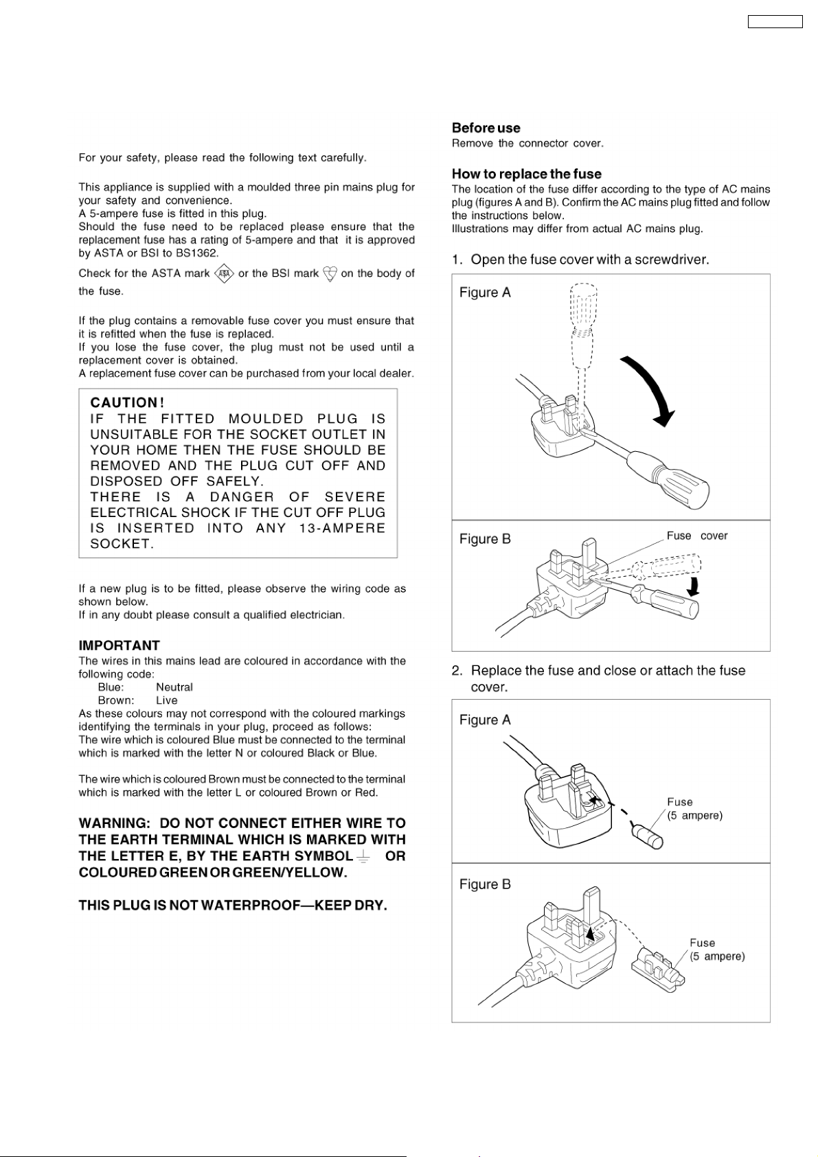
2 Caution for AC Mains Lead
SA-HT330EB
5

SA-HT330EB
3 Before Repair and Adjustment
Disconnect AC power, discharge Power Supply Capacitors C506, C507 & C508 through a 10Ω, 1W resistor to ground.
DO NOT SHORT-CIRCUIT DIRECTLY (with a screwdriver blade, for instance), as this may destroy solid state devices.
After repairs are completed, restore power gradually using a variac, to avoid overcurrent.
· Current consumption at AC 230-240 V, 50 Hz in NO SIGNAL mode should be ~650 mA.
4 Protection Circuitry
The protection circuitry may have operated if either of the following conditions are noticed:
· No sound is heard when the power is turned on.
· Sound stops during a performance.
The function of this circuitry is to prevent circuitry damage if, for example, the positive and negative speake r connection wires are
"shorted", or if speaker systems with an impedance less than the indicated rated impedance of the amplifier are used.
If this occurs, follow the procedure outlines below:
1. Turn off the power.
2. Determine the cause of the problem and correct it.
3. Turn on the power once again after one minute.
Note:
When the protection circuitry functions, the unit will not operate unless the power is first turned off and then on again.
6
SA-HT330EB
5 Prevention of Electro Static Discharge (ESD) to
Electrostatically Sensitive (ES) Devices
Some semiconductor (solid state) devices can be damaged easily by electricity. Such components commonly are called
Electrostatically Sensitive (ES) Devices. Examples of typical ES devices are integrated circuits and some field-effect transistors and
semiconductor “chip” components. The following techniques should be used to help reduce the incidence of component damage
caused by electro static discharge (ESD).
1. Immediately before handling any semiconductor component or semiconductor-equiped assembly, drain off any ESD on your
body by touchin g a known earth ground. Alternatively, obtain and wear a commercially available discharging ESD wrist strap,
which should be removed for potential shock reasons prior to applying power to the unit under test.
2. After removing an electrical assembly equiped with ES devices, place the assembly on a conductive surface such as aluminium
foil, to prevent electrostatic charge build up or exposure of the assembly.
3. Use only a grounded-tip soldering iron to solder or unsolder ES devices.
4. Use only an anti-static solder remover device. Some solder removal devices not classified as “anti-static (ESD protected)” can
generate electrical charge to damage ES devices.
5. Do not use freon-propelled chemicals. These can generate electrical charges sufficient to damage ES devices.
6. Do not remove a replacement ES device from its protective package until immediately before you are ready to install it. (Most
replacement ES devices are packaged with leads electrically shorted together by conductive foam, aluminium foil or
comparable conductive material).
7. Immediately before removing the protective material from the leads of a replacement ES device, touch the protective material
to the chassis or circuit assembly into which the device will be installed.
Caution
Be sure no power is applied to the chassis or circuit, and observe all other safety precautions.
8. Minimize bodily motions when handling unpackaged replacement ES devices. (Otherwise harmless motion such as the
brushing together of your clothes fabric or the lifting of your foot from a carpeted floor can generate static electricity (ESD)
sufficient to damage an ES device).
6 Handling the Lead-free Solder
6.1. About lead free solder (PbF)
Distinction of PbF P.C.B.:
P.C.B.s (manufactured) using lead free solder will have a PbF stamp on the P.C.B.
Caution:
· Pb free solder has a higher melting point than standard solder; Typically the melting point is 50 - 70°F (30 - 40°C) higher. Please
use a high temperature soldering iron. In case of soldering iron with temperature control, please set it to 700 ± 20°F (370 ±
10°C).
· Pb free solder will tend to splash when heated too high (about 1100°F/600°C).
· W hen soldering or unsoldering, please completely remove all of the solder on the pins or solder area, and be sure to heat the
soldering points with the Pb free solder until it melts enough.
7
SA-HT330EB
7 Precaution of Laser Diode
Caution :
This product utilizes a laser diode with the unit turned "ON", invisible laser radiation is emitted from the pick up lens.
Wavelength : 780 nm
Maximum output radiation power from pick up : 100 µW/VDE
Laser radiation from pick up unit is safety level, but be sure the followings:
1. Do not disassemble the optical pick up unit, since radiation from exposed laser diode is dangerous.
2. Do not adjust the variable resistor on the pick up unit. It was already adjusted.
3. Do not look at the focus lens using optical instruments.
4. Recommend not to look at pick up lens for a long time.
ACHTUNG :
Dieses Produkt enthält eine Laserdiode. Im eingeschalteten Zustand wird unsichtbare Laserstrahlung von der Lasereinheit
abgestrahlt.
Wellenlänge : 780nm
Maximale Strahlungsleistung der Lasereinheit :100µW/VDE
Die Strahlung an der Lasereinheit ist ungefährlich, wenn folgende Punkte beachtet werden:
1. Die Lasereinheit nicht zerlegen, da die Strahlung an der freigelegten Laserdiode gefährlich ist.
2. Den werkseitig justierten Einstellregler der Lasereinhit nicht verstellen.
3. Nicht mit optischen Instrumenten in die Fokussierlinse blicken.
4. Nicht über längere Zeit in die Fokussierlinse blicken.
ADVARSEL :
I dette a apparat anvendes laser.
CAUTION!
THIS PRODUCT UTILIZES A LASER.
USE OF CONTROLS OR ADJUSTMENTS OR PERFORMANCE OF PROCEDURES OTHER THAN THOSE SPECIFIED HEREIN MAY RESULT
IN HAZARDOUS RADIATION EXPOSURE.
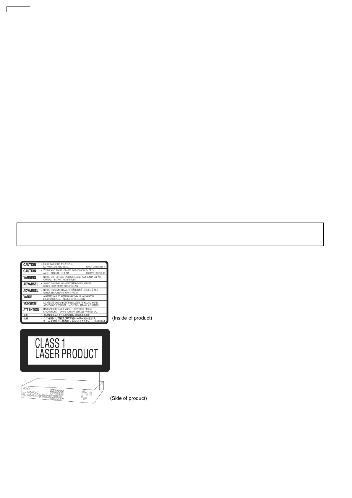
n Use of Caution Labels
8
SA-HT330EB
8 Handling Precautions for Optical Pickup Unit
The laser diode in the optical pickup unit may break down due to static electricity of clothes or human body. Special care must be
taken avoid to electrostatic breakdown when servicing and handlin g the laser diode.
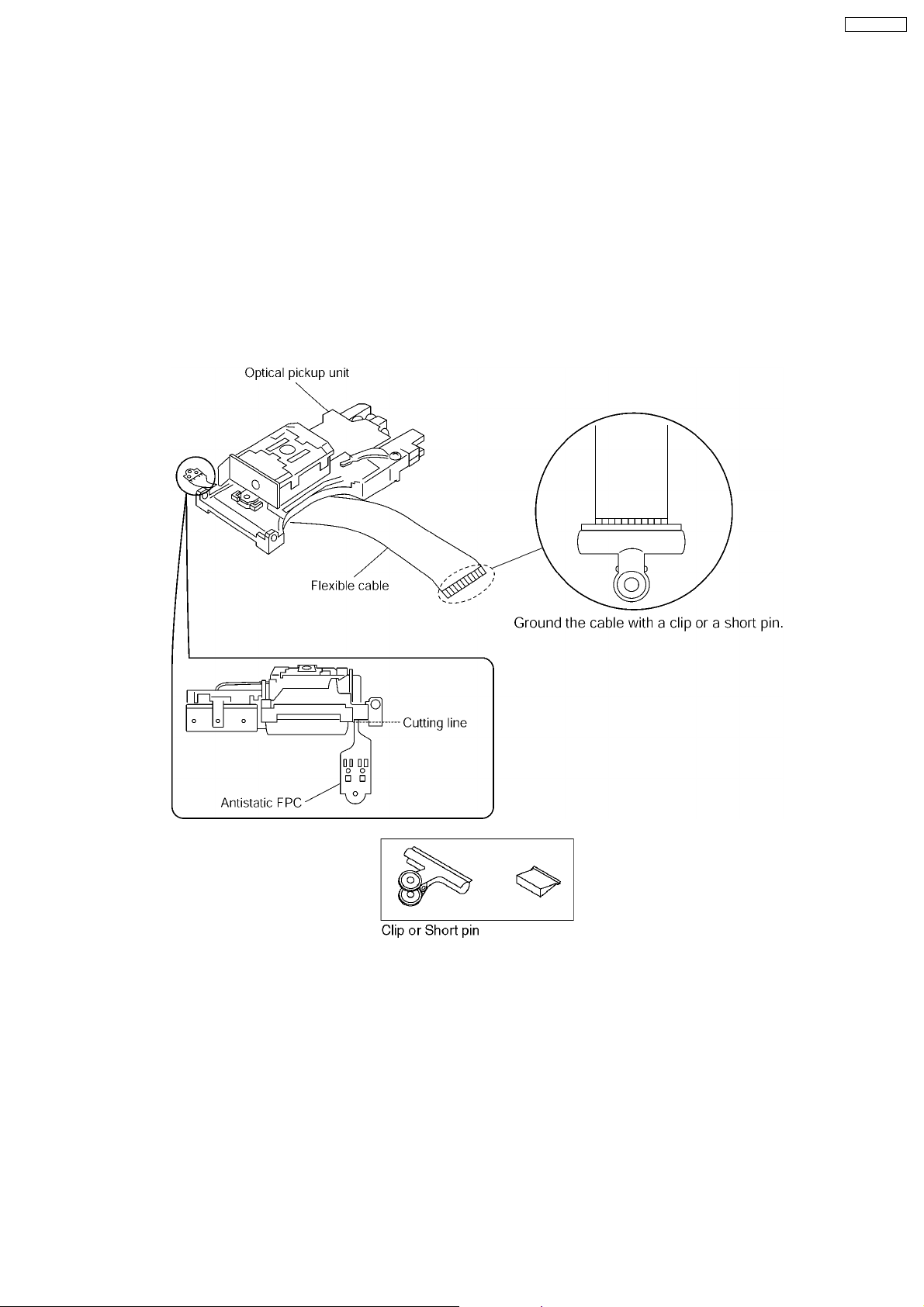
8.1. Cautions to be taken in handling the Optical Pickup Unit
The laser diode in the optical pickup unit may be damaged due to electrostatic discharge generating from clothes or human body.
Special care must be taken avoid to electrostatic discharge damage when servicing the laser diode.
1. Do not give a considerable shock to the optical pickup unit as it has an extremely high-precise structure.
2. To prevent the laser diode from the electrostatic discharge damage, the flexible cable of the optical pickup unit removed should
be short-circuited with a short pin or a clip.
3. The flexible cable may be cut off if an excessive force is applied to it. Use with caution when handling the flexible cable.
4. The antistatic FPC is connected to the new optical pickup unit. After replacing the optical pickup unit and connecting the flexible
cable, cut off the antistatic FPC.
8.2. Cautions to be taken when replacing the Optical Pickup Unit
The flexible cable of the optical pickup unit which was supplie d as a component is equipped with a short clip to prevent the laser
diode from being damaged due to electrostatic discharge. Remove the short clip before connecting the flexible cable and make
sure that the short land is open. (If the flexible cable is short-circuited, remove the solder.)
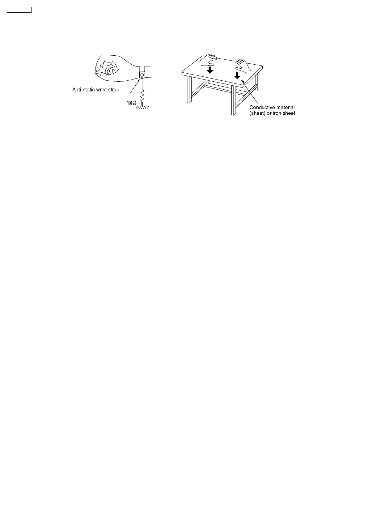
8.3. Grounding for electrostatic breakdown prevention
Some devices such as the DVD player use the optical pickup (laser diode) and the optical pickup will be damaged by static
electricity in the working environment. Proceed servicing works under the working environment where grounding works is
completed.
8.3.1. Worktable grounding
1. Put a conductive material (sheet) or iron sheet on the area where the optical pickup is placed, and ground the sheet.
9
SA-HT330EB
8.3.2. Human body grounding
1. Use the anti-static wrist strap to discharge the static electricity form your body.
10
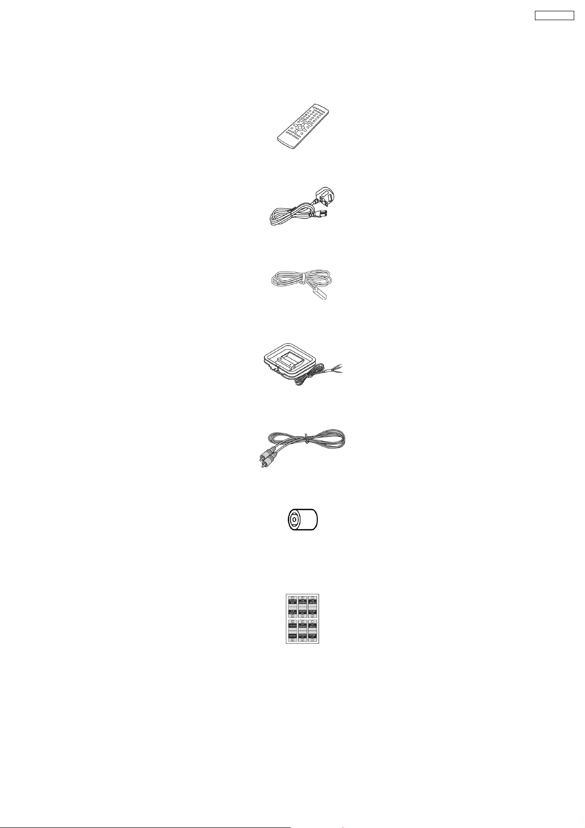
9 Accessories
Note : Refer to Packing Materials & Accessories Parts List (Section 28.4) for the part number.
Remote Control
AC cord
SA-HT330EB
FM indoor antenna
AM loop antenna
Video cable
Antenna
plug
adaptor
Sheet of
Speaker
Cable
Stickers
11
SA-HT330EB
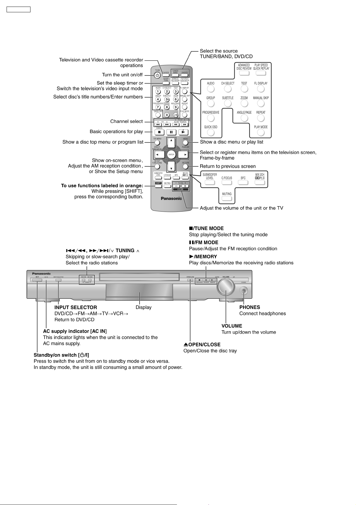
10 Operation Procedures
12
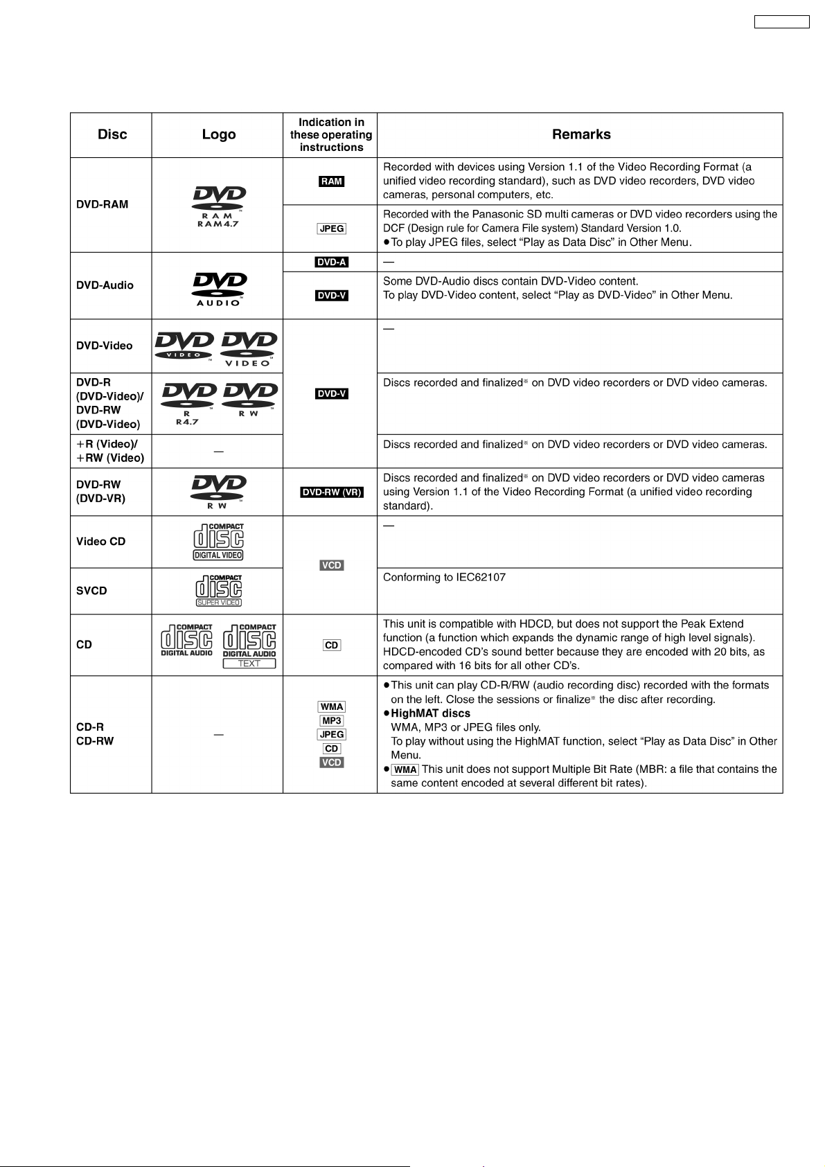
11 Disc information
SA-HT330EB
13
SA-HT330EB
14
SA-HT330EB
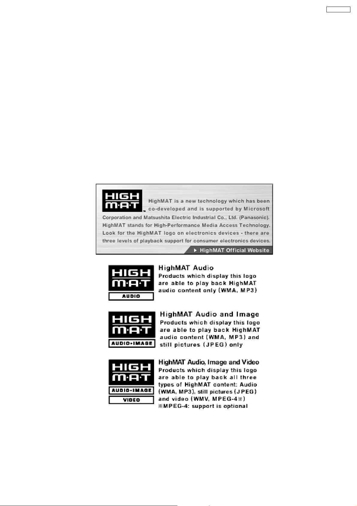
12 About HighMAT
12.1. What’s HighMAT?
Consumers worldwide are using PCs to create their own collections of music, photos and even video by burning them onto CDs.
But how these collections can be experienced across different devices can be confusing to navigate, time consuming to access for
a DVD player, and be incomplete in terms of music information available to the customer.
HighMAT offers a solution to this growing consumer problem. HighMAT dramatically improves the digital media experience on
consumer electronic devices by delivering a simple, standardized approach that allows consumers who have created personal
collections of digital music, photography and video on their PC to:
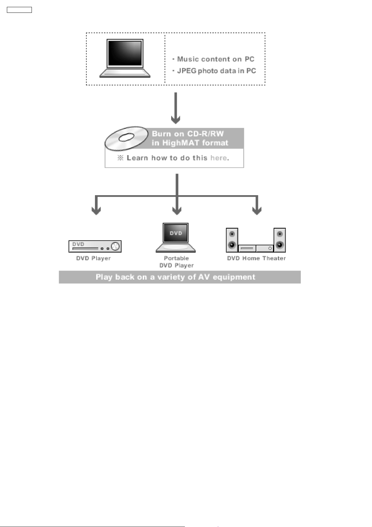
· Create a HighMAT CD or DVD which can be easily played back on consum er electronics devices such as CD and DVD players,
and car stereos.
· Move digital media files (using recordable media such as CD-R and CD-RW) between the PC and various playback devices
such as CD and DVD players.
A new standard for creating personal media on consum er electronic devices, HighMAT enable easier and more seamless
interoperability between Windows PCs and devices designed for your living room, or the car.
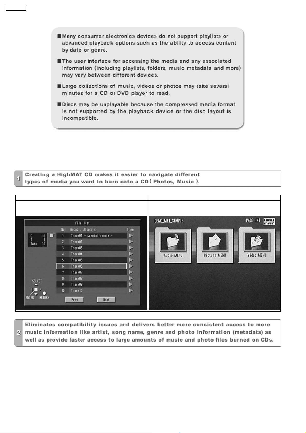
12.2. Why take advantage of HighMAT?
A Problem Defined:Toda y, when consumers create their own digital audio, video or photo collections on CD-R or other physical
formats, there are numerous, inconsistent ways that devices read the data. For the consumer, the playba ck experie nce can be
confusing:
15
SA-HT330EB
A Solution Created: HighMAT delivers a better digital media access experience by creating a standard approach for PCs to
structure digital media on various physical formats and for playback devices to read the data.
12.3. Benefits of HighMAT?
Conventional HighMAT
Even though DVD player is CD-R/RW compatible, the inconsistent ways
that various DVD players can read the music or photos files often leads
to a confusing and inconsistant playback experince.
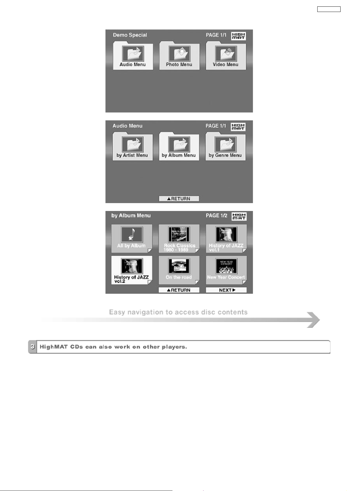
HighMAT compatible products play content back with consistent
interface. This includes products which are JPEG compatible products
without HighMAT support.
16
SA-HT330EB
17
SA-HT330EB
HighMAT is now available for CD Burning and in Leading DVD PlayersHighMAT is a new technology that is now available in leading
software and consumer electronic devices to dramatically improve the digital media experience when you create homemade
CDsHighMAT delivers a simple, standardized way for PC software and consumer electronics devices to talk to each other and work
better together.
When you create your homemade CDs with software that supports HighMAT CD burning, and then play them back on a DVD
player that supports HighMAT, you get better, easier navigation. You get folders you can access with a single click of your DVD
player´s remote control. You can view important information about your music like full song names, artist titles, album names and
genre. And you can get faster startup on your home entertainment device.
To enjoy the benefits of HighMAT, all you need is software that supports HighMAT for CD burning of music or photos, as well as
a home entertainment device like a DVD player that supports HighMAT for playback. Always look for the HighMAT logo on your
software or home entertainment device to ensure it supports the HighMAT experience.
18
SA-HT330EB
13 Assembling and Disassembling
“ATTENTION SERVICER”
Some chassis components may be have sharp edges. Be careful when disassembling and servicing.
1. This section describes procedures for checking the operation of the major printed circuit boards and replacing the main
components.
2. For reassembly after operation checks or replacement, reverse the respective procedures.
Special reassembly procedures are described only when required.
3. Select items from the following index when checks or replacement are required.
· Disassembly of Top Cabinet
· Disassembly of SMPS Module P.C.B.
· Disassembly of Rear Panel
· Disassembly of AC Inlet P.C.B.
· Disassembly of Digital Amplifier (side A & side B) P.C.B.
· Disassembly of DVD Lid (when taking out disc manually)
· Disassembly of Front Panel
· Disassembly of Headphone, Panel and Tact Switch P.C.B.
· Disassembly of DVD Mechanism unit
· Disassembly of Main P.C.B.
Warning:
This product uses a laser diode. Refer to “Precaution of Laser Diode”.
ACHTUNG:
Die Lasereinheit nicht zerlegen.
Die Lasereinheit darf nur gegen eine vom Hertsteller spezifizierte Einheit ausgetauscht werden.
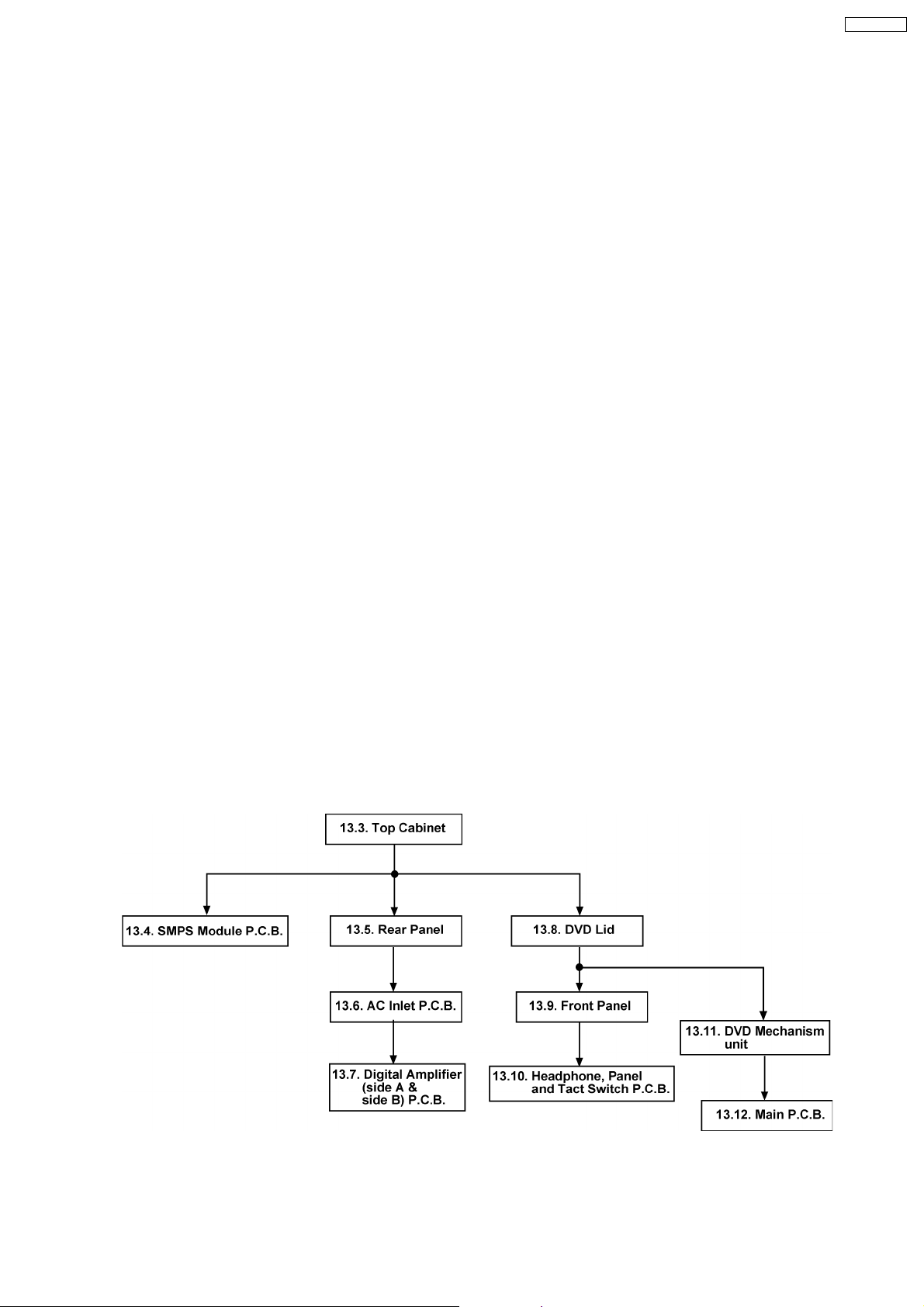
13.1. Disassembly flow chart
The following chart is the procedure for disassembling the casing and inside parts for internal inspection when carrying out the
servicing.
To assemble the unit, reverse the steps shown in the chart below.
19
SA-HT330EB
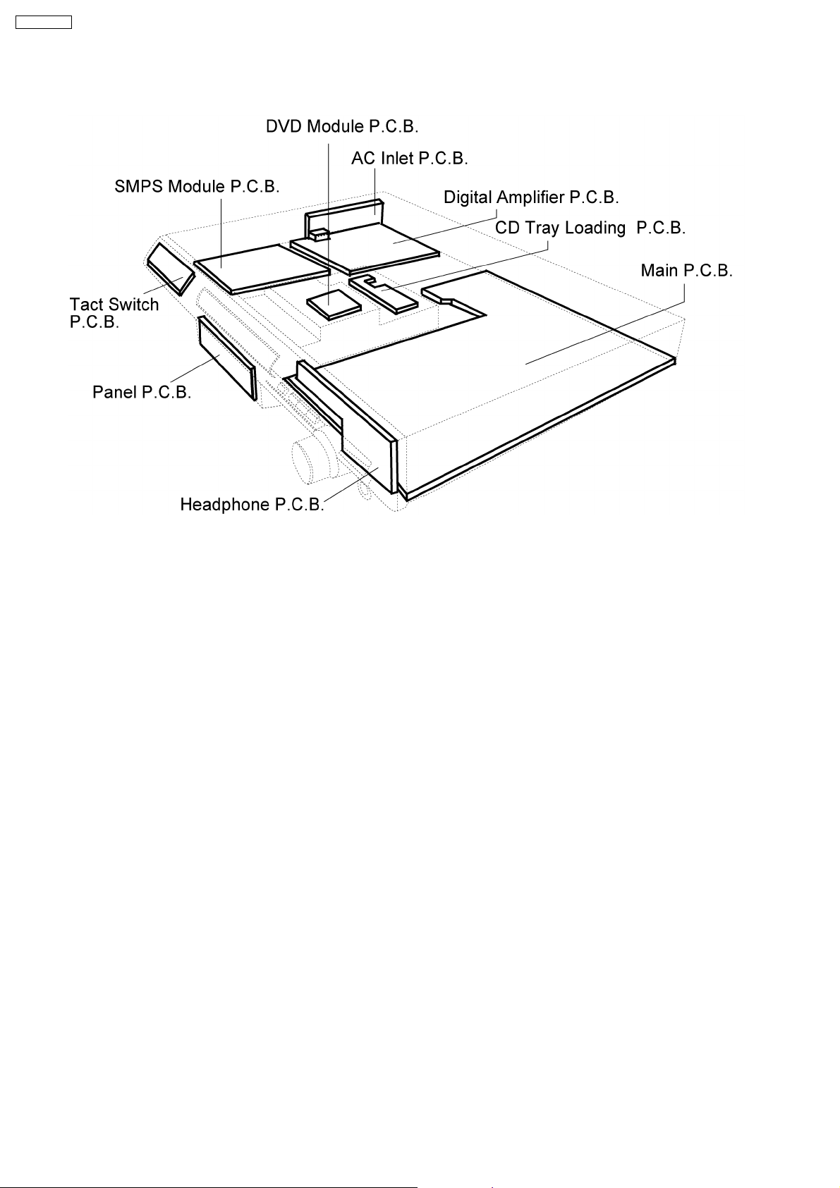
13.2. P.C.B. Locations
20
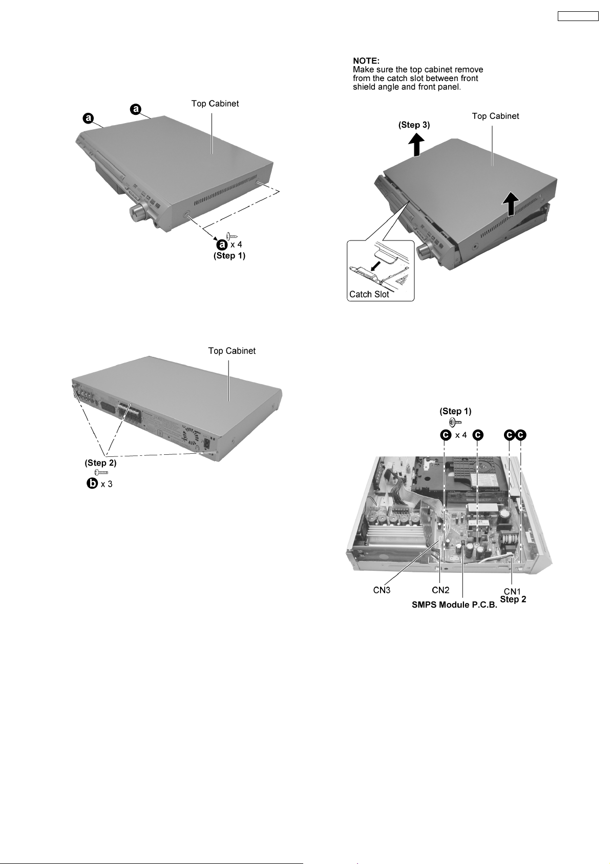
13.3. Disassembly of Top Cabinet
Step 1 : Remove 4 screws.
SA-HT330EB
Step 2 : Remove 3 screws.
Step 3 : Remove Top Cabinet as arrow shown.
13.4. Disassembly of SMPS Module
P.C.B.
· Follow the (Step 1) - (Step 3) of item 13.3.
Step 1 : Remove 4 screws.
Step 2 : Detach connec tor (CN1, CN2, CN3), and remove
SMPS Module P.C.B.
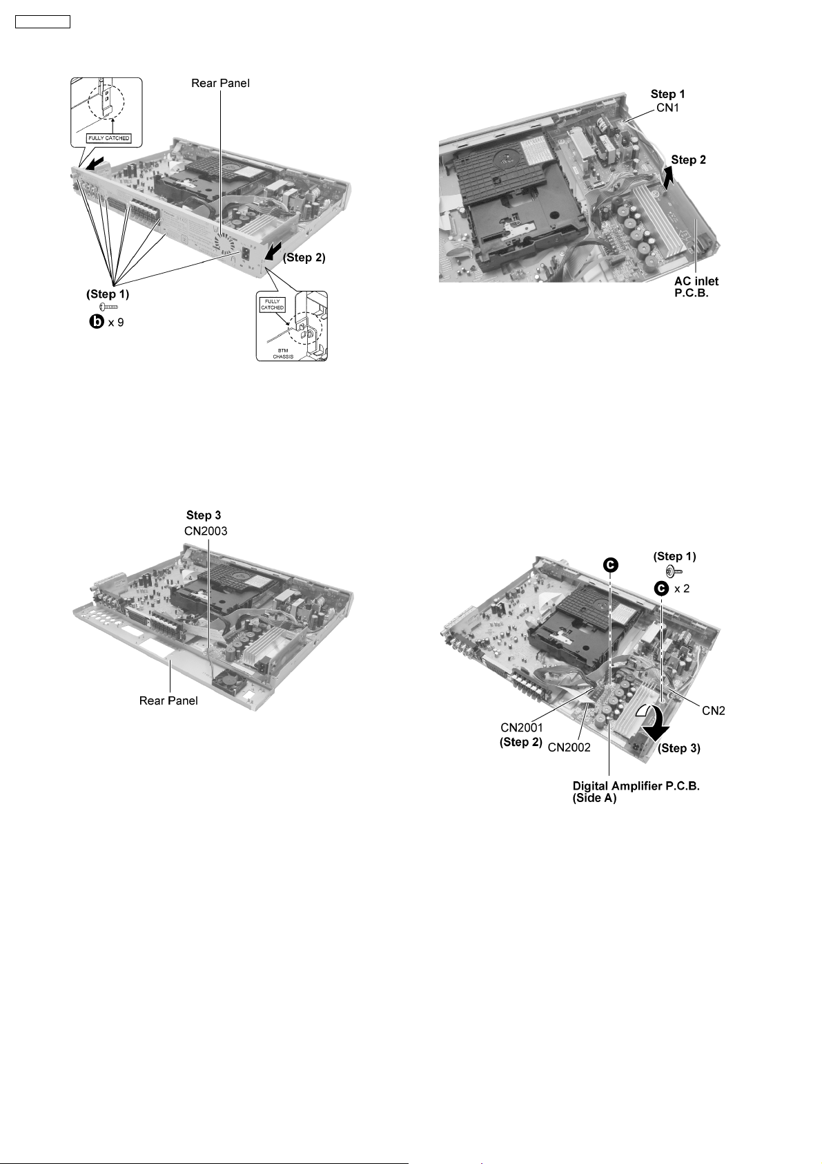
13.5. Disassembly of Rear Panel
· Follow the (Step 1) - (Step 3) of item 13.3.
21
SA-HT330EB
Step 1 : Remove 9 screws.
Step 2 : Remove the rear panel as arrows shown.
Note : Be careful of the both side catches when remove the
rear panel.
Step 1 : Detach connector CN1.
Step 2 : Remove AC inlet P.C.B. as arrow shown.
13.7. Disassembly of Digital
Amplifier (side A & side B)
P.C.B.
Step 3 : Detach Fan connector CN2003 to remove rear panel.
13.6. Disassembly of AC Inlet P.C.B.
· Follow the (Step 1) - (Step 3) of item 13.3.
· Follow the (Step 1) - (Step 3) of item 13.5.
· Follow the (Step 1) - (Step 3) of item 13.3.
· Follow the (Step 1) - (Step 3) of item 13.5.
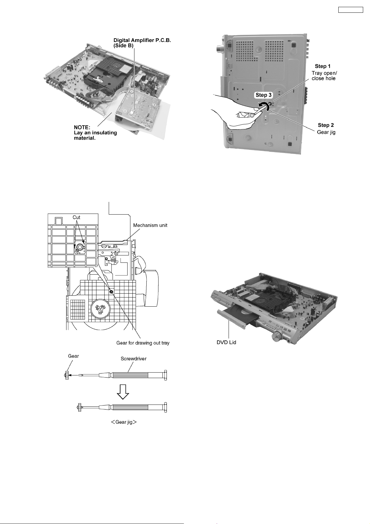
Step 1 : Remove 2 screws.
Step 2: Detach connector (CN2, CN2001) and FFC (CN2002).
Step 3: Flip over the Digital Amplifier P.C.B. (Side A).
22
SA-HT330EB
13.8. Disassembly of DVD Lid (when
taking out disc manually)
· Follow the (Step 1) - (Step 3) of item 13.3.
Step 1 : Separates the gear for drawing out tray from the
mechanism unit. It inserts a screw driver in the gear. (The gear
jig)
Step 2 : Insert the gear jig into the tray open/ close hole.
Step 3 : Turn the gear jig counterclockwise to open the tray.
Note : Do not use force to push the tray backwards as it can
damage the mechanism unit.
Turn the gear jig clockwise to return tray.
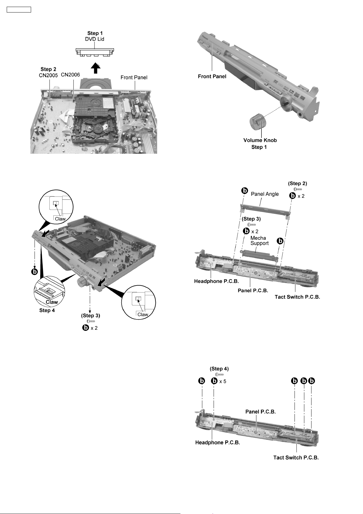
13.9. Disassembly of Front Panel
· Follow the (Step 1) - (Step 3) of item 13.3.
· Follow the (Step 1) - (Step 3) of item 13.8.
23
SA-HT330EB
Step 1 : Remove the DVD Lid from the tray section.
Step 2 : Detach connector (CN2005) and FFC (CN2006).
Step 1 : Remove Volume Knob.
Step 2 : Remove 2 screws and panel angle.
Step 3 : Remove 2 screws and Mecha Support.
Step 3 : Remove 2 screws.
Step 4: Release all the claws and remove the front panel as
arrow shown.
13.10. Disassembly of Headphone,
Panel and Tact Switch P.C.B.
· Follow the (Step 1) - (Step 3) of item 13.3.
· Follow the (Step 1) - (Step 3) of item 13.8.
· Follow the (Step 1) - (Step 4) of item 13.9.
Step 4 : Remove 5 screws and Remove Headphone, Panel and
24
Tact Switch P.C.B.
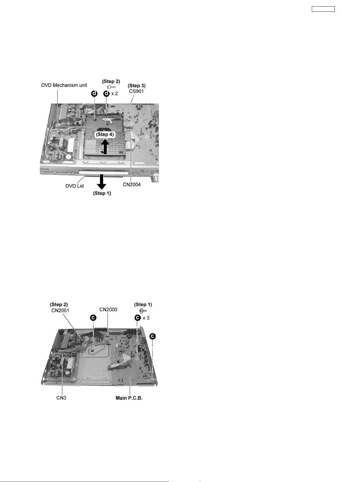
13.11. Disassembly of DVD
Mechanism unit
· Follow the (Step 1) - (Step 3) of item 13.3.
· Follow the (Step 1) - (Step 3) of item 13.8.
SA-HT330EB
Step 1 : Remove DVD Lid as arrow shown.
Step 2 : Remove 2 screws.
Step 3 : Detach FFC (CN2004) and connector (CS901).
Step 4 : Remove DVD mechanism unit as arrow shown.
13.12. Disassembly of Main P.C.B.
· Follow the (Step 1) - (Step 3) of item 13.3.
· Follow the (Step 1) - (Step 3) of item 13.5.
· Follow the (Step 1) - (Step 3) of item 13.8.
· Follow the (Step 1) - (Step 4) of item 13.9.
· Follow the (Step 1) - (Step 4) of item 13.11.
Step 1 : Remove 3 screws.
Step 2 : Detach FFC (CN2000), connector (CN2001, CN3) and
remove main P.C.B.
25
SA-HT330EB
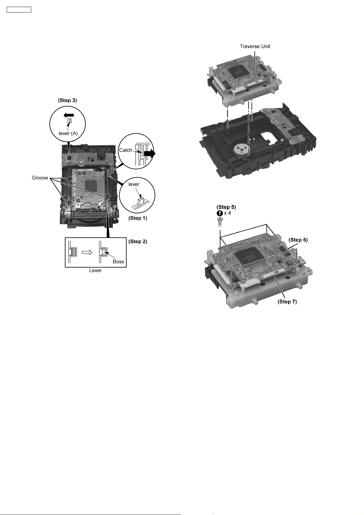
13.13. Disassembly and Assembly Mechanism Unit
13.13.1. Replacement of Traverse Unit.
Step 1: Slide the lever backward to the furthest.
Step 2: While bending the catch at right to the lever to the right
direction, slide the lever further until it stops. (The groove at
right opens, the boss can be seen.)
Step 3: Press lever (A) to the left. (Two grooves at left open.)
· Disassembly of DVD Module P.C.B.
Step 5: Remove 4 screws.
Step 4: Take out the traverse Unit.
Step 6: Detach 15 P FFC Board (FP8271).
Step 7: Detach 20P FFC Board (FP8501).
13.13.2. Replacement of Tray.
· Follow the (Step 1) - (Step 7) of item 13.13.1 - Replacement of Traverse Unit
Step 1: While pressing the stopper to the arrow direction, slide
the guide tray unit to remove.
26
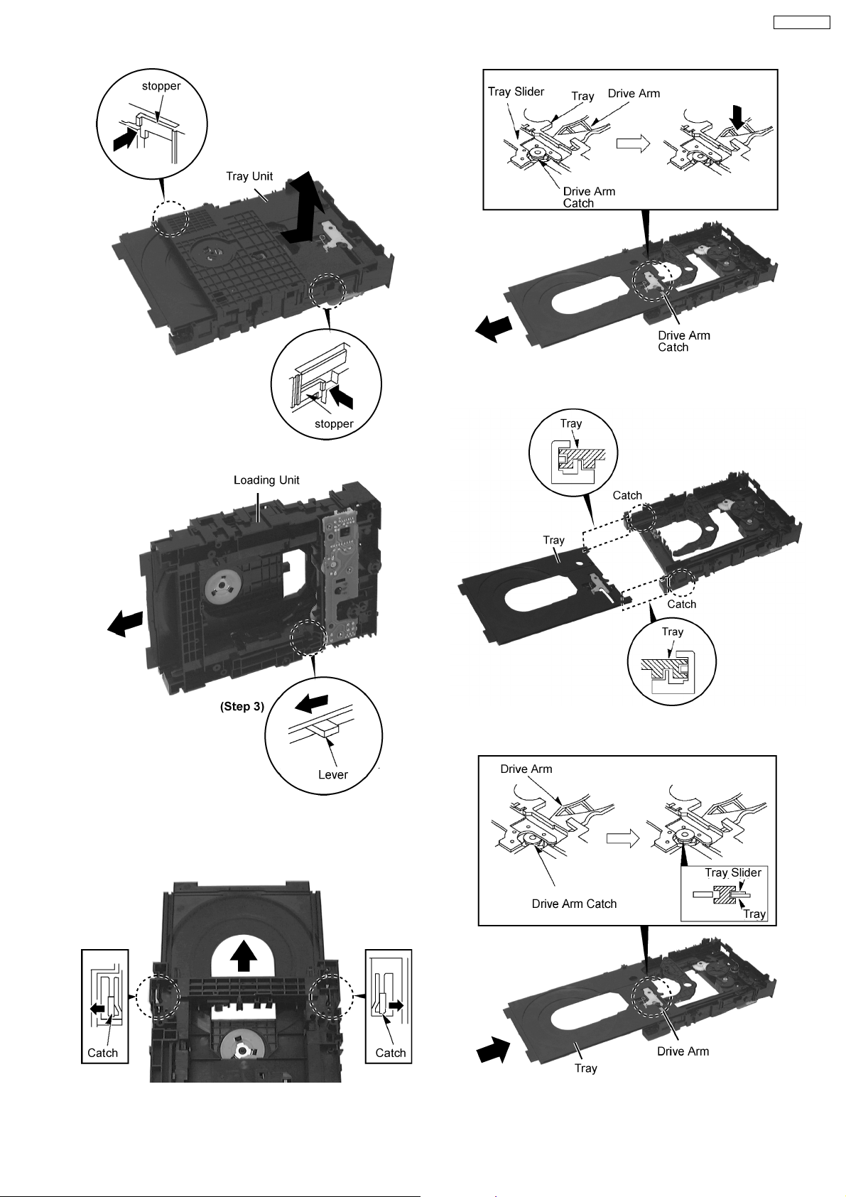
· Fixing the Tray
Step 1: Insert Tray slightly into groove of chassis.
SA-HT330EB
Step 2: Stand the Loading Unit.
Step 3: Push the lever forward (the tray will move).
Step 4: Widen the catches at both sides and pull out the tray.
(The tray will stop after a few slides)
Step 2: Insert Tray into the area to avoid catching the
mechanism chassis claw.
Step 5: Remove Drive Arm Catch from Tray Slider and Tray.
Step 3: Latch Drive Arm Catch onto Tray and Tray Slider.
27
SA-HT330EB
Step 4: Push Tray. Step 5: Check Tray and Drive Arm move smoothly.
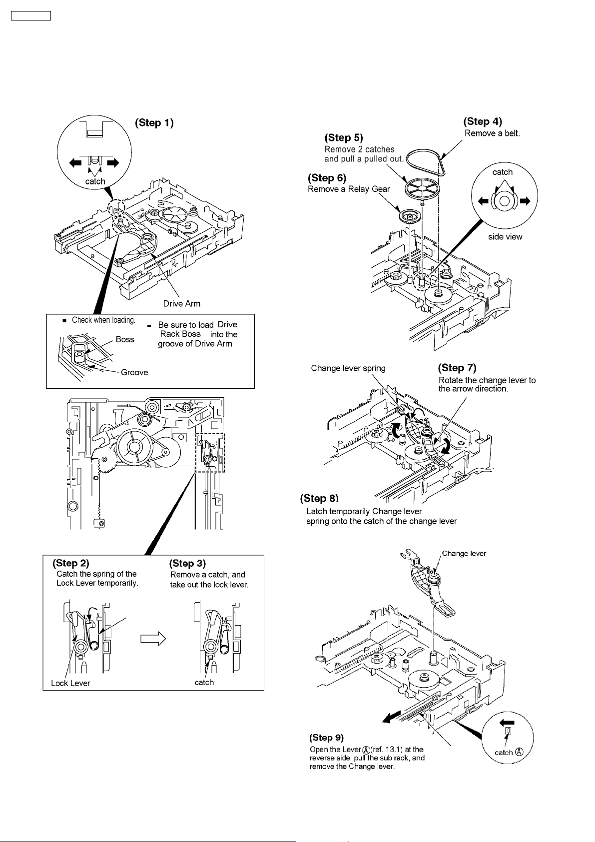
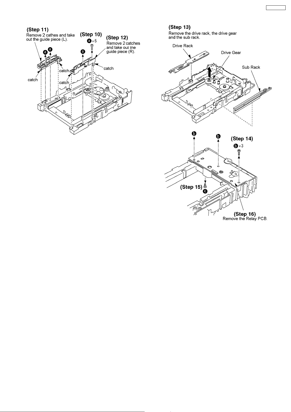
13.13.3. Disassembly of loading section.
· Follow the (Step 1) - (Step 4) of item 13.13.1 - Replacement of Traverse Unit
· Follow the (Step 1) - (Step 5) of item 13.13.2 - Replacement of Tray
28
SA-HT330EB
13.13.4. Replacement of Optical Pickup Unit
· Follow the (Step 1) - (Step 5) of item 13.13.1 - Replacement of Traverse Unit
· Follow the (Step 1) - (Step 5) of item 13.13.2 - Replacement of Tray
Step 1: Widen the catch, push the pin in.
29
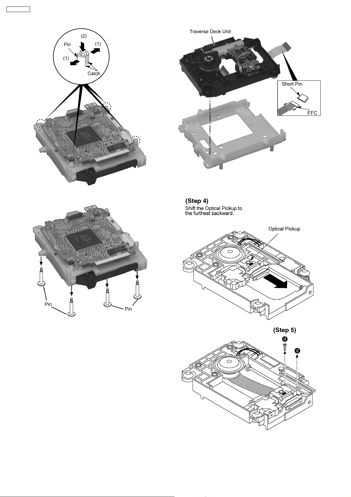
SA-HT330EB
Step 2: Remove 4 pins.
Note:
Insert a short pin into FFC of the optical pickup.
Step 3: Remove Traverse Unit.
30
 Loading...