

Panasonic SAHT-17 Service manual
Specification
nAMPLIFIER SECTION
RMS output power of each channel driven
(at 240 V for areas other than continental Europe)
10 % total harmonic distortion
1 kHz front CH
170 W per channel (6 Ω)
1 kHz surround CH
70 W per channel (4 Ω)
1 kHz center CH
260 W per channel (4 Ω)
100 Hz subwoofer CH
260 W per channel (4 Ω)
Total RMS output power 1000 W
DIN power output: Dolby Digital Mode
(at 240 V for areas other than continental Europe)
T.H.D. 1%
1 kHz front CH
100 W per channel (6 Ω)
1 kHz surround CH
45 W per channel (4 Ω)
1 kHz center CH
150 W per channel (4 Ω)
100 Hz subwoofer CH
160 W per channel (4 Ω)
Total DIN output power
DIN power output: Stereo Mode
(at 240 V for areas other than continental Europe)
T.H.D. 1%
1 kHz front CH
600 W
ORDER NO. MD0504177C2
AV Control Receiver
SA-HT17EP
SA-HT17EG
SA-HT17EB
Color
(S).......................Silver Type
90 W per channel (6 Ω)
100 Hz subwoofer CH
160 W per channel (4 Ω)
Total DIN output power
340 W
Total harmonic distortion
Half power at 1 kHz (Front CH) 0.1% (6 Ω)
Input sensitivity
DVD, DVR/VCR, TV, GAME/AUX
S/N at rated power (6 ΩΩΩΩ)
DVD, DVR/VCR, TV, GAME/AUX
Input impedance
DVD, DVR/VCR, TV, GAME/AUX 47 kΩ
Tone controls
BASS 50 Hz, +10 to -10 dB
TREBLE 20kHz,+10to-10dB
Digital input
OPTICAL 2
COAXIAL
nVIDEO SECTION
Output voltage at 1 V input (unbalanced) 1±0.1 Vp-p
Maximum input voltage
Input/output impedance 75 Ω
nFM TUNER SECTION
Frequency range 87.50-108.00 MHz
Sensitivity
S/N 30 dB 1.5 µV/ 75 Ω
S/N 26 dB 1.3 µV/ 75 Ω
S/N 20 dB 1.2 µV/ 75 Ω
IHF usable sensitivity (IHF’58) 1.5 µV/ 75 Ω
400 mV, IHF’66
75 dB (85 dB, IHF’66)
1.5 Vp-p
1
© 2005 Matsushita Electric Industrial Co. Ltd.. All
rights reserved. Unauthorized copying and
distribution is a violation of law.
SA-HT17EP / SA-HT17EG / SA-HT17EB
IHF 46 dB stereo quieting sensitivity 22 µV/ 75 Ω
Total harmonic distortion
MONO 0.2%
STEREO 0.3%
S/N
MONO 60 dB (71 dB, IHF)
STEREO 58 dB (65 dB, IHF)
Frequency response
20 Hz-15 kHz, +1 dB, -2 dB
Image rejection at 98 MHz
IF rejection at 98 MHz
Stereo separation
1 kHz
Antenna terminal 75 Ω (unbalanced)
nAM TUNER SECTION
Frequency range
522-1611 kHz (9 kHz steps)
530-1620 kHz (10 kHz steps)
Sensitivity
Selectivity (at 999 kHz)
nGENERAL
Power supply (For United Kingdom) AC 230-240 V, 50 Hz
Power supply (For Continental Europe)
Power consumption
(Main unit) 25 W
(Subwoofer) 390 W
Dimensions (W × H × D) (Main unit) 430 × 63 × 260 mm
Mass (Main unit)
Power consumption in standby mode:
AC 230 V, 50 Hz
40 dB
70 dB
40 dB
450 µV/m
35 dB
1.85 kg
1W
nSYSTEM
System: SC-HT17 (EP)
Main unit: SA-HT17 (EP)
Satellite Speaker: SB-HT17 (P)
Active Subwoofer: SB-WA17 (E)
System: SC-HT17 (EG)
Main unit: SA-HT17 (EG)
Satellite Speaker: SB-HT17 (P)
Active Subwoofer: SB-WA17 (E)
System: SC-HT17 (EB)
Main unit: SA-HT17 (EB)
Satellite Speaker: SB-HT17 (P)
Active Subwoofer: SB-WA17 (EB)
Speaker: SB-HT17 (P)
Front speakers: SB-FS930 (P-S1) x 2
Surround speakers: SB-FS880 (EG-S1) x 2
Center speaker: SB-PC930 (P-S1) x 1
Notes:
1. Specifications are subject to change without notice.
Mass and dimensions are approximate.
2. Total harmonic distortion is measured by the digital spectrum
analyzer.
For main unit
Marking sign is located on bottom of the unit.
* Manufactured under license from Dolby Laboratories.
“Dolby”, “Pro Logic” and the double-D symbol are trademarks of
Dolby Laboratories.
** Manufactured under license from Digital Theater System.
“DTS” and “DTS Digital Surround” are trademarks of Digital Theater
System.
CONTENTS
Page Page
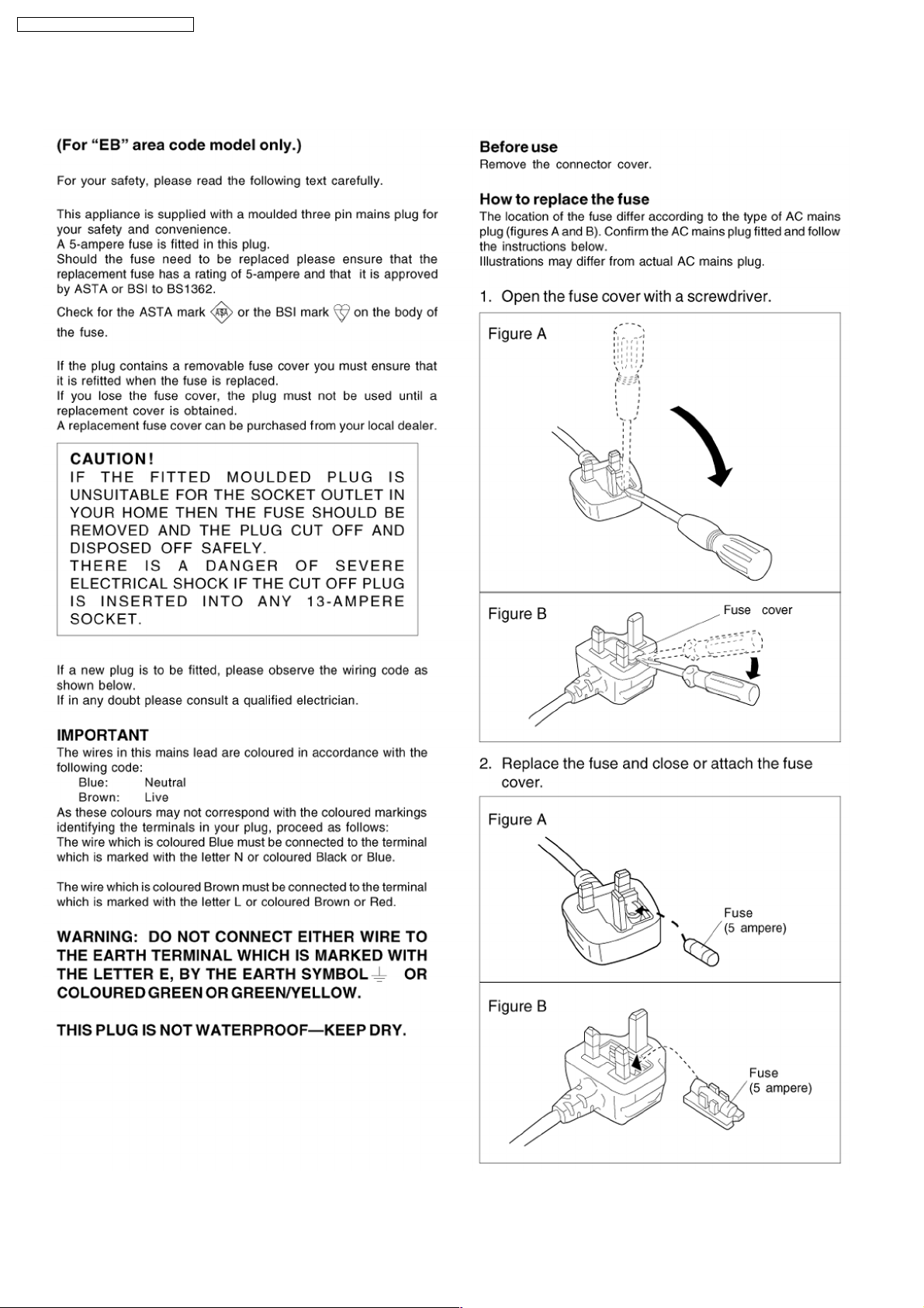
1 Caution for AC Mains Lead
2 Use of Active Subwoofer
2.1. Checking Player when Active Subwoofer is Used
2.2. Checking Main Unit Using Power Jig
3 Before Repair and Adjustment (Using Active Subwoofer Unit)
4 Safety Precautions
4.1. GENERAL GUIDELINES
5 Handling the Lead Solder
5.1. About lead free solder (PbF)
6 About the Protection Circuitry
7 Accessories
8 Operation Procedures
9 Remote Control
10 Assembling and disassembling
10.1. Disassembly flow chart
4
5
5
5
6
6
6
7
7
7
8
9
10
11
11
10.2. P.C.B. Positions
10.3. Disassembly of Top Cabinet
10.4. Disassembly of Rear Panel
10.5. Disassembly of Front Panel
10.6. Disassembly of Panel P.C.B.
10.7. Disassembly of Function P.C.B. & Volume P.C.B.
10.8. Disassembly of S-Video P.C.B.
10.9. Disassembly of DSP P.C.B.
10.10. Disassembly of Main P.C.B.
11 Service Position
11.1. Checking the DSP P.C.B. (Side A) & S-Video P.C.B.
11.2. Checking the Main P.C.B., Panel P.C.B., Function P.C.B.,
Volume P.C.B. & DSP P.C.B. (Side B)
12 Self Diagnosis Display Function
12.1. Automatically Displayed Error Codes
12.2. Error Code Display Details
2
12
13
13
13
14
14
15
15
16
17
17
17
18
18
18

SA-HT17EP / SA-HT17EG / SA-HT17EB
12.3. Activating Self Diagnosis Function (Doctor Mode) 18
12.4. Activating Self Diagnosis Function (Service Mode)
12.5. The Shutdown And Short Circuit Protection Detection
12.6. Returning to Normal Display
13 Block Diagram
14 Schematic Diagram
14.1. (A) DSP Circuit
14.2. (B) Main Circuit
14.3. (C) Panel Circuit
14.4. (D) Volume Circuit & (E) Function Circuit
14.5. (F) S-Video Circuit
15 Printed Circuit Board Diagram
15.1. (A) DSP P.C.B.
15.2. (B) Main P.C.B.
19
20
21
22
28
29
32
40
41
42
43
15.3. (C) Panel P.C.B. & (D) Volume P.C.B.
15.4. (E) Function P.C.B. & (F) S-Video P.C.B.
16 Wiring Connection Diagram
17 Type Illustration of ICエs, Transistors and Diodes
18 Terminal Function of IC
18.1. IC900 (C2CBHG000166): Microprocessor
19 Parts Location and Replacement Parts List
19.1. Cabinet Parts Location
19.2. Electrical Parts List
19.3. Packing Materials & Accessories Parts List
19.4. Packaging
43
45
47
49
50
52
53
53
54
55
57
64
65
3
SA-HT17EP / SA-HT17EG / SA-HT17EB
1 Caution for AC Mains Lead
4
SA-HT17EP / SA-HT17EG / SA-HT17EB
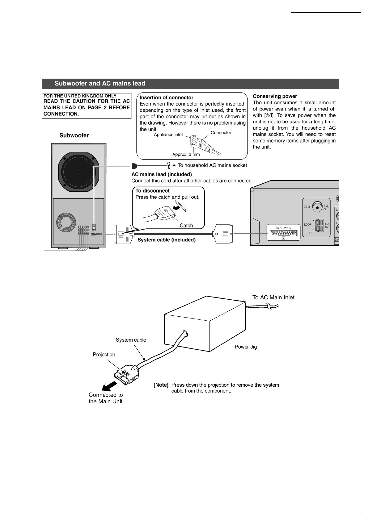
2 Use of Active Subwoofer
2.1. Checking Player when Active Subwoofer is Used
1. This unit uses the active subwoofer to supply the power of the component, and the active subwoofer should be connected to
the component to check operational conditions of the component.
2.2. Checking Main Unit Using Power Jig
If the active subwoofer is not available during time of repair to the unit, the following equipment could be used.
Jig product number
RFKZ0182 (110V , 127V, 220V, 230V - 240V for with voltage selector overseas domestic use).
5
SA-HT17EP / SA-HT17EG / SA-HT17EB
3 Before Repair and Adjustment (Using Active Subwoofer
Unit)
Disconnect AC power, discharge Power Supply Capacitors C546, C547, C548 & C549 through a 10Ω, 1W resistor to ground.
DO NOT SHORT-CIRCUIT DIRECTLY (with a screwdriver blade, for instance), as this may destroy solid state devices.
After repairs are completed, restore power gradually using a variac, to avoid overcurrent.
Current consumption at AC 230V, 50Hz in NO SIGNAL mode should be ~900 mA (For EP & EG only).
Current consumption at AC 230V - 240V, 50Hz in NO SIGNAL mode should be ~900 mA (For EB only).
4 Safety Precautions
4.1. GENERAL GUIDELINES
1. When servicing, observe the original lead dress. If a short circuit is found, replace all parts which have been overheated or
damaged by the short circuit.
2. After servicing, see to it that all the protective devices such as insulation barriers, insulation papers shields are properly
installed.
3. After servicing, make the following leakage current checks to prevent the customer from being exposed to shock hazards.
4.1.1. LEAKAGE CURRENT COLD CHECK
1. Unplug the AC cord and connect a jumper between the two prongs on the plug.
2. Measure the resistance value, with an ohmmeter, between the jumpered AC plug and each exposed metallic cabinet part on
the equipment such as screwheads, connectors, control shafts, etc. When the exposed metallic part has a return path to the
chassis, the reading should be between 1MΩand 5.2Ω.
When the exposed metal does not have a return path to the chassis, the reading must be
Fig. 1
.
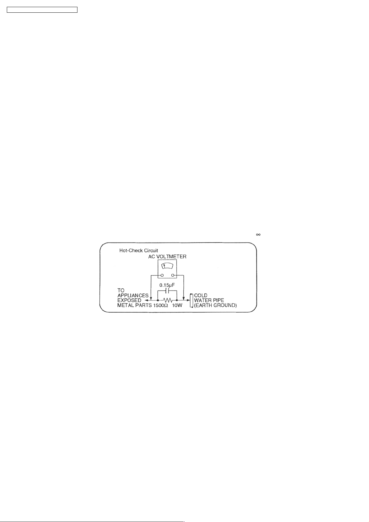
4.1.2. LEAKAGE CURRENT HOT CHECK (See Figure 1.)
1. Plug the AC cord directly into the AC outlet. Do not use an isolation transformer for this check.
2. Connect a 1.5kΩ, 10 watts resistor, in parallel with a 0.15µF capacitors, between each exposed metallic part on the set and a
good earth ground such as a water pipe, as shown in Figure 1.
3. Use an AC voltmeter, with 1000 ohms/volt or more sensitivity, to measure the potential across the resistor.
4. Check each exposed metallic part, and measure the voltage at each point.
5. Reverse the AC plug in the AC outlet and repeat each of the above measurements.
6. The potential at any point should not exceed 0.75 volts RMS. A leakage current tester (Simpson Model 229 or equivalent) may
be used to make the hot checks, leakage current must not exceed 1/2 milliamp. In case a measurement is outside of the limits
specified, there is a possibility of a shock hazard, and the equipment should be repaired and rechecked before it is returned to
the customer.
6

SA-HT17EP / SA-HT17EG / SA-HT17EB
5 Handling the Lead Solder
5.1. About lead free solder (PbF)
Distinction of PbF P.C.B. :
P.C.B.s (manufactured) using lead free solder will have a PbF stamp on the P.C.B.
Caution:
· Pb free solder has a higher melting point that standard solder; Typically the melting point is 50 - 70°F (30 - 40°C) higher.
Please use a high temperature soldering iron. In case of the soldering iron with temperature control, please set it to 700 ± 20°F
(370 ± 10°C).
· Pb free solder will tend to splash when heated too high (about 1100°F/600°C).
· W hen soldering or unsoldering, please completely remove all of the solder on the pins or solder area, and be sure to heat the
soldering points with the Pb free solder until it melts enough.
6 About the Protection Circuitry
The protection circuitry may have operated if either of the following conditions is noticed:
*No sound is heard when the power is supplied.
*Sound stops during a performance.
The functions of this circuitry is to prevent circuitry damage, for example, the positive and negative speaker connection wires are
“shorted”, or if speaker systems with an impedance less than the indicated rated impedance of this unit are used.
If this occurs, follow the procedure outlined below:
1. Press the STANDBY
2. Determine the cause of the problem and correct it.
3. Press the STANDBY
Note:
When the protection circuitry functions, the unit will not operate unless the STANDBY
then ON again.
/ON button, switch to STANDBY mode.
/ON button once again, supply the power.
/ON button is first switched STANDBY and
7
SA-HT17EP / SA-HT17EG / SA-HT17EB
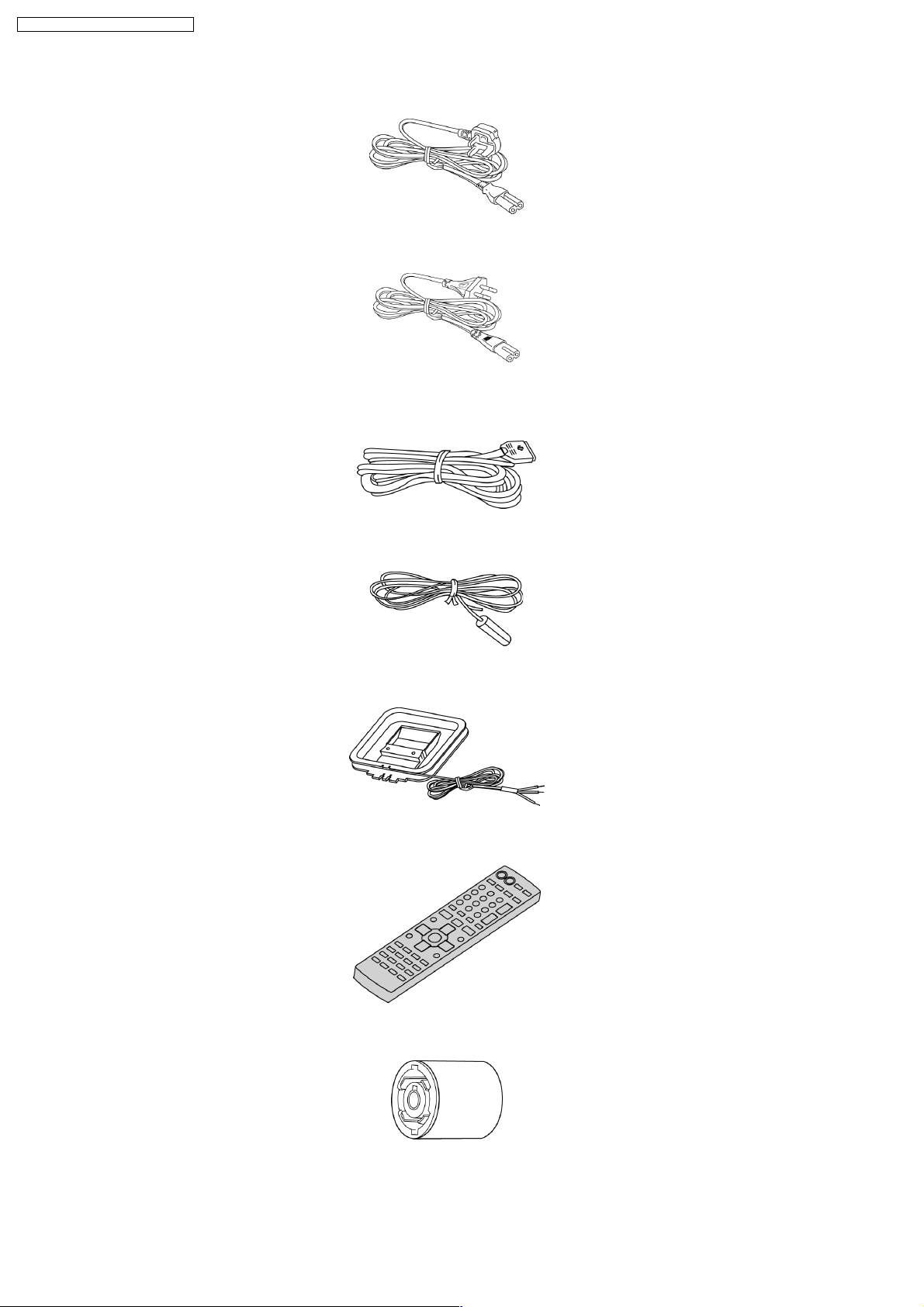
7 Accessories
AC cord (For EB only)
AC cord (For EG & EP
only)
System cable
FM indoor antenna
AM loop antenna
Remote control
Antenna plug
adapter (For EB
only)
8
8 Operation Procedures
SA-HT17EP / SA-HT17EG / SA-HT17EB
9
SA-HT17EP / SA-HT17EG / SA-HT17EB
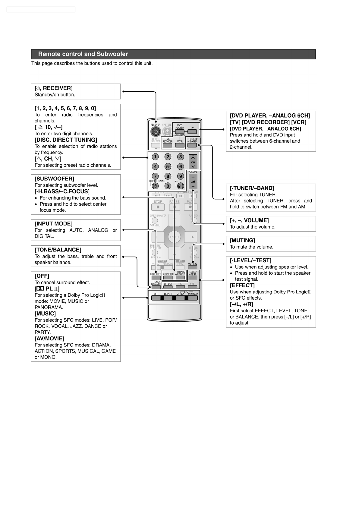
9 Remote Control
10
SA-HT17EP / SA-HT17EG / SA-HT17EB
10 Assembling and disassembling
“ATTENTION SERVICER”
Some chassis components may have sharp edges.
Be careful when disassembling and servicing.
1. This section describes procedures for checking the operation of the major printed circuit boards and replacing the main
components.
2. For reassembly after operation checks or replacement, reverse the respective procedures.
Special reassembly procedures are described only when required.
3. Select items from the following index when checks or replacement are required.
· Disassembly of Top Cabinet
· Disassembly of Rear Panel
· Disassembly of Front Panel
· Disassembly of Panel P.C.B.
· Disassembly of Function P.C.B. & Volume P.C.B.
· Disassembly of S-Video P.C.B.
· Disassembly of DSP P.C.B.
· Disassembly of Main P.C.B.
Warning:
This product uses a laser diode. Refer to caution statement Precaution of Laser Diode.
ACHTUNG:
Die Lasereinheit nicht zerlegen.
Die Lasereinheit darf nur gegen eine vom Hertsteller spezifizierte Einheit ausgetauscht werden.
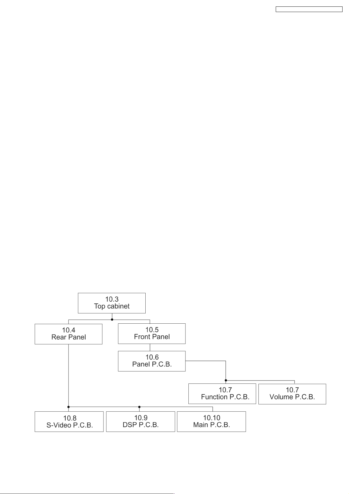
10.1. Disassembly flow chart
The following chart is the procedure for disassembling the casing and inside parts for internal inspection when carrying out the
servicing.
To assemble the unit, reverse the steps shown in the chart as below.
11
SA-HT17EP / SA-HT17EG / SA-HT17EB
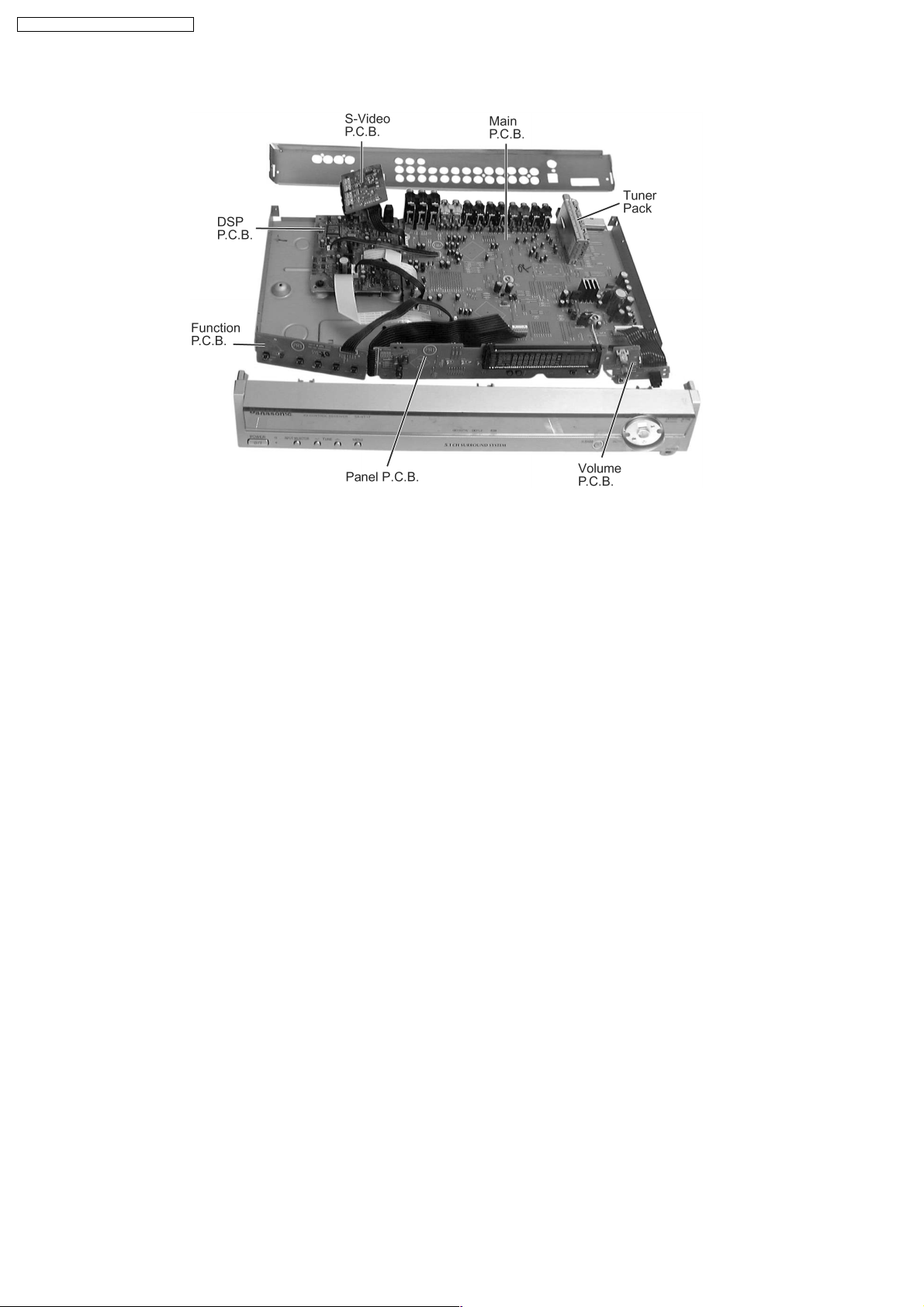
10.2. P.C.B. Positions
12
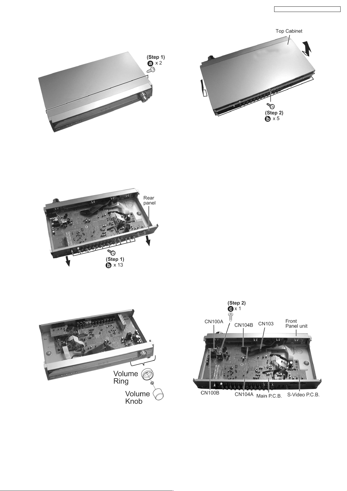
10.3. Disassembly of Top Cabinet
Step 1: Remove 2 screws.
Step 3 : Open and lift up the top cabinet in the direction of
Step 2 : Remove 5 screws at rear panel.
arrow shown.
10.4. Disassembly of Rear Panel
· Follow the (Step 1) - (Step 3) of item 10.3 - Disassembly of Top Cabinet
Step 1 : Remove 13 screws, pull rear panel forward in the arrow
shown.
SA-HT17EP / SA-HT17EG / SA-HT17EB
10.5. Disassembly of Front Panel
· Follow the (Step 1) - (Step 3) of item 10.3 - Disassembly of Top Cabinet
Step 1 : Remove the volume knob.
Step 2 : Remove 1 screw securing the grounding at Main
P.C.B..
Step 3 : Detach wire connectors (CN103, CN104A, CN104B,
CN100A & CN100B).
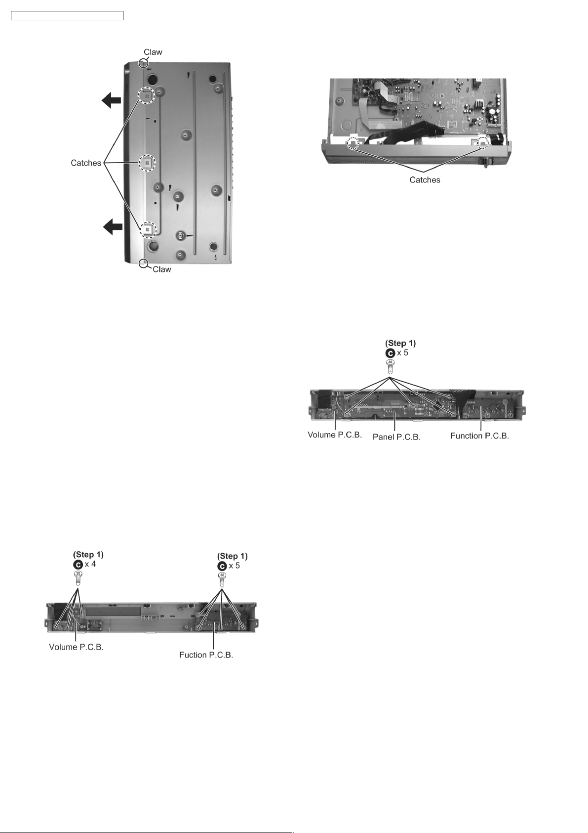
Step 4 : Release the claws & catches and push the front panel
as arrow shown.
13
SA-HT17EP / SA-HT17EG / SA-HT17EB
10.6. Disassembly of Panel P.C.B.
NOTE: When assembling the front panel unit, align the 2
catches properly.
· Follow the (Step 1) - (Step 3) of item 10.3 - Disassembly of Top Cabinet
· Follow the (Step 1) - (Step 4) of item 10.5 - Disassembly of Front Panel
Step 1 : Remove 5 screws at Panel P.C.B.
10.7. Disassembly of Function P.C.B. & Volume P.C.B.
· Follow the (Step 1) - (Step 3) of item 10.3 - Disassembly of Top Cabinet
· Follow the (Step 1) - (Step 4) of item 10.5 - Disassembly of Front Panel
· Follow the (Step 1) of item 10.6 - Disassembly of Panel P.C.B.
Step 1 : Remove 5 screws at Function P.C.B. and 4 screws at
Volume P.C.B.
14
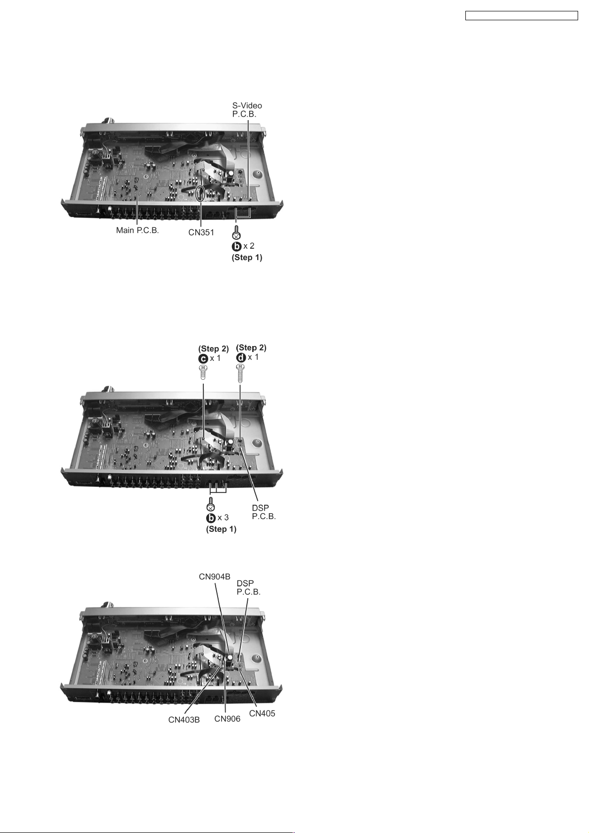
10.8. Disassembly of S-Video P.C.B.
· Follow the (Step 1) - (Step 3) of item 10.3 - Disassembly of Top Cabinet
Step 1 : Remove 2 screws at rear panel.
Step 2 : Disconnect connector CN351 at Main P.C.B.
10.9. Disassembly of DSP P.C.B.
SA-HT17EP / SA-HT17EG / SA-HT17EB
· Follow the (Step 1) - (Step 3) of item 10.3 - Disassembly of Top Cabinet
Step 1 : Remove 3 screws at rear panel.
Step 2 : Remove 2 screws at DSP P.C.B..
Step 3 : Disconnect 4 connectors, CN904 B, CN405, CN906 &
CN403B at DSP P.C.B.
15
SA-HT17EP / SA-HT17EG / SA-HT17EB
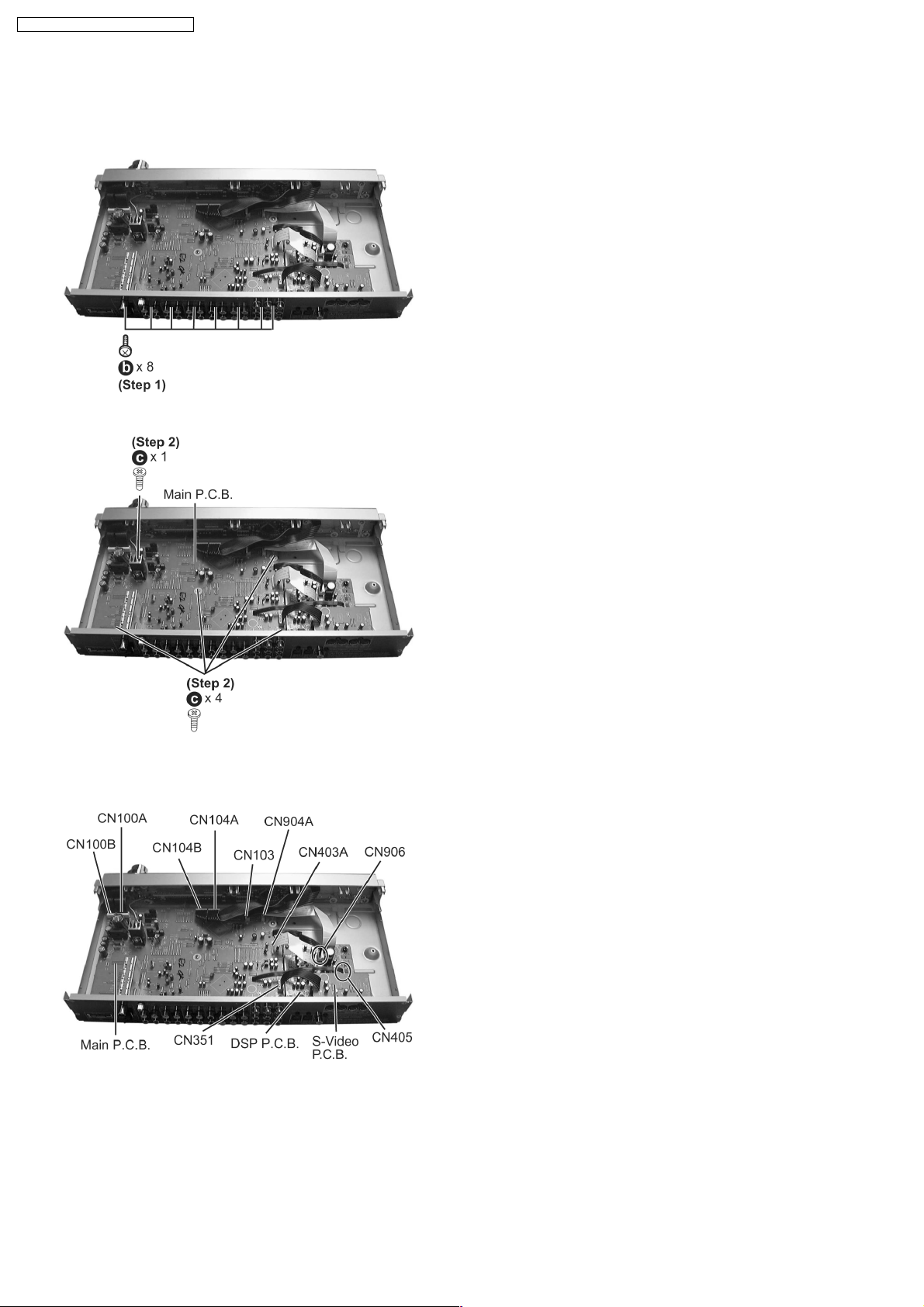
10.10. Disassembly of Main P.C.B.
· Follow the (Step 1) - (Step 3) of item 10.3 - Disassembly of Top Cabinet
Step 1 : Remove 8 screws at rear panel.
Step 2 : Remove 5 screws at Main P.C.B.
Step 3 : Remove 8 connectors at Main P.C.B. (CN100B,
CN100A, CN104 B, CN104A, CN103, CN904A, CN403 A &
CN351) & 2 connectors at DSP P.C.B. (CN906 & CN405 ).
16
SA-HT17EP / SA-HT17EG / SA-HT17EB
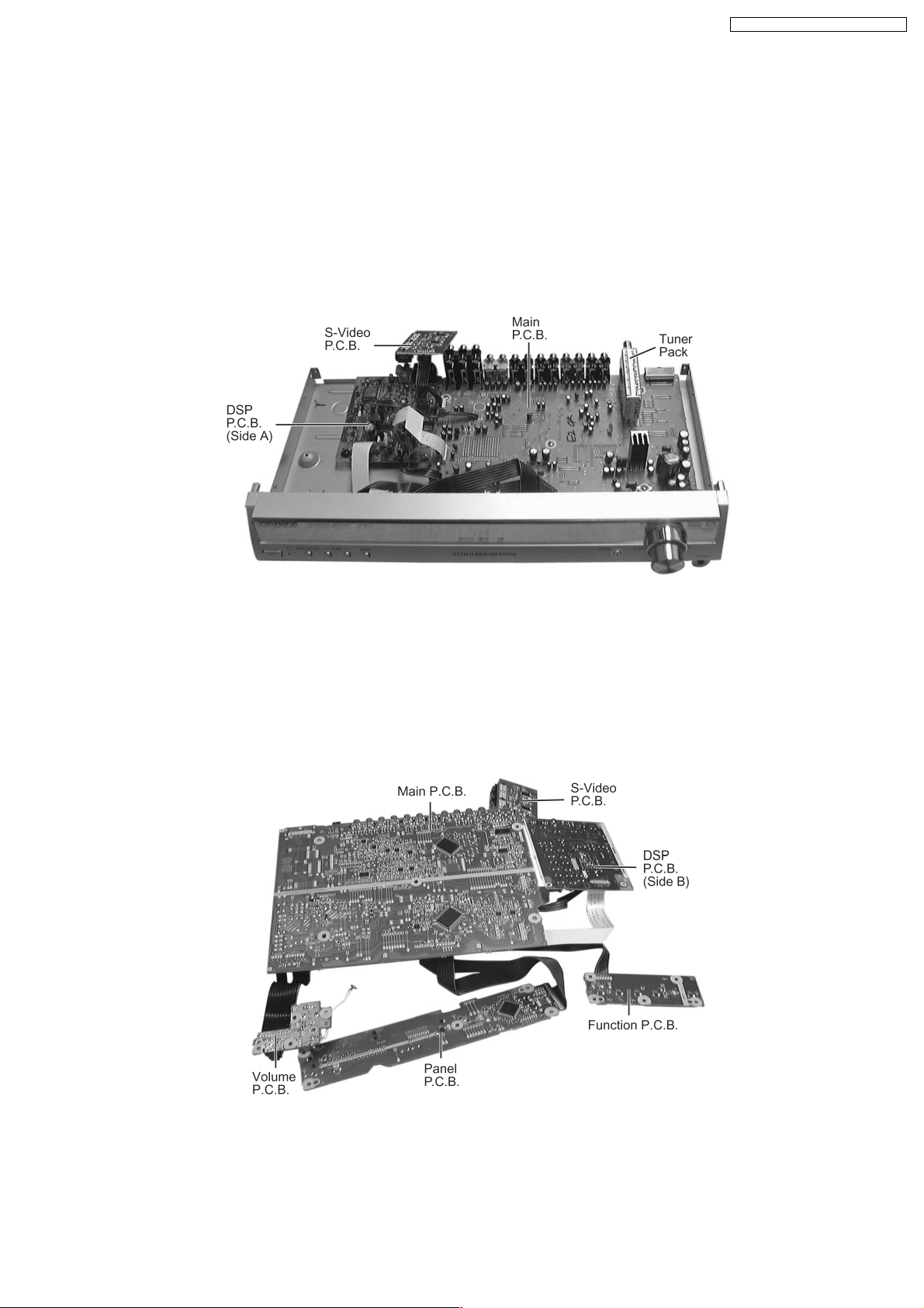
11 Service Position
Note:
Checking of all Major P.C.B. (S-Video P.C.B, Main P.C.B., DSP P.C.B., Volume P.C.B., Panel P.C.B. & Fuction P.C.B.) can be
carried out using below procedures.
For the disassembling procedure, see Section 10.
11.1. Checking the DSP P.C.B. (Side A) & S-Video P.C.B.
1. Remove Top Cabine t.
2. Remove Rear Panel.
3. Disassembly of S-Video P.C.B..
11.2. Checking the Main P.C.B., Panel P.C.B., Function P.C.B., Volume
P.C.B. & DSP P.C.B. (Side B)
1. Remove Top Cabine t.
2. Remove Rear Panel.
3. Disassembly of Front Panel.
4. Disassembly of Panel P.C.B., Function P.C.B., Volume P.C.B., S-Video P.C.B., Main P.C.B. & DSP P.C.B..
5. Flip the PCBs over (see as shown in picture below).
17
SA-HT17EP / SA-HT17EG / SA-HT17EB
12 Self Diagnosis Display Function
This unit is equipped with the self diagnosis display function, which alarms faulty operation with error code. Use this function during
servicing.
12.1. Automatically Displayed Error Codes
An error code automatically appears on the display (FXX) when faulty operation is detected. Refer to Fig. 12.1. For error codes,
refer to Section 12.2.
<Fig.12.1>
12.2. Error Code Display Details
Refer to the following table for error codes.
FL Display Symptom Cause and Remedy
OVERLOAD Speaker short, amplifier failure. Speaker short and failure in power
Humidity protection activated.
FAN LOCK The fan stops suddenly. Failure in fan or fan control circuits. Check
F70 Communication error between sub micro
processor and its peripheral LSI
F76 When the power is turned on, the unit
power autimatically turns off, the power
cannot be turned on.
amplifier, pre-amplifier circuits. Check for
faulty parts and replace with new parts if
necessary.
for faulty parts and replace with new parts
if necessary.
Failure sub-micro processor and its
peripherals LSI. Check for faulty aprts and
replace with new parts if necessary.
Failure in the power circuit system of the
unit. This may happen when the direct
current electricity is supplied to speaker
terminals. Check for the above and replace
with new parts if necessary.
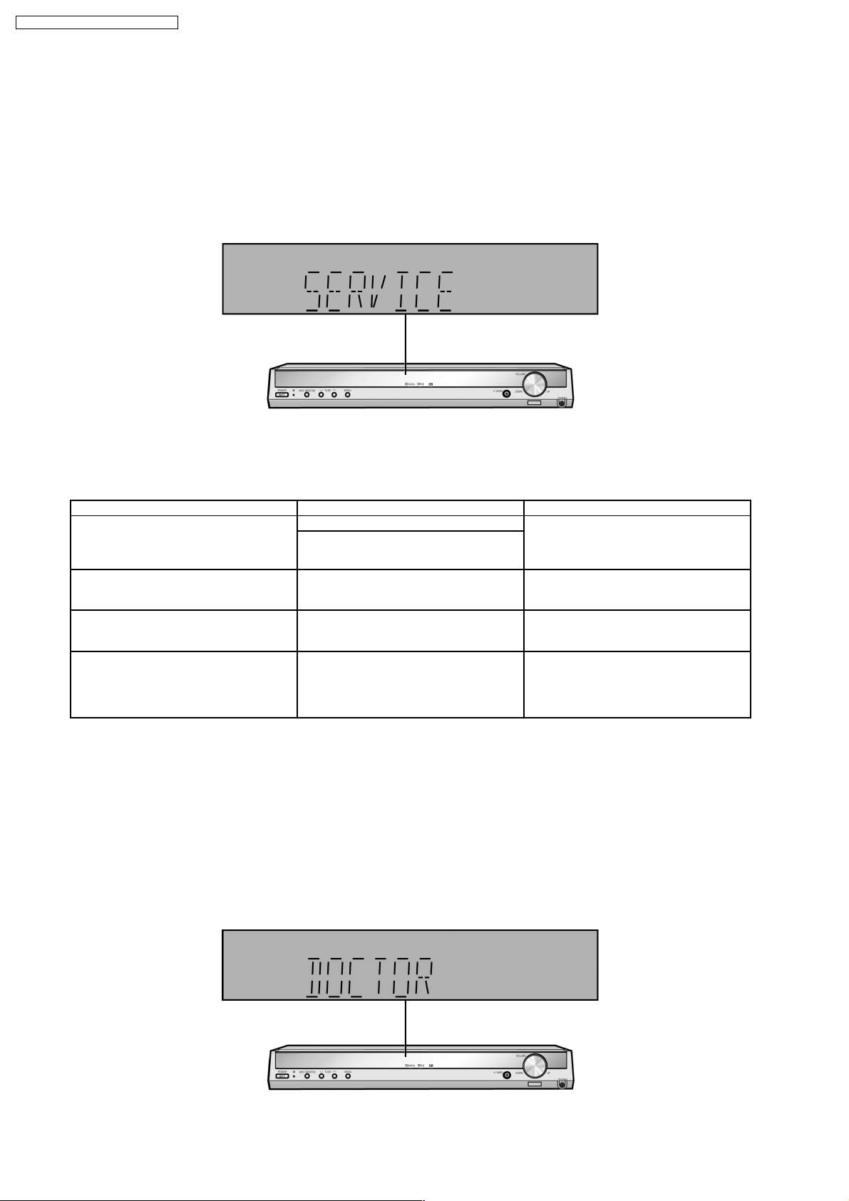
12.3. Activating Self Diagnosis Function (Doctor Mode)
This mode can be used during servicing.
1. With the following operation, the processing of this mode begins.
· Press and hold down the “INPUT SELECTOR” button and the “HARMONIC BASS” button, and then press the “POWER”
button at the same time.
* At this time, initialize all setting and set the following frequency to Tuner. FL display will display “_DOCTOR_” for 3
seconds.
E1: 99.7 MHz, E2/3: 93.40 MHz, JAPAN: 87.8 MHz
* The display is always blinked with 1Hz cycle to indicate that DOCTOR MODE is activated.
18
2. Normal function for all buttons on the unit.
3. Doctor mode function at some remote control codes as table below.
Remote Control Test Mode Function and settings
Selector Sound Mode Other setting Vol/Tone
CH 1 TUNER STEREO Frequency : FM min. *1) -48dB/0dB
CH 2 TUNER STEREO Frequency : FM max. -48dB/0dB
CH 3 TUNER STEREO FM 98.3 MHz. -18dB/0dB
CH 4 TUNER STEREO Frequency : AM min. -48dB/0dB
CH 5 TUNER STEREO Frequency : AM max. -48dB/0dB
CH 6 TUNER STEREO AM 765 kHz (9kHz/step) -18dB/0dB
CH 7 TUNER STEREO AM 770 kHz (10kHz/step) -18dB/0dB
CH 8 If the input selector is TUNER, auto tuning function is started to upward on current frequency.
CH 9 If the input selector is TUNER, auto tuning function is started to downward on current frequency.
CH 0 All indicators of FL are displayed. All LED are off.
Note: After this setting, only “POWER” button or “CHECKER COMMAND” code by the remote control
can be entered.
CH UP Check Main uP software Version.
CH DOWN Display [SUM_****]; **** is checksum. If no ROM correction, display [NO_EPRO M].
SUBWOOFER VCR (Analog) ---- - -18dB/0dB
MUTING DVD 6 CH ---- - -18dB/0dB
INPUT MODE GAME/ AUX STEREO Analog -18dB/0dB
SLEEP TV STEREO Analog -18dB/0dB
TONE/BAL DVD STEREO Analog -18dB/0dB
LEVEL DVR/VCR STEREO Analog -18dB/0dB
EFFECT DVD STEREO Digital (COAX) -48dB/0dB
STEREO TV STEREO Digital (OPT 1) -48dB/0dB
PL2 DVR/VCR STEREO Digital (OPT 2) -48dB/0dB
TEST No change SURROUND Scan the test noise output channel with
500ms intervals.
-/L GAME/ AUX STEREO Balance is set to leftmost. -18dB/0dB
+/R GAME/ AUX STEREO Balance is set to rightmost. -18dB/0dB
DIMMER If the input selector is TUNER in E2 mode, Display mode (PS/PTY) is changed.
SA-HT17EP / SA-HT17EG / SA-HT17EB
-18dB/0dB
* By the model setting, when there is not a function, ignore it. (ex. INPUT MODE in HT15 mode)
* Auto decode mode cannot activate in Doctor Mode.
*1) Memorize this frequency once in CH1 to 7 and recall it.
4. After enter the remote control code “DIRECT (TUNING)”, the message “OK” will appear for 0.2s second when each button is
press one by one.
5. Press “POWER” button on main unit or remote control to exit this mode.
12.4. Activating Self Diagnosis Function (Service Mode)
This mode is used for purpose of servicing.
1. With the following operation, the processing of this mode begins.
· Press and hold down the “HARMONIC BASS” button and the “TUNING DOWN” button, and then press the “POWER” button
at the same time.
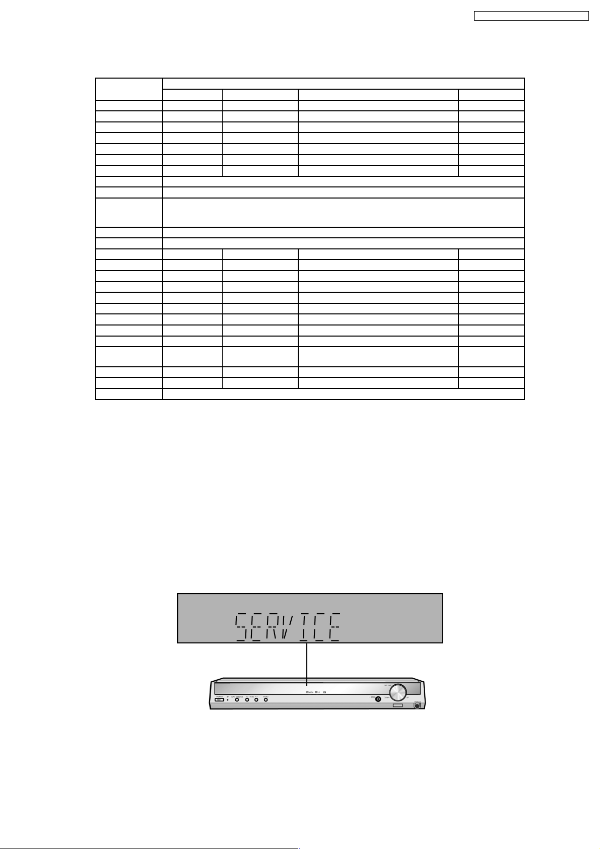
* At this time, initialize all setting and set the following frequency to Tuner. FL display will display “SERVICE” for 3 seconds.
2. To confirm the uP software Version: Press “TUNING DOWN” button on main unit, “MS085 **” is display ed.
19
SA-HT17EP / SA-HT17EG / SA-HT17EB
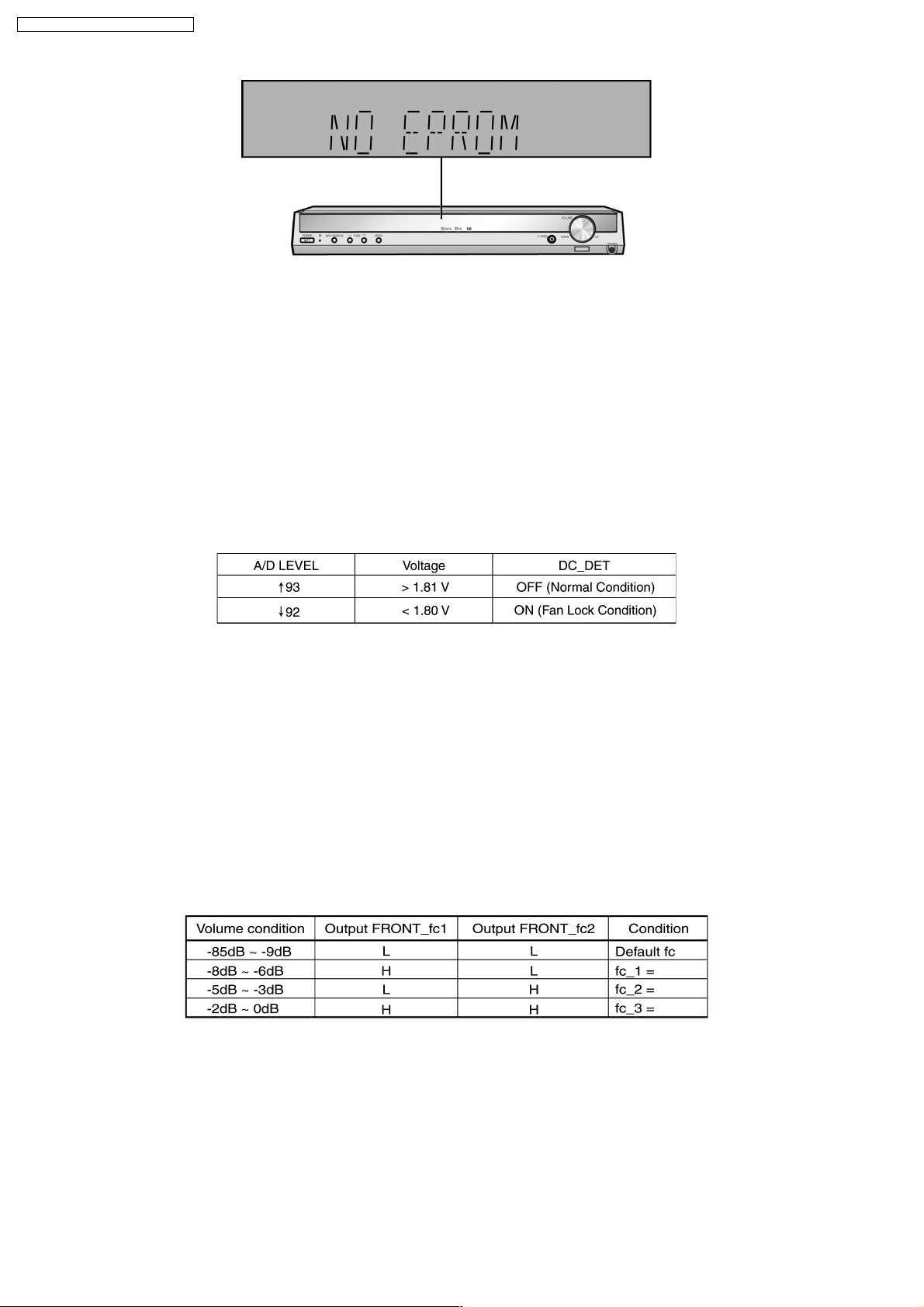
3. When [TUNE UP] is pressed, display “SUM ****”, “****” is the check sum of ROM for ROM correction.
If there is no EEPROM IC, “NO EPROM” is display ed.
4. Press “POWER” button on main unit or remote control to exit this mode.
12.5. The Shutdown And Short Circuit Protection Detection
It detects S_DET and DC_DET input port for malfunction.
1. S_DET Function (SHORT DETECTION)
It is to detect a short in the Power Supply. The detection of S_DET starts after 700ms after POWER ON.
After that, it is always detected for any malfunction.
Upon detection, the FLD display “F76” and the system is POWER OFF by setting POWER_REL AY port to OFF.
2. DC_DET Function
DC_DET (pin 94) on micon is used to detect FAN LOCK. During POWER ON, it will be ignored until ALL_MUTE is released.
Upon detection, FLD display “FAN LOCK” and MUTE_ALL will be set to ON. If any button is pressed, it is made to scroll error
message “SWITCH OFF POWER”. After Power Off and On,this condition is reset, and DC_DET will resume detection of error.
It also sets MUTE_SW to ON, to switch OFF the power amplifier.
3. FREQUENCY LIMITER
Due to surround speaker change from 6.5 cm to 8 cm. We have to limited certain output level to certain FOR FRONT L/R
channel and SURROUND L/R cut off frequency in order to avoid speaker noise.
4 ports are used for this purpose. 2 ports are used for front L/R channel, 2 ports for surround L/R channel.
Front Left/ Right Freq limiter (Port Name: FRONT_fc1[pin49], FRONT_fc2[pin50])
Surround Left/ Right Freq limiter (Port Name: SURR_fc1[pi n47], SURR_fc2[pin48])
For FRONT L/R
For SURROUND L/R
20
 Loading...