

Panasonic SAGX690 User Manual
80k
SM
Technics'
AV control stereo receiver
SA-GX690
SA-GX490/SA-GX390
Operating Instructions
Dear Customer
Thank you for purchasing this Technics product.
For optimum performance and safety, please read
these instructions carefully.
These operating instructions are applicable to models
SA-GX690, SA-GX490 and SA-GX390.
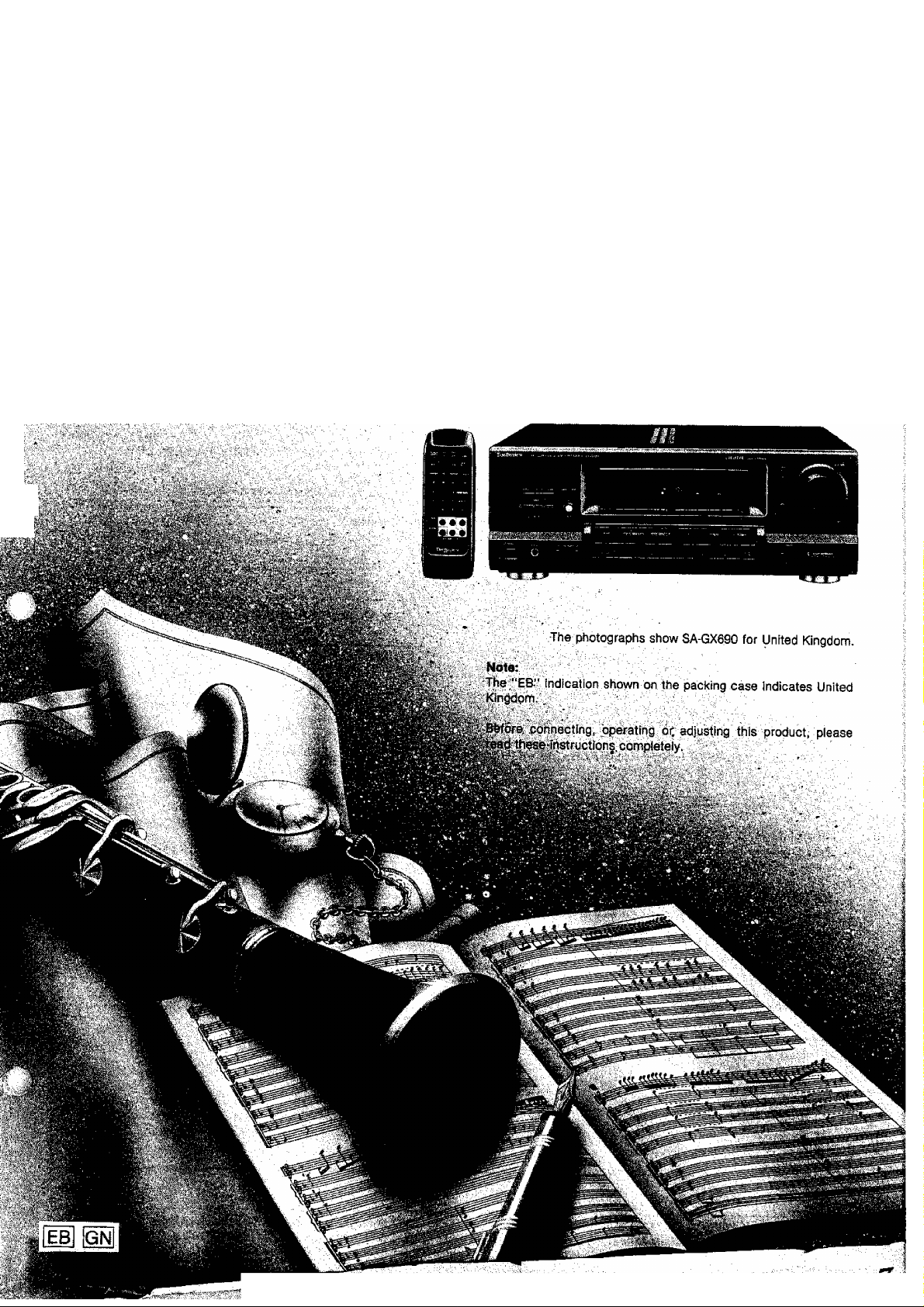
These operating instructions, however, are intended primarily for
modei SA-GX690.
Caution for AC mains iead
(For United Kingdom)
(“EB” area code mode) only)
For your safety, please read the following text carefully.
This appliance is supplied with a moulded three pin mains
plug for your safety and convenience.
A 5-ampere fuse is fitted in this plug.
Should the fuse need to be replaced please ensure that the
replacement fuse has a rating of 5-ampere and that it is ap
proved by ASTA or BSI to BS1362.
Check for the ASTA mark<^ or the BSI mark^ on the body
of the fuse.
If the plug contains a removable fuse cover you must ensure
that it is refitted when the fuse is replaced.
If you lose the fuse cover the plug must not be used until a
replacement cover is obtained.
A replacement fuse cover can be purchased from your
local dealer.
WARNING: DO NOT CONNECT EITHER WIRE TO THE
EARTH TERMINAL WHICH IS MARKED WITH THE LET
TER E, BY THE EARTH SYMBOL i OR COLOURED
GREEN OR QREEN/YELLOW.
THIS PLUG IS NOT WATERPROOF-KEEP DRY.
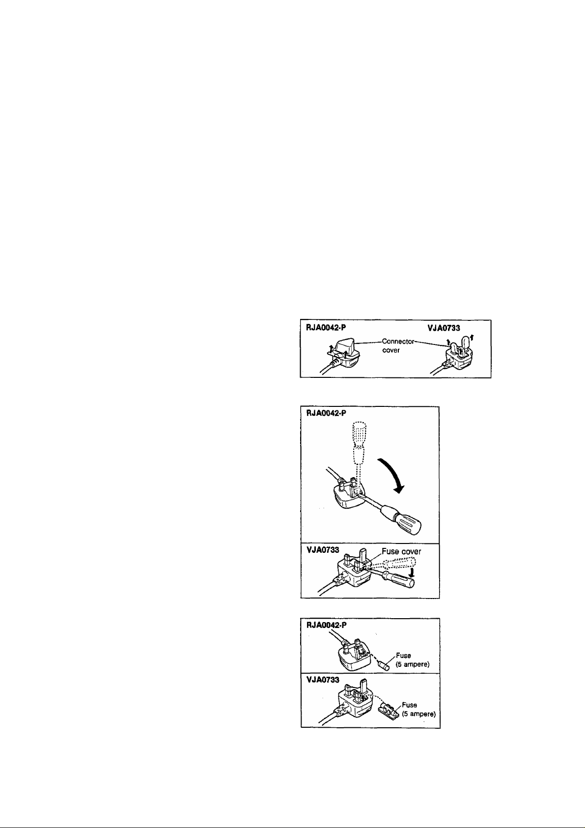
Before use
Remove the connector cover as follows.
How to replace the fuse
1. Open the fuse cover with a screwdriver.
.
CAUTION!
IF THE FITTED MOULDED PLUG IS UNSUITABLE FOR
THE SOCKET OUTLET IN YOUR HOME THEN THE FUSE
SHOULD BE REMOVED AND THE PLUG CUT OFF AND
DISPOSED OF SAFELY.
THERE IS A DANGER OF SEVERE ELECTRICAL SHOCK IF
THE CUT OFF PLUG IS INSERTED INTO ANY 13-AMPERE
SOCKET.
If a new plug is to be fitted please observe the wiring code as
shown below.
if in any doubt please consult a qualified electrician.
IMPORTANT
The wires In this mains lead are coloured in accordance with
the following code:
Blue: Neutral, Brown; Live.
As these colours may not correspond with the coloured mark
ings identifying the terminals in your plug', proceed as foliows;
The wire which is coloured Blue must be connected to the ter
minal which is marked with the letter N or coloured Black or
Blue.
The wire which is coloured Brown must be connected to the
terminal which is marked with the tetter L or coloured Brown
or Red.
2. Replace the fuse and close or attach the fuse cover.
(For Australia and N.Z.)
THIS TUNER/RECEIVER IS CAPABLE OF RECEIVING THE NEW AM STEREO BROADCASTS FROM THE AM BAND RADIO STATIONS.
HOWEVER LIKE MANY TUNERS AND RECEIVERS CURRENTLY AVAJLABLE ON THE MARKET IT WILL REPRODUCE THIS AM STEREO
SIGNAL ONLY IN AM MONO, WHICH, IN EFFECT. IS OF NO LESSER QUALITY THAN YOUR EXISTING AM MONO TUNERyRECElVER.
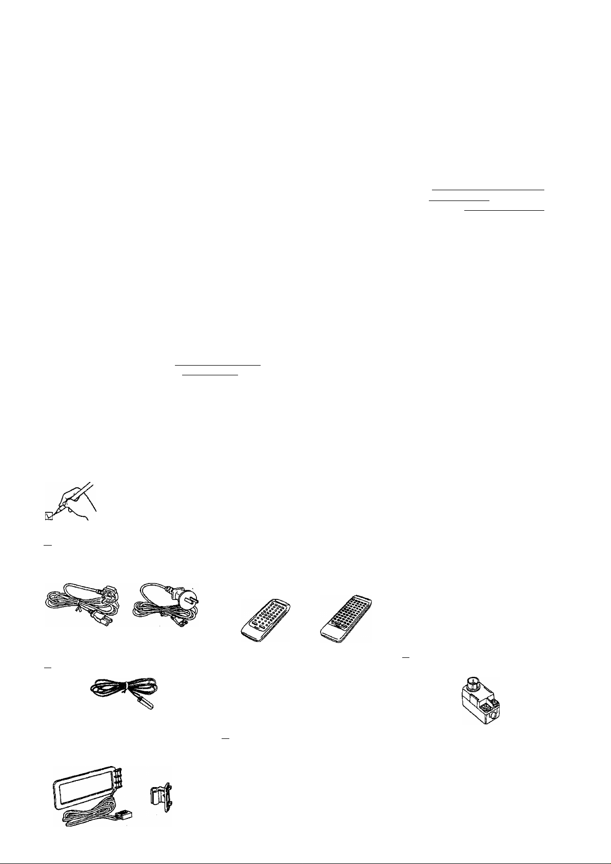
Table of contents
Before use
Accessories.................................................................. 3
Suggestions for safety
Front panel controls
................................................
....................................................
ConnectioDS
Equipment connections
Antenna connections
Speaker connections...................................................10
..............................................
..................................................
Listening
Basic operations.........................................................12
If sound output stops during use or if you are unsure
what to do........................................................................ 13
To adjust the tone quaiity
To mute the sound level
To adjust the sound balance
To emphasize low frequency sound ig«eiMa!i!l!l!iW
To listen through headphones......................................... 13
Listening to radio broadcasts
Direct access tuning........................................................ 14
Sequential tuning............................................................. 14
Preset tuning................................................................... 15
................................................
..................................................
.........
...................................
...................................
........
13
13
13
14
4
5
6
8
13
Adjusting the sound field
Enjoying sound with DOLBY PRO LOGIC
SURROUND................................................................... 17
3 STEREO...................................................................... 17
Setting the center mode
Adjusting speaker output level....................................... 18
Adjusting the delay time lefiBekirftligBiBI
Enjoying with SURROUND or 3 STEREO
Enjoying sound with SFC 20
Adjusting field of sound
.................................................
..................................................
...............
.......................
....................
17
17
19
19
20
Recording
Making a recording....................................................21
Recording on the tape deck........................................... 21
Recording on the VCR (VCR 1)..................................... 21
When there seems to be a problem
About the HELP function...........................................22
Troubleshooting guide...............................................23
Reference
Technical specifications
.........................
Back cover
Accessories
Please check and identify the supplied
accessories
I [ AC power supply cord
(For United Kingdom) (ForAiislraBaandNZ)
{VJA0733orRJA0042-P) (RJA0036-K)
[ I FM indoor antenna (RSA0007).. 1 pc.
AM loop antenna set (RSAOOIO)
□
• AM loop antenna
• AM antenna holder
• Screw
.....................................
.................
....................
.................
1 pc, Q Remote control transmitter
1 pc.
1 pc.
1 pc.
..............
For SA-GX690/
SA-GX490/
SA-GX390
(RAK-SA179XH)
For details on remote control transmitter
operation, refer to “How to use the remote
control transmitter” in the separate
booklet.
[ I Batteries
(UM-4, "AAA”, R03)
c
For SA-GX690
(For Australia
and N.Z.)
(RAK-SA603MH)
J
1 pc. Q] Attachment plug (SJP9009).
2 pcs.
(United Kingdom only)
I I Antenna plug (RFE0014)..
(Australia and N.Z. only)
1 pc.
1 pc.
Suggestions for safety
Placement
Avoid placing the unit in areas of:
• direct sunlight
• high temperature
• high humidity
• excessive vibration
• uneven surfaces (Piace the unit on a flat level surface.)
Such conditions might damage the cabinet and/or other compo
nent parts and thereby shorten the unit’s service life.
Ventilation
• Race the unit in a vrell ventilated position at least 10 cms away
from wall surfaces etc.
• Ensure that curtains and similar materials do not obstruct the
ventilation holes.
Stacking
Never place heavy items on top of the unit or the power cord.
Voltage
• It is very dangerous to use an AC power source of high voltage
such as for an air conditioner.
A fire might be caused by such a connection.
• A DC power source can not be used.
Be sure to check the power source carefully, especially on a
ship or other place where DC is used.
Power cord protection
• Avoid cuts, scratches or poor connection of the AC mains cord,
as this may result in fire or electric shock hazard.
Excessive bending, pulling or slicing of the cord should also be
avoided.
• Do not pull on the cord when you are disconnecting the power,
as this could cause an electric shock. Grasp the plug firmly
when you disconnect the power supply,
• Never touch the plug with wet hands or a serious electric shock
could result.
Foreign materials
• Ensure that no foreign objects, such as needles, coins,
screwdrivers etc., accidentally fall into the unit or through the
ventilation holes.
Otherwise, a serious eiectric shock or malfunction could occur,
• Be extremely careful about spilling water or liquid on/into the
unit, as a fire or electric shock could occur.
(Disconnect the power plug and contact your dealer immediate
ly if this occurs.)
• Avoid spraying insecticides onto the unit as they contain flam
mable gases which can be ignited.
• In secticides, alcohol, paint thinner and similar chemicals
should never be used to clean the unit as they can cause flaking
or cloudiness to the cabinet finish.
Maintenance
Clean the cabinet, panel and controls with a soft cloth lightly
moistened with mild detergent solution.
Do not use any type of abrasive pad, scouring powder or solvent
such as alcohol or benzine.
Service
' Never attempt to repair, disassemble or reconstruct the unit if
there seems to be a problem.
A serious eiectric shock could result if you ignore this precau
tionary measure.
* If a problem occurs during operation (the sound is interrupted,
indicators fail to illuminate, smoke is detected, etc) contact
your dealer or Authorized Service Center immediately.
* Disconnect the power supply if the unit will not be used for a
long time. Otherwise the operation life could be shortened.
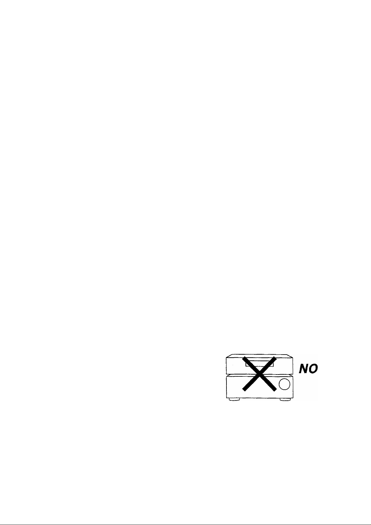
CAUTION
Do not place a tape deck or CD player on top of this unit.
Heat radiated from the top of this unit may cause damage to
the tape or CD software.
■y . ■ v>. ^ ,•
; ' -i"■■■■;;■■ "r ; •
■ * S / N • '
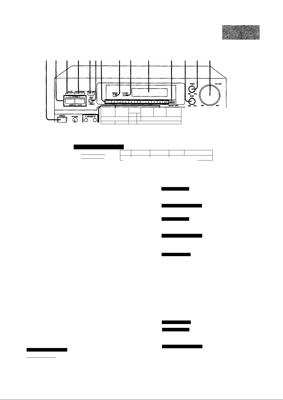
CD ® ® (5) ®i(6)(7) (8) (|)
vcn wio coc o
ves t
orrm—iSm m
L-v-l.
® ® ®® ® @ ®)(gl
For SA-GX490/GX390
-COLBY PftOLOGIC-
iSURBpUHptsSTpEOl
No. Name
Power »STANDBY 6 /ON” switch
(POWER, STANDBY 6/ON) 12
Press to switch the unit from on to standby mode or vice ver
sa. In standby mode, the unit is still consuming a small
amount of power.
Tuning control (TUNING) 14
Band select button (BAND) 14
0 FM mode select button
(FM AUTO/MONO) 14
Direct tuning button
(DIRECT TUNING)
Help/reset button (-HELP -RESET) 13J2
® Numeric buttons (1-0, ^10)
Remote control signal receptor “STANDBY” Indicator ^
When the unit is connected to the AC mains supply, this in
dicator tights up in standby mode and goes out when the unit
is turned on.
Display
(Q) Memory button (MEMORY) 15,16
@ Bass control (BASS) 13
Treble control (TREBLE) 13
(Q) Volume control (VOLUME) 12
Headphone jack (PHONES)
For SA-GX690/GX490
Speaker select buttons (SPEAKERS)
Speaker button (SPEAKERS)
(Q) Input select buttons
12,19,21,22
a ZL
lL
Ref. page
14,16
IBT r*
TEST CENTER
. - i +
14
13
12
12
(fi) ® (® ®
CO nme n
El ■ U RWH UI biR vctto tAi ic -la umn t
I 1 I .1 . 1
SURROUND cematMOoe MUTING
- 1 ^
No. Name
For SA-GX690
DOLBY PRO LOGIC/SFC OFF ON button
(OFF/ON) 19^0
For SA-GX490/GX390
Surround button (SURROUND)
For SA-GX690
DOLBY PRO LOGIC mode select button
(PRO LOGIC) 17,18,19
For SA-GX490/GX390
3 stereo button (3 STEREO)
SFC mode select button (SFC)
SA-GX690 only
Test signal button (TEST)
Tape monitor button
(TAPE MONITOR)
Center level adjust button (CENTER) 18,20
Surround level adjust button
(SURROUND)
Center mode select button
(CENTER MODE)
Delay time adjust button (DELAY TIME)
SA-GX690 only
For SA GX690
Muting/loudness button
(-MUTING -LOUDNESS)
For SA-GX490/GX390
Muting button (MUTING)
Balance control (BALANCE)
PMM O
L ■ J
Ref. page
17,18,19
17,18,19
20
18
12,21
18,20
17
19
13
13
13
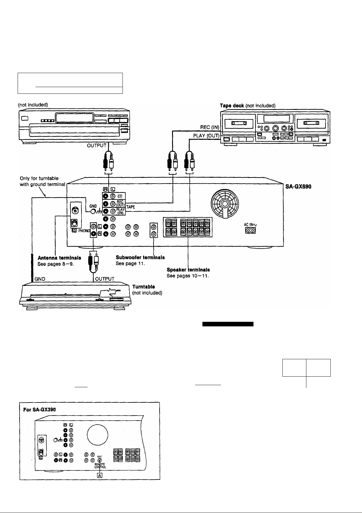
Connecting audio equipment
Stereo connection cable (not included)
White
(L) <^~TnmiiEK
(fl) "
Red
CD changer (or CD player)
ES3I9
Do not place books, etc., on top of this unit or block the heat
radiation vents in any way.
For SA-GX490
IS CD
0®
o®
0/^0 ®
0®
®00® ® ®
o@o®
® ® ®
MOtL ,
B
HTRQI.I
For SA GX490/GX390
0
“REMOTE CONTROL OUT” terminal
CD player
(or CD changer)
(not included)
REMCOTE
)
1-J
T
OUT
REMOTE
yCDNTRQI^
Connection cables for remote control
Tape deck
(not included)
REMOTE mNTROL
IN Q Q OUT
(not included)
Connect the connection cable for remote control to a
Technics tape deck and/or CO changer (or CD player) which
has the appropriate remote control terminal as shown
above.
If a tape deck is not being used, the CD changer (or CD
player) can be connected directly (dotted line).
For a tape deck and/or CD changer (or CD player) with a
remote control sensor, this connection is not necessary.
1
_
1
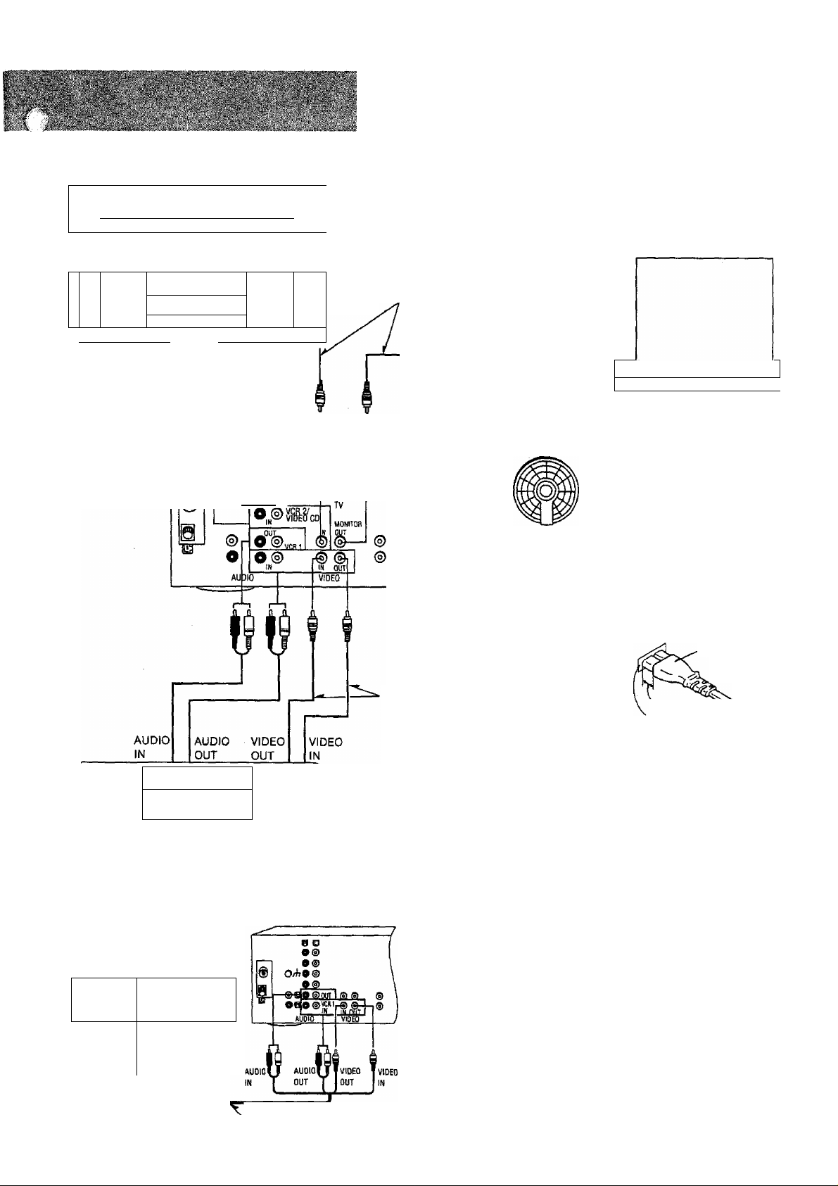
Connecting video equipment
Stereo connection cable (not included)
White (L) cnniinPs| Amir~
Red
(R)
Second VCR (for playback oniy)
or video CD changer (not included)
□
III. J°
—
Tzzzd
--------
o^iÙÒOoaoi
AUDIO
OUT
---VIDEO
OUT
>
CZI
•~ . /-.' „ ■ 'i s'' '., _ ■ l-,..jc'j.' '» i./* . ,- .*■*. ‘ '"'ij',“. ■''.'.”>.J ‘-'i^,'"''- '■
TV
(not included)
Video connection cables
(not included)
VIDEO
IN
_____
e ©
o®
. o®
O/hO ®
Video connection cables
(not included)
alF
To connect a video deck with 2t pin scart ter
minal
VCR (not included)
AV
IN
L_|
~1
!°
PçÜQr'jnoan
VCR
(not included)
This unit
iiÜi
Cooling fan
The cooling fan operates at high
power output levels only.
AC power supply cord'
(included)
Connect this cord after
ail other cables and
cords are connected.
(United Kingdom oniy)
BE SURE TO READ THE CAUTION FOR THE AC
POWER SUPPLY CORD ON PAGE 2 BEFORE CON
NECTION.
ACIN^v
SA-OX690
(United Kingdom only)
Connector,
Approx. 6 mm
'^pliance inlet
Even when the connector is
perfectly inserted, the front
part of the connector jut out as
shown in the drawing.
However there is no problem us
ing the unit.
y
•■ej
Household
AC outlet
21 pin scart cable (not included)
''r'K'
' /*- ’^ \ fc /»'V \í « j-'
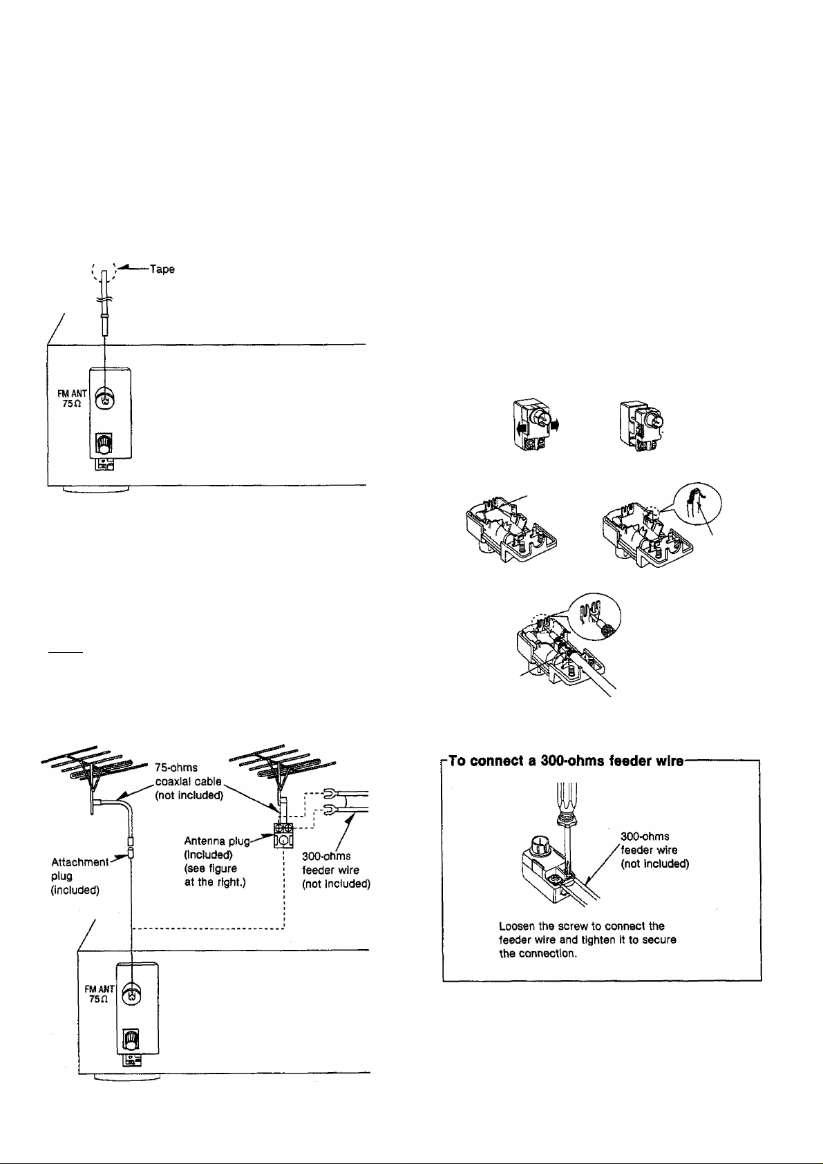
FM indoor antenna (included)
This antenna is normally sufficient for reception of FM broad
casts.
FM indoor antenna
(included)
FM outdoor antenna (not included)
(For Australia and N.Z.)
M How to use the antenna plug (Included)
Two types of wire are most commonly used for connection from
the antenna; 300-ohms parallel feeder wire or 75-ohms coaxial
cable, For best resistance to outside interference, the use of 75ohms coaxial cable is suggested.
To connect a 75*ohms coaxial cable-
CD Remove a piece of the outer vinyl insulator.
20 mm 10 mm
(D Remove the cover while pulling the tabs.
If the tabs are pulled too hard, the casing may be damag
ed.
Remove the lead wire and clamp It with the plastic bar.
,Lead wire
Plastic bar
The outdoor antenna should be used when using the main unit in
mountainous areas or in spaces enclosed by reinforced concrete
where the FM indoor antenna (included) does not provide
satisfactory reception.
t'StlllSI
An outdoor antenna should be installed by a qualified technician
only.
(For United Kingdom)
FM outdoor antenna
(not included)
(For Australia and N.Z.)
FM outdoor antenna
(not included)
(D Install the coaxial cable.
Clamp the cable
conductor, and wind It
on so that it doesn’t
contact anything else.
Press down
with pliers.
d) Attach the cover.
5
 Loading...