

Panasonic SADK-20-GN Service manual

ORDER NO. MD0206154C3
DVD Stereo System
SA-DK20GN
Colour
(S)... Silver Type
TAPE SECTION :
SPECIFICATIONS
AR2 MECHANISM SERIES
Specifications
1

AMPLIFIER SECTION
RMS power output
10% THD, both channels driven
75 Hz
Subwoofer
150 W (4 )
1 kHz
Front
Center
Surround
45 W per ch (6 )
70 W (8 )
40 W per ch (8 )
Total power in stereo mode
(Front and Subwoofer)
240 W
Total power in Home Theater mode
390 W
Input sensitivity
AUX
250 mV
Input Impedance
AUX
10 k
FM TUNER SECTION
Frequency range
87.50 - 108.00 MHz (50
kHz steps)
Sensitivity
S/N 26 dB
1.8 V (IHF)
1.5 V
Antenna terminal(s) 75 (unbalanced)
AM TUNER SECTION
Frequency range
522 - 1629 kHz (9 kHz
steps)
Sensitivity
S/N 20 dB (at 999 kHz)
500 V/m
CASSETTE DECK
SECTION
Track system
4 track, 2 channel
Heads
Record/playback
Erasure
Motor
Recording system
Erasing system
Tape speed
Solid permalloy head
Double gap ferrite head
DC servo motor
AC bias 100 kHz
AC erase 100 kHz
4.8 cm/s (1 7/8 ips)
Overall frequency response (+3 dB, -6 dB at DECK
OUT)
NORMAL (TYPE I)
HIGH (TYPE II)
S/N ratio
35 Hz - 14 kHz
35 Hz - 14 kHz
50 dB (A weighted)
2

Wow and flutter
Fast forward and rewind
Approx. 120 seconds with
0.18 % (WRMS)
time
C-60 cassette tape
Disc SECTION
Disc
DVD-Video
8 cm/12 cm single-sided, single-layer
8 cm/12 cm single-sided, double-layer
8 cm/12 cm double-sided, double-layer
(One layer per side)
Video CD/CD 8 cm/12 cm (CD-R/RW)
Video
Signal system NTSC/PAL
(depending on disc
format)
Output level
Composite video 1 Vp-p (75 )
S-Video Y 1 Vp-p (75 )
S-Video C 0.300 Vp-p (75 )(PAL)
0.286 Vp-p (75 )(NTSC)
Audio
Sampling frequency
CD
DVD
Decoding
Wow and flutter
D/A converter
16/20/24 bit linear
Below measurable limit
Delta-sigma DAC)
44.1 kHz
48kHz/96 kHz
Pick up
Beam source
Semiconductor Laser
Wavelength
DVD 658 nm
VCD/CD 790 nm
GENERAL
Power supply
Power consumption
AC 230 - 240 V, 50Hz
186 W
Power consumption in standby mode
0.6 W
Dimensions (W x H x D)
Mass
215.4 X 315 X 350 mm
8.1 kg
SYSTEM
SC-DK20(GN) Music Center: SA-
DK20(GN)
3

Front Speaker: SB-
Surround & Centre Speaker: SB-PT93(P1)
Sub woofer: SB-W20(P)
Notes:
1. Specifications are subject to change without notice. Mass and
dimensions are aproximate.
2. Total harmonic distortion is measured by the digital spectrum analyzer.
1
1. Before Repair and Adjustment
DK20(P)
Disconnect AC power, discharge Power Supply Capacitors C566~C569, C782 and
C591 through a 10 , 5W resistor to ground.
DO NOT SHORT-CIRCUIT DIRECTLY (with a screwdriver blade, for instance), as
this may destroy solid state devices.
After repairs are completed, restore power gradually using a variac, to avoid
overcurrent.
Current consumption at AC 240V, 50Hz in NO SIGNAL mode should be ~350mA
respectively.
2. Protection Circuitry
The protection circuitry may have operated if either of the following conditions
are noticed:
- No sound is heard when the power is turned on.
- Sound stops during a performance.
The function of this circuitry is to prevent circuitry damage if, for example, the
positive and negative speaker connection wires are
“shorted”, or if speaker systems with an impedance less than the indicated rated
impedance of the amplifier are used.
If this occurs, follow the procedure outlines below:
4

1. Turn off the power.
2. Determine the cause of the problem and correct it.
3. Turn on the power once again after one minute.
Note :
When the protection circuitry functions, the unit will not operate unless the
power is first turned off and then on again.
3. Accessories
Remote Control Transmitter
FM indoor antenna
5

AC mains lead
AM Loop antenna
Video cable
6

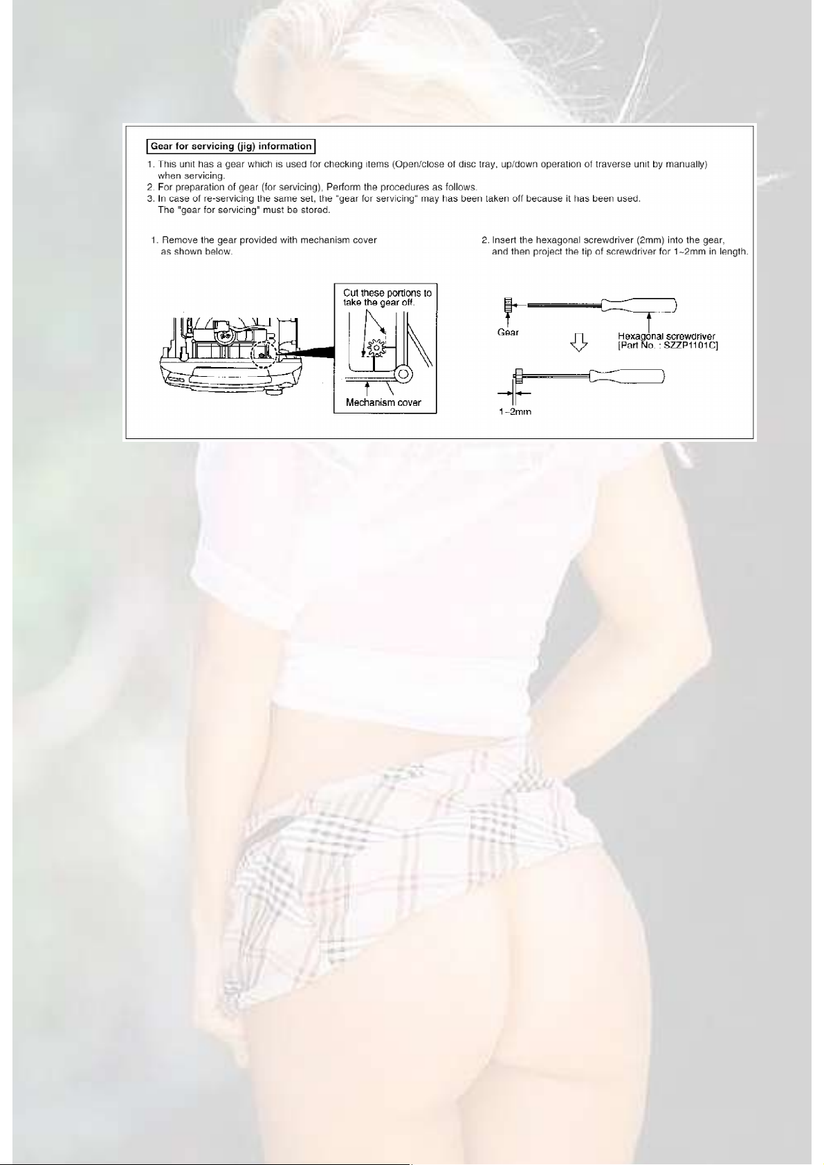
4. Handling Precaution for Traverse Deck (Optical
Pickup)
The laser diode in the traverse unit (optical pickup) may break down due to static
electricity of clothes or human body.
Use due caution to electrostatic breakdown when servicing and handling the
laser diode.
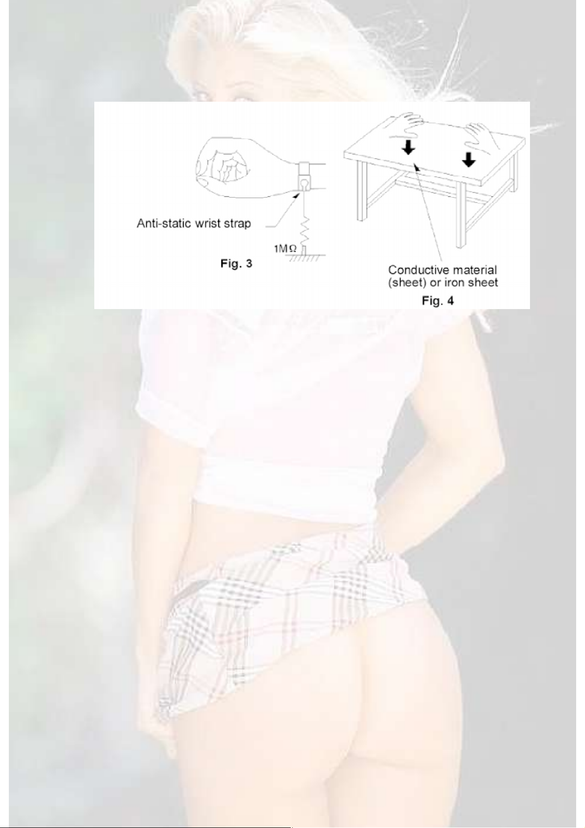
4.1. Grounding for electrostatic breakdown prevention
Some devices such as the DVD player use the optical pickup (laser diode) and
the optical pickup will be damaged by static electricity in the working
environment. Proceed servicing works under the working environment where
grounding works is completed.
4.1.1. Workable grounding
1. Put a conductive materials (sheet) or iron sheet on the area where the optical
pickup is placed, and ground the sheet.
4.1.2. Human body grounding
1. Use the anti-static wrist strap to discharge the static electricity from your body.
7
4.1.3. Handling of optical pickup
1. To keep the good quality of the optical pickup maintenance parts during
transportation and before installatio,. the both ends of the laser diode are
short-circuited. After replacing the parts with new ones, remove the short
circuit according to the correct procedure. (See this Technical Guide.)
2. Do not use a tester to check the laser diode for the optical pickup. Failure to
do so will damage the laser diode due to the power supply in the tester.
4.2. Handling Precautions for Traverse Unit (Optical Pickup)
1. Do not give a considerable shock to the traverse unit (optical pickup) as it has
an extremely high-precise structure.
2. When replacing the optical pickup, install the flexible cable and cut its short
land with a nipper. See the optical pickup replacement procedure in this
Technical Guide. Before replacing the traverse unit, remove the short pin for
preventingstatic electricity and install a new unit. Connect the connector as
short times as possible.
3. The flexible cable may be cut off if an excessive force is applied to it. Use
caution when handling the cable.
4. The half-fixed resistor for laser power adjustment cannot be adjusted. Do not
turn the resistor.
5. Precaution of Laser Diode
8

Caution :
This product utilizes a laser diode with the unit turned "ON", invisible laser
radiation is emitted from the pick up lens.
Wavelength : 780 nm
Maximum output radiation power from pick up : 100 W/VDE
Laser radiation from pick up unit is safety level, but be sure the followings:
1. Do not disassemble the optical pick up unit, since radiation from exposed
laser diode is dangerous.
2. Do not adjust the variable resistor on the pick up unit. It was already adjusted.
3. Do not look at the focus lens using optical instruments.
4. Recommend not to look at pick up lens for a long time.
ACHTUNG :
Dieses Produkt enthält eine Laserdiode. Im eingeschalteten Zustand wird
unsichtbare Laserstrahlung von der Lasereinheit abgestrahlt.
Wellenlänge : 780nm
Maximale Strahlungsleistung der Lasereinheit :100 W/VDE
Die Strahlung an der Lasereinheit ist ungefährlich, wenn folgende Punkte
beachtet werden:
1. Die Lasereinheit nicht zerlegen, da die Strahlung an der freigelegten
Laserdiode gefährlich ist.
2. Den werkseitig justierten Einstellregler der Lasereinhit nicht verstellen.
3. Nicht mit optischen Instrumenten in die Fokussierlinse blicken.
4. Nicht über längere Zeit in die Fokussierlinse blicken.
ADVARSEL :
I dette a apparat anvendes laser.
PRODUCT UTILIZES A LASER.
OF CONTROLS OR ADJUSTMENTS OR PERFORMANCE OF PROCEDURES OTHER THAN THOSE
HEREIN MAY RESULT IN HAZARDOUS RADIATION EXPOSURE.
Use of Caution Labels
9

6. Operation Procedures
101112

7. Self-Diagnostic Function
continuous
10]
PAUSE]
commands
input
7.1. Outline
- Self-Diagnosis of error conditions on user equipment according to conditions
set by the head office.
- Occurance of an error condition and results of operations that occured after
entering self-diagnostic mode are displayed via the front (FL) display panel.
7.1.1. Outline of Functions
Complex
Operation
/CD Main unit
[STOP]Main unit
[>>]
/CD Main unit
[STOP]Remote
Control [0]
Main unit
[STOP]Other
Remote Control
button
Main unit
[STOP]Main unit
[>>]
/CD Main unit
[STOP]Main unit
[>>]
Front Panel Display
(Mode-in)
Y_ _ _ _ _ _ _ _ _ _ _ _ _ [OPEN/CLOSE] Changer mechanism operation;
Button check display All buttons Button check, blink all front
T_ _ _ _ _ _ _ _ _ _ _ _ _ _ [PAUSE] Display analog device (AD)
Next Operation Test Content
-Diagnostic code acquisition
[STOP] Single
press
[STOP] Long
press
Remote
Control [5]
None Display DVD module self-
Display self-diagnostic code
Clear recorded content of error
conditions
Changer mechanism
operation test
diagnostic(Display error code)
Remote control [5] [6] [7] [9] [>=
[0].[>=10] [ENTER] [
[DISPLAY] etc.Special
for DVD module
display panel lights
value [ FF FF FF FF FF ]Front
display panel (from left) [AN0]
[AN1] [AN2] [AN3] [AN4]
Cautions:
Self-diagnostics displayed via the [STOP] key display all recorded selfdiagnostic codes.
7.2. Self-Diagnostic Mode Settings and Display
13

1. Power-source related
to
F61
there
the
item
content
self
following
to
* Example display
* Self-Diagnostic Codes
No. Error Display Error Item Detection Method
F61 Power Amp output error or power
supply circuit error
When DCDET is L during normal
operation do not POWER OFF
normally, immediately set PCNT
“GOODBYE” display and display
error.Do not start demonstrations
while error F61 is being
displayed.Record content of error
occurance and display content in
error detection mode.
2. CD/DVD Changer Mechanism (CR20)
Step Operating Procedure Micro-controller operation, processing, etc.
Switch the SELECTOR to CD/DVD, close
tray without disk
Press the [FF] button while holding down
the [STOP] button for two seconds or
Self-diagnostic mode will not be entered if
a disk in the tray.
more. Self-diagnostic mode is entered
when the [STOP] button is released.
[T ] is displayed by the front display (FL)
panel when entering self-diagnostic mode.
Press the [OPEN/CLOSE] button. Operations below wil be continued. While
operations are in progress buttons relating to
micro-controller will be ignored.
1. Change disc 1 and open the tray.
2. Close the tray 1 second after opening.
3. Initialize the mechanism.
4. Insert disc 5 in the play position and quit.
Confirm recorded error content by
pressing the [STOP] button while stopped
in the self-diagnostic mode and displaying
the results of the error check.
Each time the [STOP] button is pressed error
codes are displayed in sequence on the front
display panel Example of a DVD module
display: [_DVD_H05_ _]Example of a normal
diagnostic code display: [T_ _ _H02_ _]
Clear recorded error content by pressing
the [STOP] button for 5 seconds or more
while stopped in the self-diagnostic mode.
Recorded error content is cleared and the
is shown on the front display panel:[CLEAR] is
displayed for one second followed by a return
[T_ _ _ _ _ _ _]
14

Step Operating Procedure Micro-controller operation, processing, etc.
normal
and
Cancel self-diagnostic mode by pressing
the [POWER] button.
Power is turned off. At the next power on
operation will resume.
* If an error occurs while checking the RAM during a micro-controller reset all
recorded error detection content will be cleared while initializing the RAM.
* By skipping step 4 of the above procedure and moving directly to step 6 it is
possible to just display the self-diagnostic codes.
* Example display
* Self-Diagnostic Codes
No. Error Display Error Item Detection Method
H15 OPEN SW error If there is a failsafe for a SW error that occurs
during normal operation it will be recorded
displayed in self-diagnostic mode.
H16 CLOSE SW error SW errors will be detected even in error
detection mode.
H16 UP SW error
H17 DOWN SW error
H27 POSITION SW error
F28 DISC mount error
F29 DISC unmount error
* While stopped in conditions 3 or higher above it is possible to start a CR20
continuous test. Described in detail seperately.
3. Analog Device (AD) input value display
* Pressing the [PAUSE] button on the main unit after having entered selfdiagnostic mode through SELECTOR [DVD/CD] will show the analog device
conversion input value on the front display panel.
* Each time the button is pressed the value will be read again and the display
refreshed.
* Front display Panel:
15

AD Input Usage
AN 0 Key 1 input : Key input 1
AN 1 Key 2 input : Key input 2
AN 2 Key 3 input : Key input 3
AN 3 MK_IN1 : DECK input 1
AN 4 MK_IN2 : DECK input 2
- Exit the Analog Device input value display mode by cutting off the AC
power source and next time could start the device.
4. DVD/CD module
Step Operating Procedure Micro-controller operation, processing, etc.
Set the SELECTOR to CD/DVD
While pressing the [STOP] button on the
main unit press [0] button on the remote
control
See the “DVD/CD/ Changer Control” section of
“Error Display” for a detailed explanation.
* Since error detection for the DVD/CD module occurs in the system
component and is sent through the mechanism component codes are
received and displayed at the operating console.
* Since self-diagnostic codes for the DVD/CD module duplicate prior audio
codes the self-diagnostic codes are displayed prefixed by “DVD”.
* Self-Diagnostic Codes
16

No. Error Display Error Explanation Cause (IC number, etc.)
F010 Specified value is larger than the
Disk IC7001
specified parental value.
F020 No TT_SRPT (RLBN is 0)
F021 TT_SRP number is 0
F022 Specified value is larger than the
Disk IC7001
Disk IC7001
Disk IC7001
TT_SRP number
F023 No matching SRP for VTSN or
Disk IC7001
VTS_TTN
F024 Specified value is larger than
Disk IC7001
TT_SRP.PTT_Ns
F030 TTU_SRP number is 0
F031 Specified value is larger than
Disk IC7001
Disk IC7001
TTU_SRP number
F040 SRP1 number is 0
F041 PGCI_SRP number is 0
F042 Specified value is larger than the
Disk IC7001
Disk IC7001
Disk IC7001
PGCI_SRP number
F043 No matching PGCI_SRP for this Menu
Disk IC7001
ID
F050 TMAP_SRP number is 0
F051 Specified value is larger than the
Disk IC7001
Disk IC7001
TMAP_SRP number
F052 Specified TMAP_SA is 0
F053 MAP_EN number is 0
F060 C_POSIT exists, but there is no
Disk IC7001
Disk IC7001
Disk IC7001
PGMAP in the PGC
F061 C_POSIT exists, but the PG number in
Disk IC7001
the PGC is 0
F062 Specified value is larger than the PG
Disk IC7001
number in the PGC
F063 C_POSIT exists, but there is no
Disk IC7001
C_PBIT in the PGC
F064 C_POSIT exists, but the PG number in
Disk IC7001
the PGC is 0
F065 Specified Cell number is 0
F066 Specified value is larger than the Cell
Disk IC7001
Disk IC7001
number in the PGC
F067 Must be a block array
F070 Is not NV_PCK data
FOB0 No Cell number for current search
Disk IC7001
Disk IC7001
Disk IC7001
F0E0 No user guide PGC control file for
DFD, cannot resolve
17

No. Error Display Error Explanation Cause (IC number, etc.)
IC6201
F0E1 DFD main micro-controller type not
compatible, cannot download
F0E2 DFD download start; PGC playback
error
F0E3 Waiting for DFD download completion;
PGC playback error
F0E4 AVDEC during DFD download
F0E5 Firmware file read error during DFD
download
F0E6 Interpolation check error in read-in
DFD firmware
F0F0 No firmware file for DFD; download
unnecessary
F0F1 No firmware matching the DFD
download parameters; download
unnecessary
F103 Illegal Highlight Position
F4FF No ACK when requesting forced
Disk IC7001
Panel Component IC6001
initialization of panel component
F500 DSC Error IC2001
F501 DSC Not Ready Error IC2001
F502 DSC Time Out Error IC2001
F503 DSC Communication Failure IC2001
F504 Error adjusting DSC data slice offset IC2001
F505 DSC Attention Error IC2001
F506 Can’t determine media type (invalid
IC2001
media type)
F600 Can’t access administrative data due
IC7001
to demodulation error
F601 Undefined sector ID requested IC7001
F602 Can’t access LEAD_IN data due to
IC7001
demodulation error
F603 Can’t access KEY_DET due to
IC7001
demodulation error
F610 Can’t control ODC IC7001
F611 No CRCOK within the set time period
IC7001
(CD related)
F612 No CRCOK within the set time period
IC7001
(DVD related)
F620 Laser safeguard: high temperature
condition
F621 Laser safeguard: circuit failure
condition
F700 MBX Overflow
System component bug
18

No. Error Display Error Explanation Cause (IC number, etc.)
IC6201
IC6201
IC6201
IC6201
IC6201
IC6201
number,etc.)
F701 Message Command Not Complete
Error
F702 Message Command Changed
F880 Task number not relevant
F890 Attempted to send message while
sending to an AV task (mailbox
overflow, etc.)
F891 Couldn’t send message to AV task
(mailbox overflow, etc.)
F8A0 Message command is not relevant
F893 Flash ROM is interpolated IC6302
F894 EEPROM is not normal IC6303
No. Error Display Error Explanation Cause (IC
U11 Focus servo error
H01 Tray loading error
H02
H03 Traverse motor error
H04 Tracking server error
H05 SEEK timeout error
Spindle server error
DSC disc motor error
6626 CLVS FAILURE
System component bug
System component bug
System component bug
System component bug
System component bug
System component bug
7.3. Additional Functions
7.3.1. Tray Lock Function
- There are two tray lock functions
- Power on through the SELECTOR /DVD/CD. While holding down the [CD STOP]
button on the main unit press the [POWER] button on the main unit or the
remote control. Lock Mode A will be entered, [_ _ _ _LOCKED_ _] will be
displayed for 3 seconds, and the current disc will begin playing.
- Lock Mode A will disable the button below while turning the power on or off.
[OPEN/CLOSE]
- When locked in Lock Mode A pressing the [POWER] button on the main unit or
the remote control while holding down the [CD STOP] button on the main unit
will display [_ _UNLOCKED_ _] and unlock the unit.
19

- Power on through the SELECTOR DVD/CD. While holding down the [CD PLAY]
button on the main unit press the [POWER] button on the main unit or the
remote control. Lock Mode B will be entered, [_ _ _LOCKED_ _] will be
displayed for 3 seconds, and the current disc will begin playing.
- In Lock Mode B the button below, mainly selector and disc operation related
items, will be disabled.
Main Unit: [DISC 1] ~ [DISC 5] [OPEN/CLOSE] [DISPLAY/DEMO] [CLOCK/
TIMER] [T.PLAY/REC] [SELECTOR] [STOP] [TUNER/BAND] [TAPE < >] [I<</<<]
[>>/>>I] [PAUSE] [TAPE EJECT] [REV MODE] [REC/STOP]
Remote Control: [SLEEP] [AUTO OFF] [DIMMER] [MIX 2ch] [MUTING] [0] ~ [9] [>
=10] [DISC]
[RETURN] [DISPLAY] [TEST] [CH SELECT] [TUNER/BAND] [TAPE < >]
[SELECTOR] [REPEAT]
[MARKER] [STOP] [PAUSE] [I<<] [>>I] [<<] [>>]
[KARAOKE ON/OFF] [KARAOKE DISP] [KARAOKE MODE] [ONE TOUCH]
[ECHO]
[KEYCON b] [KEYCON #] [MIC -] [MIC +] [SETUP]
While playing it is not necessary to re-disable buttons disabled under Lock
Mode B.
Also, button related to sound quality are not disabled. The buttons below are
not disabled.
Main Unit: [POWER] [CD MANAGER] [AMAZING] [DVD/CD] [CINEMA] [DPL]
[SSS]
Remote Control: [POWER] [SET UP] [PLAY MODE] [CLEAR] [EQ] [3D AI]
[SUPER W] [VOL -] [VOL +]
[DVD/CD >] [MENU] [TOP MENU] [<] [>] [^] [v] [ENTER]
[SUB TITLE] [AUDIO] [ANGLE]
- When locked in Lock Mode B pressing the [POWER] button on the main unit or
the remote control while holding down the [CD PLAY] button on the main unit
will unlock the unit after displaying [_ _UNLOCKED_ _] for 3 seconds.
- Tray lock is canceled when AC power is cut.
- Tray lock A and B functions are exclusive operations. The first one enabled will
have priority.
- When a disabled button is pressed while in lock mode [_ _ _LOCKED_ _] will
be displayed for 3 seconds on the front display panel.
- Lock mode will be cancelled when a loading error occurs with the CR20.
(If the [OPEN/CLOSE] button were disabled when the tray is opened by a TAKE
OUT DISC error recovery would be impossible)
20

7.3.2. Special Commands for the DVD Module
from
the
and
the
and
- When the SELECTOR is set to DVD/CD the commands for the operations
below will be sent to the mechanism component micro-controller.
- The mechanism component micro-controller relays these commands without
alteration to the DVD module.
- THe DVD module sends data resulting from commands to the mechanism
component, where they are then relayed to the operating console.
- Data received from the DVD module by the operating console is displayed by
the right 10 digits.
- Command Table
Special
Operation
Display
test
Command Operation/Display Release/Remarks
B5
B6
B7
Main Unit [STOP] + Remote Control [5]
xxx: jitter measurement (DEC)
[xxx_yyy_zz] yyy:read error counter (DEC)
zz: focus drive measurement (HEX)
Test string from DVD MODULE :[J_xxx_yyy_zz]
Main Unit [STOP] + Remote Control [6]
w: region number
[_ _w_xy_zzz] x: N noPAL P PAL
y: N NTSC 6 PAL60
zzz: panel component jumper data
Text string from DVD MODULE: [_ _w_xy_zzz]
Main Unit [STOP] = Remote Control [7]
s: panel component mode type
[srrrxxyzzz] rrr: panel component release
number
[_ _ _xxyzzz] x: generation of system
component (45)
y: system component model type
zzz: system component release number
Text string from DVD MODULE: [srrr_ _xxyzzz]
srrr will be blank with mini-components
Send STOP command
operating console
5 seconds after activation
text string from the DVD
MODULE dissappears
display is automatically
turned off.
5 seconds after activation
text string from the DVD
MODULE dissappears
display is automatically
turned off.
21

Special
the
and
tray
from
the
from
the
from
the
on
the
Operation
Code BA +
Current
laser
value)
Laser C3
RAM
A
RAM
B
pick
users)
Command Operation/Display Release/Remarks
request
record
number
Main Unit [STOP] + Remote Control [0]
[__DVD_Fxxx] xxx: error number
[__DVD_Uxxx]
[__DVD_Hxxx]
5 seconds after activation
text string from the DVD
MODULE dissappears
display is automatically
turned off.
C2
Main Unit [STOP] + Remote Control [PAUSE]
[DO_034_028] 034: DVD current measurement
(mA) (DEC)
028: CD current measurement (mA) (DEC)
Text string from DVD MODULE: [LDO_034_028]
C4
Main Unit [STOP] + Remote Control [DISPLAY]
034: saved in EEPROM
[DD_034_032] initial current mearement (mA)
(DEC)
032: present current measurement (mA) (DEC)
Text string from DVD MODULE: [LDD_034_032]
Main Unit [STOP] + Remote Control [1]
[A_0FA_6901] 0FA: address (HEX)
6901: RAM value of display address (HEX)
Laser lighting remains on
until POWER OFF of the
opens.
STOP command is sent
the operating console to
DVD MODULE
C5
Main Unit [STOP] + Remote Control [2]
[A_0FA_6901] 0FA: address (HEX)
6901: RAM value of display address (HEX)
STOP command is sent
the operating console to
DVD MODULE
C6
Main Unit [STOP] + Remote Control [9]
[FK_109_101] 109: maximum value of
calculated value (DEC)
101 : ratio of maximum value to minimum value
[FK_ER_9101] ER: display error occurance
STOP command is sent
the operating console to
DVD MODULE
9101: ADSC command error code
BC+
Model Table
+ 0 x 00
Main Unit [STOP] + Remote Control [>=10]
[INITIALIZED] display on the operating
console for 2 seconds.
When display clears the user initialization
commands is output the system component.
When the [INITIALIZED]
front panel dissappears
operation is complete.
GUI is INITIALIZE.
Returns user settings to factory values.
22

Special
be
RESET
display
temporarily
be
is
display
the
after
the
Operation
Reset
design
set
industrial
Name B1+
Time B1+
Command Operation/Display Release/Remarks
BC+
Model Table
+ 0 x 3C
While [INITIALIZED] is being displayed from
the user initialization operation press [STOP]
on the main unit and [ENTER] on the remote
control.
[_DVD_RESET] is displayed on the operating
console and the all reset command is output
instead of the user initialization command.
Returns user settings to factory values.
Panel component jumpers are referenced, and
If NO DISC or ---READ can
confirmed after DVD
displayed on the front
panel the operation is
completed.
No GUI. All items
dissappear.
the appropriate model number’s initialization
values are written to the EEPROM and global
region.
Laser times and spindle times are not
initialized.
F1
Receipt of remote control code [B0 00 F1].
Also, Main Unit [STOP] + Remote Control
[1DDF]
[_ALL_SET] (display text string from system
component).
Returns user settings to factory values.
Panel component jumpers are referenced, and
the appropriate model number’s initialization
values are written to the EEPROM and the
global region.
Laser times and spinlde times are also
If NO DISC or ---READ can
confirmed after ALL SET
displayed on the front
panel the operation is
completed.
ALL SET is displayed on
front displaye panel the
operation is completed.
GUI is ALL SET.
initialized.
0 x 13
Main Unit [STOP] + Remote Control [4]
[FEP_??????] [SRV_??????] [ODC_??????]
[Av_??????] [SYS_??????]
Display cycles every 3
seconds. Display
automatically turns off
the last device name is
displayed.
0 x 14
Main Unit [STOP] + Remote Control [^]
1234 : DVD laser use time
[_1234_5678] 5678: CD laser use time
10 hour units displayed in 4 digits
Text string from DVD MODULE: [T1_1234_5678]
5 seconds after activation
text string from the DVD
MODULE dissappear and
display is automatically
turned off.
23

Special
the
the
the
until
opens.
the
Operation
Laser
Use
Use B1 +
Spindle
Time
Laser
and BF +
Command Operation/Display Release/Remarks
B2 +
0 x 14
0 x 15
B2 +
0 x 15
B1 +
0 x 92
0 x 92
While use time is being displayed press
Main Unit [STOP] + Remote Control [V]
[_0000_0000]
DVD and CD are both reset at the same time.
Main Unit [STOP] + Remote Control [>]
[___T2_1234] 1234: 10 hour units displayed in
4 digits
Text string from DVD MODULE: [T2_1234_____]
While use time is being displayed press
Main Unit [STOP] + Remote Control [<]
[___T2_0000]
Main Unit [STOP] + Remote Control [3]
028: initial current value
[DC_028_026] stored in EEPROM (mA)
026: Present current value (mA)
Text string from DVD MODULE: [LDG_028_026]
Main Unit [STOP] + Remote Control [8]
r: region number
[__r__xyzzz] x: generation of system
component
y: system component model type
zzz: system component model type
Text string from DVD MODULE: [____r__xyzzz]
5 seconds after activation
text string from the DVD
MODULE dissappear and
display is automatically
turned off.
5 seconds after activation
text string from the DVD
MODULE dissappear and
display is automatically
turned off.
5 seconds after activation
text string from the DVD
MODULE dissappear and
display is automatically
turned off.
Laser lighting continues
POWER OFF or the tray
5 seconds after activation
text string from the DVD
MODULE dissappear and
display is automatically
turned off.
7.3.3. Jitter Offset Correction
- The jitter offset correction function below is necessary for D5, but is not
necessary for D8.
- While displaying K objects,certain remote control operations correct the offset
of the DVD MODULE jitter value.
- When the DVD module firmware rewriting connector is inserted K objects will
24

be displayed [KC 00 0000].
- Key codes of input from the remote control’s ten key while displaying K
objects are relayed to the system component by the operating console.
- Inputting [2] [0] from the remote control returns a 14 hex value from the
system component. The value is converted from hex dec and displayed as
[KC 20 0000].
- Continuously pressing the [PLAY] button returns the offset result as a text
string from the system component, which is displayed as [KC 20 0002].
- The DVD Module has functions that support buttons other than [2] [0] [PLAY],
so when K objects are being displayed key codes are as below.
[0] [1] [2] [3] [4] [5] [6] [7] [8] [9] [>=10] [PLAY]
7.4. Pseudo ROM Correction
7.4.1. Outline
- Since the Mitsubishi M3819 series micro-controller is capable of making
programs operate in RAM the pseudo ROM corrections below are possible.
- Program the process calling the modifying sub-routine in advance.
- Program the process to read-out the program from the EEPROM into RAM in
advance.
- Processes previous to the read-out cannot be modified.
- In pseudo ROM corrections defective processses cannot be completely
bypassed.
7.4.2. EERPOM Flag Indicator Interpretation
- Regardless of the EEPROM flag indicator CS/CLK/DATA is output and the
DATA read-in process occurs.
Accordingly, even if there is no EEPROM hardware processing at the terminal
is necessary.
- If the data read-out below is valid then an EEPROM will be determined to be
present, and the modifying program will be read-out.
- When the MASK ROM file name (8 character ASCII code, 8 bytes) and the
EEPROM file name match.
25
- When the modifying points flag indicator data (8 points, 1 byte) written at two
places on the EEPROM match.
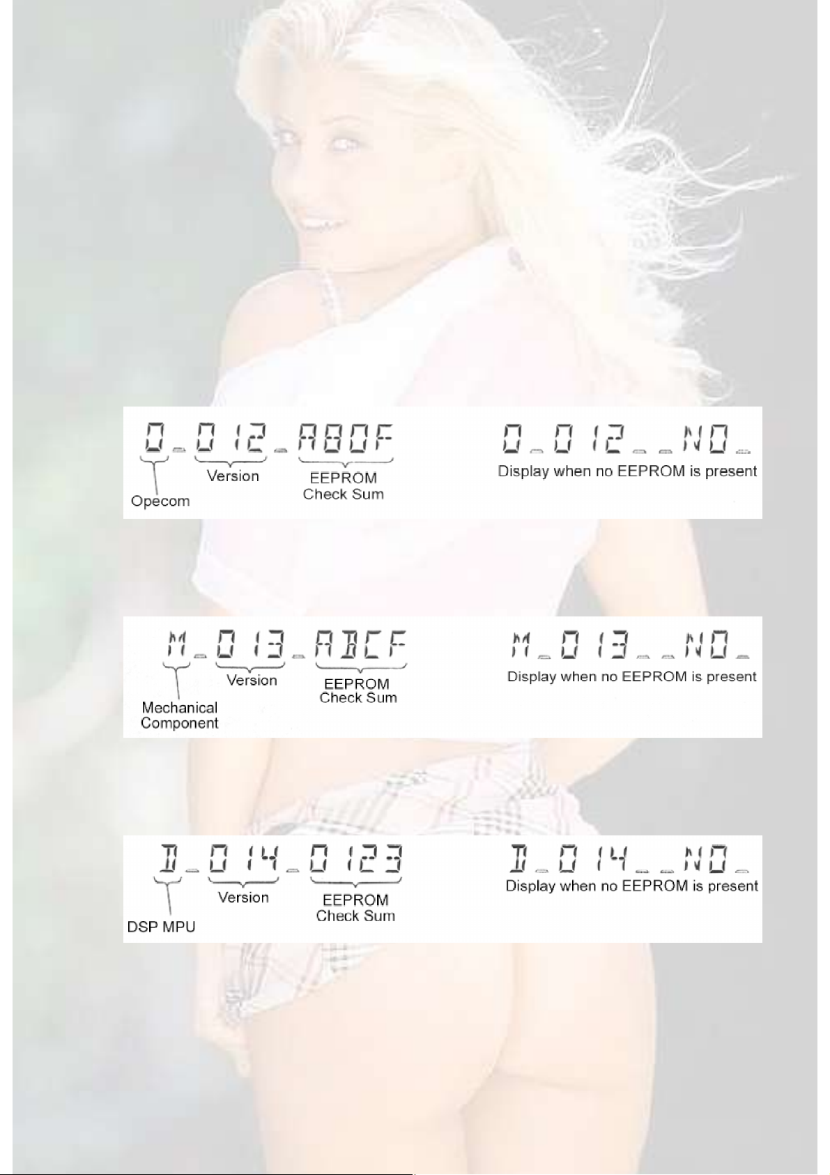
7.4.3. CHECK SUM Display
- In order to confirm that the EEPROM is loaded, the operations below display
the CHECK SUMs for the Operating Console, mechanism component, and DSP
micro-controller EEPROMs.
- Receiving [1DDF or 1CDF] when in Process Check Mode with Process Check
Mode-in [1DDF or 1 CDF] will display the operating console’s version and
EEPROM CHECK SUM.
- If [1DDF or 1CDF] are received while the operating console’s version and
EEPROM CHECK SUM are being displayed the mechanism component’s
version and EEPROM CHECK SUM are displayed.
- If [1DDF or 1CDF] are received while the mechanism component’s version and
EEPROM CHECK SUM are being displayed the DSP micro-controller’s version
and EEPROM CHECK SUM are displayed.
- If a valid remote control code is received while the CHECK SUM is being
displayed the CHECK SUM display will be erased to confirm with that
operation and display.
26

- When the result of referencing the EEPROM is a differing file name [NO] will be
displayed, just as when no EEPROM is present.
7.4.4. Insertion Points for ROM Correction Processing
- Processing read-outs from EEPROM
- RCaccE2PrSUB: Insert after port or control register setting (AC check).
It is also necessary for the EEPROM’s power supply to be in power-off (AC
positive).
- Processing Modifying Program Calls
- RCtimerinsSUB: Insert at the end of the timer interrupt.
- RCschedulerSUB: Insert in the OS scheduler.
- RCinitialSUB: Insert after initialization, immediately before jumping to the main
process.
- RCstandbySUB: Insert immediately before the power failure process STP
command.
- RCimagetskSUB: Insert immediately before branching to individual image
processing.
- RCdisptskSUB: Insert immediately before processing the data settings for the
display RAM.
- Rcreserve0SUB: Insert in the transmission process to the CD mechanism
component.
- Rcreserve1SUB: Insert in the transmission process to the DSP control micro-
controller.
- Data inside the EPROM (Required RAM capacity)
- EEPROM flag indicator determination data: 10 bytes
- Modifying Program’s starting address: 16 bytes
- Modifying Program: remaining bytes
8. Disassembly and Main Component Replacement
Procedures
27
“ATTENTION SERVICER”
Some chassis components may have sharp edges.
Be careful when disassembling and servicing.
1. This section describes procedures for checking the operation of the major
printed circuit boards and replacing the main components.
2. For reassembly after operation checks or replacement, reverse the respective
procedures.
Special reassembly procedures are described only when required.
3. Select items from the following index when checks or replacement are
required.
Warning:
This product uses a laser diode. Refer to caution statement Precaution of Laser
Diode.
8.1. Checking for the Main and DVD F/E Module (1/2) and (2/
2) P.C.B.
28
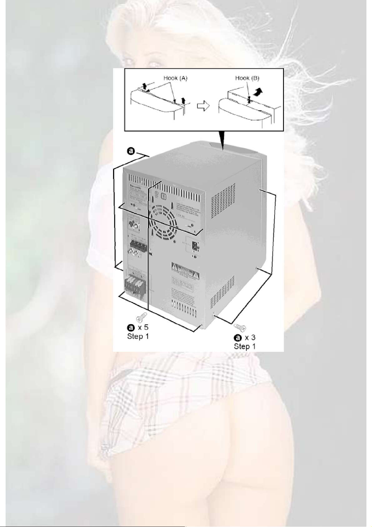
Step 1 Remove 3 screws each both side and 5 screws at rear panel.
Step 2 Lift up the both sides cabinet ass’y to release the hook (A). Then pull the
cabinet ass’y toward the rear and release the hook (B) to remove the cabinet
ass’y.
NOTE: When installing the cabinet ass’y, take care not to damage the front
cabinet ass’y from hook (B).
- Check the Main P.C.B. and DVD F/E Module (1/2) P.C.B..
29
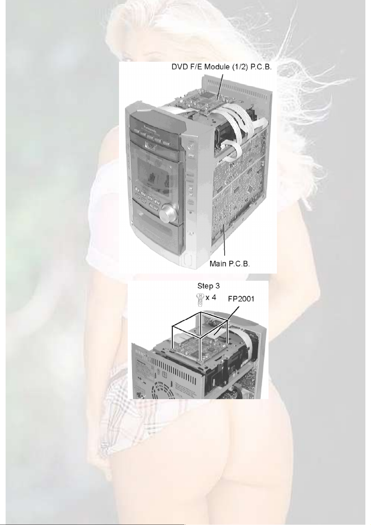
Step 3 Remove 4 screws.
Step 4 Remove 4 connectors.
Step 5 Pull out 4 FFCs.
30
 Loading...