

A
A
AV Control Receiver
SA-BX500PP
Colour
(K).......................Black Type
ORDER NO. MD0808003CE
A1
Specifications
Main unit SA-BX500PP
O
OGENERAL
OO
Power supply: AC 120V, 60 Hz
Power consumption: 150 W
Power consumption in standby mode:
approx. 0.7 W
Power consumption in HDMI off mode:
approx. 0.4 W
Dimensions (W×H×D): 430 mm × 158.5 mm × 339
mm
(16-15/16” x 6-1/4” x 13-11/32”)
Mass: Approx. 5 kg (11 lb.)
Operating temperature range: 0°Cto40°C
Operating humidity range: 20% to 80% RH
(no condensation)
O
OAMPLIFIER SECTION
OO
Rated minimum sine wave RMS power output
20 Hz-20 kHz both channels
driven (with AES17 filter)
0.7 % total harmonic distortion
130 W per channel (6 Ω)
Total harmonic distortion
Rated power at 20 Hz-20 kHz
0.7% (6 Ω)
Power output each channel driven at 20 Hz-20 kHz
(with AES17 filter)
Front (L/R):
130 W per channel (6 Ω)
Center:
130 W per channel (6 Ω)
Surround (L/R):
130 W per channel (6 Ω)
Surround Back (L/R):
130 W per channel (6 Ω)
Total Harmonic distortion:
0.7% W
Load impedance
Front (L/R)
or B:
4to8Ω
and B:
6to8Ω
BI-WIRE:
© 2008 Matsushita Electric Industrial Co. Ltd.. All
rights reserved. Unauthorized copying and
distribution is a violation of law.
A
SA-BX500PP
Center:
Surround (L/R):
Surround Back (L/R):
Frequency Response
CD, AUX, TV, GAME, CABLE/SAT, VCR, DVD RECORDER,
BD/DVD PLAYER/ ANALOG 8CH IN, OPTION PORT
4Hzto40kHz,±2dB
Input sensitivity and impedance
CD, AUX, TV, GAME, CABLE/SAT, VCR, DVD RECORDER,
BD/DVD PLAYER/ ANALOG 8CH IN, OPTION PORT
16 mV (200 mV, IHF’66) 22 kΩ
S/N (IHF A)
CD, TV, BD/DVD PLAYER, DVD RECORDER (Digital Input)
97 dB, IHF’66
Tone controls
BASS: 50 Hz, +10 to -10 dB
TREBLE: 20 kHz, +10 to -10 dB
Output Voltage
DVD RECORDER: 200 mV
This unit supports “HDAVI Control 3” function.
Digital input (OPTICAL):
Digital input (COAXIAL):
HDMI Input (Corresponding Deep Colour)
HDMI Output (Corresponding Deep Colour)
O
OFM TUNER
OO
Frequency Range
87.9 to 107.9 MHz (200-kHz steps)
87.5 to 108.0 MHz (100-kHz steps)
Sensitivity
11.2 dBf (2 µV, IHF’58)
Total harmonic distortion
MONO 0.5%
STEREO 0.7%
S/N
MONO 73 dB
STEREO 67 dB
Alternate channel selectivity
Antenna terminal
75 Ω (unbalanced)
Frequency response
20 Hz to 15 kHz, +1 dB, -2 dB
O
OAM TUNER SECTION
OO
Frequency range:
520 to 1710 kHz
O
OOption Port SECTION
OO
4to8Ω
6to8Ω
6to8Ω
6to8Ω
65 dB
n exclusive terminal for SH-PD10 (option)
O
OVIDEO SECTION
OO
Output voltage at 1 V input (unbalanced)
Maximum input voltage
Input/output impedance
Composite Video (Input)
Composite Video (Output)
S-Video (Input)
S-Video (Output)
Component Video (Input)
Component Video (Output)
3
Note:
1
1. Specifications are subject to change without notice.
3
2. Total harmonic distortion is measured by the digital spectrum
analyzer.
Solder:
1
This model uses lead free solder (PbF).
1
1±0.1Vp-p
1.5 Vp-p
75 Ω
BD/DVD PLAYER, DVD
RECORDER, VCR,
CABLE/SAT, GAME, AUX
DVD RECORDER, TV
MONITOR
BD/DVD PLAYER, DVD
RECORDER, VCR,
CABLE/SAT, GAME, AUX
DVD RECORDER, TV
MONITOR
BD/DVD PLAYER, DVD
RECORDER, CABLE/SAT
TV MONITOR
2
SA-BX500PP
CONTENTS
Page Page
1 Safety Precautions 5
1.1. GENERAL GUIDELINES
1.2. Before Repair and Adjustment
1.3. Protection Circuitry
1.4. Safety Parts Information
2 Prevention of Electrostatic Discharge (ESD) to
Electrostatically Sensitive (ES) Devices
3 About Lead Free Solder (PbF)
3.1. Service caution based on legal restrictions
4 Accessories
5 Operation Procedures
5.1. Remote Control Key Buttons Operations
5.2. Main Unit Key Buttons Operations
5.3. Using the VIERA Link “HDAVI Control™”
5.4. Main Unit Connections
6 Self-Diagnosis and Display Function
6.1. Automatically Displayed Error Codes
6.2. Display Details
6.3. Overload/Shutdown Detection internal Condition
6.4. Overload/Thermal Detection Display
6.5. Activating Self Diagnosis Function (Service Mode)
6.6. Returning to Normal Display
6.7. Activating Self Diagnosis Function (Doctor Mode)
6.8. Wireless Link
7 Assembling and Disassembling
7.1. Disassembly Flow Chart
7.2. Main Components and P.C.B. Locations
7.3. Disassembly of Top Cabinet
7.4. Disassembly and checking of DSP (Side A/B) P.C.B.
7.5. Disassembly and checking of Speaker P.C.B.
7.6. Disassembly and checking of D-Amp B (3CH) & Fan
P.C.B.
7.7. Replacement of Digital Amp IC (IC5000) of D-Amp B
(3CH) P.C.B.
7.8. Disassembly and checking of SMPS & AC Inlet P.C.B.
7.9. Replacement of Switch Regulator IC (IC5701)
7.10. Replacement of Switch Regulator Diode (D5702)
7.11. Replacement of Regulator Diode (D5801)
7.12. Replacement of Regulator Diode (D5802)
7.13. Replacement of Regulator Diode (D5803)
10
10
11
12
13
21
21
21
22
22
22
23
23
24
26
27
28
29
29
30
30
32
33
34
35
37
37
38
5
5
5
6
7
8
8
9
7.14. Disassembly and checking of D-Amp A (4CH) P.C.B.
7.15. Replacement of Digital Amp IC (IC5000) of D-Amp A
(4CH) P.C.B.
7.16. Disassembly and checking of HDMI side (A) and side (B)
7.17. Disassembly and Checking of S-Video & Video P.C.B.
7.18. Disassembly and checking of Wireless Adapter, Digital &
D-Port P.C.B.
7.19. Disassembly and Checking of Main (Side A/B) P.C.B.
7.20. Disassembly of Front Panel
7.21. Disassembly and checking of Panel, Headphone, Volume
P.C.B.
8 Voltage and Waveform Chart
8.1. HDMI P.C.B.
8.2. DSP P.C.B.
8.3. D-Amp A (4CH) P.C.B.
8.4. D-Amp B (3CH) P.C.B.
8.5. Main P.C.B.
8.6. Panel P.C.B.
8.7. Digital, Speaker & Fan P.C.B.
8.8. Video P.C.B.
8.9. S-Video P.C.B.
8.10. SMPS P.C.B.
8.11. Waveform Chart
9 Illustration of IC’s, Transistors and Diodes
10 Wiring Connection Diagram
11 Block Diagra m
11.1. System Control
11.2. HDMI
11.3. IC Terminal (HDMI) Chart
11.4. DSP
11.5. IC Terminal (DSP) Chart
11.6. Audio
11.7. Digital Audio Amp (4CH)
11.8. Digital Audio Amp (3CH)
11.9. Speaker Channel
11.10. Video (component & composite video)
11.11. Video (S-video)
11.12. Power
12 Schem atic Diagram Notes
39
40
41
42
42
44
45
46
48
48
50
53
54
55
58
58
59
59
59
60
62
63
65
65
66
67
68
70
72
74
75
76
77
78
79
81
3

SA-BX500PP
13 Schematic Diagram 83
13.1. HDMI Circuit
13.2. DSP Circuit
13.3. Main Circuit
13.4. Panel Circuit
13.5. S-Video Circuit
13.6. Speaker Circuit
13.7. Video Circuit
83
87
93
101
103
104
105
13.8. D-Port, Headphone, Digital, Volume, Wireless Adapter,
Fan Circuit
13.9. D-Amp A (4CH) Circuit
13.10. D-Amp B (3CH) Circuit
13.11. SMPS Circuit
13.12. AC Inlet Circuit
14 Prin ted Circui t Board
14.1. HDMI P.C.B.
14.2. DSP P.C.B.
14.3. Main P.C.B.
106
107
109
111
113
115
115
116
117
14.4. D-Port, Panel, S-Video P.C.B.
14.5. Headphone, Speaker, Digital, Video, Volume P.C.B.
14.6. Wireless Adapter, Fan, AC Inlet P.C.B.
14.7. D-Amp A (4CH) P.C.B.
14.8. D-Amp B (3CH) P.C.B.
14.9. SMPS P.C.B.
15 Basic Troubleshoo ting Guide
15.1. Troubleshooting Guide for F61 and/or F76
16 Overall Simplified Block for BX500
17 Terminal Function of IC’s
17.1. IC8001 (RFXWBX500EBK): Micro-processor
17.2. IC501 (C0HBB0000057): IC FL Driver
18 Expl od ed View s
18.1. Cabinet Parts Location
18.2. Packaging
19 Repl acement Parts List
19.1. Component Parts List
20 Schem atic Diagra m for printing with letter size
118
119
120
121
122
123
125
125
133
135
135
135
137
137
140
141
141
164
4
SA-BX500PP
1 Safety Precautions
1.1. GENERAL GUIDELINES
1. When servicing, observe the original lead dress. If a short circuit is found, replace all parts which have been overheated or
damaged by the short circuit.
2. After servicing, see to it that all the protective devices such as insulation barriers, insulation papers shields are properly
installed.
3. After servicing, carry out the following leakage current checks to prevent the customer from being exposed to shock hazards.
1.1.1. LEAKAGE CURRENT COLD CHECK
1. Unplug the AC cord and connect a jumper between the two prongs on the plug.
2. Measure the resistance value, with an ohmmeter, between the jumpered AC plug and each exposed metallic cabinet part on
the equipment such as screwheads, connectors, control shafts, etc. When the exposed metallic part has a return path to the
chassis, the reading should be between 1MΩ and 5.2MΩ.
When the exposed metal does not have a return path to the chassis, the reading must be
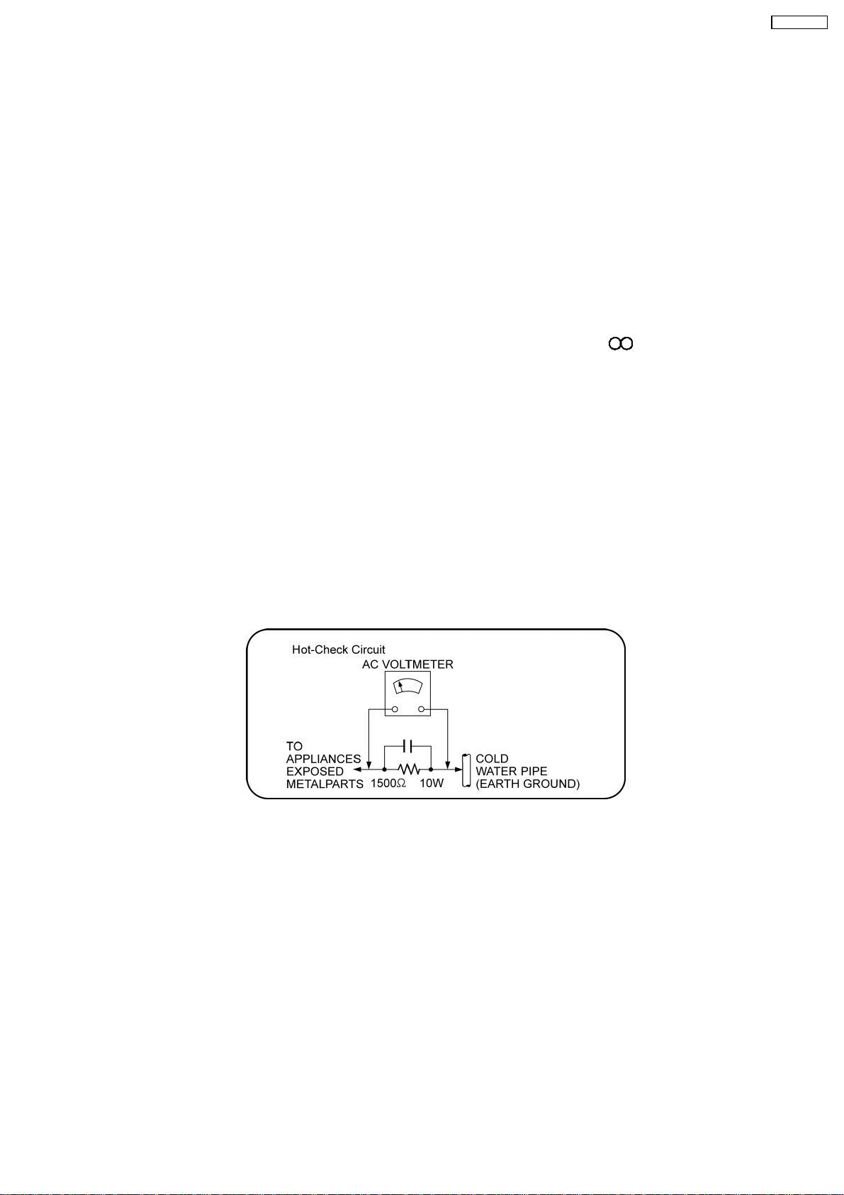
1.1.2. LEAKAGE CURRENT HOT CHECK
1. Plug the AC cord directly into the AC outlet. Do not use an isolation transformer for this check.
2. Connect a 1.5kΩ, 10 watts resistor, in parallel with a 0.15µF capacitors, between each exposed metallic part on the set and a
good earth ground such as a water pipe, as shown in Figure 1.
3. Use an AC voltmeter, with 1000 ohms/volt or more sensitivity, to measure the potential across the resistor.
4. Check each exposed metallic part, and measure the voltage at each point.
5. Reverse the AC plug in the AC outlet and repeat each of the above measurements.
6. The potential at any point should not exceed 0.75 volts RMS. A leakage current tester (Simpson Model 229 or equivalent) may
be used to make the hot checks, leakage current must not exceed 1/2 milliamp. In case a measurement is outside of the limits
specified, there is a possibility of a shock hazard, and the equipment should be repaired and rechecked before it is returned to
the customer.
Figure 1
1.2. Before Repair and Adjustment
Disconnect AC power to discharge unit AC Capacitors as such (C5700, C5701, C5702, C5703, C5704) through a 10 Ω,10W
resistor to ground.
Caution:
DO NOT SHORT-CIRCUIT DIRECTLY (with a screwdriver blade, for instance), as this may destroy solid state devices.
After repairs are completed, restore power gradually using a variac, to avoid overcurrent.
Current consumption at AC 120 V, 60 Hz in NO SIGNAL mode volume minimal should be ~ 600 mA.
1.3. Protection Circuitry
The protection circuitry may have operated if either of the following conditions are noticed:
•
• No sound is heard when the power is turned on.
• •
•
• Sound stops during a performance.
• •
The function of this circuitry is to prevent circuitry damage if, for example, the positive and negative speaker connection wires are
5
SA-BX500PP
“shorted”, or if speaker systems with an impedance less than the indicated rated impedance of the amplifier are used.
If this occurs, follow the procedure outlines below:
1. Turn off the power.
2. Determine the cause of the problem and correct it.
3. Turn on the power once again after one minute.
Note:
When the protection circuitry functions, the unit will not operate unless the power is first turned off and then on again.
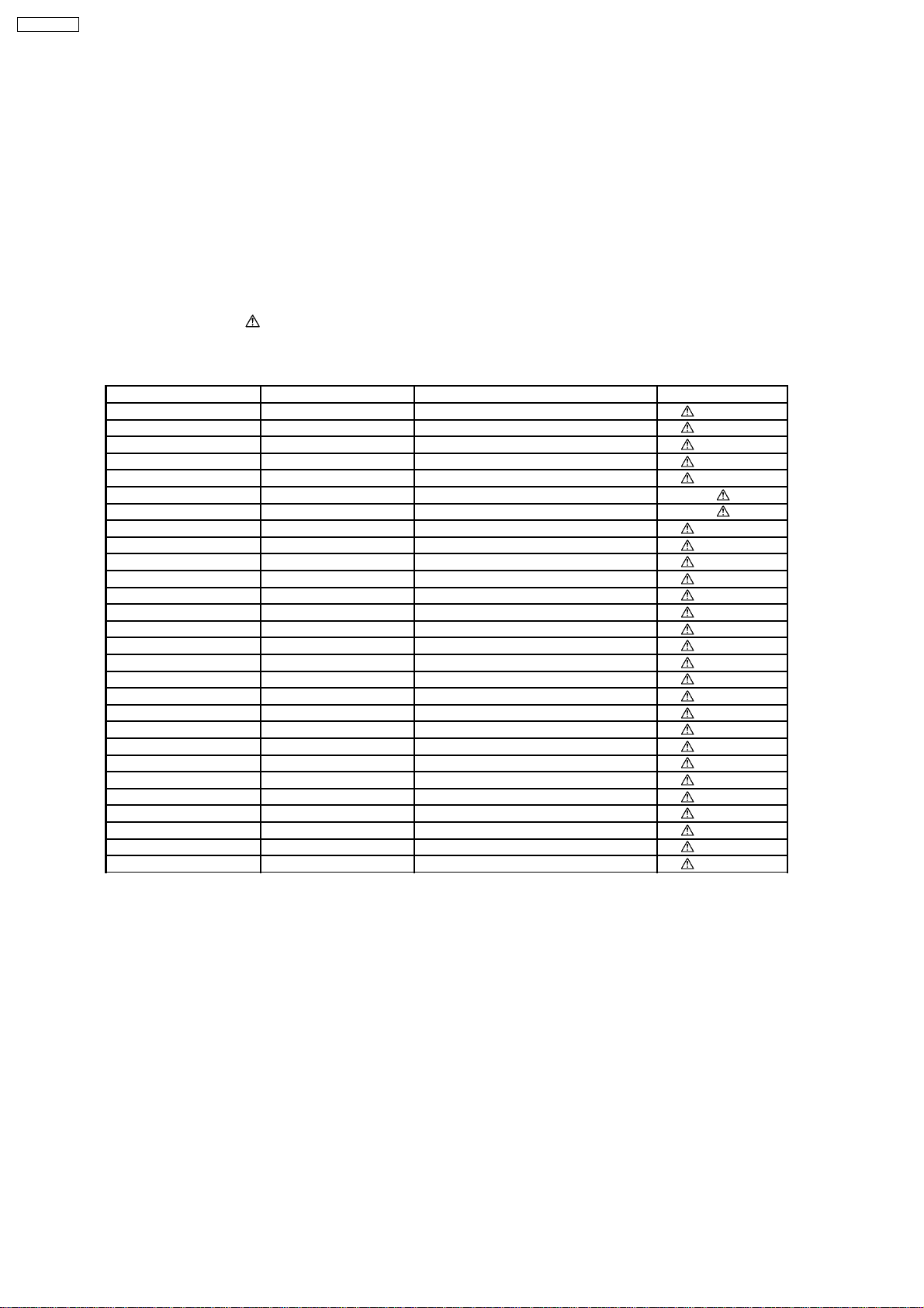
1.4. Safety Parts Information
Safety Parts List:
There are special components used in this equipment which are important for safety.
These parts are marked by
should be replaced with manufacturer’s specified parts to prevent shock, fire or other hazards. Do not modify the original design
without permission of manufacturer.
Ref. No. Part No. Part Name & Description Remarks
14 REXX0640-J BLACK WIRE (SMPS-AC) [M]
15 REXX0641-J RED WIRE (SMPS-AC) [M]
19 RGR0385A-D1 REAR PANEL [M]
30 RKM0603-K TOP CABINET [M]
A2 K2CB2CB00021 AC CORD [M]
PCB16 REPX0622Q SMPS P.C.B [M] (RTL)
PCB17 REPX0622Q AC INLET P.C.B. [M] (RTL)
DZ5701 ERZV10V511CS ZNR [M]
L5701 ELF15N035AN LINE FILTER [M]
L5702 ELF22V035E LINE FILTER [M]
L5703 ELF22V035E LINE FILTER [M]
T5701 ETS42BM19GAC SWITCHING TRANSFORMER [M]
T5751 ETS19AB281AG BACKUP TRANSFORMER [M]
T7001 G4D1A0000094 SWITCHING TRANSFORMER [M]
PC5701 B3PBA0000402 PHOTO COUPLER [M]
PC5702 B3PBA0000402 PHOTO COUPLER [M]
PC5720 B3PBA0000402 PHOTO COUPLER [M]
PC5799 B3PBA0000402 PHOTO COUPLER [M]
F1 K5D802APA008 FUSE [M]
IP7001 K5H7512A0010 IC PROTECTOR [M]
TH5701 D4CAA2R20001 THERMISTOR [M]
TH5860 D4CC11040013 THERMISTOR [M]
P5701 K2AB2B000011 AC INLET [M]
C5700 F1BAF1020020 1000pF [M]
C5701 ECQU2A104MLC 0.1uF [M]
C5702 ECQU2A104MLC 0.1uF [M]
C5703 ECQU2A104MLC 0.1uF [M]
C5704 F1BAF1020020 1000pF [M]
in the Schematic Diagrams & Replacement Parts List. It is essential that these critical parts
Table 1
6

SA-BX500PP
2 Prevention of Electrostatic Discharge (ESD) to
Electrostatically Sensitive (ES) Devices
Some semiconductor (solid state) devices can be damaged easily by static electricity. Such components commonly are called
Electrostatically Sensitive (ES) Devices. Examples of typical ES devices are integrated circuits and some field-effect transistors and
semiconductor “chip” components. The following techniques should be used to help reduce the incidence of component damage
caused by electrostatic discharge (ESD).
1. Immediately before handling any semiconductor component or semiconductor-equipped assembly, drain off any ESD on your
body by touching a known earth ground. Alternatively, obtain and wear a commercially available discharging ESD wrist strap,
which should be removed for potential shock reasons prior to applying power to the unit under test.
2. After removing an electrical assembly equipped with ES devices, place the assembly on a conductive surface such as
aluminum foil, to prevent electrostatic charge buildup or exposure of the assembly.
3. Use only a grounded-tip soldering iron to solder or unsolder ES devices.
4. Use only an anti-static solder removal device. Some solder removal devices not classified as “anti-static (ESD protected)” can
generate electrical charge sufficient to damage ES devices.
5. Do not use freon-propelled chemicals. These can generate electrical charges sufficient to damage ES devices.
6. Do not remove a replacement ES device from its protective package until immediately before you are ready to install it. (Most
replacement ES devices are packaged with leads electrically shorted together by conductive foam, aluminum foil or comparable
conductive material).
7. Immediately before removing the protective material from the leads of a replacement ES device, touch the protective material
to the chassis or circuit assembly into which the device will be installed.
Caution:
Be sure no power is applied to the chassis or circuit, and observe all other safety precautions.
8. Minimize bodily motions when handling unpackaged replacement ES devices. (Otherwise harmless motion such as the
brushing together of your clothes fabric or the lifting of your foot from a carpeted floor can generate static electricity (ESD)
sufficient to damage an ES device).
7
SA-BX500PP
3 About Lead Free Solder (PbF)
3.1. Service caution based on legal restrictions
3.1.1. General description about Lead Free Solder (PbF)
The lead free solder has been used in the mounting process of all electrical components on the printed circuit boards used for this
equipment in considering the globally environmental conservation.
The normal solder is the alloy of tin (Sn) and lead (Pb). On the other hand, the lead free solder is the alloy mainly consists of tin
(Sn), silver (Ag) and Copper (Cu), and the melting point of the lead free solder is higher approx.30 degrees C (86°F) more than that
of the normal solder.
Definition of PCB Lead Free Solder being used
The letter of “PbF” is printed either foil side or components side on the PCB using the lead free solder.
(See right figure)
Service caution for repair work using Lead Free Solder (PbF)
•
• The lead free solder has to be used when repairing the equipment for which the lead free solder is used.
• •
(Definition: The letter of “PbF” is printed on the PCB using the lead free solder.)
•
• To put lead free solder, it should be well molten and mixed with the original lead free solder.
• •
•
• Remove the remaining lead free solder on the PCB cleanly for soldering of the new IC.
• •
•
• Since the melting point of the lead free solder is higher than that of the normal lead solder, it takes the longer time to melt
• •
the lead free solder.
•
• Use the soldering iron (more than 70W) equipped with the temperature control after setting the temperature at 350±30
• •
degrees C (662±86°F).
Recommended Lead Free Solder (Service Parts Route.)
•
• The following 3 types of lead free solder are available through the service parts route.
• •
RFKZ03D01K-----------(0.3mm 100g Reel)
RFKZ06D01K-----------(0.6mm 100g Reel)
RFKZ10D01K-----------(1.0mm 100g Reel)
Note
* Ingredient: tin (Sn), 96.5%, silver (Ag) 3.0%, Copper (Cu) 0.5%, Cobalt (Co) / Germanium (Ge) 0.1 to 0.3%
8
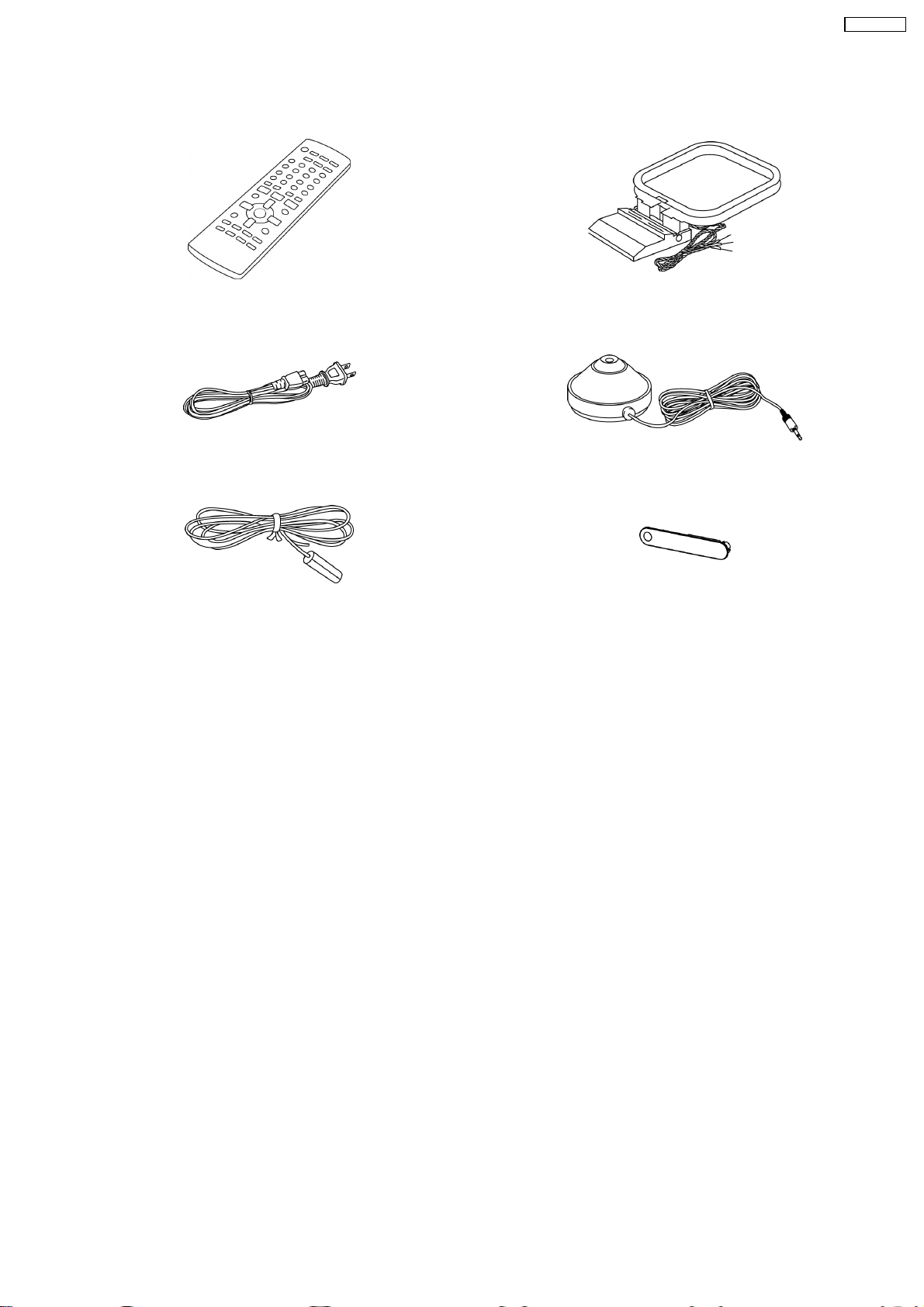
4 Accessories
•
• Note: Refer to “Replacement Parts List” (Section 25) for the part number.
• •
SA-BX500PP
Remote control
AC cord
FM indoor antenna
AM loop antenna
Setup microphone
Front terminal
cover
9
O
O
U
C
H
P
L
A
Y
WIRELESS READY
SURROUND M.ROOM
INPUT SELECTOR
VOLUME
+
_
DTS-HD
MULTI CH
LPCM
BI-AMP
AUX
TUNE
RETURN
AUTO SPEAKER SETUP
-
SETUP
OK
SPEAKERS A
SPEAKERS B
S VIDEO
VIDEO
L - AUDIO - R
SA-BX500PP
5 Operation Procedures
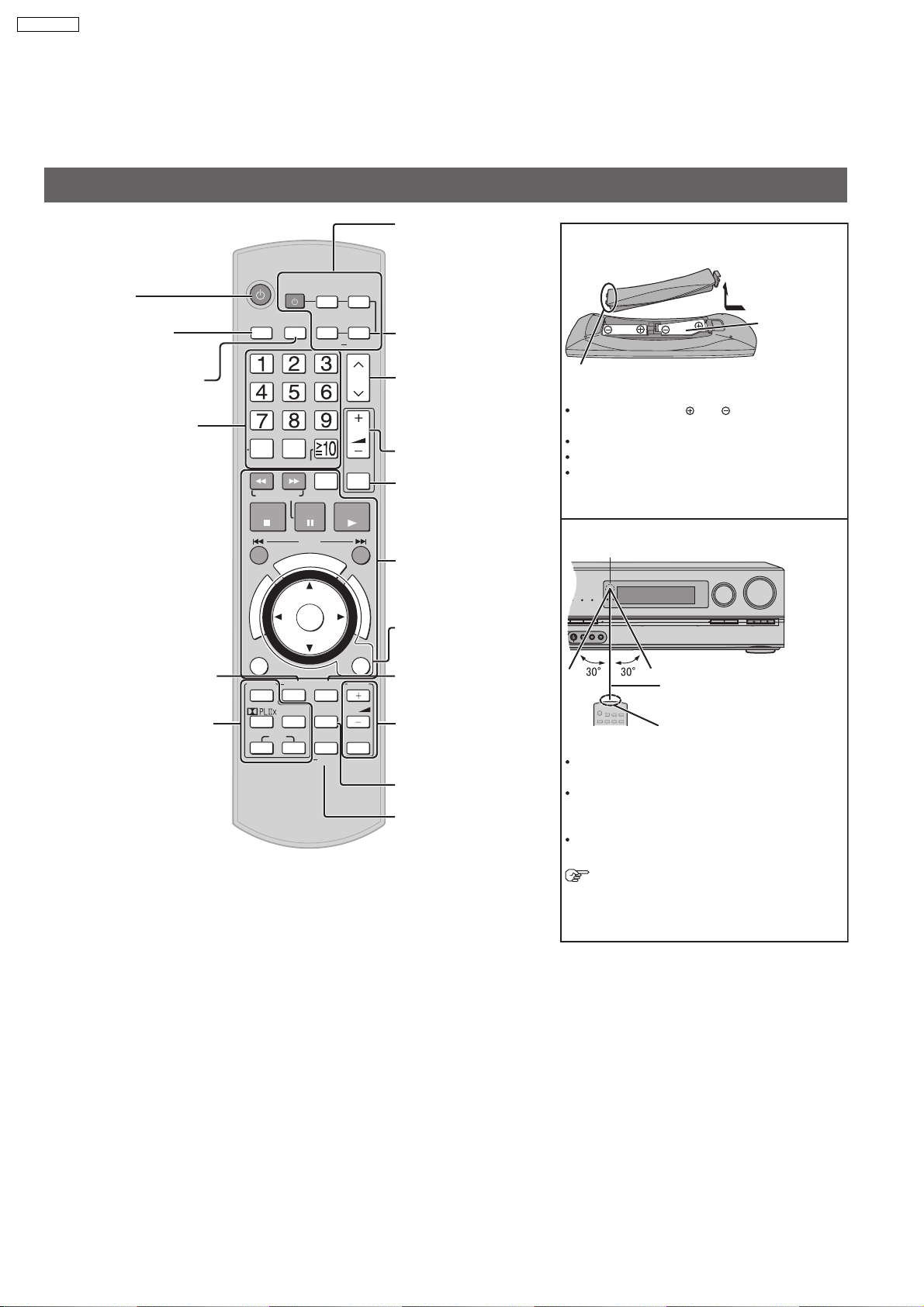
5.1. Remote Control Key Buttons Operations
Remote control
Power button
For selecting input
sources
For switching FM or AM
For inputting channels
TV, cable bo x and satellite
receiver
DVD recorder
Radio
For selecting a track or
chapter
DVD recor der
Blu-ray Disc /DVD player
For inputting frequencies
For confirming speaker
output/For auto speaker
setup/For adjusting
speaker level
For listening to surround
sounds
INPUT
SELECTOR
DIRECT
TUNING
DISC
SEARCH/SLOW
STOP
U
N
E
R
M
O
T
P
A
G
O
I
T
V
A
N
T
C
E
R
I
D
OPTION
SURROUND
OFF
SFC
MUSIC MOVIE
AV
SYSTEM
FM/AM
0
-/--
PAUSE
SKIP
U
O
T
E
N
O
OK
AUTO
TEST
NEO : 6
TV
CABLE
SAT
DRIVE
SELECT
C
H
P
L
SOUND
MENU
DISPLAY
OPTION
PORT
SETUP
RECORDER
DVD
PLAYER
BD/DVD
ANALOG 8CH
CH
VOL
MUTING
PLAY
A
Y
F
U
N
C
T
I
O
N
S
RETURN
TV
VOL
TV/VIDEO
For switching an input
source on and off/
Source switching/
Switching remote
control modes
For playing 8 channels
sources
For selecting a channel
TV, cable box and satellite
receiver
DVD recorder
Radio
For adjusting volumes
For silencing speakers
temporarily
For operating other
equipment
For operating SOUND
MENU/SETUP
For selecting SOUND
MENU
For operating a TV
For c
hanging the
display
For playing an iPod
/For entering
SETUP menu items
Batteries
Press on the tab to open.
(R6/LR6, AA)
Place this side in before the other side
when you close.
Insert so the poles ( and ) match those in the
remote control.
Do not use rechargeable type batteries.
Do not heat or expose to flame.
Do not leave the batteries in an automobile
exposed to direct sunlight for a long period of
time with doors and windows closed.
Use
Remote control signal sensor
About
7 meters (23 feet) or less
when you sit directly in front of
the signal sensor (Exact
distance depends on angles).
Transmission window
Caution
Do not place an object between the signal
sensor and the remote control.
Do not place the signal sensor under direct
sunlight or the strong light of an in
verter
fluorescent lamp.
Keep the transmission window and the units
sensor free from dust.
When you set the unit in a cabinet
The remote controlling range may decrease
depending on the thickness or colours of
glass cabinet doors.
10
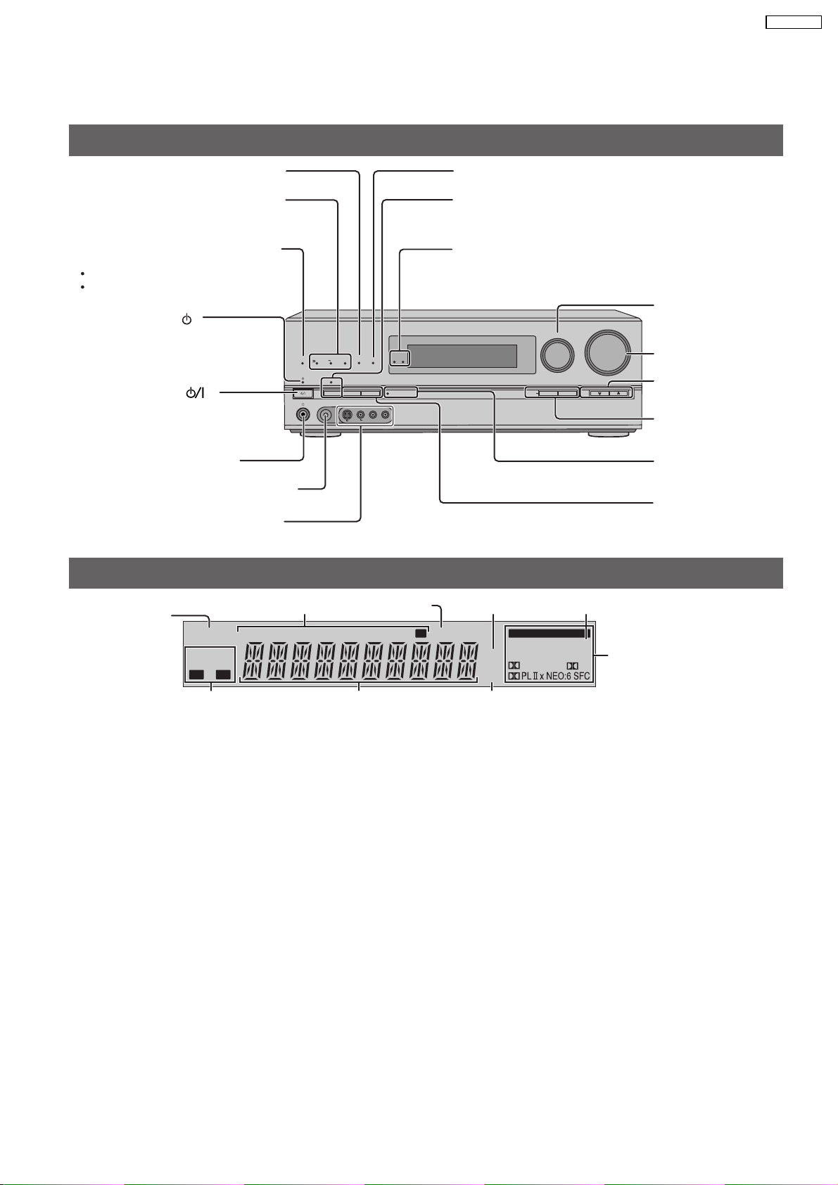
5.2. Main Unit Key Buttons Operations
This unit
SA-BX500PP
Lights on when playing a disc using
multi-channel LPCM format
Lights on when playing a disc using
high definition audio format such as
Blu-ray Disc
Lights on when the following multichannel playback settings are used
When playing multi-channel sources
When using surround effects for twochannel sources , etc.
Standby indicator [ ]
When the unit is connected to the
household AC outlet, this indicator
lights up in standby mode and goes
out when the unit is turned on.
Standby/on switch [ ]
Press to switch the unit from on to
standby mode or vice versa. In standby
mode, the unit is still consuming a
small amount of power.
For connecting headphones
For connecting the setup microphone
For connecting a video camera etc.
Display
Lights on when
2-channel mix is
functioning
2CH MIX
SPEAKERS
BI-WIRE
A B
Radio display
TUNED
MULTI CH
TrueHD
PROCESSING
SETUP MIC
MONO ST
WIRELESS READY
MULTI CH
SURROUND M.ROOM
BI-AMP
LPCM
D+
DTS-HD
SPEAKERS B
SURROUND
SPEAKERS A
AUTO SPEAKER SETUP
AUX
L - AUDIO - R
S VIDEO
VIDEO
Lights on when sleep
timer is set
M
Lights on when BI-AMP is on
For switching the surround playback on
and off (The indicator lights up when the
surround playback is on.)
Lights up under the condition that using the
digital transmitter (SH-FX67) is possible
For selecting input
INPUT SELECTOR
-
SETUP
RETURN
VOLUME
_
OK
TUNE
sources
For adjusting volumes
+
For tuning the radio
For SETUP operations
Lights on during the
auto speaker setup
For selecting front
speakers
Unit display
SLEEP
ft
kHz
MHz
Lights on when PCM FIX is selected
DIGITAL INPUT
DTS 96/24DTS
DIGITAL EX
-ES
PCM
Lights on when the
corresponding digital
EX
source is input
Frequency unit indicatorsGeneral displayDisplays front speakers in use
11
SA-BX500PP
5.3. Using the VIERA Link “HDAVI Control™”
Using the VIERA Link "HDAVI ControlTM"
What is
VIERA Link
VIERA Link "HDAVI Control" ?
TM
is a new name for EZ SyncTM.
VIERA Link "HDAVI Control" is a convenient function that offer s linked operations of this unit, and
a Panasonic TV (VIERA) or DVD recor der (DIGA) under "HDAVI Control". You can use this function
by connecting the equipment with the HDMI cable . See the operating instructions for connected
equipment for operational details.
VIERA Link "HDAVI Control", based on the control functions provided by HDMI which is an industry standard known as HDMI
CEC (Consumer Electronics Control), is a unique function that we have developed and added. As such, its operation with other
manufacturers’ equipment that supports HDMI CEC cannot be guaranteed.
This unit suppor ts "HDAVI Control 1" function.
This standard is compatible with Panasonic’s conventional HDAVI equipment.
Please refer to individual manuals for other manufacturers’ equipment supporting VIERA Link function.
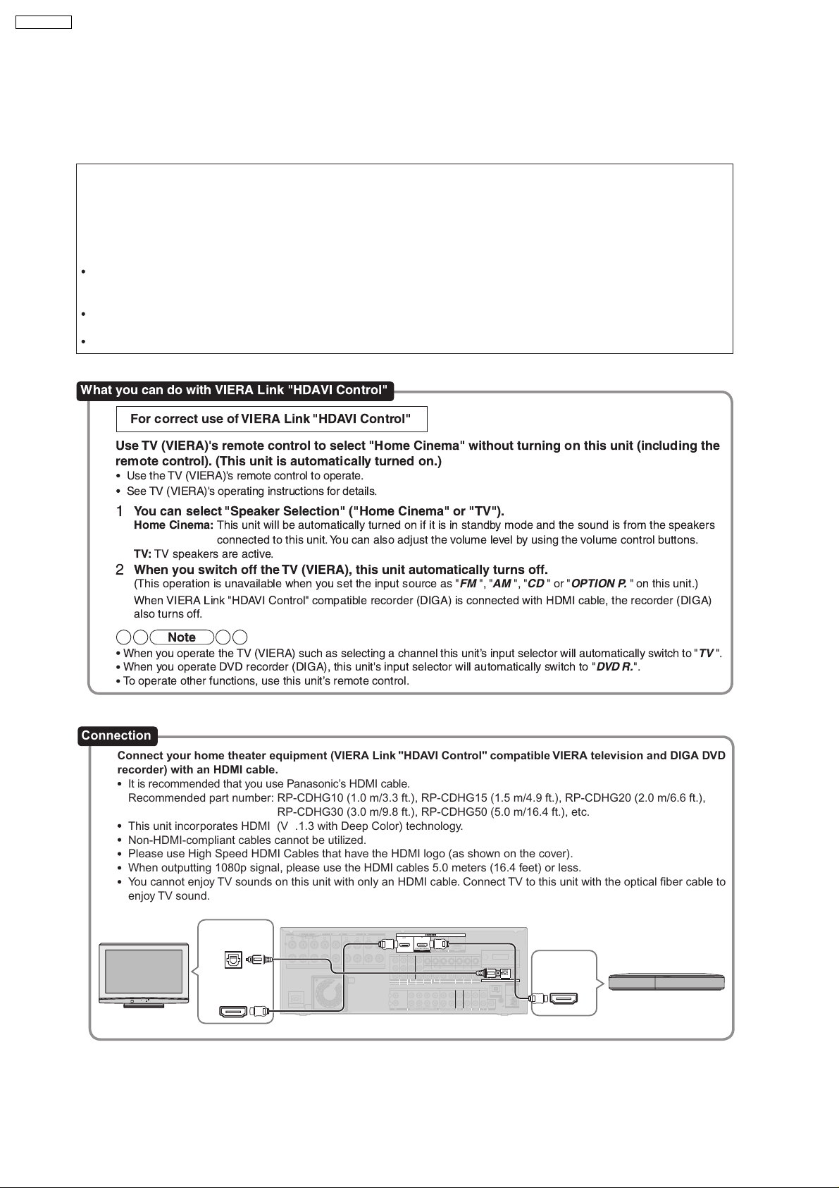
What you can do with VIERA Link "HDAVI Control"
For correct use of VIERA Link "HDAVI Control"
Use TV (VIERA)'s remote control to select "Home Cinema" without turning on this unit (including the
remote control). (This unit is automatically turned on.)
Use the TV (VIERA)'s remote control to operate.
See TV (VIERA)'s operating instructions for details.
You can select "Speaker Selection" ("Home Cinema" or "TV").
1
Home Cinema:
This unit will be automatically turned on if it is in standby mode and the sound is from the speakers
connected to this unit.You can also adjust the volume level by using the volume control buttons.
TV:
TV speakers are active.
When you switch off the TV (VIERA), this unit automatically turns off.
2
(This operation is unavailable when you set the input source as "FM", "AM", "CD"or"
OPTION P.
" on this unit.)
When VIERA Link "HDAVI Control" compatible recorder (DIGA) is connected with HDMI cable, the recorder (DIGA)
also turns off.
Note
When you operate the TV (VIERA) such as selecting a channel this units input selector will automatically switch to "TV".
When you operate DVD recorder (DIGA), this unit's input selector will automatically switch to "
To operate other functions, use this units remote control.
DVD R.
".
Connection
Connect your home theater equipment (VIERA Link "HDAVI Control" compatible VIERA television and DIGA DVD
recorder) with an HDMI cable.
It is recommended that you use Panasonic’s HDMI cable.
Recommended part number: RP-CDHG10 (1.0 m/3.3 ft.), RP-CDHG15 (1.5 m/4.9 ft.), RP-CDHG20 (2.0 m/6.6 ft.),
This unit incorporates HDMI (V .1.3 with Deep Color) technology.
Non-HDMI-compliant cables cannot be utilized.
Please use High Speed HDMI Cables that have the HDMI logo (as shown on the cover).
When outputting 1080p signal, please use the HDMI cables 5.0 meters (16.4 feet) or less.
You cannot enjoy TV sounds on this unit with only an HDMI cable. Connect TV to this unit with the optical fiber cable to
enjoy TV sound.
Digital audio
out (optical)
HDMI IN
TV (VIERA)
RP-CDHG30 (3.0 m/9.8 ft.), RP-CDHG50 (5.0 m/16.4 ft.), etc.
Rear panel
FRONT A
CENTER
FRONT B
FRONT A FRONT B CENTER
BI-WIRE
LF HF
R
L
A OR B / BI-WIRE (4-16 W EACH SPEAKER) A AND B (6-16 W EACH SPEAKER)
A
C IN~
SURROUND SURROUND BACK
SURROUND
SURROUND BACK
L
R
L L
RR
(6-16 W EACH SPEAKER)
SPEAKERS
Y
B
P
R
P
OUT
(DVD RECORDER)
TV MONITOR
L
R
IN
CD
IN IN
OUT
(DVD RECORDER)
HDMI 1
COMPONENT VIDEO
TV MONITOR
IN
IN
IN
(CABLE/SAT)
TV MONITOR
DVD PLAYER)
12
3
CENTER
SURROUND BACK
SURROUND
SUBWOOFER
BD/DVD PLAYER / ANALOG 8CH IN DVD RECORDER
(BD/DVD PLAYER)
OUT OUT
BD/
DVD PLAYER
OUT
BD/(BD/
DVD PLAYER
FRONT
HDMI 2 HDMI 3
IN
DVD RECORDER
IN
OUT
DVD RECORDER
AUDIO
OUT
IN
(CABLE/SAT)
S VIDEO
IN IN IN IN
VCR
CABLE/SAT
VIDEO
IN IN IN
VCR
CABLE/SAT
IN IN
IN IN IN
CABLE/SAT
VCR
GAME
(DVD RECORDER) (BD/DVD PLAYER)
OPTICAL 2 OPTICAL 3 COAXIAL
OPTICAL 1
DIGITAL IN
IN
GAME
DC OUT 5V
500mA MAX
OPTION V 1
LOOP ANT
GND
OUT
TV
GAME
SUBWOOFER
HDMI
(TV)
(CD)
OUT
FM ANT
75
W
LOOP
EXT
AM ANT
DVD recorder
(DIGA)
12
5.4. Main Unit Connections
SURROUND SURROUND BACK
OUT
IN IN
CD
BD/DVD PLAYER / ANALOG 8CH IN DVD RECORDER
VCR
CABLE/SAT
GAME
TV
AUDIO
SURROUND BACK
SURROUND
FRONT
SUBWOOFER
OUT
IN IN
IN
(DVD RECORDER)
(BD/DVD PLAYER)
(CABLE/SAT)
HDMI 1
HDMI 2 HDMI 3
SURROUND
SURROUND BACK
S VIDEO
COMPONENT VIDEO
L
R
IN IN IN
IN
OUT
IN
IN
OUT
IN IN IN
IN
TV MONITOR
TV MONITOR
DVD RECORDER
VCR
CABLE/SAT
GAME
DVD PLAYER
BD/(BD/
DVD PLAYER)
(DVD RECORDER)
(CABLE/SAT)
12
3
(DVD RECORDER)
(BD/DVD PLAYER)
(TV)
(CD)
OPTICAL 1
OPTICAL 2 OPTICAL 3 COAXIAL
SUBWOOFER
Y
P
B
P
R
IN
OUT OUT
IN IN IN IN
TV MONITOR
DVD RECORDER
VCR
CABLE/SAT
GAME
DVD PLAYER
BD/
OUT
CENTER
IN
IN
FM ANT
AM ANT
LOOP
EXT
75
W
R
R
L L
LOOP ANT
GND
VIDEO
OUT
DIGITAL IN
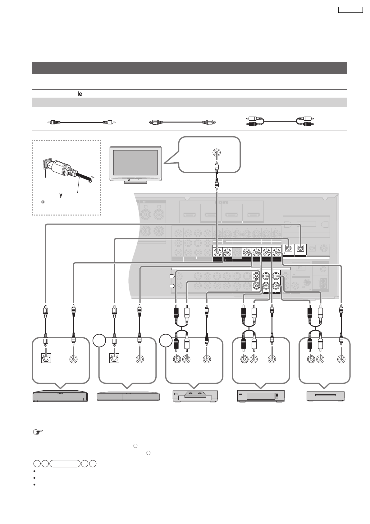
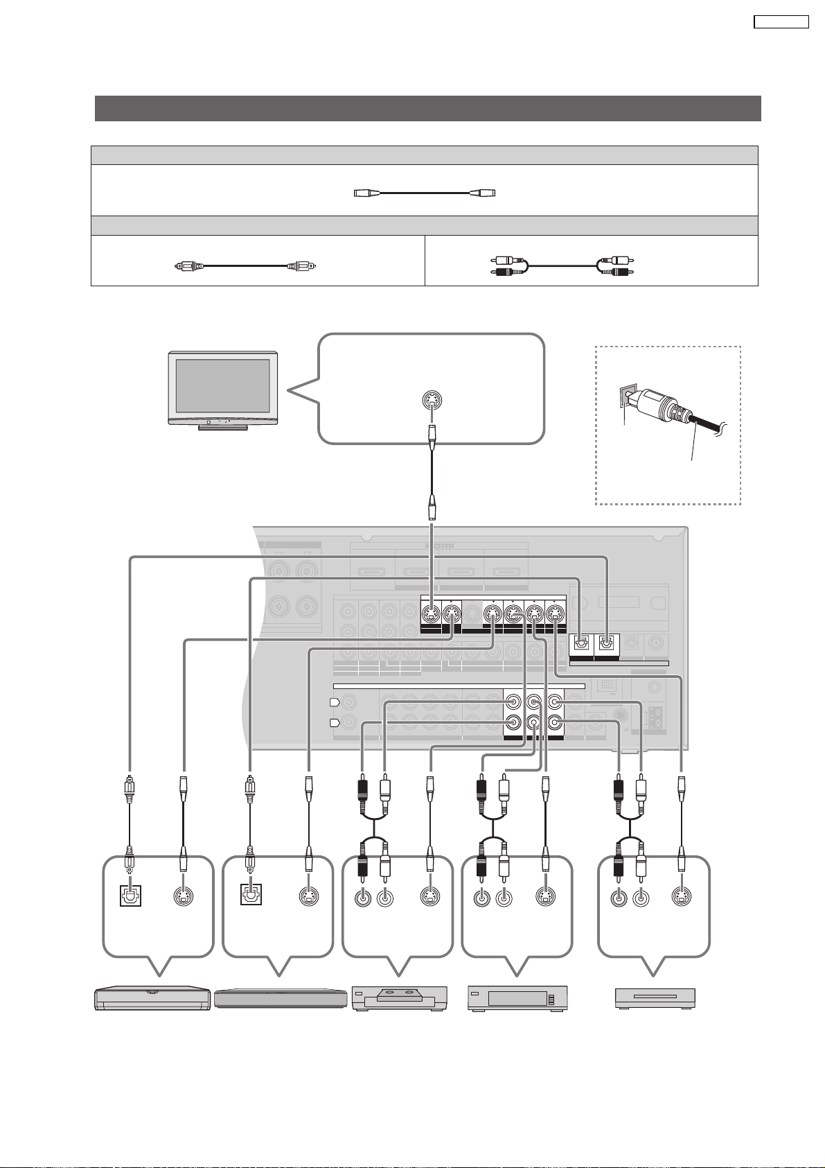
5.4.1. Video & Audio Terminals
Basic connections
Connecting cables to video and audio terminals (Connecting equipment without HDMI terminal)
Connection cab
Video connection cable (not included)
le
Video cable Audio cable
Optical fiber cable (not included)
Stereo connection cable
(not included)
White (L)
Red (R)
SA-BX500PP
Connecting the optical
fiber cable
Note the
shape and fit
it correctl
into the
y
Do not
bend!
terminal.
TV
CHAQUE)
Class2 wiring
VIDEO IN
DC OUT/SORTIE C.C.
5V 500mA MAX
OPTION V.1
Rear panel
1 2
Digital audio
out (optical)
DVD player
To connect a DVD recorder with built-in VCR
(When the DVD recorder has DVD/VHS terminals, make the following connections.)
Connect the DVD output terminal as shown above.
Connect the DVD/VHS output terminal as shown above.
When you make HDMI connections this connection is not necessary.
The input video signal can be sent out through an output terminal of the same type only.
You can change the digital input terminal setting according to the equipment to connect.
Note
VIDEO
OUT
Digital audio
out (optical)
DVD recorderBlu-ray Disc/
VIDEO
1
OUT
2
(R) (L)
Audio out
VCR
13
VIDEO
OUT
Audio out
Cable box or
satellite receiver
(R) (L)
VIDEO
OUT
(R) (L)
Audio out
Game
VIDEO
OUT
SURROUND SURROUND BACK
OUT
IN IN
CD
BD/DVD PLAYER / ANALOG 8CH IN DVD RECORDER
VCR
CABLE/SAT
GAME
AUDIO
SURROUND BACK
SURROUND
FRONT
SUBWOOFER
OUT
IN IN
IN
(DVD RECORDER)
(BD/DVD PLAYER)
(CABLE/SAT)
HDMI 1
HDMI 2 HDMI 3
SURROUND
SURROUND BACK
S VIDEO
COMPONENT VIDEO
L
R
IN IN IN
IN
OUT
IN
IN
OUT
OUT
IN IN IN
IN
TV MONITOR
TV MONITOR
DVD RECORDER
VCR
CABLE/SAT
GAME
DVD PLAYER
BD/
(BD/
DVD PLAYER)
(DVD RECORDER)
(CABLE/SAT)
12
3
(DVD RECORDER)
(BD/DVD PLAYER)
(CD)
OPTICAL 1
OPTICAL 2 COAXIAL
SUBWOOFER
Y
P
B
P
R
IN
OUT OUT
IN IN IN IN
TV MONITOR
DVD RECORDER
VCR
CABLE/SAT
GAME
DVD PLAYER
BD/
OUT
CENTER
IN
IN
FM ANT
AM ANT
LOOP
EXT
75
W
R
L L
LOOP ANT
GND
VIDEO
SA-BX500PP
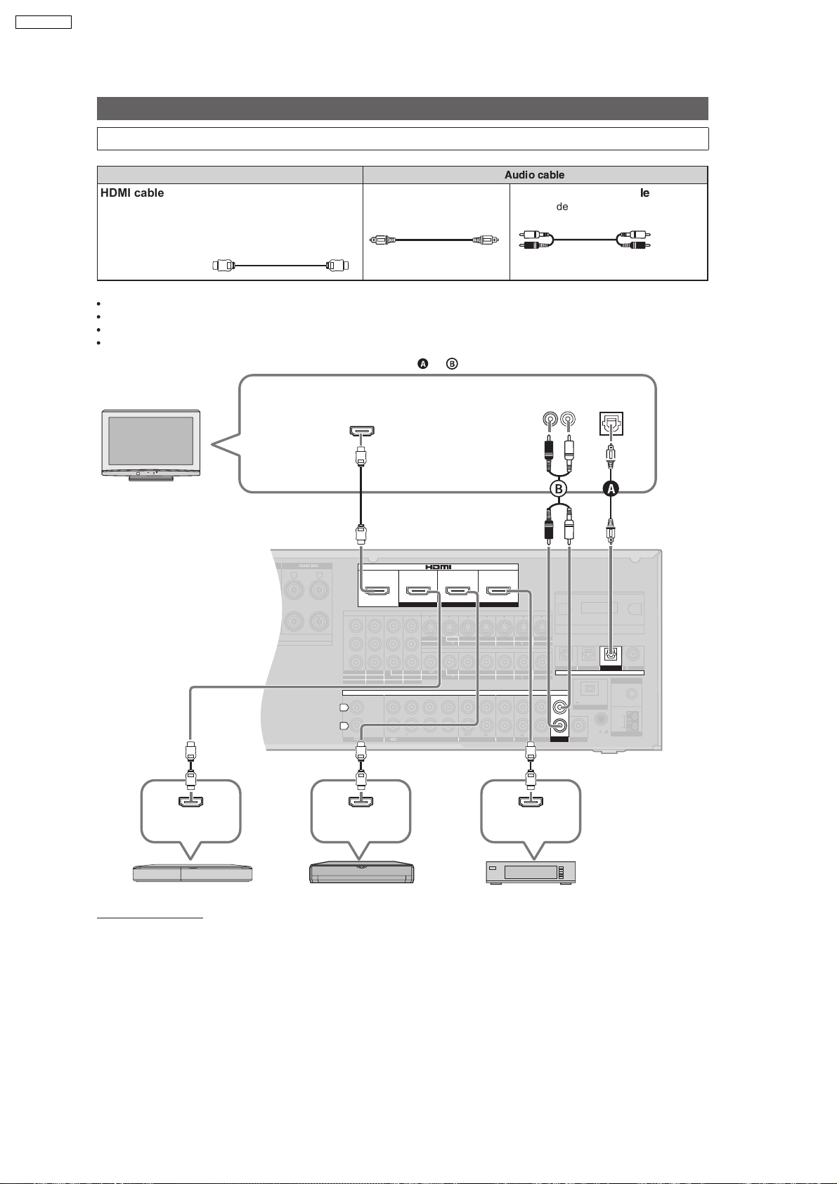
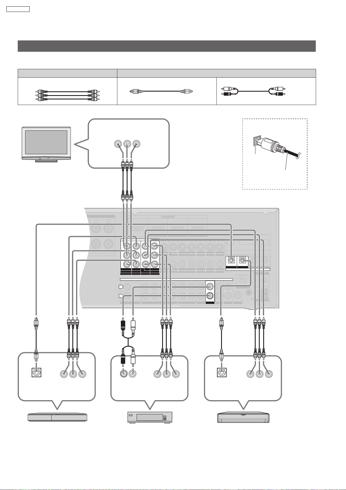
5.4.2. Connecting equipment with HDMI Terminal
Basic connections
Connecting equipment with HDMI terminal
Connection cable
Video and Audio cable
HDMI cable
Recommended part number:
RP-CDHG10 (1.0 m/3.3 ft.), RP-CDHG15 (1.5 m/4.9 ft.),
RP-CDHG20 (2.0 m/6.6 ft.), RP-CDHG30 (3.0 m/9.8 ft.),
RP-CDHG50 (5.0 m/16.4 ft), etc.
HDMI cable notes
It is recommended that you use Panasonics HDMI cable.
This unit incorporates HDMI (V .1.3 with Deep Color) technology.
Please use High Speed HDMI Cables that have the HDMI logo (as shown on the cover).
When outputting 1080p signal, please use the HDMI cables 5.0 meters (16.4 feet) or less.
(not included)
Optical fiber cable
(not included)
To enjoy TV with surround sound, make connection or shown below according to your equipment.
Audio cable
Stereo connection cab
(not included)
le
White (L)
Red (R)
TV
Rear panel
CHAQUE)
Class2 wiring
HDMI input
Audio out
(R) (L)
DC OUT/SORTIE C.C.
OPTION V.1
TV
Digital audio
out (optical)
(TV)
OPTICAL 3
DIGITAL IN
5V 500mA MAX
HDMI
Video/Audio out
DVD recorder
HDMI
Video/Audio out
Blu-ray Disc/DVD player Cable box, satellite receiver, etc.
HDMI
Video/Audio out
HDMI connection
The HDMI input terminal on the unit s rear is made to specifications that presume connection of a DVD recorder / Blu-ray Disc /
DVD player etc. When other equipment is connected, sounds may not come out of the unit, or pictures shown on the equipment (TV)
connected to the HDMI output terminal may be disrupted.
14
5.4.3. S Video and audio Terminals
SURROUND SURROUND BACK
OUT
IN IN
CD
BD/DVD PLAYER / ANALOG 8CH IN DVD RECORDER
VCR
CABLE/SAT
GAME
TV
AUDIO
SURROUND BACK
SURROUND
FRONT
SUBWOOFER
OUT
IN IN
IN
(DVD RECORDER)
(BD/DVD PLAYER)
(CABLE/SAT)
HDMI 1
HDMI 2 HDMI 3
SURROUND
SURROUND BACK
S VIDEO
COMPONENT VIDEO
L
R
IN IN IN
IN
OUT
IN
IN
OUT
OUT
IN IN IN
IN
TV MONITOR
TV MONITOR
DVD RECORDER
VCR
CABLE/SAT
GAME
DVD PLAYER
BD/(BD/
DVD PLAYER)
(DVD RECORDER)
(CABLE/SAT)
12
3
(DVD RECORDER)
(BD/DVD PLAYER)
(TV)
(CD)
OPTICAL 1
OPTICAL 2 OPTICAL 3 COAXIAL
SUBWOOFER
Y
P
B
P
R
IN
OUT OUT
IN IN IN IN
TV MONITOR
DVD RECORDER
VCR
CABLE/SAT
GAME
DVD PLAYER
BD/
(6-16 W EACH SPEAKER)
OUT
CENTER
IN
IN
FM ANT
AM ANT
OPTION V 1
LOOP
EXT
DC OUT 5V
500mA MAX
75
W
RR
L L
LOOP ANT
GND
VIDEO
DIGITAL IN
Connecting cables to S video and audio terminals
Connection cable
S VIDEO connection cab
Optical fibre cable
le (not included)
(not included)
TV
Video cable
Audio cable
Stereo connection cable
S VIDEO IN
(not included)
SA-BX500PP
White (L)
Red (R)
Connecting the optical
fibre cable
Rear panel
Note the
shape and fit
it correctly
into the
terminal.
Do not
bend!
Digital audio
S VIDEO
out (optical)
DVD player
Digital audio
out (optical)
DVD recorderBlu-ray Disc/
OUT
S VIDEO
OUT
(R) ( L)
Audio out
S VIDEO
OUT
VCR
15
(R ) ( L)
Audio out
Cable box or
S VIDEO
OUT
(R) ( L)
Audio out
Game
S VIDEO
OUT
satellite receiver
SURROUND SURROUND BACK
OUT
IN IN
CD
BD/DVD PLAYER / ANALOG 8CH IN DVD RECORDER
VCR
CABLE/SAT
GAME
TV
AUDIO
SURROUND BACK
SURROUND
FRONT
SUBWOOFER
OUT
IN IN
IN
(DVD RECORDER)
(BD/DVD PLAYER)
(CABLE/SAT)
HDMI 1
HDMI 2 HDMI 3
SURROUND
SURROUND BACK
S VIDEO
COMPONENT VIDEO
L
R
IN IN IN
IN
OUT
IN
IN
OUT
OUT
IN IN IN
IN
TV MONITOR
TV MONITOR
DVD RECORDER
VCR
CABLE/SAT
GAME
DVD PLAYER
BD/(BD/
DVD PLAYER)
(DVD RECORDER)
(CABLE/SAT)
12
3
(DVD RECORDER)
(BD/DVD PLAYER)
(TV)
(CD)
OPTICAL 1
OPTICAL 2 OPTICAL 3 COAXIAL
SUBWOOFER
Y
P
B
P
R
IN
OUT OUT
IN IN IN IN
TV MONITOR
DVD RECORDER
VCR
CABLE/SAT
GAME
DVD PLAYER
BD/
(6-16 W EACH SPEAKER)
OUT
CENTER
IN
IN
FM ANT
AM ANT
OPTION V 1
LOOP
EXT
DC OUT 5V
500mA MAX
75
W
RR
L L
LOOP ANT
GND
VIDEO
DIGITAL IN
SA-BX500PP
5.4.4. Component and audio terminals
Connecting cables to component and audio terminals
The component video terminals can produce more accurate colours than the S video terminals.
Connection cable
Video cable Audio cable
Video connection cable (not included)
Optical fibre cable (not included) Stereo connection cable (not included)
White (L)
Red (R)
TV
Rear panel
COMPONENT
VIDEO IN
YPBP
R
Connecting the optical
fibre cable
Note the
shape and fit
it correctly
into the
Do not
bend!
terminal.
Digital audio
out (optical)
YPBP
COMPONENT
VIDEO OUT
DVD recorder Blu-ray Disc/
R
(R) (L)
Audio out
YPBP
COMPONENT
VIDEO OUT
Cable box or
satellite receiver
R
16
YPBP
Digital audio
out (optical)
COMPONENT
VIDEO OUT
DVD player
R
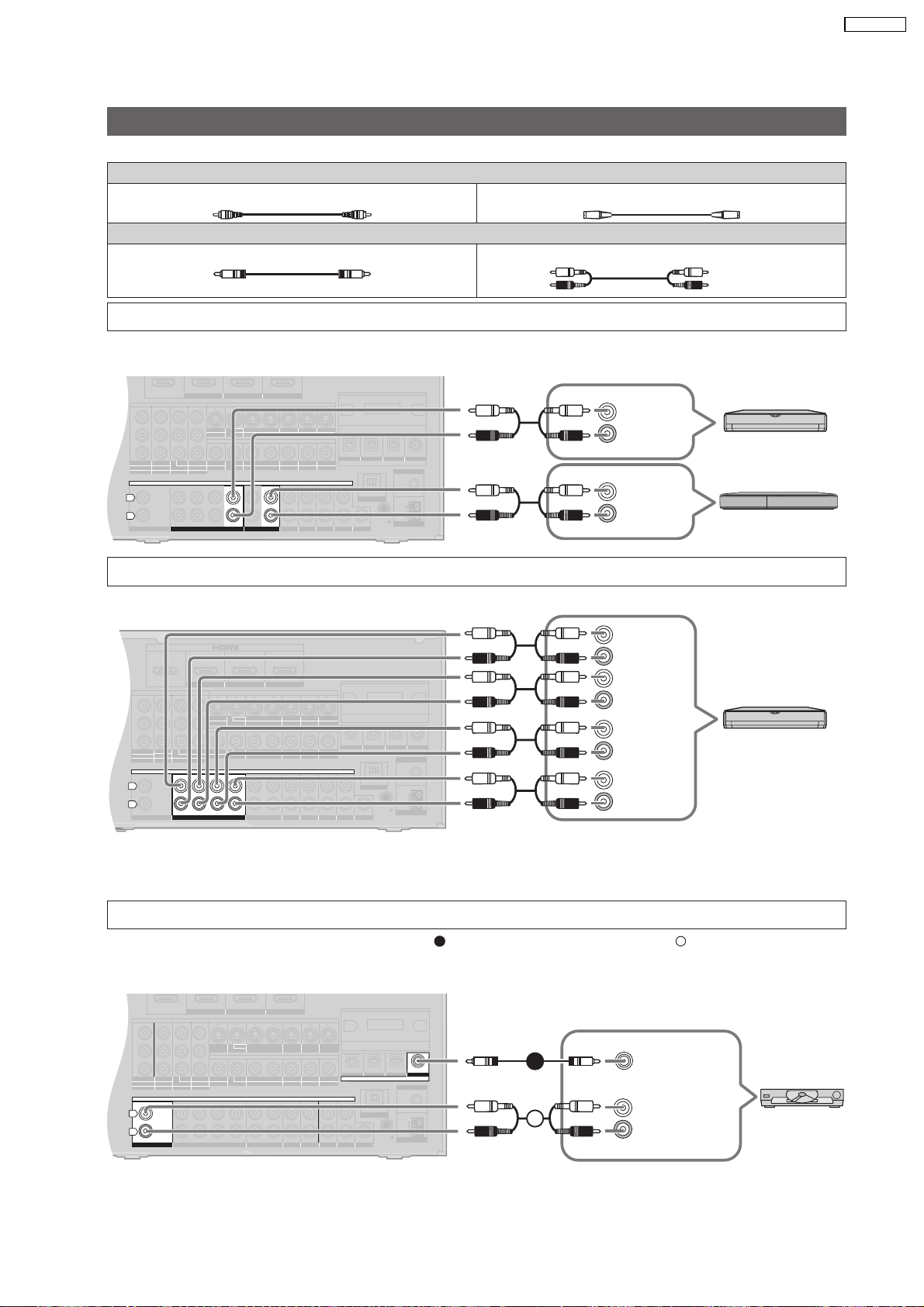
5.4.5. Other connections
OUT
IN IN
CD
BD/DVD PLAYER / ANALOG 8CH IN DVD RECORDER
VCR
CABLE/SAT
GAME
TV
AUDIO
SURROUND BACK
SURROUND
FRONT
SUBWOOFER
(DVD RECORDER)
(BD/DVD PLAYER)
(CABLE/SAT)
HDMI 1
HDMI 2 HDMI 3
S VIDEO
COMPONENT VIDEO
IN IN IN
IN
OUT
IN
IN
OUT
OUT
IN IN IN
IN
TV MONITOR
TV MONITOR
DVD RECORDER
VCR
CABLE/SAT
GAME
DVD PLAYER
BD/(BD/
DVD PLAYER)
(DVD RECORDER)
(CABLE/SAT)
12
3
(DVD RECORDER) (BD/DVD PLAYER)
(TV)
OPTICAL 1
OPTICAL 2 OPTICAL 3
SUBWOOFER
Y
P
B
P
R
IN
OUT OUT
IN IN IN IN
TV MONITOR
DVD RECORDER
VCR
CABLE/SAT
GAME
DVD PLAYER
BD/
OUT
CENTER
IN
IN
FM ANT
AM ANT
OPTION V 1
LOOP
EXT
DC OUT 5V
500mA MAX
75
W
LOOP ANT
GND
VIDEO
L
R
DIGITAL IN
(CD)
COAXIAL
OUT
IN IN
CD
BD/DVD PLAYER / ANALOG 8CH IN DVD RECORDER
VCR
CABLE/SAT
GAME
TV
AUDIO
SURROUND BACK
SURROUND
FRONT
SUBWOOFER
(DVD RECORDER)
(BD/DVD PLAYER)
(CABLE/SAT)
HDMI 1
HDMI 2 HDMI 3
S VIDEO
COMPONENT VIDEO
L
R
IN IN IN
IN
OUT
IN
IN
OUT
OUT
IN IN IN
IN
TV MONITOR
TV MONITOR
DVD RECORDER
VCR
CABLE/SAT
GAME
DVD PLAYER
BD/(BD/
DVD PLAYER)
(DVD RECORDER)
(CABLE/SAT)
12
3
DIGITAL IN
(DVD RECORDER)
(BD/DVD PLAYER)
(TV)
(CD)
OPTICAL 1
OPTICAL 2 OPTICAL 3 COAXIAL
SUBWOOFER
Y
P
B
P
R
IN
OUT OUT
IN IN IN IN
TV MONITOR
DVD RECORDER
VCR
CABLE/SAT
GAME
DVD PLAYER
BD/
OUT
CENTER
IN
IN
FM ANT
AM ANT
OPTION V 1
LOOP
EXT
DC OUT 5V
500mA MAX
75
W
LOOP ANT
GND
VIDEO
CK
OUT
IN IN
CD
BD/DVD PLAYER / ANALOG 8CH IN DVD RECORDER
VCR
CABLE/SAT
GAME
TV
AUDIO
SURROUND BACK
SURROUND
FRONT
SUBWOOFER
OUT
IN IN
IN
(DVD RECORDER)
(BD/DVD PLAYER)
(CABLE/SAT)
HDMI 1
HDMI 2 HDMI 3
K
S VIDEO
COMPONENT VIDEO
L
R
IN IN IN
IN
OUT
IN
IN
OUT
OUT
IN IN IN
IN
TV MONITOR
TV MONITOR
DVD RECORDER
VCR
CABLE/SAT
GAME
DVD PLAYER
BD/(BD/
DVD PLAYER)
(DVD RECORDER)
(CABLE/SAT)
12
3
DIGITAL IN
(DVD RECORDER) (BD/DVD PLAYER)
(TV)
(CD)
OPTICAL 1
OPTICAL 2 OPTICAL 3 COAXIAL
SUBWOOFER
Y
P
B
P
R
IN
OUT OUT
IN IN IN IN
TV MONITOR
DVD RECORDER
VCR
CABLE/SAT
GAME
DVD PLAYER
BD/
OUT
CENTER
IN
IN
FM ANT
AM ANT
OPTION V 1
LOOP
EXT
DC OUT 5V
500mA MAX
75
W
L
LOOP ANT
GND
VIDEO
Other connections
Connection cable
Video connection cable
Coaxial cable
(not included)
To enjoy analogue sounds
Rear panel
(not included)
Video cable
S VIDEO connection cab
Audio cable
Stereo phono cab
le (not included)
(not included)
le
(L) AUDIO
(R) OUT
SA-BX500PP
White (L)
Red (R)
Blu-ray Disc/
DVD player
(L) AUDIO
(R) OUT
DVD recorder
To enjoy high-quality analogue sounds (Analogue 8-channel connections)
Rear panel
CENTER
SUBW
OOFER
(
L) SURR
OUND
(R)
B ACK
(L)
OUND
(R)
SURR
Blu-ray Disc/DVD
player etc.
(L)
FRONT
(R)
To connect the unit to a CD player
Make either digital audio (COAXIAL) output connections ( ) or analogue audio output connections ( )according to your
A
equipment and preference.
Rear panel
B
A
17
B
AUDIO OUT
AXIAL)
(CO
(L) AUDIO
(R) OUT
CD player
DIGITAL
OUT
IN IN
CD
BD/DVD PLAYER / ANALOG 8CH IN DVD RECORDER
VCR
CABLE/SAT
GAME
TV
AUDIO
SURROUND BACK
SURROUND
FRONT
SUBWOOFER
OUT
IN IN
IN
(DVD RECORDER)
(BD/DVD PLAYER)
(CABLE/SAT)
HDMI 1
HDMI 2 HDMI 3
COMPONENT VIDEO
L
R
IN IN IN
IN
OUT
IN
IN
OUT
OUT
IN IN IN
IN
TV MONITOR
TV MONITOR
DVD RECORDER
VCR
CABLE/SAT
GAME
DVD PLAYER
BD/(BD/
DVD PLAYER)
(DVD RECORDER)
(CABLE/SAT)
12
3
DIGITAL IN
(DVD RECORDER)
(BD/DVD PLAYER)
(TV)
(CD)
OPTICAL 1
OPTICAL 2 OPTICAL 3 COAXIAL
SUBWOOFER
Y
P
B
P
R
IN
OUT
OUT
IN IN IN IN
TV MONITOR
DVD RECORDER
VCR
CABLE/SAT
GAME
DVD PLAYER
BD/
OUT
CENTER
IN
IN
FM ANT
AM ANT
OPTION V 1
LOOP
EXT
DC OUT 5V
500mA MAX
75
W
L
LOOP ANT
GND
VIDEO
S VIDEO
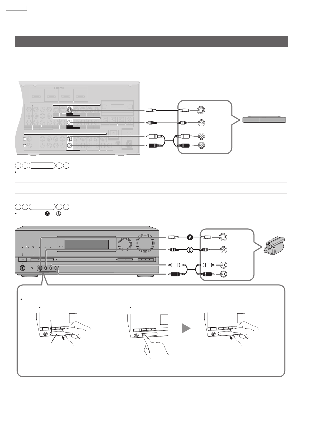
SA-BX500PP
Other connections
To connect the unit for audio or picture recording
You can record audio or pictures to the equipment connected to DVD recorder output terminal (AUDIO, VIDEO, S VIDEO).
Rear panel
S VIDEO
IN
DVD recor der , etc.
VIDEO IN
AUDIO
(L)
(R) IN
Note
Connect the recording unit and source unit using the same cable.
To connect the unit to a video camera etc.
These terminals are convenient for equipment you want to connect only temporarily.
Note
Use a cable, or that belongs to the same type as the video cable you used for connecting the unit to your TV.
PROCESSING
INPUT SELECTOR
WIRELESS READY
MULTI CH
MULTI CH
TrueHD
D+
DTS-HD
SURROUND
SPEAKERS A
SETUP MIC
S VIDEO
SURROUND M.ROOM
BI-AMP
LPCM
SPEAKERS B
AUX
VIDEO
AUTO SPEAKER SETUP
L - AUDIO - R
-
SETUP
RETURN
VOLUME
_
OK
TUNE
+
S VIDEO
OUT
VIDEO
OUT
AUDIO
(L)
(R) OUT
Video
camera
etc.
How to attach or remove the front terminal cover
Attaching the cover is recommended to protect terminals when not in use.
To attach To remove
The dent
Terminal cover
Place the dent on the left to insert. Press the dent. Hold the protrusion to remove.
18
5.4.6. For speakers
BI-WIRE
LF HF
L
R
FRONT A
FRONT B
CENTER
SURROUND SURROUND BACK
CD
FRONT A FRONT B CENTER
SURROUND
SURROUND BACK
L
R
IN
A
C IN~
OUT
TV MONITOR
(DVD RECORDER)
Y
P
B
P
R
R
L
RR
L L
BI-WIRE
LF HF
L
R
FRONT A
FRONT B
CENTER
SURROUND SURROUND BACK
CD
FRONT A FRONT B CENTER
SURROUND
SURROUND BACK
L
R
IN
A
C IN~
OUT
TV MONITOR
(DVD RECORDER)
Y
P
B
P
R
R
L
RR
L L
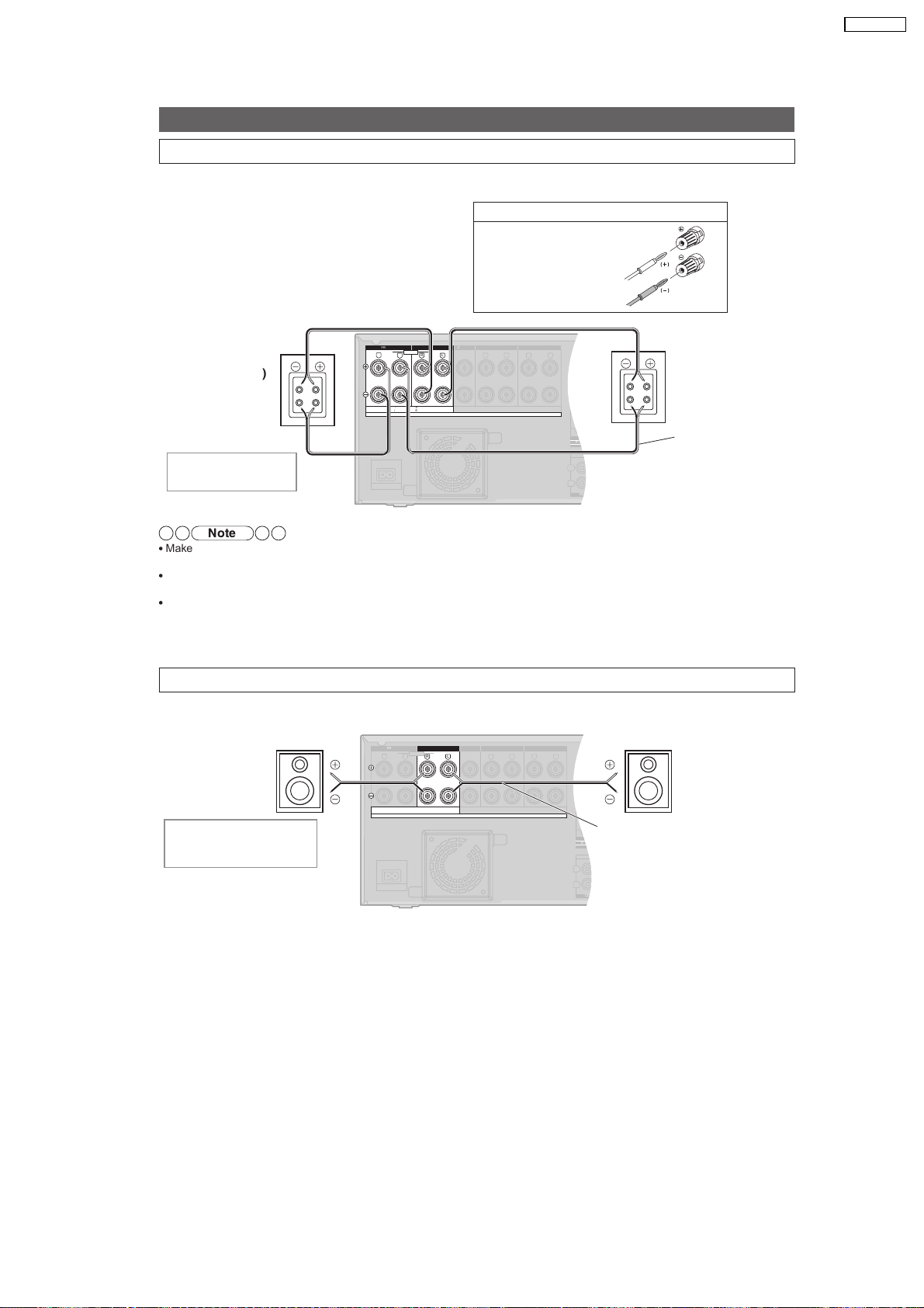
Connecting other speakers
To connect bi-wire speakers
Make sure to select YES in Making bi-wire setting when you connect the unit to bi-wire speakers. The speakers
do not produce adequate sounds unless you make this setting.
SA-BX500PP
If using 4-mm plug
Turn speaker terminals
clockwise and tighten
them before inserting
plugs into their holes.
Rear panel
HF
LF
Front speaker (L)
Rear view
Speaker cable
Front speaker (R
Rear view
HF
)
A OR B/BI-WIRE : 4-8 W / EACH SPEA KER ( CHAQUE)
A AND B : 6-8 W / EACH SPEA KER (CHA QUE)
SPEAKERS
6-8 W / EACH SPEAKER (CHAQUE)
HAUT-PARLEURS
Class2 wiring
LF
(not included)
Speaker impedance
BI-WIRE: 4 to 8
Note
Make sure to connect speakers HF terminals with the unit s FRONT B terminals, and speakers LF terminals with the unit s
FRONT A terminals.
Different amps for high frequency and low frequency signals produce BI-AMP stereo sounds that are clearer and higher in audio
quality when you play on 2 channels sources containing analog audio and 2-channel PCM signals.
When connecting speakers with the impedance of 4 , make sure to set 4 OHMS in Setting the speaker impedance
To connect a second pair of front speakers (SPEAKERS B)
Make the following connections when you wish to install a second pair of speakers in another room and enjoy music there.
Rear panel
Front speaker (R)
Front speaker (L)
Speaker impedance
Front A or B: 4 to 8
Front A and B: 6 to 8
A OR B/BI-WIRE : 4-8 W / EACH SPEA KER ( CHAQUE)
A AND B : 6-8 W / EACH SPEA KER (CH AQUE)
SPEAKERS
19
HAUT-PARLEURS
6-8 W / EACH SPEAKER (CHAQUE)
Class2 wiring
Speaker cable
(not included)
OUND BACK
OUT
IN IN
CD
BD/DVD PLAYER / ANALOG 8CH IN DVD RECORDER
VCR
CABLE/SAT
GAME
TV
AUDIO
SURROUND BACK
SURROUND
FRONT
SUBWOOFER
OUT
IN IN
IN
(DVD RECORDER)
(BD/DVD PLAYER)
(CABLE/SAT)
HDMI 1
HDMI 2 HDMI 3
ND BACK
S VIDEO
COMPONENT VIDEO
L
R
IN IN IN
IN
OUT
IN
IN
OUT
OUT
IN IN IN
IN
TV MONITOR
TV MONITOR
DVD RECORDER
VCR
CABLE/SAT
GAME
DVD PLAYER
BD/(BD/
DVD PLAYER)
(DVD RECORDER)
(CABLE/SAT)
12
3
DIGITAL IN
(DVD RECORDER)
(BD/DVD PLAYER)
(TV)
(CD)
OPTICAL 1
OPTICAL 2 OPTICAL 3 COAXIAL
SUBWOOFER
Y
P
B
P
R
IN
OUT OUT
IN IN IN IN
TV MONITOR
DVD RECORDER
VCR
CABLE/SAT
GAME
DVD PLAYER
BD/
OUT
CENTER
IN
IN
FM ANT
AM ANT
OPTION V 1
LOOP
EXT
DC OUT 5V
500mA MAX
75
W
L
LOOP ANT
GND
VIDEO
SA-BX500PP
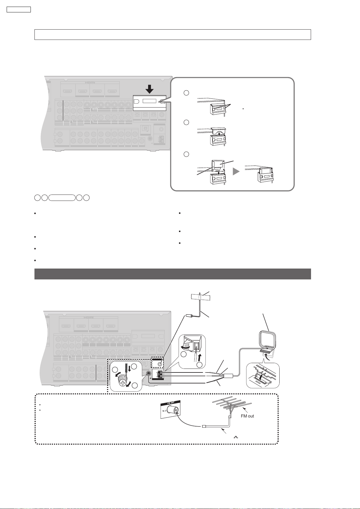
To enjoy wireless audio with SH-FX67
You can connect left and right surround speakers wirelessly by using Panasonic SH-FX67 (a set consisted of a digital transmitter
and a wireless system sold separately) with the unit.
To use these options, insert the digital transmitter into the unit s digital transmitter terminal and connect surround speakers to
SH-FX67’s wireless system. See SH-FX67’s operating instructions for details.
Rear panel
Note
[About MULTI ROOM function]
When the surround speakers are not used wirelessly, you can
use wireless speakers to enjoy music in another room while
enjoying the surround playback with speakers connected to
this unit (MULTI ROOM).
Make sure to set MULTI ROOM in Setting wireless
speakers to enjoy using MULTI ROOM function.
Set SH-FX67 s surround selector to 5.1ch playback mode
when using MULTI ROOM function.
See SH-FX67 s operating instructions for more information.
Ho w to inser
1
Press the dents on both sides with force.
t the digital transmitter
Dents
Use care because the
cover may pop out.
2
Remove the cover
3
Insert fir mly with the label side facing front.
Label
Digital
transmitter
[About 7.1 channel playback]
By using 2 sets of SH-FX67, you can enjoy 7.1 channel
playback, making the surround speakers and surround back
speakers wireless. In that case, make ID number setting
Setting of the surround selector on SH-FX67 is necessary for
7.1 channel playback.
See SH-FX67 s operating instructions for more information.
Connecting antennas
When finished connecting antennas, tune the radio station once and fix the antennas where reception is best
Adhesive tape
AM loop antenna (included)
Rear panel
1
1
2
3
FM outdoor antenna (not included)
Disconnect the FM indoor antenna.
The antenna should be installed by a competent
technician.
FM ANT
Ω
75
20
Keep the antenna cord away from DVD recorders,
Blu-ray Disc/DVD players, and other cords.
FM indoor antenna
(included)
Fix the other end of the
antenna where
reception is best.
White
2
Red
Black
FM outdoor
antenna
75 coaxial cable
SA-BX500PP
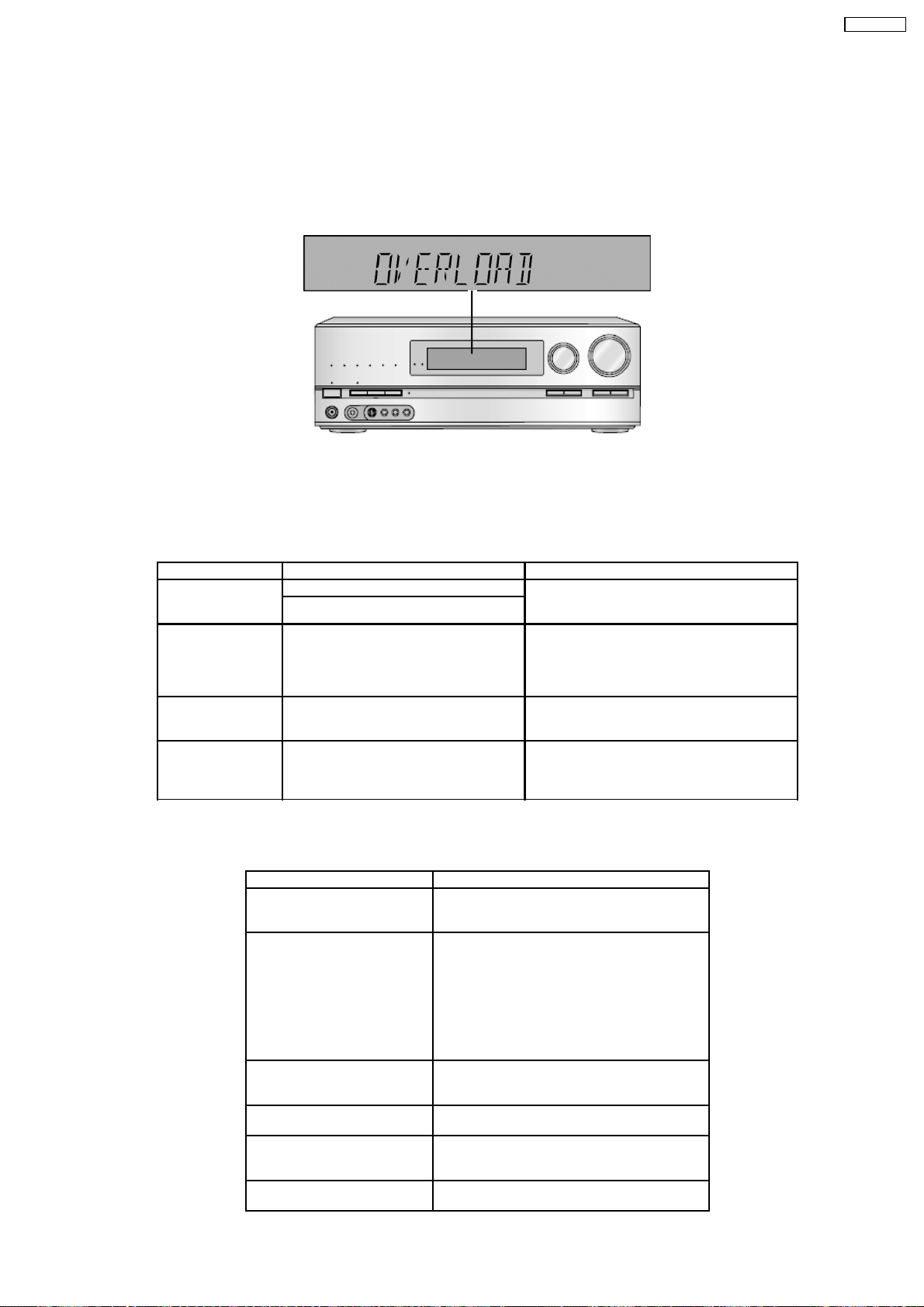
6 Self-Diagnosis and Display Function
This unit is equipped with the self diagnosis display function, which alarms faulty operation with error code. Use this function during
servicing.
6.1. Automatically Displayed Error Codes
An error code automatically appears on the display (FL Display) when faulty operation is detected. Refer to Fig. 6.1.
Fig 6.1
6.2. Display Details
6.2.1. Display Details Table 1
Refer to the following table.
LCD Display Symptom Cause and Remedy
Overload Speaker short, amplifier failure Speaker short and failure in power amplifier, pre-
Temperature protection activated
F61 The abnormalities in an output or power
supply circuit of POWER AMP
F70 Communication error between sub
microprocessor and its peripheral LSI
F76 When the power is turned on, the unit
power automatically turns off; the power
cannot be turned on
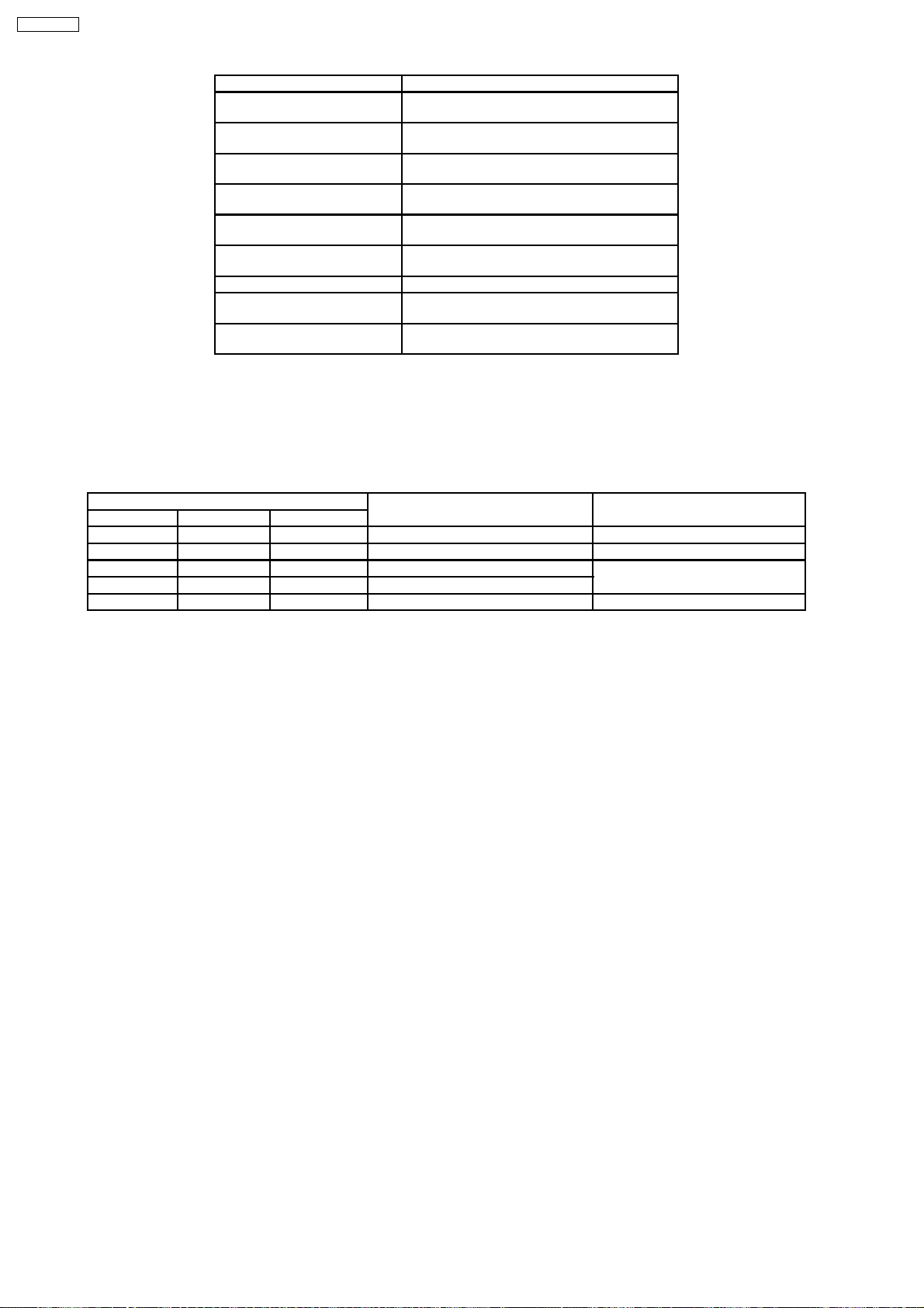
6.2.2. Display Details Table 2
Refer to the following table.
Message Cause/countermeasure
U701 The equipment connected by the HDMI cable is
U703 Should anything unusual happen using an HDMI
U704 The unit has received a signal for a picture format
REMOTE 1 or REMOTE 2 Match the modes on the main unit and the remote
CANCEL MUTING FUNCTION Muting is on.
NO C AND LS/RS SPEAKERS Center and surround speakers are set as absent.
amplifier circuit. Check for faulty parts and
replace with new parts if necessary.
In normal operation, when DCDET2 goes to “L”
(Low) (Not during POWER OFF condition), F61
appears on FLDisplay for 1 second and PCONT
goes to “L” (Low). This is due to speaker output
has DC voltage or fan is not working.
Failure sub microprocessor and its peripherals
LSI. Check for faulty parts and replace with new
parts if necessary.
Failure in the power circuit system of unit. This
may happen when the direct current electricity is
supplied to speaker terminals. Check for the
above and replace with new parts if necessary.
not compatible with the unit’s copyright protection
technology.
connection:
Consult your dealer if the sign remains on the
display after these steps.
OTurn the connected equipment off and on
again.
OPull out the HDMI cable then reinsert it.
OReduce the number of equipment connected in
series to the HDMI terminal if exceeding 2 units.
that is incompatible with the HDMI connection.
Check the settings of the connected equipment.
control.
Press [MUTING] on the remote control to cancel
the function.
Change their setting to present.
21
SA-BX500PP
Message Cause/countermeasure
NO LS/RS SPEAKERS Surround speakers are set as absent. Change
NO LS/RS AND SBL/SBR
SPEAKERS
NO SBL/SBR SPEAKERS Surround back speakers are set as absent.
NOT POSSIBLE FOR ANALOG
8CH INPUT
NOT POSSIBLE FOR THIS
INPUT SOURCE
PCM FIX (flashing) The unit is in the “PCM FIX” mode. Cancel this
SELECT SPEAKER A “SPEAKERS A” is off. Select “SPEAKERS A”.
SPEAKER ARE OFF “SPEAKERS A” and “SPEAKERS B” are off.
NOT SUPPORT FOR THIS
WIRELESS SYSTEM
their setting to present.
Surround and surround back speakers are set as
absent. Change their setting to present.
Change their setting to present.
You are trying to use the effect unavailable for
analogue 8-channel playback.
You are trying to use the effect unavailable for the
current input source.
mode.
Select “SPEAKERS A” or “SPEAKERS B”.
Not compatible with this wireless system.
6.3. Overload/Shutdown Detection internal Condition
It detects OVERLOAD, POWER MALFUNCTION with [THRM_DET], [SHORT_DET] and [DC_DET] input port. It detects the
following condition depending on the input of the port as below table.
(H: DC around 5V / L: DC around 0V)
PROT Detection of malfunction Display and operation
SHORT_DET THRM_DET DC_DET
H L H Normal ---H H H High Temp Refer to ‘THERMAL PROTECTION’
L L H Speaker short Malfunction of Amplifier [OVERLOAD] / POWER OFF
L H H Detection of THERMAL PROTECTION
- - L Detection of POWER MALFUNCTION [_ _ _F76_ _ _] / POWER OFF
6.4. Overload/Thermal Detection Display
When overload is detected, automatic POWER OFF will our. But if any key on the remote control other than the [POWER] key is
pressed before that, the scroll display will show [SWITCH_OFF_POWER]/ Then, 1 second after display of message, [OVERLOAD]
will be shown on the scroll display.
6.5. Activating Self Diagnosis Function (Service Mode)
This mode can be used during servicing.
1. Plug the AC cord to the power source. Press and hold down the [OK] button and the [SPEAKER A] button, and then press the
[POWER] button at the same time.
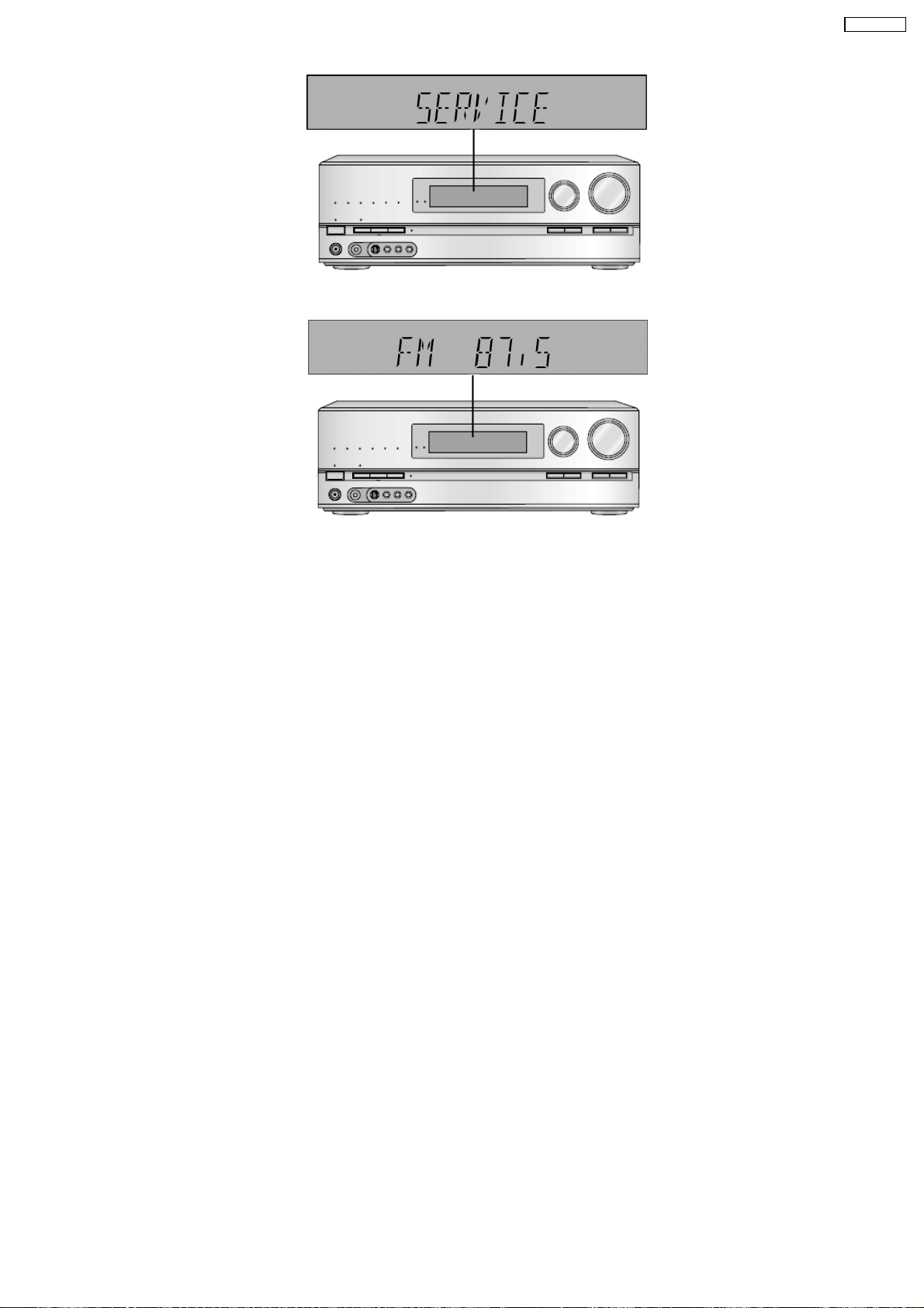
2. The Message, [SERVICE] appears on the display for three seconds, and then it will display the following. Refer to Fig.6.2.
22
SA-BX500PP
Fig 6.2
3. When the [SPEAKER A] button is pressed, the current program filing number [M45_XXXX] appears. The XXXX digit indicates
the ROM checksum used for ROM collection, and if the unit is not loaded with ROM, “NO” appears.
To Confirm the HDMI µP software version: When [SPEAKER B] button is pressed, [H21_XXXX] is displayed.
To confirm the DSP firmware version: When ‘SURROUND’ button is pressed, like ‘D1.02/2.20’ is displayed for 3 seconds.
6.6. Returning to Normal Display
Press the [POWER] button on the unit to exit the function. The power is turned off
6.7. Activating Self Diagnosis Function (Doctor Mode)
This mode can be used during servicing.
1. Plug the AC adapter to the power source. Press and Hold down the [SETUP] button and the [SPEAKER A] button, and then
press the [POWER] button at the same time.
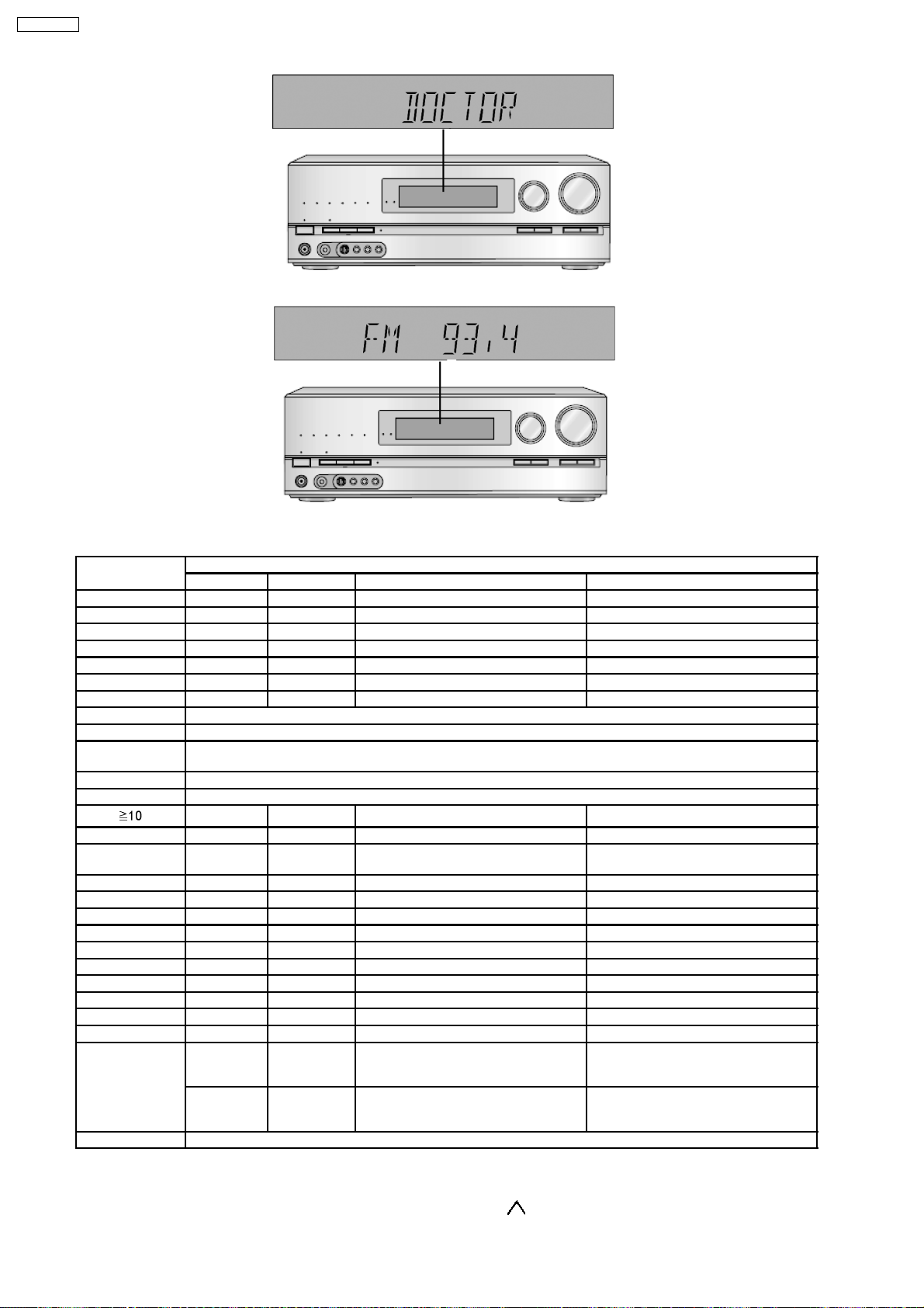
2. Initialize all the setting and set the frequency “93.4MHz” to Tuner.
The message, “_DOCTOR_” appears on the display for three seconds, and then it will display the following. Refer to Fig. 6.3.
23
SA-BX500PP
Fig 6.3
3. Doctor mode function at some remote control codes as below table.
Remote Control Test Mode Function and settings
Selector Surround Other settings Vol/Tone
CH 1 TUNER OFF Frequency: FM min. -48dB/0dB
CH 2 TUNER OFF Frequency: FM max. -48dB/0dB
CH 3 TUNER OFF FM 98.3MHz -18dB/0dB
CH 4 TUNER OFF Frequency: AM min. -48dB/0dB
CH 5 TUNER OFF Frequency: AM max. -48dB/0dB
CH 6 TUNER OFF AM 765kHz (9kHz/step) -18dB/0dB
CH 7 TUNER OFF AM 770kHz (10kHz/step) -18dB/0dB
CH 8 If the input selector is TUNER, auto tuning function is started to upward on current frequency.
CH 9 If the input selector is TUNER, auto tuning function is started to downward on current frequency.
CH 10 All indicators of FL and LED are lit.
CH UP Check Main uP software version.
CH DOWN Sub uP software version and HDMI uP software version are displayed at each time pressing.
MUTING BD P. 8CH ----- -18dB/0dB
INPUT
SELECTOR
PLIIx CD OFF Analog -18dB/0dB
NEO:6 TV OFF Analog -18dB/0dB
SOUND BD/DVD P. OFF Analog -18dB/0dB
DVD R. DVD R. OFF Analog -18dB/0dB
CABLE/SAT CABLE/SAT OFF Analog -18dB/0dB
BD/DVD P. GAME OFF Analog -18dB/0dB
OFF BD/DVD R. OFF Digital (OPT 1) -48dB/0dB
SFC MOVIE BD/DVD P. OFF Digital (OPT 2) -48dB/0dB
TV TV OFF Digital (OPT 3) -48dB/0dB
SFC MUSIC CD OFF Digital (COAX) -48dB/0dB
TEST No change SURROUND If MIC is not inserted, scan the test
DISPLAY If the input selector is TUNER in E2 mode, Display Mode (PS/PTY/RT) is changed
Note: After the setting, only ‘POWER’ button to ‘Checker Command’ code by the remote control can be entered.
BD/DVD P. ----- All CH Output Mode -18dB/0dB
AUX OFF Analog -18dB/0dB
noise out put channel with 500ms
intervals
AUX STEREO If MIC is inserted, mic input is selected
and it is output to speaker in analog
mode
-18dB/0dB
-18dB/0dB
6.8. Wireless Link
When [^^P^^^^^^^] displaying. Power off, Except Pressing Main unit [TUNE ] +Remote control [3] at the same time. All operation
24

is not function. (Volume adjustment or Mute also unfunction)
<FX67 Common frequency fixed method>
Preparation: Beforehand, press remote control [FM/AM], remote control side, will appear FM/AM code stage.
Below is operation of wireless frequency fixed method.
Function Button Condition Display
RF ch1 Fix
(Claim measure)
RF ch2 Fix
(Claim measure)
RF ch3 Fix
(Claim measure)
RF ch AUTO Main unit [TUNE ]
Main unit [TUNE ]
+Remote Control [4] (0xA00413)
Main unit [TUNE ]
+Remote Control [5] (0xA00414)
Main unit [TUNE ]
+Remote Control [6] (0xA00415)
+Remote Control [7] (0xA00416)
When P-ON, Press 5sec
above at the same time.
When P-ON, Press 5sec
above at the same time.
When P-ON, Press 5sec
above at the same time.
When P-ON, Press 5sec
above at the same time.
FL [^RF^^^CH1^] 3sec
event display
FL [^RF^^^CH2^] 3sec
event display
FL [^RF^^^CH3^] 3sec
event display
FL [^RF^^^AUTO^] 3sec
event display
SA-BX500PP
25
SA-BX500PP
7 Assembling and Disassembling
“ATTENTION SERVICER”
Be careful when disassembling and servicing.
Some chassis components may have sharp edges.
Special Note:
1. This section describes the disassembly procedures for all the major printed circuit boards and main components.
2. Before the disassembly process was carried out, do take special note that all safety precautions are to be carried out.
(Ensure that no AC power supply is connected during disassembling.)
3. For assembly after operation checks or replacement, reverse the respective procedures.
Special reassembly procedures are described only when required.
4. Do take note of the locators on each printed circuit board during reassembling procedures.
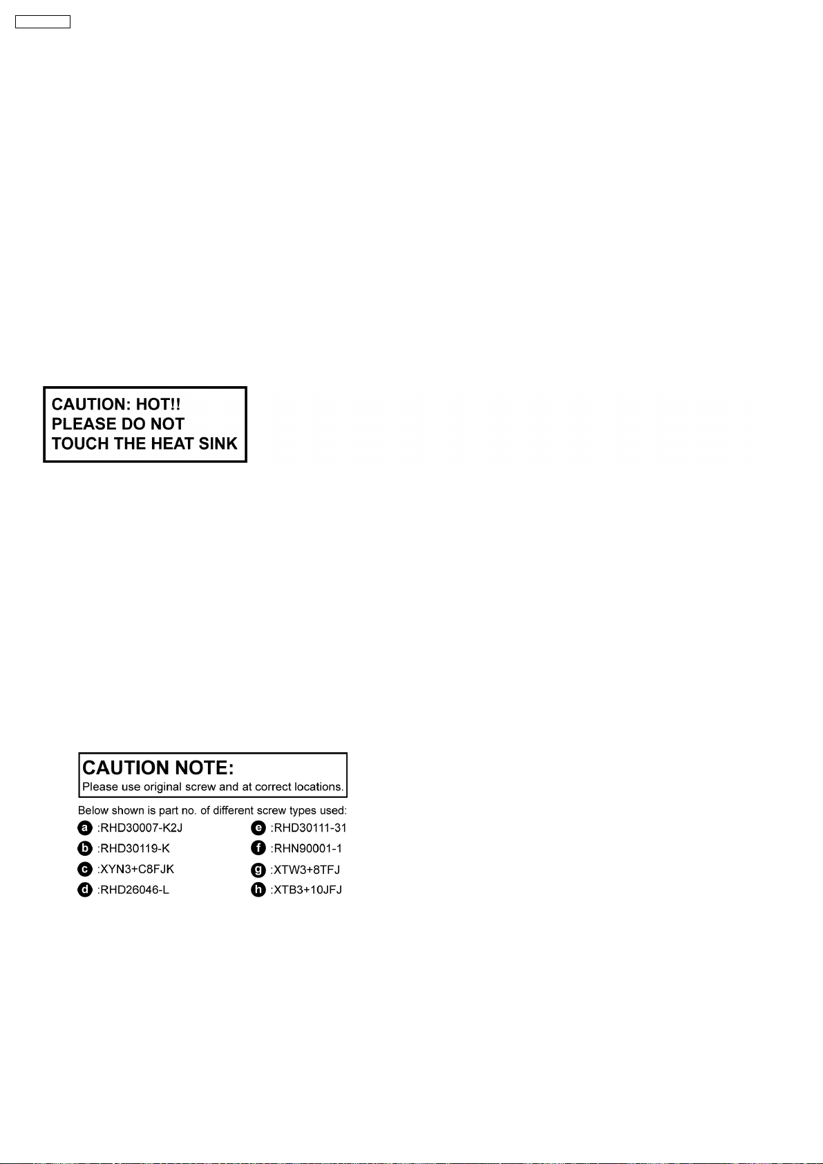
5. The Switch Regulator IC may have high temperature after prolonged use.
6. Use caution when removing the top cabinet and avoid touching heat sinks located in the unit.
7. Select items from the following index when checks or replacement are required.
•
• Disassembly of Top Cabinet
• •
•
• Disassembly and Checking of DSP P.C.B.
• •
•
• Disassembly and Checking of Speaker P.C.B.
• •
•
• Disassembly and Checking of D-Amp B (3CH)/ Fan P.C.B.
• •
•
• Disassembly and Checking of SMPS/ AC Inlet P.C.B.
• •
•
• Disassembly and Checking of D-Amp A (4CH) P.C.B.
• •
•
• Disassembly and Checking of HDMI P.C.B.
• •
•
• Disassembly and Checking of S-Video/ Video P.C.B.
• •
•
• Disassembly and Checking of Wireless Adapter/ Digital/ D-Port P.C.B.
• •
•
• Disassembly and Checking of Main P.C.B.
• •
•
• Disassembly of Front P.C.B.
• •
•
• Disassembly and Checking of Panel/ Headphone/ Volume P.C.B.
• •
26
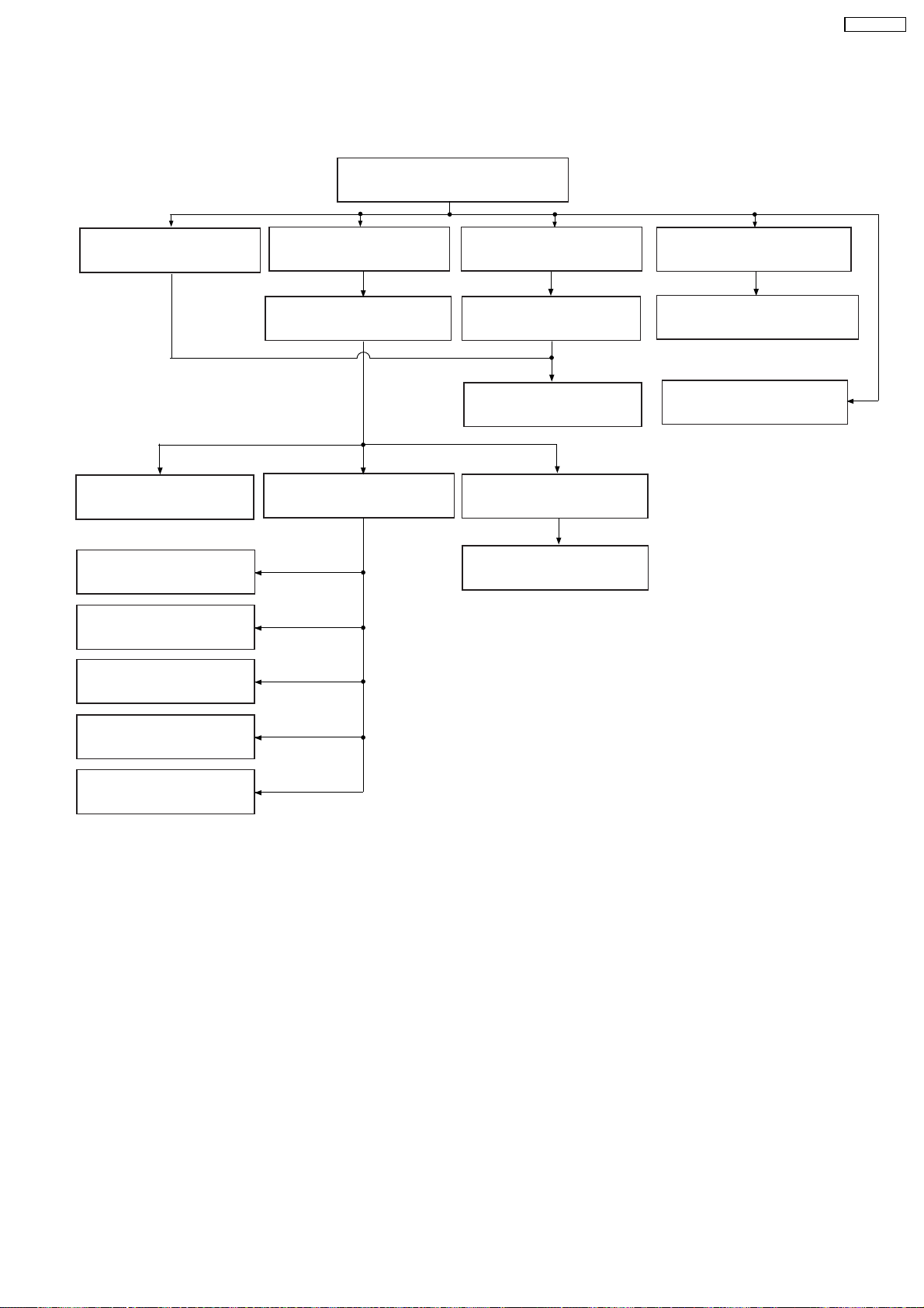
7.1. Disassembly Flow Chart
SA-BX500PP
7.3. Top Cabinet
7.4. DSP (Side A/B)
P.C.B.
7.7. Digital Amp IC
(IC5000)
7.9. Switching Regulator
(IC5701)
7.10. Switch Regulator
(D5702)
7.11. Regulator Diode
(D5801)
7.5. Speaker P.C.B.
7.6. D-Amp B (3CH)
P.C.B.
7.8. SMPS & AC Inlet
P.C.B.
716. HDMI (A/B) P.C.B.
7.17. S-Video & Video
P.C.B.
7.19. Main P.C.B.
7.14. D-Amp A (4CH)
P.C.B.
7.15. Digital Amp IC
(IC5000)
7.20. Front Panel
7.21. Panel, Headphone &
Volume P.C.B.
7.18. Wireless Adapter,
Digital & D-Port
P.C.B.
7.12. Regulator Diode
(D5802)
7.13. Regulator Diode
(D5803)
27
SA-BX500PP
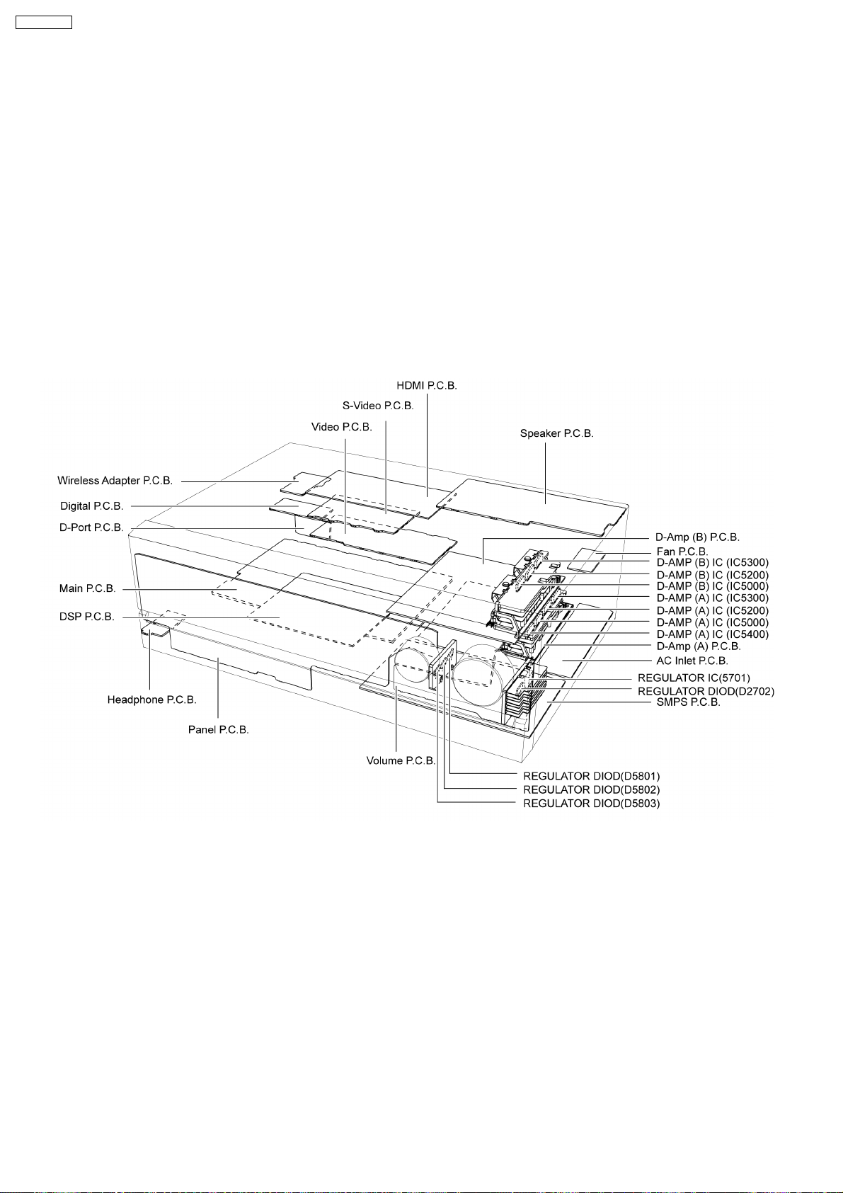
7.2. Main Components and P.C.B. Locations
28
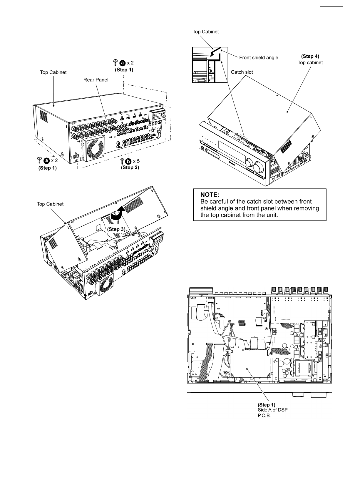
7.3. Disassembly of Top Cabinet
Step 1 Remove 4 screws at the sides of the top cabinet.
Step 2 Remove 5 screws at the rear of the top cabinet.
Step 3 Lift up the top cabinet as arrow shown.
SA-BX500PP
Step 4 Remove the top cabinet.
7.4. Disassembly and checking of
DSP (Side A/B) P.C.B.
•
• Follow (Step 1) to (Step 4) of Item 7.3.
• •
•
• Checking Side A of DSP P.C.B.
• •
Step 1 Proceed to check Side A of DSP P.C.B..
•
• Checking Side B of DSP P.C.B.
• •
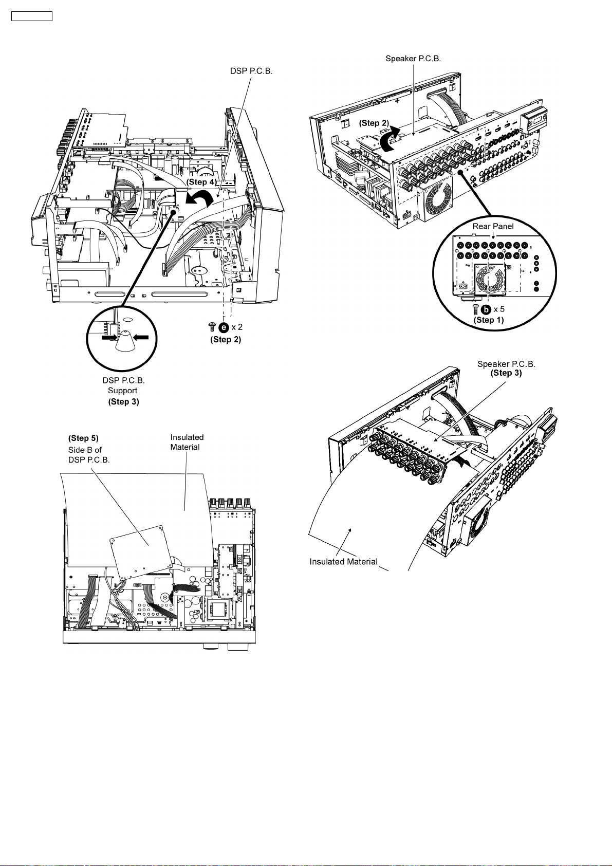
Step 2 Remove 2 screws on DSP P.C.B..
Step 3 Release DSP P.C.B. support on DSP P.C.B..
29
SA-BX500PP
Step 4 Flip the DSP P.C.B. as arrow shown.
Step 5 Proceed to check Side B of DSP P.C.B..
Step 3 Proceed to check the Speaker P.C.B.
Caution: Insulate Speaker P.C.B. from other parts by insulating
material (e.g.: plastic).
7.6. Disassembly and checking of
D-Amp B (3CH) & Fan P.C.B.
Caution: Insulate DSP P.C.B. from other parts by insulating
material (e.g.: plastic).
7.5. Disassembly and checking of
Speaker P.C.B.
•
• Follow (Step 1) to (Step 4) of Item 7.3.
• •
Step 1 Remove 5 screws at rear panel.
Step 2 Move the Speaker P.C.B. as arrow shown.
•
• Follow (Step 1) to (Step 4) of Item 7.3.
• •
•
• Follow (Step 1) to (Step 3) of Item 7.5.
• •
Step 1 Detach 12P cable at the connector (JW4602) on
Speaker P.C.B..
Step 2 Detach 9P cable at the connector (JW4603) on Speaker
P.C.B..
Step 3 Flip Speaker P.C.B. as arrow shown
30
 Loading...