

Operating Instructions
AV Control Receiver
Model No. SA-BX500
Dear customer
Thank you for purchasing this product.
Before connecting, operating or adjusting this product, please read the
instructions completely.
Please keep this manual for future reference.
Note
“EB” on the packaging indicates the United Kingdom.
EB EG GN
RQT9224-1B
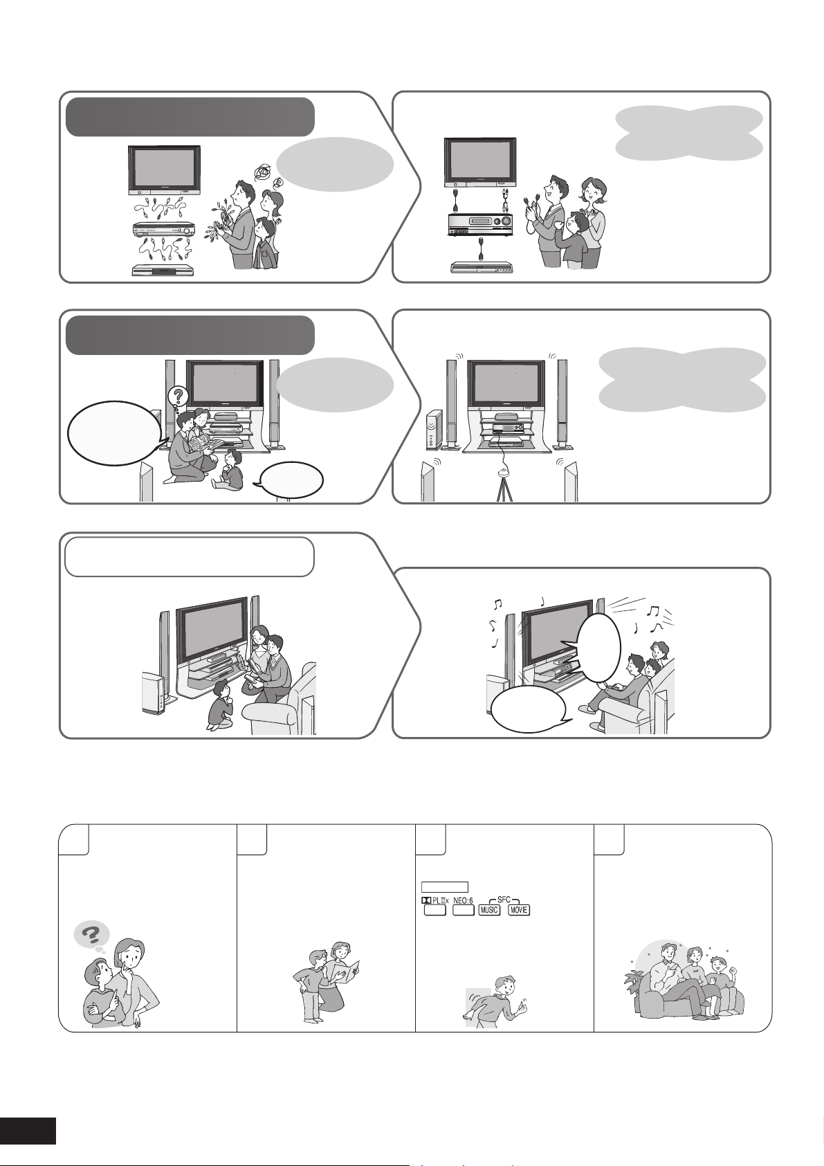
Enjoying the Home Theater has become easy!
With SA-BX500!
With SA-BX500!
Until no
...
Until no
...
With SA-BX500!
Connections
Until no
Until now...
w...
Settings
Until no
Until now...
We must
make speaker
settings...
w...
Many different
cables were
necessary.
Manual setting for
each speaker.
With SA-BX500!
With SA-BX500!
With SA-BX500!
AB
Simple connections
using 2 HDMI cables and
1 stereo phono cable!
Other connections are also
∗
possible.
Automatic speaker setup
leads you to the easiest
way of speakers setting
(
➔ pages 24, 25).
It’s
difficult.
When you connect the unit to your TV (VIERA) and DVD
recorder (DIGA) compatible with VIERA Link
Press just one button and enjoy the Home Theater (➔ pages 32, 33).
The
Home
Theater
begins.
One-touch
playback.
VIERA Link
Previous Home Theater systems required multiple
operations.
Enjoy the full surround sound from all speakers connected!!
1
How can we enjoy
TV with surround
sound?
Connections
and settings
are all
complete.
2 3 4
TV outputs 2-channel
stereo sounds and
only front speakers can
make audio output.
remote control
to enjoy surround sound
(➔ pages 28, 29).
Just press
SURROUND
on the unit
on the
Great!! We can enjoy
TV with surround
sound.
2
RQT9224
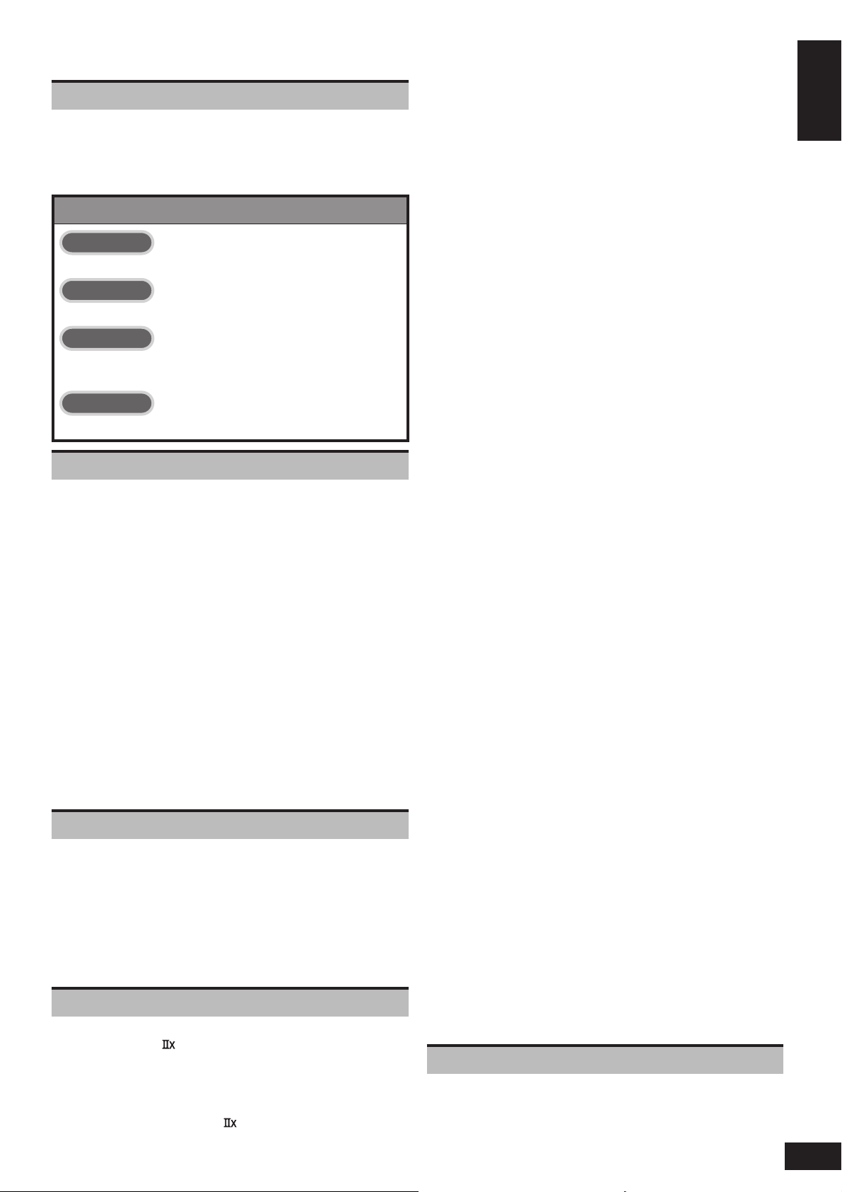
Table of contents
Before use
Enjoying the Home Theater has become easy! ................ 2
Caution for AC Mains Lead ................................................ 4
Safety precautions .............................................................5
Supplied accessories ......................................................... 6
Control guide ...................................................................... 6
Quick guide
Step 1
Placing speakers .............................................. 9
Step 2
Connecting speakers ..................................... 10
Step 3
Connecting a TV and a
Blu-ray Disc/DVD player ................................. 12
Step 4
Watching TV or DVD ........................................ 14
Preparations
Connections ....................................................... 16
Basic connections ............................................................ 16
Connecting cables to video and audio terminals
(Connecting equipment without HDMI terminal) ............... 16
Connecting equipment with HDMI terminal ...................... 17
Connecting cables to S video and audio terminals ....... 18
Connecting cables to component and
audio terminals ................................................................. 19
Other connections ............................................................ 20
To enjoy analogue sounds ................................................ 20
To enjoy high-quality analogue sounds
(Analogue 8-channel connections) ................................... 20
To connect the unit to a CD player. .................................... 20
To connect the unit for audio or picture recording ............. 21
To connect the unit to a video camera etc. ........................ 21
Connecting other speakers .............................................22
To connect bi-wire speakers ............................................. 22
To connect a second pair of front speakers (SPEAKERS B)
To enjoy wireless audio with SH-FX67 .............................. 23
Connecting antennas ....................................................... 23
Auto speaker setup using the setup microphone
.... 22
... 24
Basic operations
Enjoying the Home Theater ...............................26
Basic playback ................................................................. 26
Using surround speakers wirelessly with SH-FX67 ....... 27
To enjoy 7.1 channel playback using 2 sets of SH-FX67 ... 27
When you use wireless speakers in another room (MULTI ROOM)
Using SPEAKERS B .........................................................27
Playback when making analogue 8-channel connections
Enjoying only with TV speaker ........................................ 27
Enjoying 7.1-channel virtual surround playback ........... 27
.... 27
...... 27
Operations
Listening to surround sound ................................... 28
Dolby Pro Logic
NEO:6 ................................................................................ 28
SFC (Sound Field Control) ............................................... 28
Sound fi eld ....................................................................... 29
Remote controlling sound effects .................... 30
Adjusting Dolby Pro Logic ’s “ MUSIC ” mode .............30
Adjusting NEO:6’s “MUSIC ” mode ................................. 30
Convenient functions ........................................ 31
Adjusting speaker volumes ............................................. 31
........................................................... 28
Silencing speakers temporarily ...................................... 31
Displaying the current status ..........................................31
Using the VIERA Link “HDAVI ControlTM” ......... 32
Enjoying the Home Theater through one-touch operations
.... 33
Using the sound menu ...................................... 34
Adjusting the speaker level .............................................34
Adjusting the bass ........................................................... 34
Adjusting the treble .......................................................... 34
Balancing front speaker volume .....................................35
Changing the audio output (Dual programme) .............. 35
Listening clearly at low volume ....................................... 35
Using whisper mode surround ........................................ 35
Using the setup menu ........................................ 36
Basic operation ................................................................ 36
Adjusting the brightness of the display .......................... 37
Using sleep timer .............................................................. 37
Setting speakers and their sizes .....................................37
Setting distances .............................................................. 37
Setting the lowpass fi lter ................................................. 38
Changing auto speaker settings .................................... 38
To return speakers to factory settings ............................... 38
Setting the unit against automatic polarity adjustment ...... 38
Adjusting the high-frequency sound quality of the set frequency response
Making bi-wire setting ...................................................... 38
Setting the speaker impedance ....................................... 38
Changing the input settings ............................................ 39
Setting the placement positions for surround speakers
Setting wireless speakers ................................................ 39
Setting input signals ........................................................39
Adjusting input levels for external terminals ................. 39
Reducing standby power consumption (power save mode)
Setting VIERA Link to “OFF ” ........................................... 40
Switching the attenuator .................................................. 40
Adjusting the time lag by delaying audio
output when pictures on TV arrives after sounds .......... 40
Changing the volume display .......................................... 40
Reset (factory settings) ................................................... 40
... 38
.... 39
..... 40
Using headphones ............................................. 41
Recording ........................................................... 41
Remote controlling a TV or DVD recorder etc
Remote controlling a TV, cable box and satellite receiver
Using two or more Panasonic equipment
(a mini component system, an AV amp etc.) ................... 42
Remote controlling a DVD recorder ................................ 43
Remote controlling a Blu-ray Disc/DVD player ............... 44
Entering a code to operate other equipment .................. 45
. .... 42
... 42
Enjoying the Radio ............................................ 46
Preset tuning .................................................................... 46
Auto presetting ................................................................. 46
Manual presetting ............................................................ 46
Listening to preset stations (using the remote control) ..... 46
Manual tuning ................................................................... 47
Tuning directly using the numbered buttons ..................... 47
Using the unit ................................................................... 47
Using the remote control .................................................. 47
Reducing excessive noise ............................................... 47
AM allocation .................................................................... 47
RDS broadcasts ................................................................ 48
Changing the display ........................................................ 48
PTY displays ....................................................................48
Playing an iPod on this unit ...............................49
Playing a music recorded on iPod ................................... 49
Reference
Other information .............................................. 50
Glossary ............................................................. 52
Specifi cations .................................................... 53
Error messages .................................................. 53
Troubleshooting guide ......................................54
Maintenance ....................................................... 55
3
RQT9224
Before use
Enjoying the Home Theater has become easy!/Table of contents
Caution for AC Mains Lead
(For the United Kingdom and Republic of Ireland)
(“EB” area code model only)
For your safety, please read the following text
carefully.
This appliance is supplied with a moulded three pin
mains plug for your safety and convenience.
A 5-ampere fuse is fi tted in this plug.
Should the fuse need to be replaced please ensure
that the replacement fuse has a rating of 5-ampere
and that it is approved by ASTA or BSI to BS1362.
Check for the ASTA mark or the BSI mark
on the body of the fuse.
If the plug contains a removable fuse cover you
must ensure that it is refi tted when the fuse is
replaced.
If you lose the fuse cover the plug must not be used
until a replacement cover is obtained.
A replacement fuse cover can be purchased from
your local dealer.
WARNING: DO NOT CONNECT EITHER WIRE
TO THE EARTH TERMINAL WHICH IS MARKED
WITH THE LETTER E, BY THE EARTH SYMBOL
OR COLOURED GREEN OR GREEN/
YELLOW.
THIS PLUG IS NOT WATERPROOF—KEEP DRY.
Before use
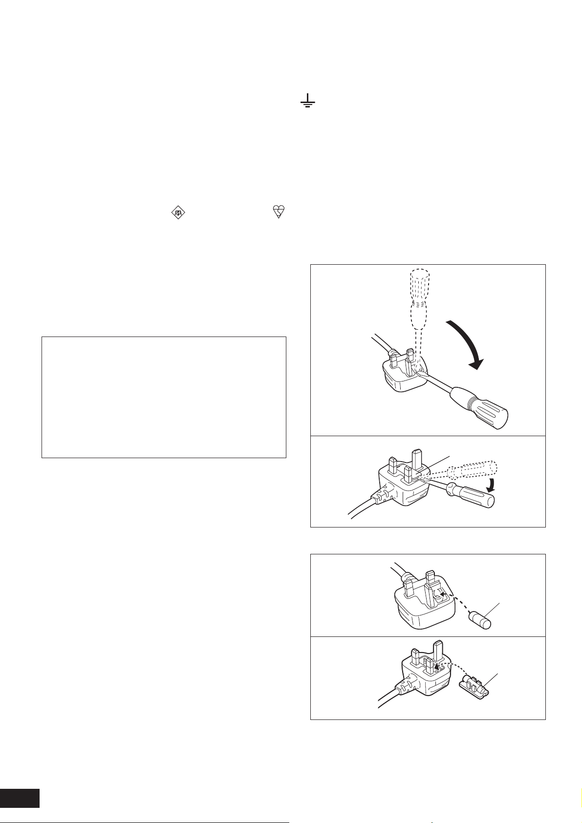
Remove the connector cover.
How to replace the fuse
The location of the fuse differ according to the type
of AC mains plug (fi gures A and B). Confi rm the AC
mains plug fi tted and follow the instructions below.
Illustrations may differ from actual AC mains plug.
1. Open the fuse cover with a screwdriver.
Figure A
CAUTION!
IF THE FITTED MOULDED PLUG IS
UNSUITABLE FOR THE SOCKET OUTLET IN
YOUR HOME THEN THE FUSE SHOULD BE
REMOVED AND THE PLUG CUT OFF AND
DISPOSED OF SAFELY.
THERE IS A DANGER OF SEVERE
ELECTRICAL SHOCK IF THE CUT OFF PLUG IS
INSERTED INTO ANY 13-AMPERE SOCKET.
If a new plug is to be fi tted please observe the
wiring code as stated below.
If in any doubt please consult a qualifi ed electrician.
IMPORTANT
The wires in this mains lead are coloured in
accordance with the following code:
Blue: Neutral, Brown: Live.
As these colours may not correspond with the
coloured markings identifying the terminals in your
plug, proceed as follows:
The wire which is coloured Blue must be connected
to the terminal which is marked with the letter N or
coloured Black or Blue.
The wire which is coloured Brown must be
connected to the terminal which is marked with the
letter L or coloured Brown or Red.
Figure B
2. Replace the fuse and close or attach the fuse cover.
Figure A
Figure B
Fuse cover
Fuse
(5 ampere)
Fuse
(5 ampere)
4
RQT9224

Safety precautions
Placement
Set the unit up on an even surface away from direct
sunlight, high temperatures, high humidity, and
excessive vibration. These conditions can damage
the cabinet and other components, thereby
shortening the unit’s service life.
Do not place heavy items on the unit.
Voltage
Do not use high voltage power sources. This can
overload the unit and cause a fi re.
Do not use a DC power source. Check the source
carefully when setting the unit up on a ship or other
place where DC is used.
AC mains lead protection
Ensure the AC mains lead is connected correctly
and not damaged. Poor connection and lead
damage can cause fi re or electric shock. Do not
pull, bend, or place heavy items on the lead.
Grasp the plug fi rmly when unplugging the lead.
Pulling the AC mains lead can cause electric shock.
Do not handle the plug with wet hands. This can
cause electric shock.
Foreign matter
Do not let metal objects fall inside the unit. This can
cause electric shock or malfunction.
Do not let liquids get into the unit. This can cause
electric shock or malfunction. If this occurs,
immediately disconnect the unit from the AC mains
supply and contact your dealer.
Do not spray insecticides onto or into the unit.
They contain fl ammable gases which can ignite if
sprayed into the unit.
Service
Do not attempt to repair this unit by yourself. If
sound is interrupted, indicators fail to light, smoke
appears, or any other problem that is not covered in
these instructions occurs, disconnect the AC mains
lead and contact your dealer or an authorised
service centre. Electric shock or damage to the unit
can occur if the unit is repaired, disassembled or
reconstructed by unqualifi ed persons.
Extend operating life by disconnecting the unit from
the AC mains if it is not to be used for a long time.
Before use
Caution for AC Mains Lead/Safety precautions
5
RQT9224
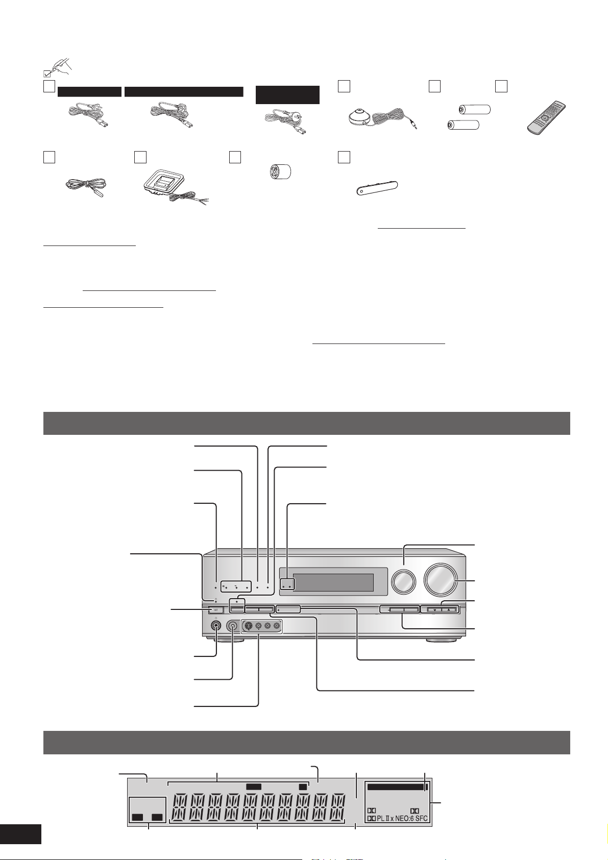
Supplied accessories
Please check and identify the supplied accessories.
1 AC mains lead
For continental Europe
(K2CQ2CA00007) (K2CT3CA00004)
1 FM indoor antenna
(RSA0007-M)
Sales and Support Information
For the United Kingdom and Republic of Ireland
1 AM loop antenna
(N1DAAAA00002)
For Australia and
New Zealand
(K2CJ2DA00010)
1 Antenna plug adapter
For the United Kingdom
and Republic of Ireland
(K1YZ02000013)
(For the United Kingdom and Republic of Ireland)
Customer Care Centre
•
For customers within the UK: 0844 844 3852
•
For customers within the Republic of Ireland: 01 289 8333
•
Visit our website for product information
•
E-mail: customer.care@panasonic.co.uk
Direct Sales at Panasonic UK
•
For customers: 0844 844 3856
•
Order accessory and consumable items for your product with
ease and confi dence by phoning our Customer Care Centre
Monday-Thursday 9:00am-5:30pm, Friday 9:30am-5:30pm
(Excluding public holidays).
•
Or go on line through our Internet Accessory ordering
application at www.panasonic.co.uk.
•
Most major credit and debit cards accepted.
•
All enquiries transactions and distribution facilities are
provided directly by Panasonic UK Ltd.
•
It couldn’t be simpler!
•
Also available through our Internet is direct shopping for
a wide range of fi nished products, take a browse on our
website for further details.
Interested in purchasing an extended guarantee?
Please call 0870 240 6284 or visit our website
www.panasonic.co.uk/guarantee.
1 Setup microphone
(L0CBAB000128)
1 Front terminal
cover
(RGK2137-K)
2 Batteries 1 Remote control
(N2QAKB000070)
Use numbers indicated in parentheses
when asking for replacement parts.
(Product numbers correct as of May
2008. These may be subject to change.)
Control guide
This unit
Lights on when playing a disc using
multi-channel LPCM format
Lights on when playing a disc using
high defi nition audio format such as
Blu-ray Disc
Lights on when the following multichannel playback settings are used
• When playing multi-channel sources
• When using surround effects for two-
channel sources, etc.
Standby indicator [^]
When the unit is connected to the AC
mains supply, this indicator lights up in
standby mode and goes out when the
unit is turned on.
Standby/on switch [8]
Press to switch the unit from on to
standby mode or vice versa. In standby
mode, the unit is still consuming a small
amount of power.
For connecting headphones (➔ page
41)
For connecting the setup microphone
(➔ page 24)
For connecting a video camera etc.
(➔ page 21)
PROCESSING
MULTI CH
TrueHD
D+
DTS-HD
SURROUND
SPEAKERS A
SETUP MIC
S VIDEO
Lights on when BI-AMP is on (➔ page 51)
For switching the surround playback on
and off (The indicator lights up when the
surround playback is on.) (➔ page 29)
Lights up under the condition that using the
digital transmitter (SH-FX67) is possible
For selecting input
INPUT SELECTOR
WIRELESS READY
MULTI CH
SURROUND M.ROOM
BI-AMP
LPCM
SPEAKERS B
AUX
VIDEO
AUTO SPEAKER SETUP
L - AUDIO - R
-
SETUP
RETURN
VOLUME
_
OK
TUNE
sources (➔ pages 15,
26 and 41)
For adjusting volumes
(➔ pages 15, 26 and
41)
+
For tuning the radio
(➔ page 47)
For SETUP operations
(➔ page 36)
Lights on during the
auto speaker setup
(➔ page 24)
For selecting front
speakers (➔ pages 24,
26 and 27)
6
RQT9224
Display
Lights on when
2-channel mix is
functioning
(➔ pages 27, 41
and 51)
(➔ pages 15, 24, 26 and 27)
2CH MIX
SPEAKERS
BI-WIRE
A B
Radio display
TUNED
MONO ST
Lights on when sleep
timer is set (➔ page 37)
RDS
PS
PTY
M
SLEEP
Unit display
m
kHz
MHz
Frequency unit indicatorsGeneral displayDisplays front speakers in use
Lights on when PCM FIX is selected (➔ page 39)
DIGITAL INPUT
DTS 96/24DTS
DIGITAL EX
-ES
PCM
Lights on when the
corresponding digital
EX
source is input (➔ page 50)
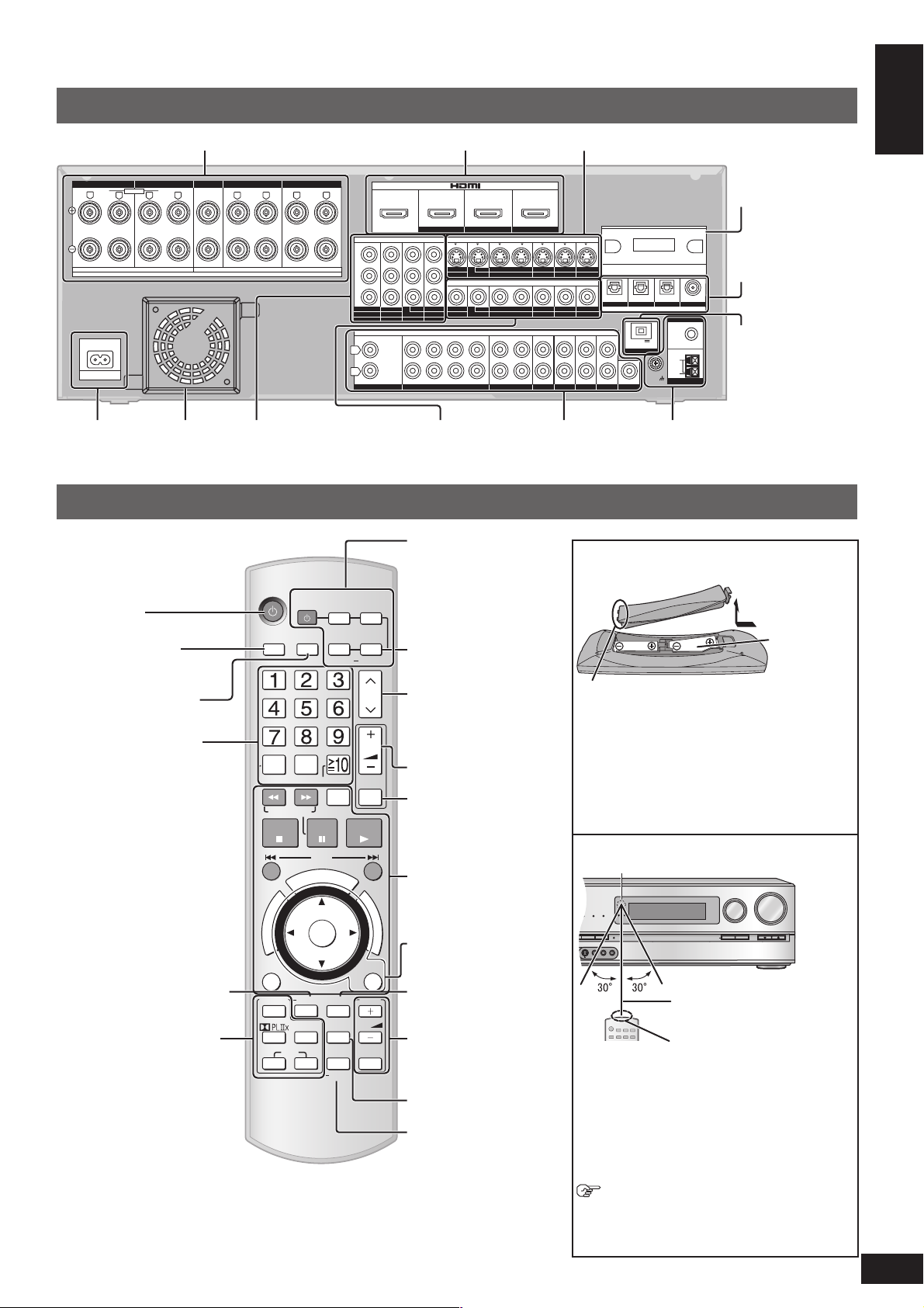
Rear Panel
O
O
U
C
H
P
L
A
Y
WIRELESS READY
SURROUND M.ROOM
INPUT SELECTOR
VOLUME
+
_
DTS-HD
MULTI CH
LPCM
BI-AMP
AUX
TUNE
RETURN
AUTO SPEAKER SETUP
-
SETUP
OK
SPEAKERS A
SPEAKERS B
S VIDEO
VIDEO
L - AUDIO - R
Speaker terminal (➔ pages 10, 11 and 22)
FRONT A
FRONT A FRONT B CENTER
LF HF
BI-WIRE
R
L
A OR B / BI-WIRE (4-16 Ω EACH SPEAKER) A AND B (6-16 Ω EACH SPEAKER)
A
C IN~
AC inlet
(➔ pages 12
R
Exhaust hole
(Cooling fan)
FRONT B
CENTER
SURROUND SURROUND BACK
SPEAKERS
SURROUND
(6-16 Ω EACH SPEAKER)
L
Component terminal
(➔ page 19)
and 13)
SURROUND BACK
L L
RR
HDMI terminal (➔ pages 13, 17 and 32)
IN IN
(DVD RECORDER)
COMPONENT VIDEO
IN
DVD PLAYER)
(CABLE/SAT)
CENTER
SUBWOOFER
BD/DVD PLAYER / ANALOG 8CH IN DVD RECORDER
HDMI 1
OUT OUT
TV MONITOR
OUT
IN
TV MONITOR
SURROUND BACK
SURROUND
(BD/DVD PLAYER)
HDMI 2 HDMI 3
IN
BD/
DVD RECORDER
DVD PLAYER
IN
OUT
BD/(BD/
DVD PLAYER
DVD RECORDER
AUDIO
FRONT
OUT
Video terminal
(➔ pages 12, 16
and 21)
IN
(CABLE/SAT)
S VIDEO
IN IN IN IN
VCR
VIDEO
IN IN IN
VCR
IN IN
IN IN IN
VCR
Audio terminal
(➔ pages 11, 12, 13,
16 and 18 to 21)
Y
B
P
R
P
OUT
TV MONITOR
L
R
IN
CD
OUT
IN
(DVD RECORDER)
123
S video terminal (➔ pages 18 and 21)
Digital transmitter
terminal
(➔ page 23)
Digital input terminal
(➔ pages 16, 18, 19,
CABLE/SAT
CABLE/SAT
CABLE/SAT
GAME
GAME
GAME
IN
(BD/DVD PLAYER)
(DVD RECORDER)
OPTICAL 2 OPTICAL 3 COAXIAL
OPTICAL 1
DC OUT 5V
500mA MAX
OPTION V 1
OUT
TV
SUBWOOFER
DIGITAL IN
LOOP ANT
GND
(TV)
FM ANT
75
Ω
LOOP
EXT
AM ANT
20 and 32)
(CD)
Option port terminal
(➔ page 49)
Antenna terminal
(➔ page 23)
Before use
Remote control
Supplied accessories/Control guide
7
RQT9224
Power button
For selecting input
sources (➔ pages
26 and 41)
For switching FM or AM
(➔ pages 46 and 47)
For inputting channels
TV, cable box and satellite
receiver (➔ page 42)
DVD recorder
(➔ page 43)
Radio (➔ page 46)
For selecting a track or
chapter
DVD recorder (➔ page 43)
Blu-ray Disc/DVD player
(➔ page 44)
For inputting frequencies
(➔ page 47)
For confi rming speaker
output (➔ page 14)/For auto
speaker setup (➔ pages
24 and 25)/For adjusting
speaker level (➔ page 31)
For listening to surround
sounds (➔ pages 28 to 30)
INPUT
SELECTOR
DIRECT
TUNING
DISC
SEARCH/SLOW
STOP
U
N
E
R
M
O
T
P
A
O
G
I
T
V
A
N
T
C
E
R
I
D
OPTION
SURROUND
OFF
SFC
MUSIC MOVIE
AV
SYSTEM
FM/AM
0
-/--
PAUSE
SKIP
U
O
T
E
N
O
OK
AUTO
TEST
NEO : 6
TV
CABLE
SAT
DRIVE
SELECT
C
H
P
L
SOUND
MENU
DISPLAY
OPTION
PORT
SETUP
RECORDER
DVD
PLAYER
BD/DVD
ANALOG 8CH
CH
VOL
MUTING
PLAY
A
Y
F
U
N
C
T
I
O
N
S
RETURN
TV
VOL
TV/AV
For switching an input
source on and off/
Source switching/
Switching remote control
modes (➔ pages 42 to 45)
For playing 8 channels
sources (➔ page 27)
For selecting a channel
TV, cable box and satellite
receiver (➔ page 42)
DVD recorder (➔ page 43
Radio (➔ page 46)
For adjusting volumes
(➔ pages 14, 15, 26 and
41)
For silencing speakers
temporarily (➔ page 31)
For operating other
equipment
(➔ pages 33 and 42 to 44)
For operating SOUND
MENU (➔ pages 34 and
35)/SETUP (➔ page 36)
For selecting SOUND
MENU (➔ pages 34 and
35)
For operating a TV
(➔ page 42)
For changing the display
(➔ pages 31 and 48)
For playing an iPod (➔
page 49)/For entering
SETUP menu items
(➔ page 36)
Batteries
Press on the tab to open.
(R6/LR6, AA)
Place this side in before the other side
when you close.
)
• Insert so the poles (( and )) match those in the
remote control.
• Do not use rechargeable type batteries.
• Do not heat or expose to fl ame.
• Do not leave the batteries in an automobile
exposed to direct sunlight for a long period of
time with doors and windows closed.
Use
Remote control signal sensor
About 7 meters or less when you
sit directly in front of the signal
sensor (Exact distance depends
on angles).
Transmission window
Caution
• Do not place an object between the signal
sensor and the remote control.
• Do not place the signal sensor under direct
sunlight or the strong light of an inverter
fl uorescent lamp.
• Keep the transmission window and the unit’s
sensor free from dust.
When you set the unit in a cabinet
The remote controlling range may decrease
depending on the thickness or colours of
glass cabinet doors.
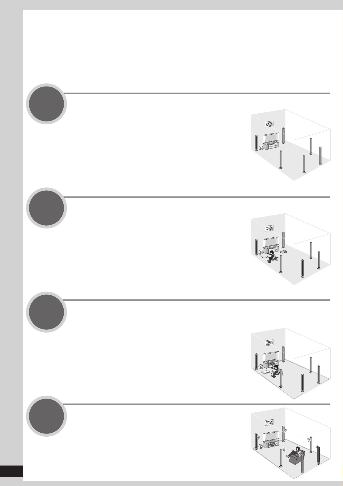
Quick guide
This section guides you through the easiest and simplest way to setup the Home Theater.
Refer to the steps indicated below. The steps 1 to 4 indicate the method one by one from when you purchase
the unit until you can enjoy the Home Theater.
• Turn off all equipment before making any connections.
• Peripheral equipment sold separately unless otherwise indicated.
• To connect equipment, refer to the appropriate operating instructions.
Step
1
Step
2
Placing speakers
You can enjoy the best quality of sounds by
setting speakers properly.
Connecting speakers
You can install and connect speakers in 7.1ch
setting.
(➔ page 9)
(➔ pages 10 to 11)
8
RQT9224
Step
3
Step
4
Connecting a TV and a Blu-ray Disc/DVD player
(➔ pages 12 to 13)
You can easily enjoy high-quality pictures and
sounds.
Watching TV or DVD
You can enjoy TV and DVD with surround
sound.
(➔ pages 14 to 15)
〜♪
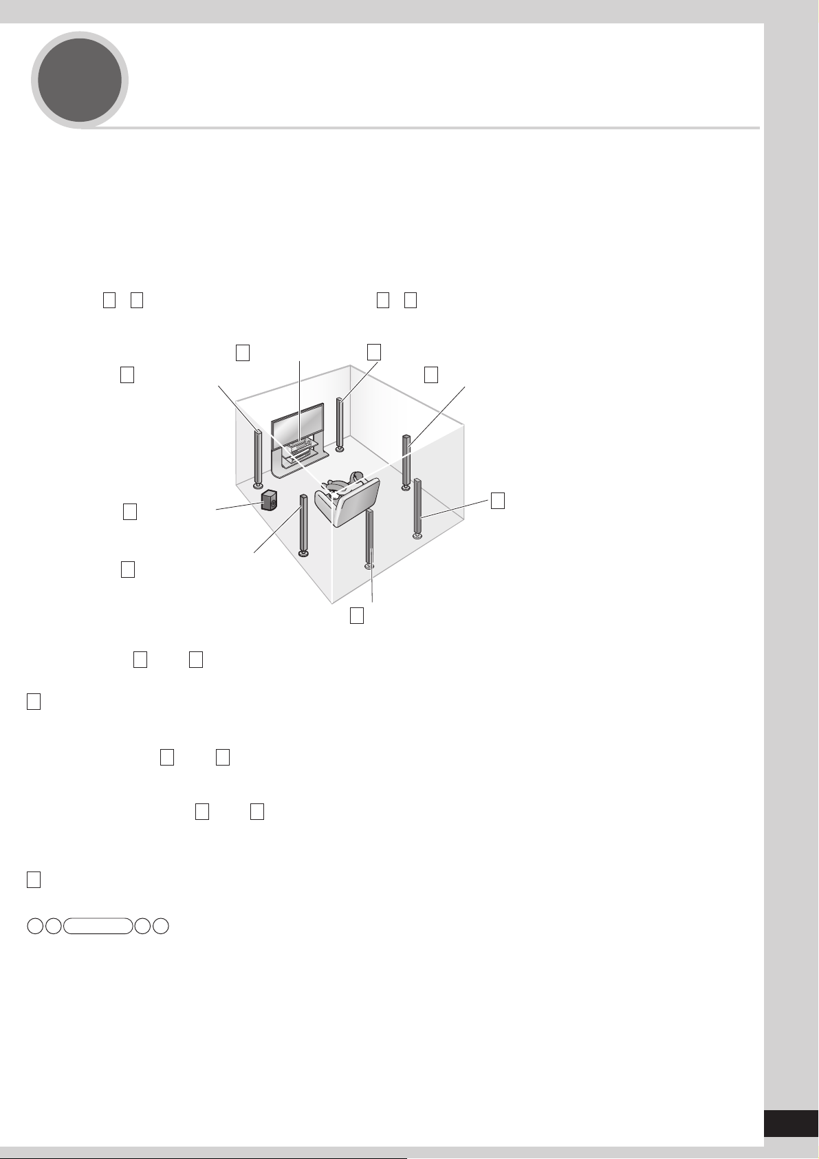
Step
1
5.1, 6.1, 7.1 etc. channel playback is possible on this unit. This page introduces speaker settings for 7.1 channel
playback.
The ideal placement is to set each speaker (excluding the subwoofer) the same distance away from the listening-viewing
position.
Measure the actual distance from each of the connected speakers to the listening-viewing position and perform steps
instructed in “Setting distances” (➔ page 37) or perform steps instructed in “Auto speaker setup using the setup
microphone” (➔ pages 24 and 25) when you cannot install speakers the same distance away.
Example: Front speakers (2), center speaker (1), surround speakers (2), surround back speakers (2) and
Placing speakers
subwoofer (1)
A
– H in the illustration below correspond to A – H in “Connecting speakers” (➔ pages 10 and 11).
Front speaker (right)
A
Surround speaker (right)
D
Front speaker (left)
B
Center speaker
C
Quick guide
Placing speakers
F
Active
H
subwoofer
Surround speaker (left)
E
Surround back speaker (left)
G
Front speakers (A right, B left)
Place on the left and right of the TV at seated ear height so that there is good coherency between the picture and sound.
C Center speaker
Place underneath or above the center of the TV.
When you do not install the center speaker, sound assigned to it is distributed to front speakers and output from them.
Surround speakers (D right, E left)
Place on the side of or slightly behind the listening-viewing position.
When you do not install surround speakers, sound assigned to them is distributed to front speakers and output from them.
Surround back speakers (F right, G left)
Place behind the listening-viewing position, about 1 meter higher than ear level.
When you do not install any surround back speaker, sound assigned to them is distributed to surround speakers or front speakers
and output from them.
H Active subwoofer
The active subwoofer can be placed in any position as long as it is at a reasonable distance from the TV.
Surround back speaker
(right)
Note
• Aim front faces of all speakers at the listening-viewing position for setting.
9
RQT9224
Step
B
O
/
D
E
2
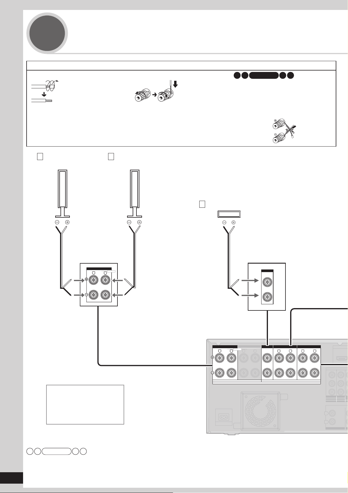
Connecting speakers
1
Remove the vinyl covering the tips of
speaker cables by twisting it off.
Front speaker (right)
A
How to connect speaker cables
2
Speaker terminals
Front speaker (left)
B
Center speaker
C
Note
• Connect speaker cables properly to
terminals after making sure left and right,
and ( and ). Improper connections may
cause the unit to develop problems.
• Do not short-circuit speaker cables. The
action may damage circuits.
10
RQT9224
FRONT A
R
FRONT A
BI-WIRE
LF
L
CENTER
CENTER
Rear panel
FRONT A
FRONT A CENTER
LF HF
R
A OR B / BI-WIRE (4-16 Ω EACH SPEAKER) A AND B (6-16 Ω EACH SPEAKER)
FRONT B
FRONT B
BI-WIRE
L
R
Speaker impedance
Front A: 4 to 16
Center: 6 to 16
Surround: 6 to 16
Surround back: 6 to 16
Ω
Ω
Ω
Ω
A
C IN~
Note
• Do not forget to take steps instructed in “Auto speaker setup using the setup microphone” (➔ pages 24 and 25) after connecting a
new speaker.
• When connecting speakers with the impedance of 4 Ω, make sure to set “4 OHMS ” in “Setting the speaker impedance” on page 38.
CENTER
SURROUND SURROUND BACK
SPEAKERS
SURROUND
(6-16 Ω EACH SPEAKER)
L
SURROUND BACK
L L
RR
Y
B
P
R
P
OUT
TV MONITOR
L
R
IN
CD
OUT
C
IN
(BD
(DVD RECORDER)
DV
1
C
SU
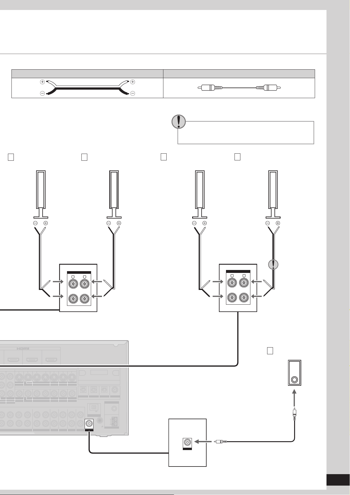
Connection cable
Speaker cable (not included) Monaural connection cable (not included)
Quick guide
Use the terminal for the left surround back
speaker when you place the speakers for 6.1
channel playback.
D
Surround speaker
(right)
E
Surround speaker
SURROUND
SURROUND
L
R
(left)
F
Surround back speaker
(right)
G
Surround back speaker
(left)
SURROUND BACK
SURROUND BACK
L
R
Connecting speakers
IN IN
(DVD RECORDER)
MPONENT VIDEO
IN
(CABLE/SAT)
PLAYER)
2
NTER
SURROUND BACK
WOOFER
BD/DVD PLAYER / ANALOG 8CH IN DVD RECORDER
HDMI 1
OUT OUT
TV MONITOR
OUT
IN
TV MONITOR
3
SURROUND
(BD/DVD PLAYER)
HDMI 2 HDMI 3
IN
BD/
DVD RECORDER
DVD PLAYER
IN
OUT
BD/
DVD PLAYER
DVD RECORDER
AUDIO
FRONT
OUT
IN
(CABLE/SAT)
S VIDEO
IN IN IN IN
VCR
CABLE/SAT
VIDEO
IN IN IN
VCR
CABLE/SAT
IN IN IN
IN IN
CABLE/SAT
VCR
GAME
GAME
GAME
IN
(DVD RECORDER)
(BD/DVD PLAYER)
OPTICAL 2 OPTICAL 3 COAXIAL
OPTICAL 1
DC OUT 5V
500mA MAX
OPTION V 1
OUT
TV
SUBWOOFER
DIGITAL IN
LOOP ANT
GND
Active subwoofer
H
(TV)
(CD)
FM ANT
75
Ω
LOOP
EXT
AM ANT
OUT
SUBWOOFER
11
RQT9224
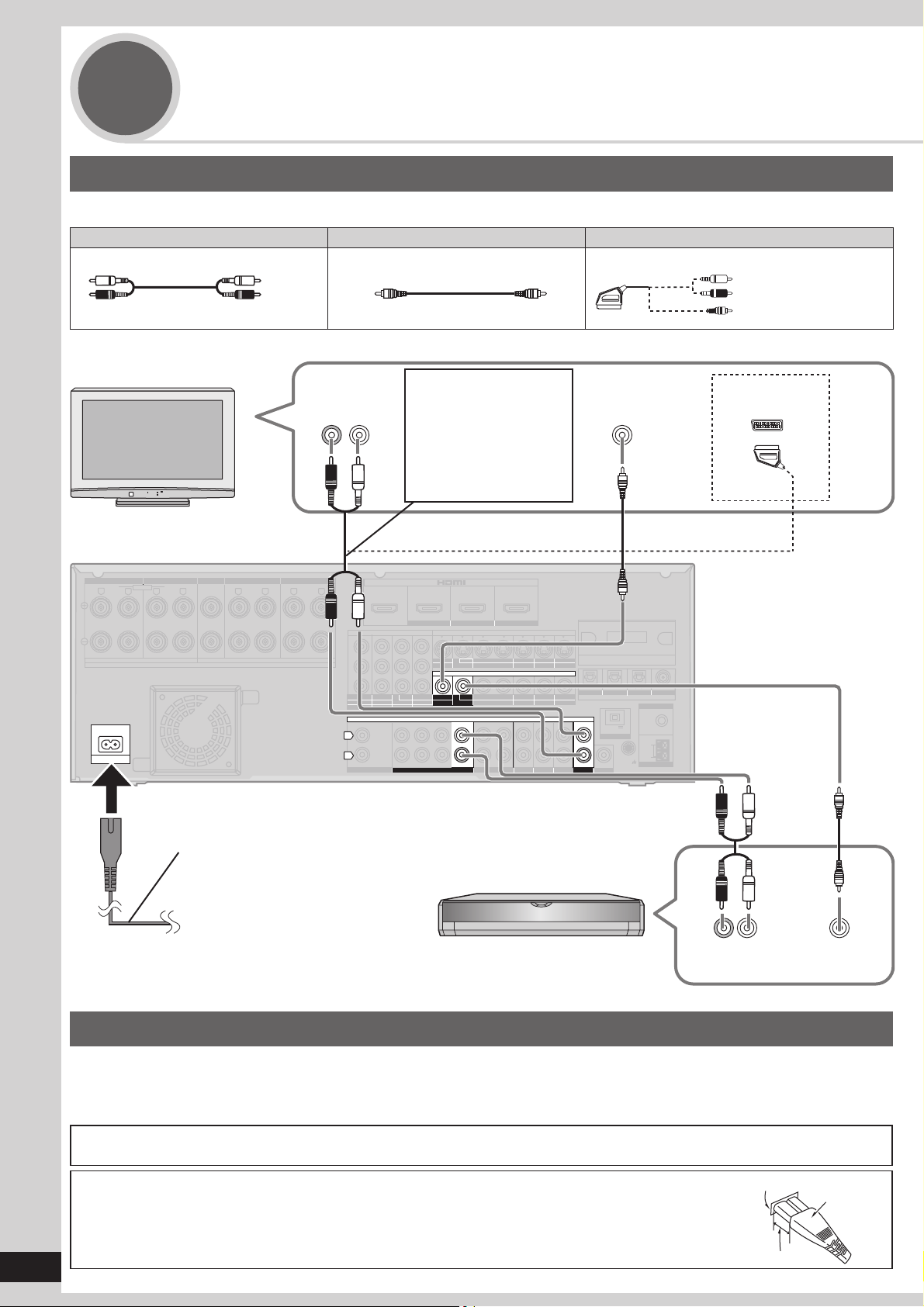
Step
Connecting a TV and a Blu-ray Disc/
3
DVD player
Connecting equipment in the basic way
Connection cable
Audio cable Video cable Video and Audio cable
Stereo phono cable (not included)
White (L)
Red (R)
• When you make HDMI connections, this connection is not necessary.
TV
Rear panel
Video connection cable (not included) 21-pin scart cable (not included)
You need a stereo phono
Audio out
(R) (L)
cable for enjoying TV with
surround sound.
To enjoy TV with a digital
sound output make
connection B instructed
in page 16.
VIDEO
IN
Use when connecting
equipment with a 21-pin
scart terminal.
AV
FRONT A
FRONT A FRONT B CENTER
LF HF
R
A OR B / BI-WIRE (4-16 Ω EACH SPEAKER) A AND B (6-16 Ω EACH SPEAKER)
A
C IN~
FRONT B
BI-WIRE
L
L
R
AC mains lead (included)
CENTER
SURROUND SURROUND BACK
SURROUND
SPEAKERS
L L
(6-16 Ω EACH SPEAKER)
SURROUND BACK
RR
Household mains socket
(AC 220 V to 240 V, 50 Hz)
Y
B
P
R
P
OUT
TV MONITOR
L
R
CD
(DVD RECORDER)
IN
OUT
(DVD RECORDER)
COMPONENT VIDEO
IN
IN
(CABLE/SAT)
DVD PLAYER)
12
CENTER
SURROUND BACK
SUBWOOFER
BD/DVD PLAYER / ANALOG 8CH IN
IN IN
HDMI 1
OUT OUT
TV MONITOR
OUT
IN
TV MONITOR
3
SURROUND
(BD/DVD PLAYER)
HDMI 2 HDMI 3
IN
BD/
DVD PLAYER
IN
BD/(BD/
DVD PLAYER
AUDIO
FRONT
S VIDEO
IN IN IN IN
DVD RECORDER
VIDEO
IN IN IN
OUT
DVD RECORDER
OUT
IN IN
DVD RECORDER
IN
(CABLE/SAT)
VCR
CABLE/SAT
VCR
CABLE/SAT
IN IN IN
CABLE/SAT
VCR
Blu-ray Disc/DVD player
GAME
IN
GAME
GAME
(DVD RECORDER)
(BD/DVD PLAYER)
OPTICAL 2 OPTICAL 3 COAXIAL
OPTICAL 1
DC OUT 5V
500mA MAX
OPTION V 1
OUT
TV
SUBWOOFER
DIGITAL IN
LOOP ANT
GND
(TV)
(CD)
FM ANT
75
Ω
LOOP
EXT
AM ANT
(R) (L)
Audio out
VIDEO
OUT
12
RQT9224
Notes on AC mains lead
• Connect AC mains lead after all other cables and cords are connected.
• The included AC mains lead is for use with this unit only. Do not use it with other equipment.
• Do not use an AC mains lead from any other type of equipment with this unit.
• The unit’s settings remain effective after the AC mains lead is removed from the household mains socket.
FOR THE UNITED KINGDOM AND REPUBLIC OF IRELAND ONLY
READ THE CAUTION FOR THE AC MAINS LEAD ON PAGE 4 BEFORE CONNECTION.
Insertion of connector (Except the United Kingdom and Republic of Ireland)
Even when the connector is perfectly inserted, depending on the type of inlet used, the front part of the
connector may jut out as shown in the drawing.
However there is no problem using the unit.
Appliance inlet
Connector
Approx. 6 mm
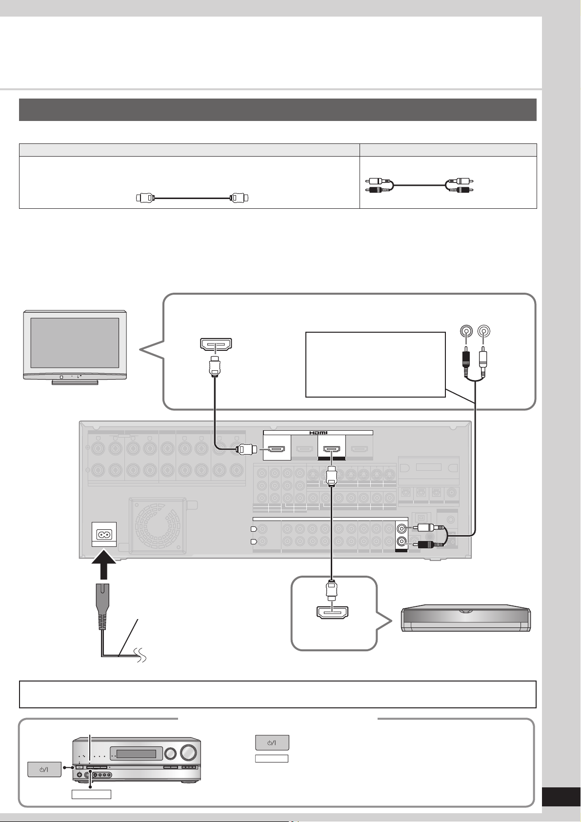
Connecting equipment with HDMI terminal
Connection cable
Video and Audio cable Audio cable
HDMI cable (not included) (It is recommended that you use Panasonic’s HDMI cable.)
Recommended part number:
RP-CDHG10 (1.0 m), RP-CDHG15 (1.5 m), RP-CDHG20
(2.0 m), RP-CDHG30 (3.0 m), RP-CDHG50 (5.0 m), etc.
• This unit incorporates HDMI™ (V.1.3 with Deep Colour) technology that can reproduce greater colour gradation (4096 steps)
when connected to a compatible TV. A lower colour gradation (256 steps), without deep colour, will be reproduced if connected to a
TV which does not support deep colour.
• Please use High Speed HDMI Cables that have the HDMI logo (as shown on the cover).
• When outputting 1080p signal, please use the HDMI cables 5.0 meters or less.
• The audio signal transmitted through HDMI takes priority when you use both HDMI and digital terminals for connection (➜ pages
16, 18 to 20).
Stereo phono cable (not included)
White (L)
Red (R)
Quick guide
TV
Rear panel
FRONT A
FRONT A FRONT B CENTER
R
A OR B / BI-WIRE (4-16 Ω EACH SPEAKER) A AND B (6-16 Ω EACH SPEAKER)
A
C IN~
BI-WIRE
LF HF
L
R
FRONT B
Audio out
(R) (L)
HDMI input
You need a stereo phono cable for
enjoying TV with surround sound.
To enjoy TV with a digital sound
output make connection B
instructed in page 16.
CENTER
SURROUND SURROUND BACK
L
SURROUND
SPEAKERS
L L
(6-16 Ω EACH SPEAKER)
SURROUND BACK
RR
Y
B
P
R
P
TV MONITOR
L
R
OUT
COMPONENT VIDEO
IN
OUT
IN
(DVD RECORDER)
DVD PLAYER)
12
CENTER
IN
SUBWOOFER
CD
BD/DVD PLAYER / ANALOG 8CH IN DVD RECORDER
IN IN
(DVD RECORDER)
HDMI 1
TV MONITOR
IN
(CABLE/SAT)
TV MONITOR
3
SURROUND BACK
(BD/DVD PLAYER)
HDMI 2 HDMI 3
IN
OUT OUT
BD/
DVD PLAYER
OUT
IN
BD/(BD/
DVD PLAYER
AUDIO
SURROUND
FRONT
S VIDEO
IN IN IN IN
DVD RECORDER
VIDEO
IN IN IN
OUT
DVD RECORDER
OUT
IN IN
IN
(CABLE/SAT)
VCR
CABLE/SAT
VCR
CABLE/SAT
IN IN IN
CABLE/SAT
VCR
GAME
GAME
GAME
IN
(DVD RECORDER)
(BD/DVD PLAYER)
OPTICAL 2 OPTICAL 3 COAXIAL
OPTICAL 1
DC OUT 5V
500mA MAX
OPTION V 1
OUT
TV
SUBWOOFER
DIGITAL IN
LOOP ANT
GND
(TV)
(CD)
FM ANT
75
Ω
LOOP
EXT
AM ANT
Connecting a TV and a Blu-ray Disc/DVD player
AC mains lead (included)
HDMI
Household mains socket
Video/Audio out
(AC 220 V to 240 V, 50 Hz)
You can hear DVD sounds, etc. from TV speakers when you turn off the unit connected as shown on this page (standby through
function). This convenient function enables you to enjoy DVD etc. without using the unit late at night.
Blu-ray Disc/DVD player
When connection is complete
SURROUND
“
MULTI CH
TrueHD
D+
DTS-HD
PROCESSING
SURROUND
SPEAKERS A
SETUP MIC
S VIDEO
SURROUND
MULTI CH
LPCM
”
VOLUME
WIRELESS READY
SURROUND M.ROOM
BI-AMP
SPEAKERS B
AUTO SPEAKER SETUP
AUX
L - AUDIO - R
VIDEO
INPUT SELECTOR
_
OK
TUNE
-
SETUP
RETURN
1. Press to turn the unit on.
+
2. Press
• The “SURROUND” indicator lights on after the setting.
• You can enjoy 2-channel sources with surround playback.
SURROUND
to set surround playback.
13
RQT9224
Step
4
“ ”
SURROUND
“
MULTI CH
TrueHD
D+
PROCESSING
SURROUND
SETUP MIC
SURROUND
Watching TV or DVD
Turn the TV on and switch the TV’s input mode (to “HDMI” and others)
”
VOLUME
_
OK
TUNE
+
DTS-HD
SPEAKERS A
INPUT SELECTOR
WIRELESS READY
MULTI CH
SURROUND M.ROOM
BI-AMP
LPCM
SPEAKERS B
AUTO SPEAKER SETUP
AUX
L - AUDIO - R
S VIDEO
VIDEO
SPEAKERS A
-
SETUP
RETURN
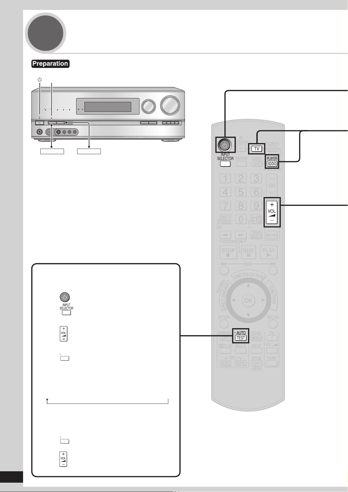
Testing speaker output
You can confi rm audio output using the test signal.
1. Press to turn the unit on.
2. Press to select an input source other than
“TV ” or “BD/DVD P. ”.
3. Press
–30dB and –35dB.
4. Press
connected speakers.
• Speakers are displayed in the following order.
L → C → R → RS → SBR → SBL → LS → SUBW
When you feel the volume of each speaker is not
balanced with the volume of the front speakers, see
page 31 to adjust the volume balance of speakers.
5. Press
6. Lower the volume to the normal listening level
to adjust the volume range between
AUTO
to test audio output from all
TEST
(The test signal is output only when the
connected speaker is displayed.)
AUTO
to stop the test signal.
TEST
14
RQT9224
using .
1
To turn the unit on
Press
To select “TV ” or “BD/DVD P. ”.
• The standby indicator “^” goes off when you turn the unit on.
• Confi rm if “
displayed, press [SPEAKERS A].
• Check the “SURROUND” indicator is lighting up. If not, press
[SURROUND] on the unit to set surround playback (➔ pages 13 and
29).
A
” appears on the display on the unit. If “A” is not
Quick guide
2
3
4
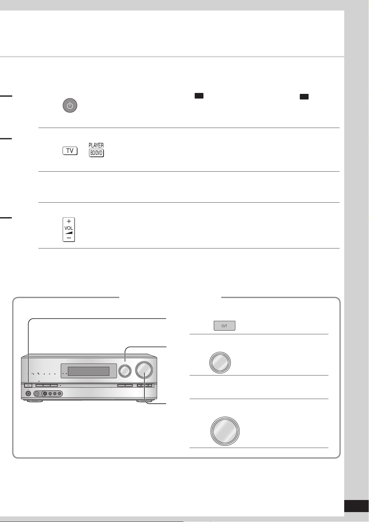
Press or
Watch TV or DVD
• You can enjoy the variety of surround effects (➔ pages 28 to 30).
To adjust the volume
Press
To fi nish watching
Be sure to reduce the volume and press [^] to turn the unit to standby.
Operations on the unit
To turn the unit on
1
Press
Watching TV or DVD
Volume range:
– – dB (minimum), – 79dB to 0dB (maximum)
To select “TV ” or “BD/DVD P. ”
INPUT SELECTOR
WIRELESS READY
MULTI CH
SPEAKERS A
SURROUND M.ROOM
BI-AMP
LPCM
SPEAKERS B
AUTO SPEAKER SETUP
AUX
L - AUDIO - R
S VIDEO
VIDEO
-
SETUP
RETURN
MULTI CH
TrueHD
D+
DTS-HD
PROCESSING
SURROUND
SETUP MIC
VOLUME
_
OK
TUNE
2
Turn
+
Watch TV or DVD
3
INPUT SELECTOR
To adjust the volume
4
VOLUME
Turn
_
+
15
RQT9224
Connections
SURROUND SURROUND BACK
OUT
IN IN
CD
BD/DVD PLAYER / ANALOG 8CH IN DVD RECORDER
VCR
CABLE/SAT
GAME
TV
AUDIO
SURROUND BACK
SURROUND
FRONT
SUBWOOFER
OUT
IN IN
IN
(DVD RECORDER)
(BD/DVD PLAYER)
(CABLE/SAT)
HDMI 1
HDMI 2 HDMI 3
SURROUND
SURROUND BACK
S VIDEO
COMPONENT VIDEO
L
R
IN IN IN
IN
OUT
IN
IN
OUT
IN IN IN
IN
TV MONITOR
TV MONITOR
DVD RECORDER
VCR
CABLE/SAT
GAME
DVD PLAYER
BD/(BD/
DVD PLAYER)
(DVD RECORDER)
(CABLE/SAT)
12
3
(DVD RECORDER)
(BD/DVD PLAYER)
(TV)
(CD)
OPTICAL 1
OPTICAL 2 OPTICAL 3 COAXIAL
SUBWOOFER
Y
P
B
P
R
IN
OUT OUT
IN IN IN IN
TV MONITOR
DVD RECORDER
VCR
CABLE/SAT
GAME
DVD PLAYER
BD/
(6-16 Ω EACH SPEAKER)
OUT
CENTER
IN
IN
FM ANT
AM ANT
OPTION V 1
LOOP
EXT
DC OUT 5V
500mA MAX
75
Ω
RR
L L
LOOP ANT
GND
VIDEO
OUT
DIGITAL IN
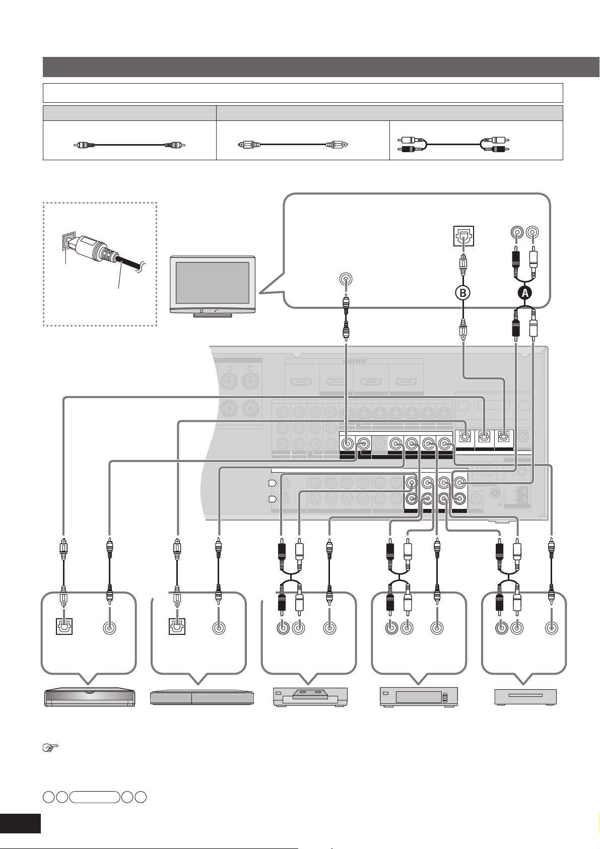
Basic connections
Connecting cables to video and audio terminals (Connecting equipment without HDMI terminal)
Video cable Audio cable
Video connection cable (not included)
Optical fi bre cable (not included) Stereo phono cable
To enjoy TV with surround sound, make connection A
or B instructed below according to your equipment.
(not included)
White (L)
Red (R)
Connecting the optical
fi bre cable
Note the
shape and fi t
it correctly
into the
Do not
bend!
terminal.
TV
Rear panel
VIDEO IN
Digital audio
out (optical)
Audio out
(R) (L)
Digital audio
out (optical)
DVD player
16
RQT9224
To connect a DVD recorder with built-in VCR
• When you make HDMI connections (➔ pages 13 and 17), this connection is not necessary.
• The input video signal can be sent out through an output terminal of the same type only.
• You can change the digital input terminal setting according to the equipment to connect (➔ page 39).
1 2
VIDEO
OUT
(When the DVD recorder has DVD/VHS terminals, make the following connections.)
Connect the DVD output terminal as 1 described above.
Connect the DVD/VHS output terminal as 2 described above.
Note
Digital audio
out (optical)
DVD recorderBlu-ray Disc/
VIDEO
OUT
(R) (L)
Audio out
VIDEO
OUT
VCR
Audio out
Cable box or
satellite receiver
(R) (L)
VIDEO
OUT
(R) (L)
Audio out
Game
VIDEO
OUT
• Turn off all equipment before making any connections.
SURROUND SURROUND BACK
OUT
IN IN
CD
BD/DVD PLAYER / ANALOG 8CH IN DVD RECORDER
VCR
CABLE/SAT
GAME
TV
AUDIO
SURROUND BACK
SURROUND
FRONT
SUBWOOFER
OUT
IN IN
IN
(DVD RECORDER)
(BD/DVD PLAYER)
(CABLE/SAT)
HDMI 1
HDMI 2 HDMI 3
SURROUND
SURROUND BACK
S VIDEO
COMPONENT VIDEO
L
R
IN IN IN
IN
OUT
IN
IN
OUT
OUT
IN IN IN
IN
TV MONITOR
TV MONITOR
DVD RECORDER
VCR
CABLE/SAT
GAME
DVD PLAYER
BD/(BD/
DVD PLAYER)
(DVD RECORDER)
(CABLE/SAT)
12
3
(DVD RECORDER)
(BD/DVD PLAYER)
(TV)
(CD)
OPTICAL 1
OPTICAL 2 OPTICAL 3 COAXIAL
SUBWOOFER
Y
P
B
P
R
IN
OUT OUT
IN IN IN IN
TV MONITOR
DVD RECORDER
VCR
CABLE/SAT
GAME
DVD PLAYER
BD/
(6-16 Ω EACH SPEAKER)
OUT
CENTER
IN
IN
FM ANT
AM ANT
OPTION V 1
LOOP
EXT
DC OUT 5V
500mA MAX
75
Ω
RR
L L
LOOP ANT
GND
VIDEO
DIGITAL IN
• Peripheral equipment sold separately unless otherwise indicated.
• To connect equipment, refer to the appropriate operating instructions.
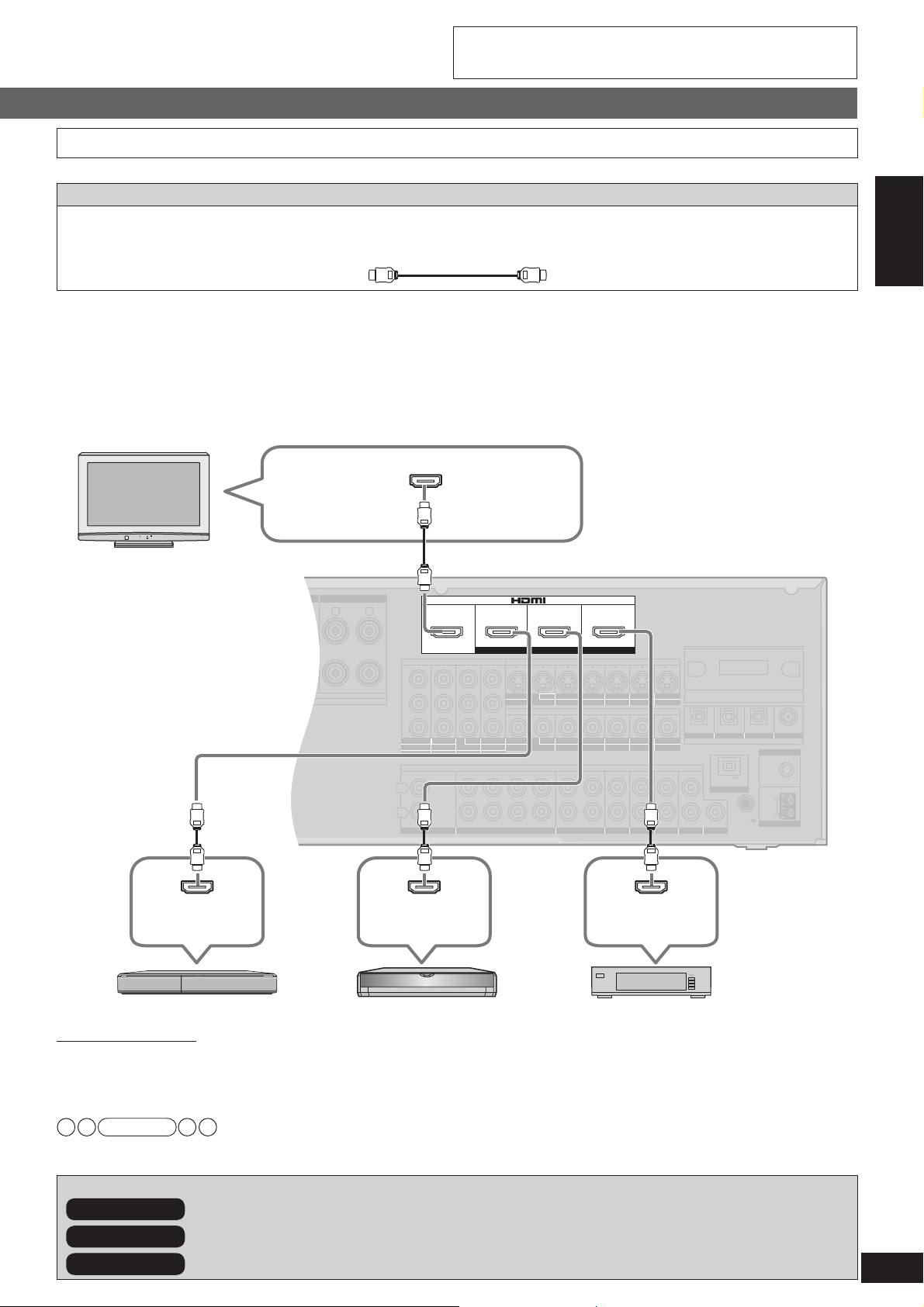
Connecting equipment with HDMI terminal
Connection cable
Video and Audio cable
HDMI cable
(not included)
Recommended part number:
RP-CDHG10 (1.0 m), RP-CDHG15 (1.5 m), RP-CDHG20 (2.0 m), RP-CDHG30 (3.0 m), RP-CDHG50 (5.0 m), etc.
HDMI cable notes
• It is recommended that you use Panasonic’s HDMI cable.
• This unit incorporates HDMI™ (V.1.3 with Deep Colour) technology.
• Please use High Speed HDMI Cables that have the HDMI logo (as shown on the cover).
• When outputting 1080p signal, please use the HDMI cables 5.0 meters or less.
To enjoy TV with surround sound, make connection A or B
TV
instructed on page 16 according to your equipment.
HDMI input
Preparations
Connections
The HDMI input terminal on the unit’s rear is made to specifi cations that presume connection of a DVD recorder / Blu-ray Disc/
DVD player etc. When other equipment is connected, sounds may not come out of the unit, or pictures shown on the equipment (TV)
connected to the HDMI output terminal may be disrupted.
In such cases, see pages 16, 18 and 19 and make connections other than HDMI.
•
The audio signal transmitted through HDMI takes priority when you use both HDMI and digital terminals for connection (➔ pages 16, 18 to 20).
• You can change the settings on HDMI 3 terminal according to the equipment to connect (➔ page 39).
Playback is available with the basic connections (➔ page 26).
HDMI connection
Rear panel
HDMI
Video/Audio out
HDMI
Video/Audio out
DVD recorder Blu-ray Disc/DVD player
Note
Besides To make high-picture-quality connections
Besides To enjoy analogue sounds
Besides To connect other equipment, etc.
(➔ page 20)
(➔ pages 20 to 23)
Cable box, satellite receiver, etc.
(➔ pages 18 and 19)
HDMI
Video/Audio out
17
RQT9224
 Loading...