

Panasonic SABTT-755-GN, SABTT-350-GN Service manual
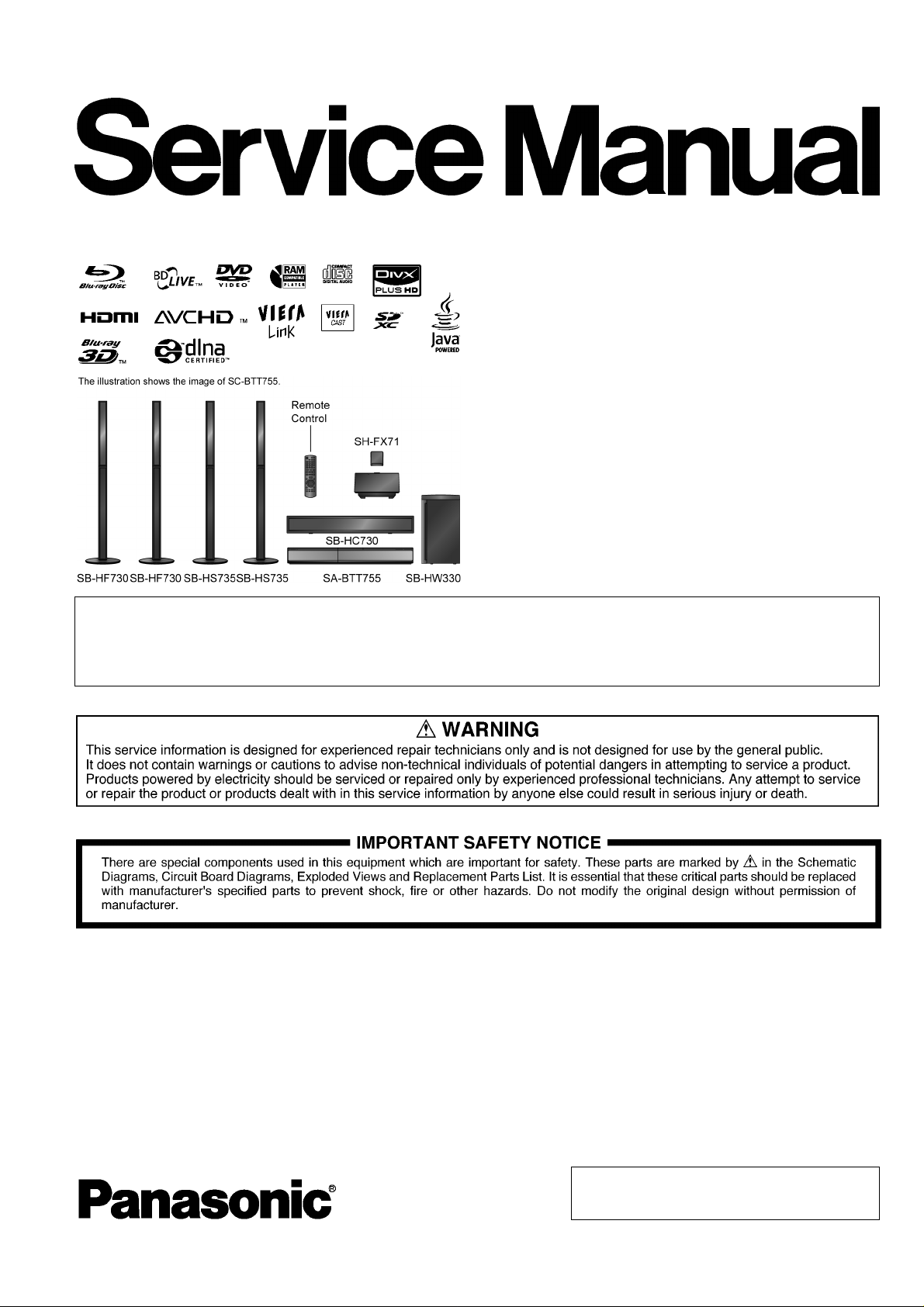
PSG1008005CE
Blu-ray Disc Home Theater Sound System
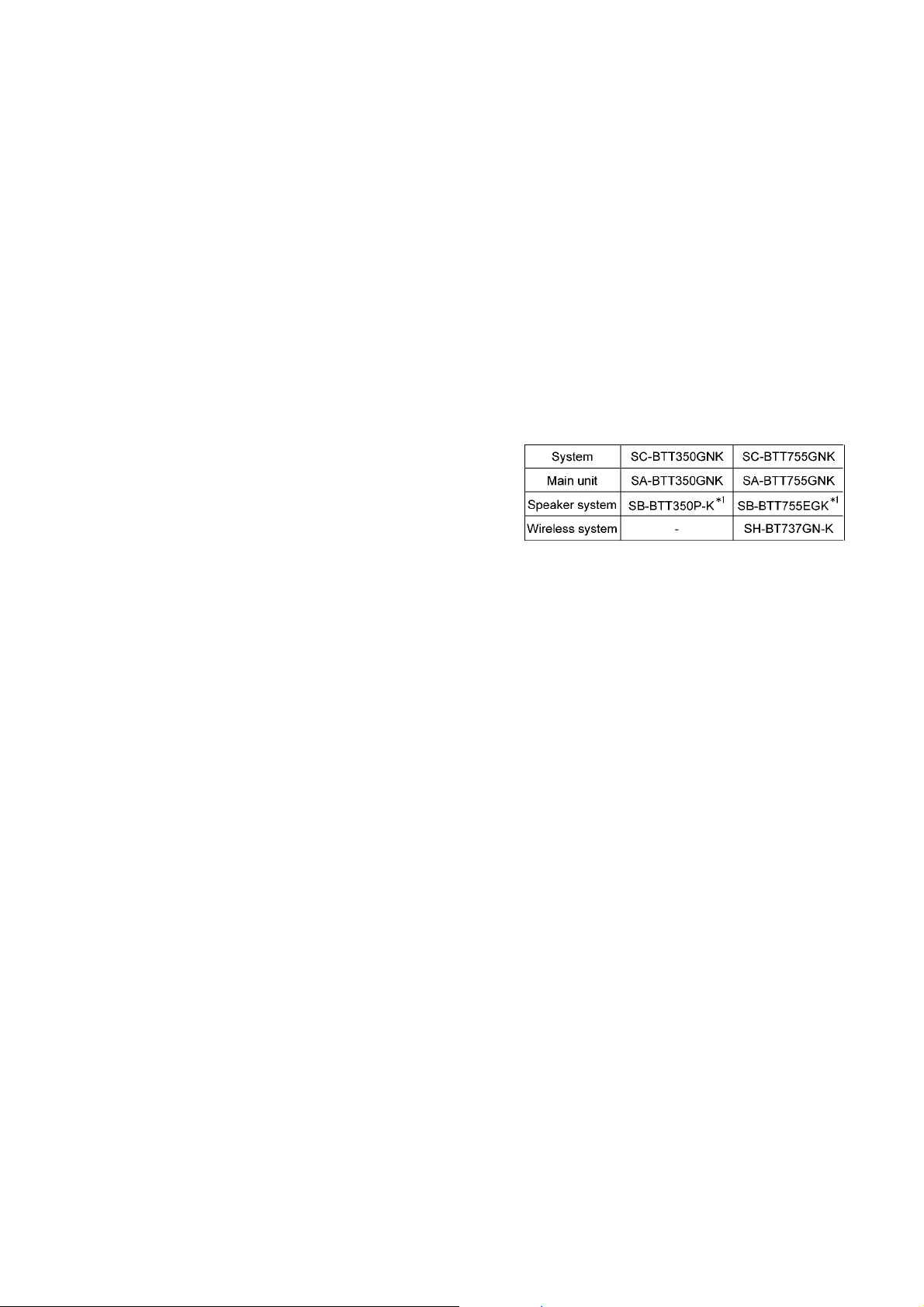
Model No. SA-BTT350GN
SA-BTT755GN
Vol.1
Product Color: (K)...Black Type
Notes: Please refer to the original service manual for:
• Speaker system SB-BTT350P-K (For SA-BTT350GNK), Order No: PSG1007005CE.
• Speaker system SB-BTT755EGK (For SA-BTT755GNK), Order No: PSG1008001CE.
• Wireless system SH-BT737GN-K (For SA-BTT755GNK), Order No: PSG1004059AE.
TABLE OF CONTENTS
PAGE PAGE
1 Safety Precautions----------------------------------------------- 3
1.1. GENERAL GUIDELINES-------------------------------- 3
1.2. Before Repair and Adjustment-------------------------3
1.3. Protection Circuitry---------------------------------------- 3
1.4. Safety Parts Information---------------------------------5
2 Warning-------------------------------------------------------------- 6
2.1. Prevention of Electrostatic Discharge (ESD)
to Electrostatic Sensitive (ES) Devices -------------- 6
2.2. Precaution of BD Drive -----------------------------------7
2.3. Service caution based on Legal restrictions --------8
2.4. Grounding for electrostatic breakdown
prevention----------------------------------------------------8
3 Service Navigation -----------------------------------------------9
3.1. Service Information----------------------------------------9
3.2. Firmware updates------------------------------------------9
3.3. Caution for Replacing Parts--------------------------- 10
© Panasonic Corporation 2010. All rights reserved.
Unauthorized copying and distribution is a violation
of law.

4 Specifications---------------------------------------------------- 11
4.1. Others (Licenses) ----------------------------------------12
5 Location of Controls and Components------------------13
5.1. Remote Control Key Button Operations------------13
5.2. Main Unit Key Button Operations --------------------14
5.3. Connection to a Broadband Network ---------------15
5.4. Network Easy Setting-----------------------------------16
5.5. Firmware Updates ---------------------------------------18
5.6. Using BD-LIVE or BONUSVIEW in BD-Video ----19
5.7. Enjoying Blu-ray 3D Video-----------------------------20
5.8. Using the iPod/iPhone ----------------------------------21
5.9. Enjoying VIERA CAST™-------------------------------23
5.10. Speaker Connections -----------------------------------24
5.1 1 . Disc/Card Playability ------------------------------------25
5.12. File Extension Type Support (MP3/JPEG/
DivX/AVCHD/MPEG2 files)----------------------------27
6 Operating Instructions----------------------------------------29
6.1. Removing of disc during abnomality ---------------- 29
7 Self-Diagnostic and Special Mode Setting -------------30
7.1. Special Mode Table 1 -----------------------------------30
7.2. Special Mode Table 2 -----------------------------------31
7.3. Error Code Table -----------------------------------------32
7.4. Service Mode----------------------------------------------34
8 Troubleshooting Guide----------------------------------------39
8.1. Troubleshooting Guide for F61 and/or F76--------39
9 Service Fixture & Tools---------------------------------------43
9.1. Service Tools and Equipment-------------------------43
10 Disassembly and Assembly Instructions---------------44
10.1. Disassembly Flow Chart--------------------------------45
10.2. Main Components and P.C.B. Locations----------- 46
10.3. Disassembly of Top Cabinet---------------------------47
10.4. Disassembly of AC Inlet P.C.B.-----------------------48
10.5. Disassembly of Wireless Adapter P.C.B.----------- 48
10.6. Disassembly of Fan--------------------------------------50
10.7. Disassembly of Rear Panel----------------------------51
10.8. Disassembly of Front Panel Assembly -------------51
10.9. Dissassembly of FL P.C.B.-----------------------------52
10.10. Dissassembly of Power Button P.C.B.--------------54
10.11. Replacement of Cradle Lid ----------------------------55
10.12. Disassembly of iPod Cradle Assembly-------------56
10.13. Disassembly of iPod P.C.B.----------------------------58
10.14. Replacement of DVD Lid Unit-------------------------58
10.15. Disassembly of Main P.C.B.---------------------------61
10.16. Disassembly of Digital P.CB.--------------------------62
10.17. Disassembly of BD Drive-------------------------------65
10.18. Disassembly of D-Amp P.C.B. ------------------------70
10.19. Replacement of Digital Amplifier IC (IC5100/
IC5200) -----------------------------------------------------71
10.20. Disassembly of Power P.C.B.-------------------------72
10.21. Disassembly of SMPS P.C.B.-------------------------72
10.22. Replacement of Switching Regulator IC
(IC5701) ----------------------------------------------------74
10.23. Replacement of Rectifier Diode (D5702)-----------75
10.24. Replacement of Regulator Diode (D5802)---------76
10.25. Replacement of Regulator Diode (D5803)---------77
11 Service Position -------------------------------------------------79
11.1. Checking & Repairing Side A of Main P.C.B. -----79
11.2. Checking & Repairing Side B of Main P.C.B. -----79
11.3. Checking & Repairing D-Amp P.C.B.----------------80
11.4. Checking & Repairing SMPS P.C.B. ----------------81
11.5. Checking & Repairing FL P.C.B. ---------------------83
12 Voltage & Waveform Chart ---------------------------------- 84
12.1. Main P.C.B. (1/5)----------------------------------------- 84
12.2. Main P.C.B. (2/5)----------------------------------------- 85
12.3. Main P.C.B. (3/5)----------------------------------------- 86
12.4. Main P.C.B. (4/5)----------------------------------------- 87
12.5. Main P.C.B. (5/5)----------------------------------------- 88
12.6. FL P.C.B. -------------------------------------------------- 89
12.7. D-Amp P.C.B. (1/2)-------------------------------------- 90
12.8. D-Amp P.C.B. (2/2)-------------------------------------- 91
12.9. Power P.C.B. --------------------------------------------- 91
12.10. SMPS P.C.B. --------------------------------------------- 92
12.1 1. Waveform Table (1/2)----------------------------------- 93
12.12. Waveform Table (2/2)----------------------------------- 94
13 Illustration of ICs, Transistor and Diode---------------- 95
14 Simplified Block Diagram------------------------------------ 97
15 Block Diagram--------------------------------------------------- 98
15.1. System Control------------------------------------------- 98
15.2. Audio & Video -------------------------------------------- 99
15.3. IC Terminal Chart (Audio & Video) -----------------101
15.4. Power Supply(Main Section) ------------------------102
16 Wiring Connection Diagram -------------------------------104
17 Schematic Diagram-------------------------------------------105
17.1. Schematic Diagram Notes ---------------------------105
17.2. Main Circuit-----------------------------------------------107
17.3. D-Amp Circuit--------------------------------------------115
17.4. SMPS Circuit---------------------------------------------119
17.5. Power, Power Button & AC Inlet Circuit-----------121
17.6. iPod & Wireless Adapter Circuit --------------------122
17.7. FL Circuit--------------------------------------------------123
18 Printed Circuit Board-----------------------------------------124
18.1. Main P.C.B.-----------------------------------------------124
18.2. D-Amp P.C.B.--------------------------------------------126
18.3. SMPS P.C.B.---------------------------------------------127
18.4. Power, Power Button, AC Inlet & iPod P.C.B.---128
18.5. Wireless Adapter & FL P.C.B. -----------------------129
19 Terminal Function of ICs------------------------------------131
19.1. IC6001(C0HBB0000057): IC FL Driver-----------131
20 Exploded View and Replacement Parts List----------133
20.1. Exploded View and Mechanical replacement
Part List ---------------------------------------------------133
20.2. Electrical Replacement Part List--------------------139
2
1 Safety Precautions
1.1. GENERAL GUIDELINES
1. When servicing, observe the original lead dress. If a short circuit is found, replace all parts which have been overheated or
damaged by the short circuit.
2. After servicing, see to it that all the protective devices such as insulation barriers, insulation papers shields are properl y
installed.
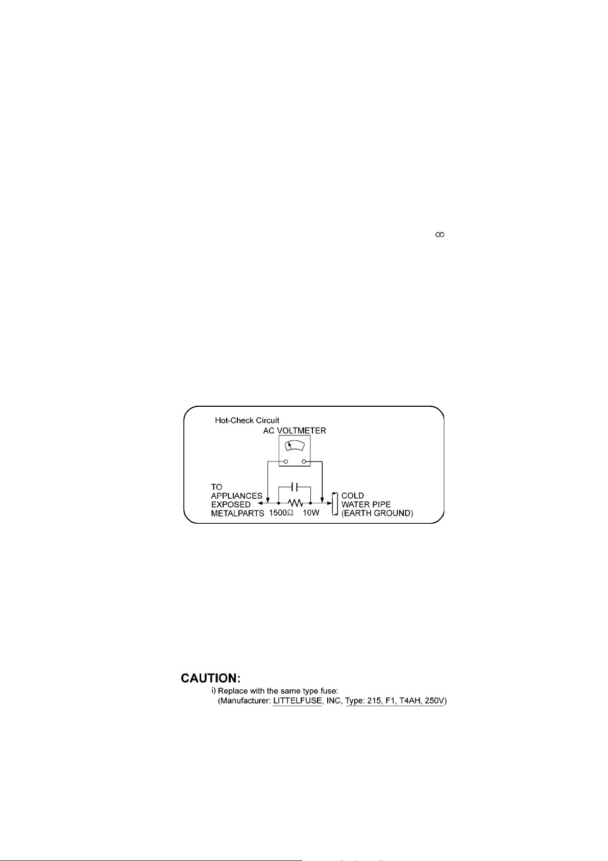
3. After servicing, carry out the following leakage current checks to prevent the customer from being exposed to shock hazards.
1.1.1. LEAKAGE CURRENT COLD CHECK
1. Unplug the AC cord and connect a jumper between the two prongs on the plug.
2. Measure the resistance value, with an ohmmeter, between the jumpered AC plug and each exposed metallic cabinet part on
the equipment such as screwheads, connectors, control shafts, etc. When the exposed metallic part has a return path to th e
chassis, the reading should be between 1MΩ and 5.2MΩ.
When the exposed metal does not have a return path to the chassis, the reading must be
1.1.2. LEAKAGE CURRENT HOT CHECK
1. Plug the AC cord directly into the AC outlet. Do not use an isolation transformer for this check.
2. Connect a 1.5kΩ, 10 watts resistor, in parallel with a 0.15µF capacitors, between each exposed metallic part on the set and a
good earth ground such as a water pipe, as shown in Figure 1.
3. Use an AC voltmeter, with 1000 ohms/volt or more sensitivity, to measure the potential across the resistor.
4. Check each exposed metallic part, and measure the voltage at each point.
5. Reverse the AC plug in the AC outlet and repeat each of the above measurements.
6. The potential at any point should not exceed 0.75 volts RMS. A leakage current tester (Simpson Model 229 or equiva lent)
may be used to make the hot checks, leakage current must not exceed 1/2 milliamp. In case a measurement is outside of the
limits specified, there is a possibility of a shock hazard, and the equipment should be repaired and rechecked before it is
returned to the customer.
Figure 1
1.2. Before Repair and Adjustment
Disconnect AC power to discharge unit AC Capacitors as such (C5700, C5701, C5702, C5703, C5705, C5706) through a 10 Ω, 10
W resistor to ground.
Caution:
DO NOT SHORT-CIRCUIT DIRECTLY (with a screwdriver blade, for instance), as this may destroy solid state devices.
After repairs are completed, restore power gradually using a variac, to avoid overcurrent.
Current consumption at AC 240 V, 60 Hz in NO SIGNAL mode volume minimal should be ~ 600 mA.
1.2.1. Caution for fuse replacement
1.3. Protection Circuitry
The protection circuitry may have operated if either of the following conditions are noticed:
• No sound is heard when the power is turned on.
• Sound stops during a performance.
The function of this circuitry is to prevent circuitry damage if, for example, the positive and negative speaker connection wires are
“shorted”, or if speaker systems with an impedance less than the indicated rated impedance of the amplifier are used.
3

If this occurs, follow the procedure outlines below:
1. Turn off the power.
2. Determine the cause of the problem and correct it.
3. Turn on the power once again after one minute.
Note:
When the protection circuitry functions, the unit will not operate unless the power is first turned off and then on again.
4

1.4. Safety Parts Information
Safety Parts List:
There are special components used in this equipment which are important for safety.
These parts are marked by ( ) in the Schematic Diagrams & Replacement Parts List. It is essential that these critical parts
should be replaced with manufacturer’s specified parts to prevent shock, fire or other hazards. Do not modify the original design
without permission of manufacturer.
Safety Ref. No. Part No. Part Name & Description Remarks
9 REX1395-1 1P BLACK WIRE (AC INLET-SMPS)
10 REX1396-1 1P RED WIRE (AC INLET-SMPS)
20 RGR0408A-B2A REAR PANEL BTT350GN
20 RGR0408A-D2A REAR PANEL BTT755GN
32-3 RXQX1013 SMPS BOTTOM PC SHEET UNIT
33 RKM0635-K TOP CABINET
54 VXY2119 BD DRIVE
101 VQL1V70-J LASER CAUTION LABEL
A2 K2CJ2DA00010 AC CORD
A3 VQT2W23 O/I BOOK (En)
PCB7 REPX0875BA SMPS P.C.B. (ESD)
PCB8 REPX0875BA AC INLET P.C.B. (ESD)
DZ5701 ERZV10V511CS ZNR
L5702 ELF21N015A LINE FILTER
L5703 ELF21N015A LINE FILTER
T5701 ETS42BM1H6AC MAIN TRANSFORMER
T5751 ETS19AB2A6AG SUB TRANSFORMER
T6100 G4D1A0000142 SWITCHING TRANSFORMER
PC5702 B3PBA0000503 PHOTO COUPLER
PC5720 B3PBA0000503 PHOTO COUPLER
PC5799 B3PBA0000503 PHOTO COUPLER
RY701 K6B1AEA00003 RELAY
F1 K5D402BNA005 FUSE
TH5702 D4CAA5R10001 THERMISTOR
P5701 K2AA2B000011 AC INLET
C5700 F1BAF1020020 1000pF
C5701 F0CAF104A105 0.1uF
C5702 F0CAF104A105 0.1uF
C5703 F0CAF104A105 0.1uF
C5705 F1BAF1020020 1000pF
C5706 F1BAF471A013 470pF
(RTL)
(RTL)
5

2Warning
2.1. Prevention of Electrostatic Discharge (ESD) to Electrostatic Sensitive (ES) Devices
Some semiconductor (solid state) devices can be damaged easily by static electricity. Such components commonly are called Electrostatically Sensitive (ES) Devices. Examples of typical ES devices are integrated circuits and some field-effect transistors and
semiconductor “chip” components. The following techniques should be used to help reduce the incidence of component damage
caused by electrostatic discharge (ESD).
1. Immediately before handling any semiconductor component or semiconductor-equipped assembly, drain off any ESD on your
body by touching a known earth ground. Alternatively, obtain and wear a commercially available discharging ESD wrist strap,
which should be removed for potential shock reasons prior to applying power to the unit under test.
2. After removing an electrical assembly equipped with ES devices, place the assembly on a conductive surface such as aluminum foil, to prevent electrostatic charge buildup or exposure of the assembly.
3. Use only a grounded-tip soldering iron to solder or unsolder ES devices.
4. Use only an anti-static solder removal device. Some solder removal devices not classified as “anti-static (ESD protected)” can
generate electrical charge sufficient to damage ES devices.
5. Do not use freon-propelled chemicals. These can generate electrical charges sufficient to damage ES devices.
6. Do not remove a replacement ES device from its protective package until immediately before you are ready to install it. (Most
replacement ES devices are packaged with leads electrically shorted together by conductive foam, aluminum foil or comparable conductive material).
7. Immediately before removing the protective material from the leads of a replacement ES device, touch the protective material
to the chassis or circuit assembly into which the device will be installed.
Caution:
Be sure no power is applied to the chassis or circuit, and observe all other safety precautions.
8. Minimize bodily motions when handling unpackaged replacement ES devices. (Otherwise harmless motion such as the
brushing together of your clothes fabric or the lifting of your foot from a carpeted floor can generate static electricity (ESD) sufficient to damage an ES device).
6
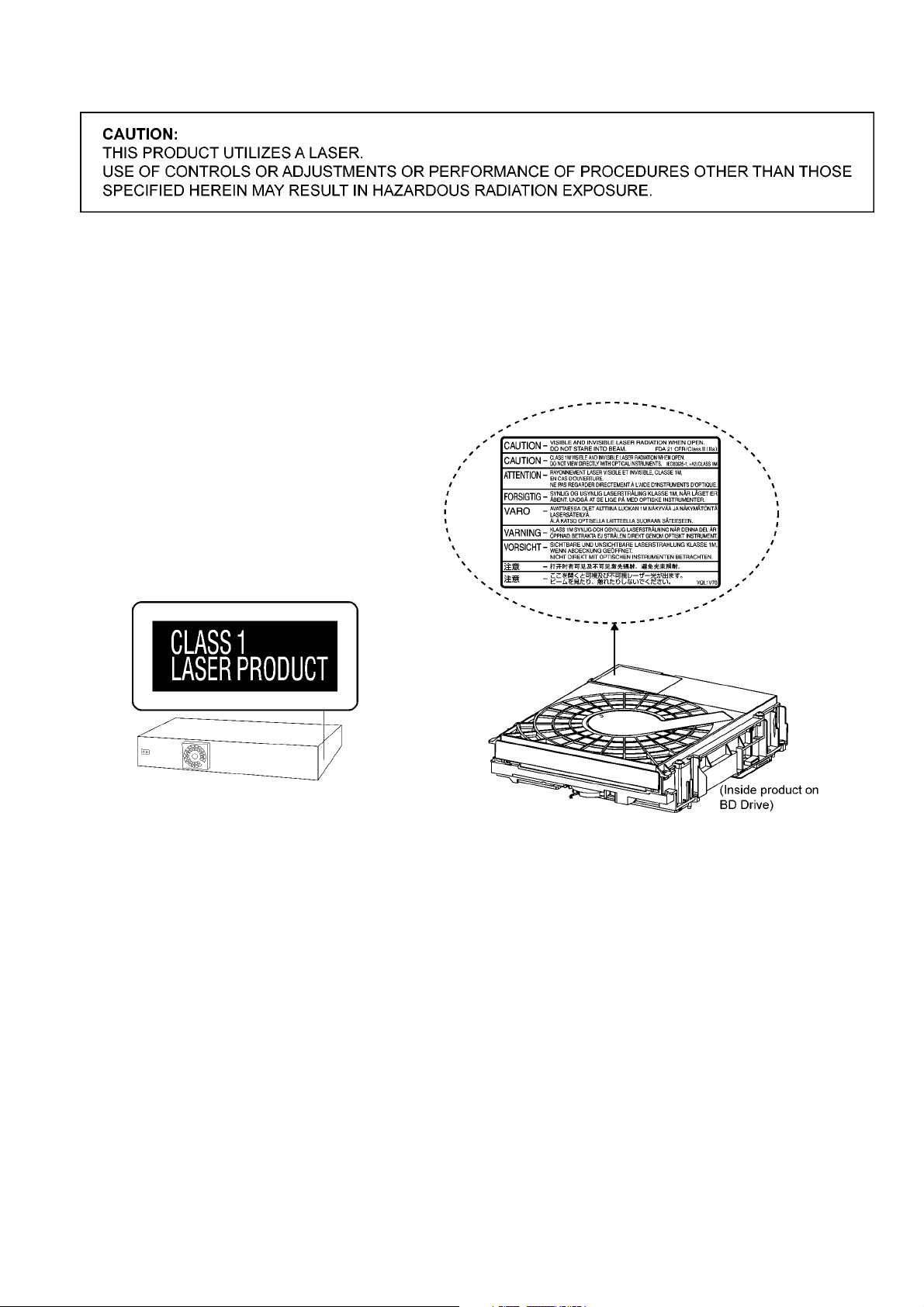
2.2. Precaution of BD Drive
Caution:
This product utilizes a laser diode with the unit turned “on”, invisible laser radiation is emitted from the pickup lens.
Wavelength: 790 nm (CDs), 655 nm (DVDs), 405 nm (BDs)
Maximum output radiation power from pickup: 100 µW/VDE
Laser radiation from the pickup unit is safety level, but be sure the followings:
1. Do not disassemble the pickup unit, since radiation from exposed laser diode is dangerous.
2. Do not adjust the variable resistor on the pickup unit. It was already adjusted.
3. Do not look at the focus lens using optical instruments.
4. Recommend not to look at pickup lens for a long time.
7
2.3. Service caution based on Legal restrictions
2.3.1. General description about Lead Free Solder (PbF)
The lead free solder has been used in the mounting process of all electrical compone nts on the printed circuit boards used for this
equipment in considering the globally environmental conservation.
The normal solder is the alloy of tin (Sn) and lead (Pb). On the other hand, the lead free solder is the alloy mainl y consists of tin
(Sn), silver (Ag) and Copper (Cu), and the melting point of the lead free solder is higher approx.30 degrees C (86°F) more than that
of the normal solder.
Definition of PCB Lead Free Solder being used
The letter of “PbF” is printed either foil side or components side on the PCB using the lead free solder.
(See right figure)
Service caution for repair work using Lead Free Solder (PbF)
• The lead free solder has to be used when repairing the equipment for which the lead free solder is used.
(Definition: The letter of “PbF” is printed on the PCB using the lead free solder.)
• To put lead free solder, it should be well molten and mixed with the original lead free solder.
• Remove the remaining lead free solder on the PCB cleanly for soldering of the new IC.
• Since the melting point of the lead free solder is higher than that of the normal lead solder, it takes the longer time to melt the
lead free solder.
• Use the soldering iron (more than 70W) equi pped with the temperature co ntrol after setting the temp erature at 350±30 degrees
C (662±86°F).
Recommended Lead Free Solder (Service Parts Route.)
• The following 3 types of lead free solder are available through the service parts route.
RFKZ03D01K-----------(0.3mm 100g Reel)
RFKZ06D01K-----------(0.6mm 100g Reel)
RFKZ10D01K-----------(1.0mm 100g Reel)
Note
* Ingredient: tin (Sn), 96.5%, silver (Ag) 3.0%, Copper (Cu) 0.5%, Cobalt (Co) / Germanium (Ge) 0.1 to 0.3%
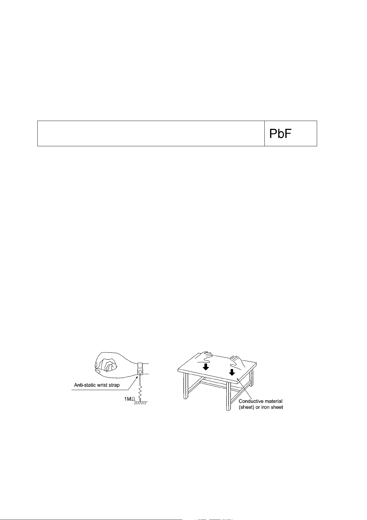
2.4. Grounding for electrostatic breakdown prevention
Some devices such as the DVD player use the optical pickup (laser diode) and the optical pickup will be damaged by static electricity in the working environment. Proceed servicing works under the working environment where grounding works is completed.
2.4.1. Worktable grounding
1. Put a conductive material (sheet) or iron sheet on the area where the optical pickup is placed, and ground the sheet.
2.4.2. Human body grounding
1. Use the anti-static wrist strap to discharge the static electricity form your body.
Figure 2
8
3 Service Navigation
3.1. Service Information
This service manual contains technical information which will allow service personnel’s to understand and service this model.
Please place orders using the parts list and not the drawing reference numbers.
If the circuit is changed or modified, this information will be followed by supplement service manual to be filed with the orig inal service manual.
1) This service manual does not contain the following information, due to the impossib il i ty o f servic i n g at
component level.
O Schematic Diagram, Block Diagram & P. C.B. Layout of Digital P.C.B. & Drive P.C.B..
O Replacement Parts List for individual parts of Digital P.C.B. & Drive P.C.B..
O Exploded View and Parts List for Traverse Unit.
2) The following category are recycle module part. Please send them to Central Repair Center.
- Digital P.C.B. Kit Assembly: RFKB4646CT
- BD Drive: VXY2119
3.2. Firmware updates
9
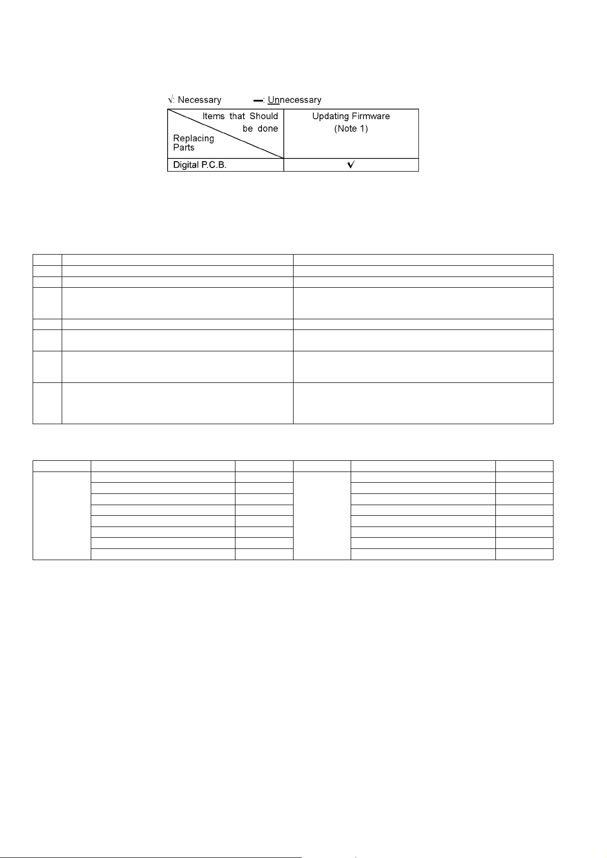
3.3. Caution for Replacing Parts
3.3.1. Items that should be done after replacing parts
Note 1:
Download latest Firmware and burn it on CD-R or CD-RW, and update Firmware.
3.3.2. Standard Inspection Specifications after Making Repairs
After making repairs, we recommend performing the following inspection, to check normal operation.
No. Procedure Item to Check
1 Turn on the power, and confirm items pointed out. Items pointed out should reappear.
2 Insert RAM disc. The Panasonic RAM disc should be recognized.
4 Perform playback for one minute using the RAM disc. No abnormality should be seen in the picture, sound or operation.
5 Perform playback for one minute using the BD-Video disc. No abnormality should be seen in the picture, sound or operation.
6 If a problem is caused by a BD-Video disc, VCD, DVD-R, DVD-
Video, Audio-CD, or MP3, playback the test disc.
7 After checking and making repairs, upgrade the firmware to the
latest version.
8 Transfer [9][9] in the service mode setting, and initialize the ser-
vice settings (return various settings and error information to
their default values. The laser time is not included in this initialization).
*Panasonic DVD-RAM disc should be used when recording and playback.
No abnormality should be seen in the picture, sound or operation.
Make sure that [UPD OK] appears in the FL displays.
*[UNSUPPORT] display means the unit is already updated to newest
same version. Then version up is not necessary.
Make sure that [CLR] appears in the FL display.
After checking it, turn the power off.
Use the following checklist to establish the judgment criteria for the picture and sound.
Item Contents Check Item Contents Check
Picture Block noise Sound Distorted sound
Crosscut noise Noise (static, background noise, etc.)
Dot noise The sound level is too low.
Picture disruption The sound level is too high.
Not bright enough The sound level changes.
Too bright
Flickering color
Color fading
10
4 Specifications
Main unit SA-BTT350GNK, SA-BTT755GNK
OGENERAL
Power supply: AC 220 V to 240 V, 50 Hz
Power consumption: 100 W
Power consumption in standby mode:
0.2 W
iPod/iPhone Connector: DC OUT 5V 500mA MAX
WIRELESS LAN Connector: DC OUT 5V 500mA
(USB 2.0 Standard)
Dimensions (W×H×D): 430 mm×62 mm×287 mm
Mass (Weight): Approx. 3.5 kg
(Dimensions and Weight do not
include Speakers)
Operating temperature range: 0 °C to 40 °C
Operating humidity range: 35 % to 80 % RH
(no condensation)
OAMPLIFIER SECTION
RMS TTL Power Output: 1000 W
1 kHz, 10 % total harmonic distortion
Front:
125 W per ch (3 Ω)
Center:
250 W per ch (6 Ω)
Surround:
125 W per ch (3 Ω)
100 Hz, 10 % total harmonic distortion
Subwoofer:
250 W per ch (6 Ω)
DIN TTL Power Output: 590 W
1 kHz, 1.0 % total harmonic distortion
Front:
90 W per ch (3 Ω)
Center:
115 W per ch (6 Ω)
Surround:
90 W per ch (3 Ω)
45 Hz to 120 Hz, 1.0 % total harmonic distortion
Subwoofer:
115 W per ch (6 Ω)
OFM TUNER SECTION
Present Memory: 30 Stations
Frequency range:
87.50 MHz to 108.00 MHz (50 kHz step)
Antenna terminals: 75 Ω (unbalanced)
OVIDEO SECTION
Signal system: PAL/NTSC
Video output
Output level: 1.0 Vp-p (75 Ω)
Output connector: Pin jack (1 system)
HDMI AV output
Output format:
1080p/ 1080i/ 720p/ 480p
Output connector: Type A (19 pin)
HDMI (with 3D, ARC, Content Type)
This unit supports “HDAVI Control 5” function.
LASER Specification
Class I LASER Product
Wave length:
790 nm (CDs)/655 nm (DVDs)/405 nm (BDs)
Laser power:
No hazardous radiation is emitted with the safety protection
TERMINAL SECTION
USB:
(Front) USB 2.0 High Speed
USB port power: DC OUT 5 V 500mA MAX
Bit rate: Up to 4 Mbps (DivX)
(Rear) USB 2.0 (Use for Wireless LAN
Adaptor only)
Ethernet:
10BASE-T/100BASE-TX
1 system
SD card slot:
Connector: 1 system
Audio input
AUX x 1
Digital audio input
Optical: x 1
Sampling frequency: 32 kHz, 44.1 kHz, 48 kHz
Audio Format: PCM, Dolby Digital
Note:
1. Specifications are subject to change without notice.
Mass and dimensions are approximate.
2. Total harmonic distortion is measured by the digital spectrum
analyzer.
Solder:
This model uses lead free solder (PbF).
Refer to their respective original service manuals for *1.
11
4.1. Others (Licenses)
12
5 Location of Controls and Components
5.1. Remote Control Key Button Operations
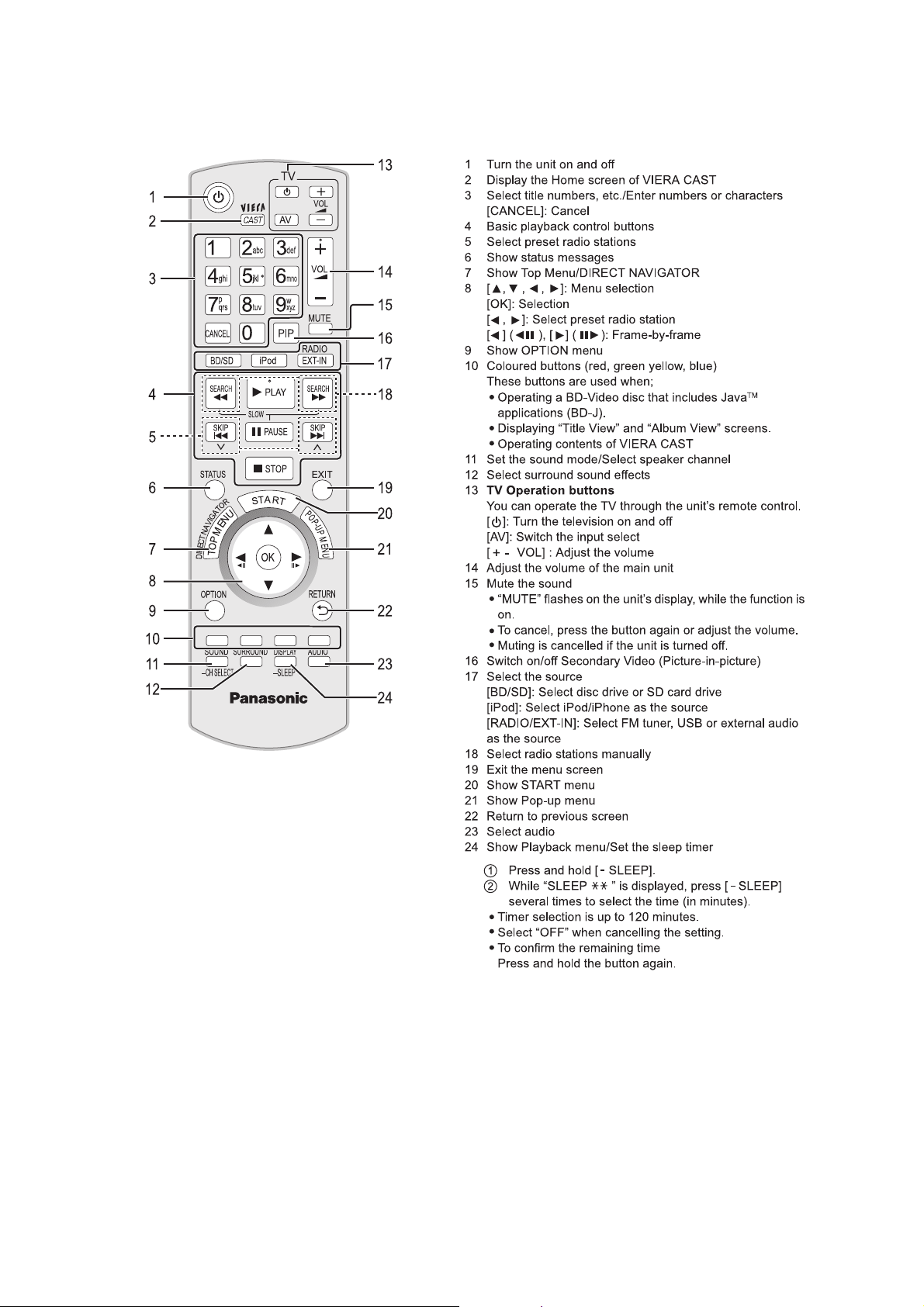
13
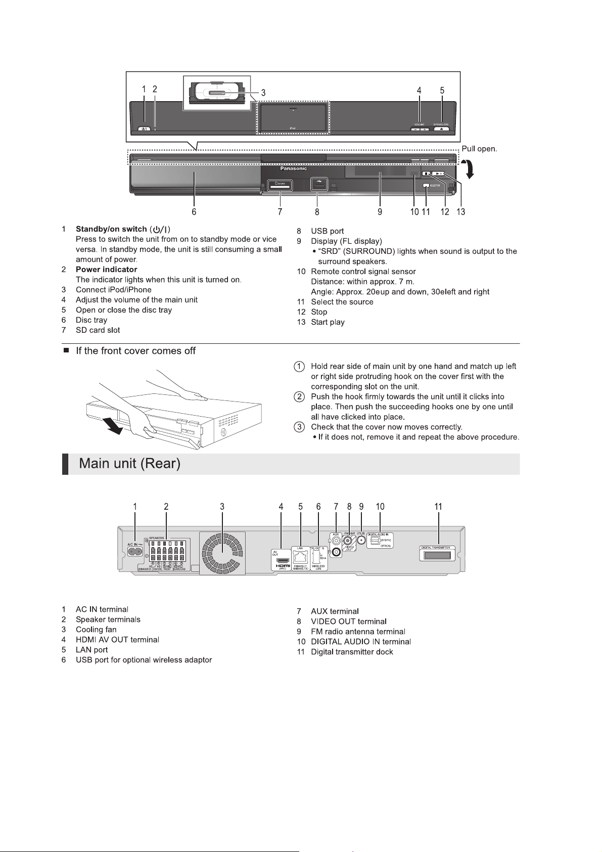
5.2. Main Unit Key Button Operations
14
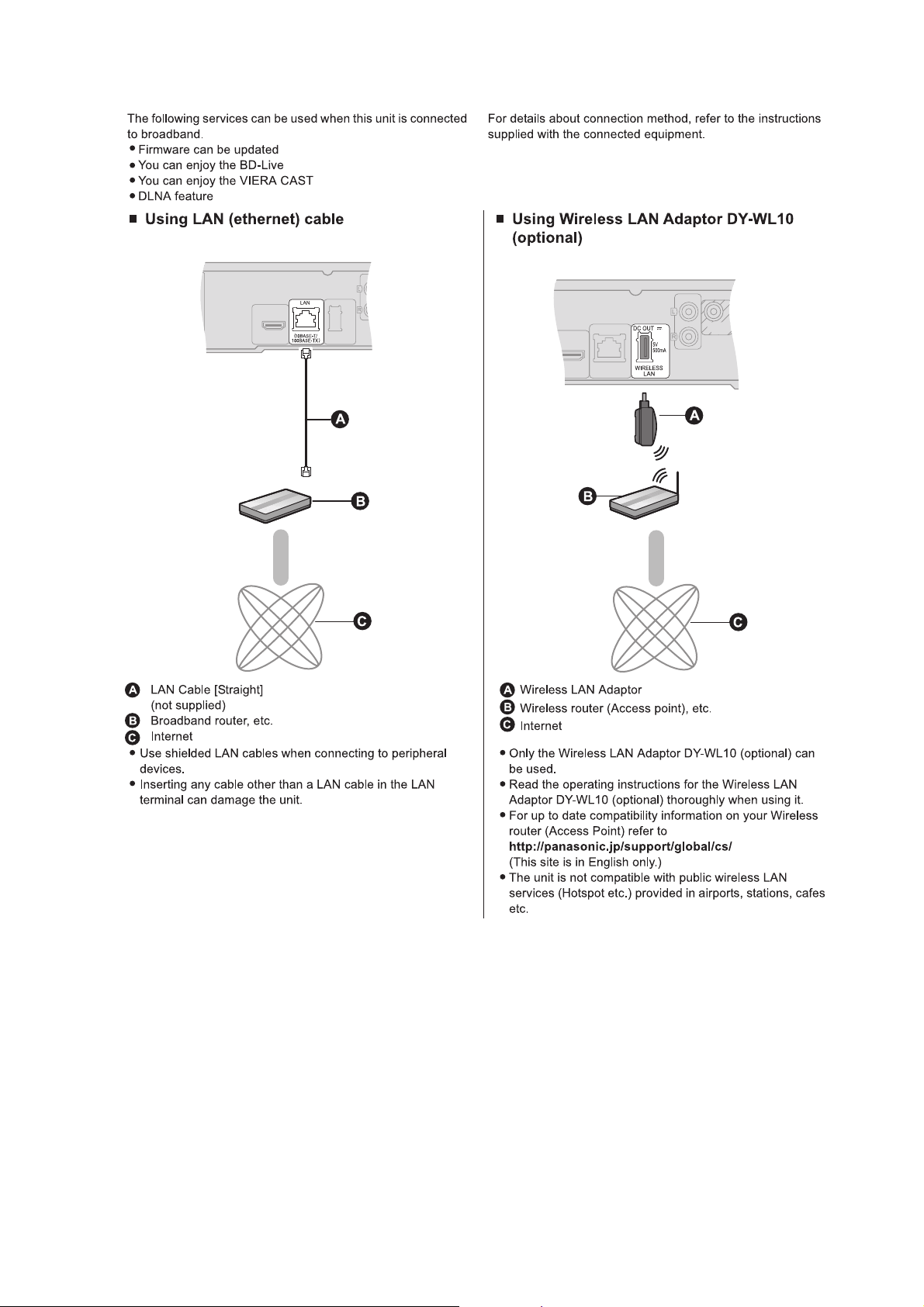
5.3. Connection to a Broadband Network
15
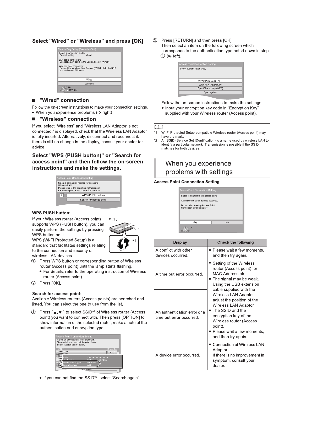
5.4. Network Easy Setting
16
17
5.5. Firmware Updates
18
5.6. Using BD-LIVE or BONUSVIEW in BD-Video
19
5.7. Enjoying Blu-ray 3D Video
20
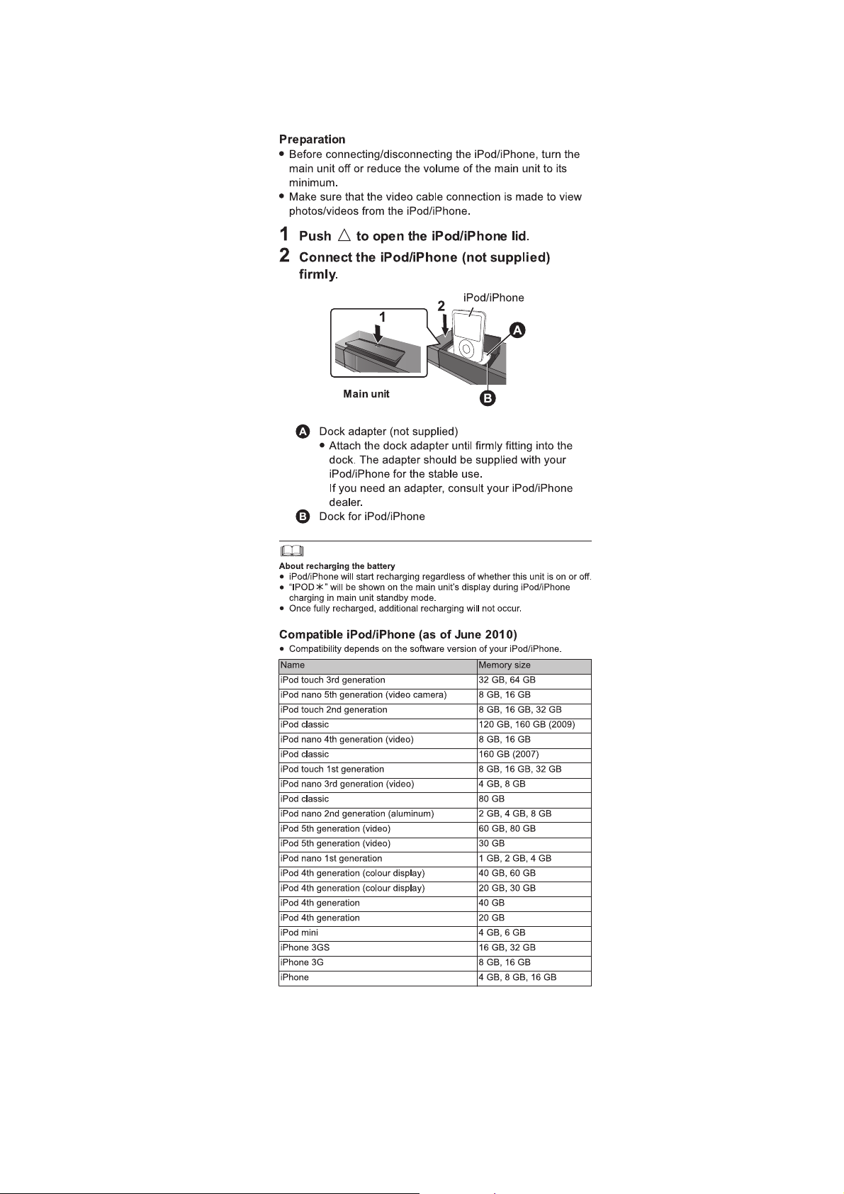
5.8. Using the iPod/iPhone
5.8.1. iPod /iPhone Connection
21
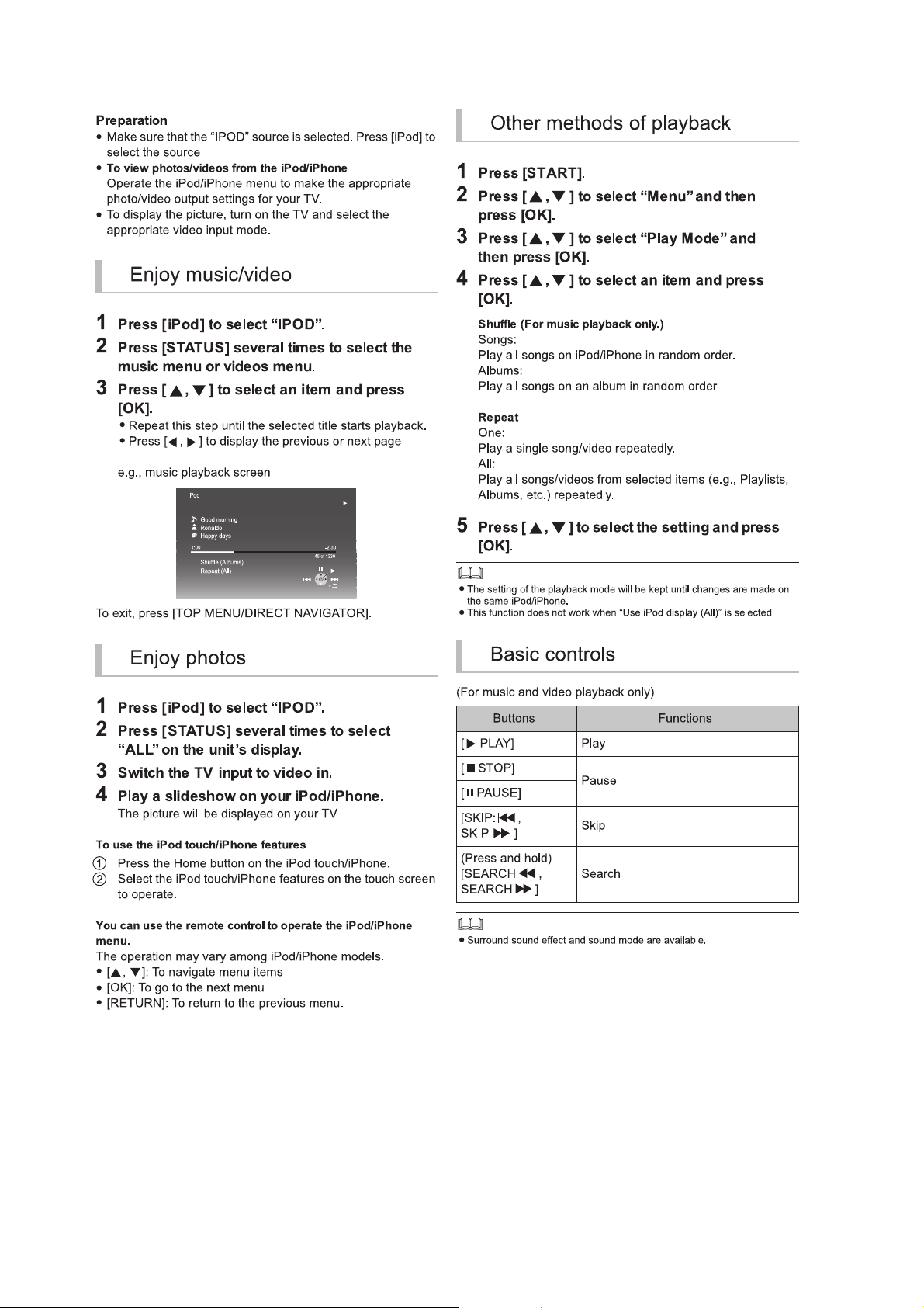
5.8.2. iPod /iPhone Playback
22
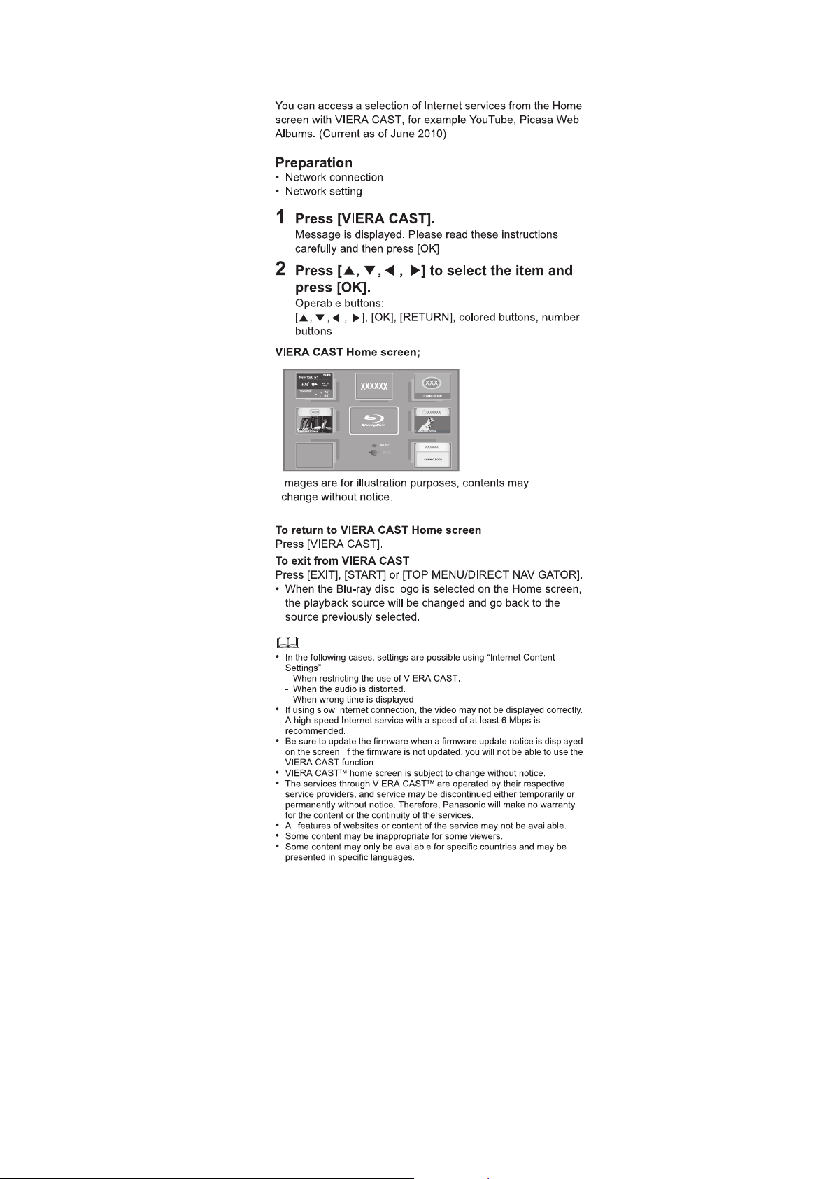
5.9. Enjoying VIERA CAST™
23
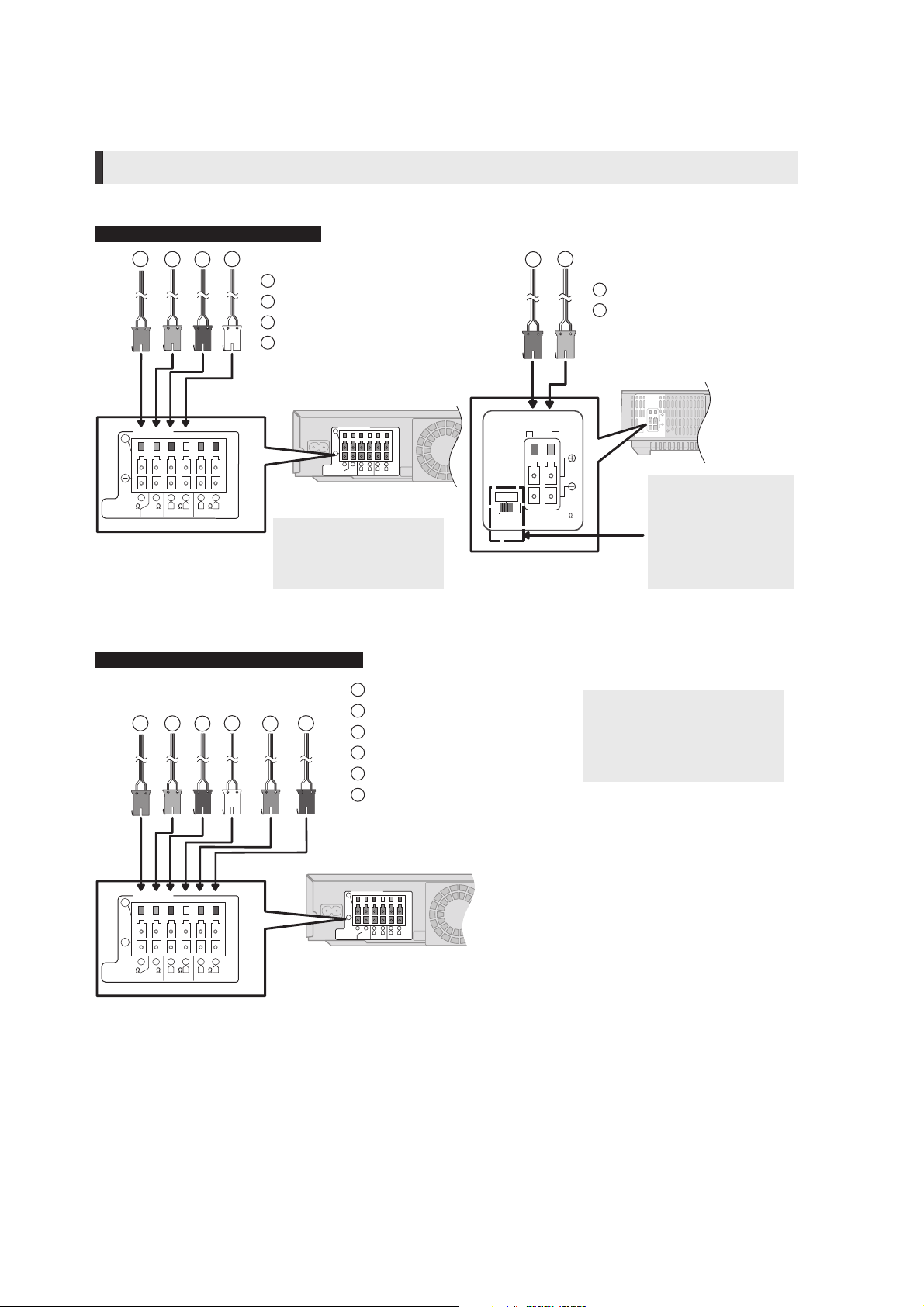
5.10. Speaker Connections
-
+
-
+
Turn off all equipment before connection and read the appropriate operating instructions.
Do not connect the AC mains lead until all other connections are complete.
Speaker cable connection
Connect to the terminals of the same colour.
BTT755 for Australia and New Zealand
65532
+
1
PURPLE Subwoofer
6
GREEN Centre speaker
2
RED Front speaker (Rch)
1
WHITE Front speaker (Lch)
3 4
SPEAKERS
ENCEINTES
LS / RB LB / RS
BLUE Surround speaker (Lch)
GREY Surround speaker (Rch)
4
Wireless system
4
2
1
R L
366
FRONT
3
R L
3
SURROUND
6
5
CENTERSUBWOOFER
Main unit
Do not connect the surround
speaker cables to the main
unit when using the wireless
system.
Except BTT755 for Australia and New Zealand
6 5 2 1
3 4
+
SURR
L
SIDERSIDE
6
PURPLE Subwoofer
5
GREEN Centre speaker
2
RED Front speaker (Rch)
1
WHITE Front speaker (Lch)
4
GREY Surround speaker (Rch)
3
BLUE Surround speaker (Lch)
SURROUND (3 - 6
)
AMBIOPHONIQUES
Surround selector
The surround selector
switch must be set in the
centre position.
When using the optional wireless
system, do not attempt to connect
any extra surround or surround
back speakers to the main unit.
4
2
3
1
6
5
R L
R L
366
3
FRONT
CENTERSUBWOOFER
SURROUND
Main unit
24
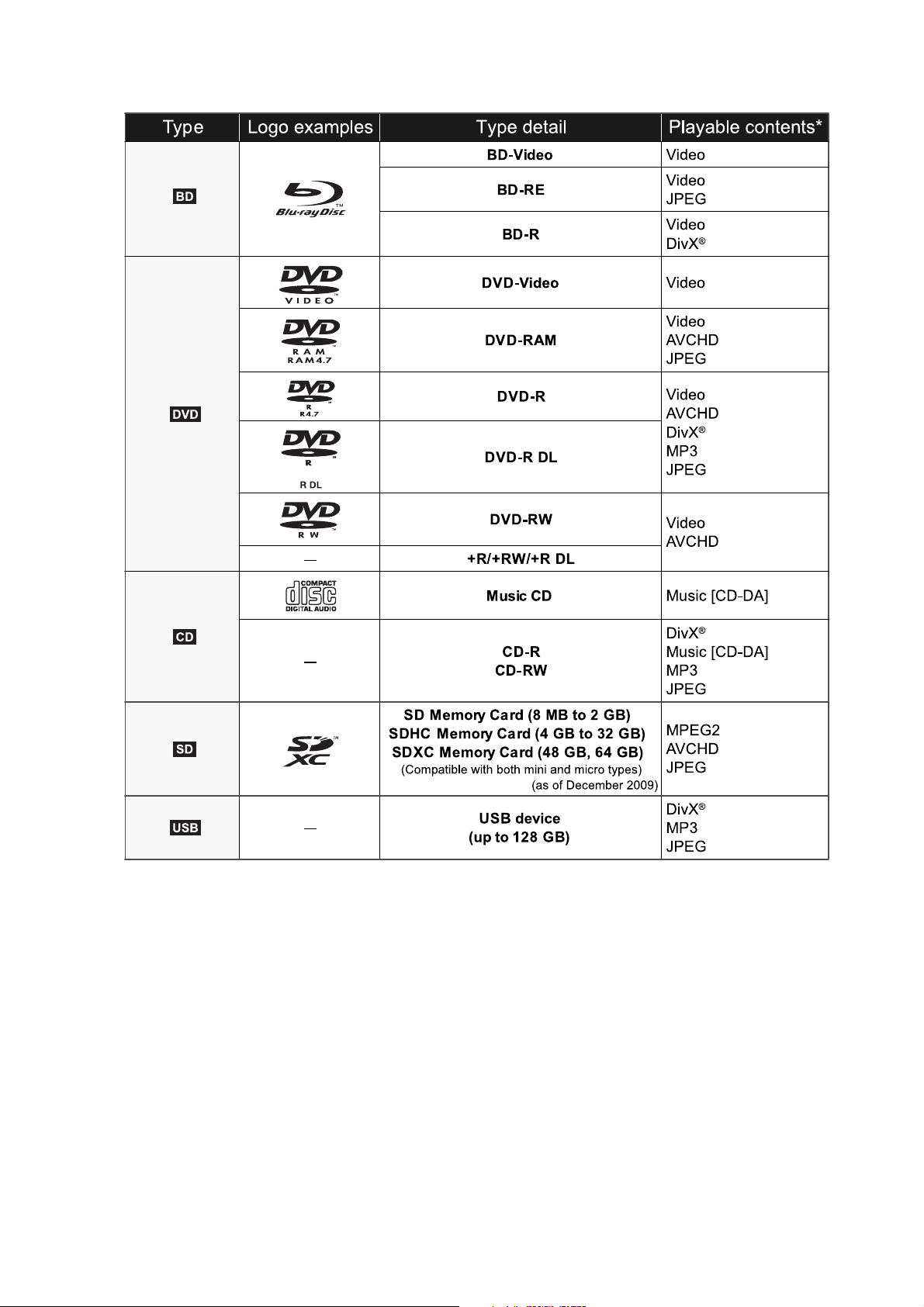
5.11. Disc/Card Playability
25
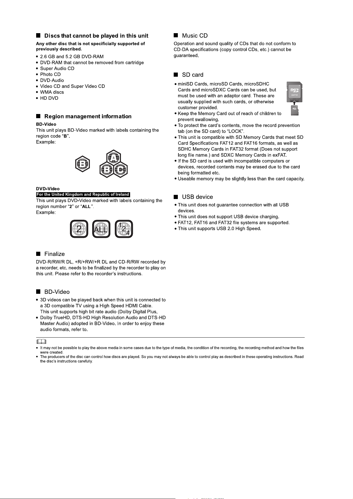
26
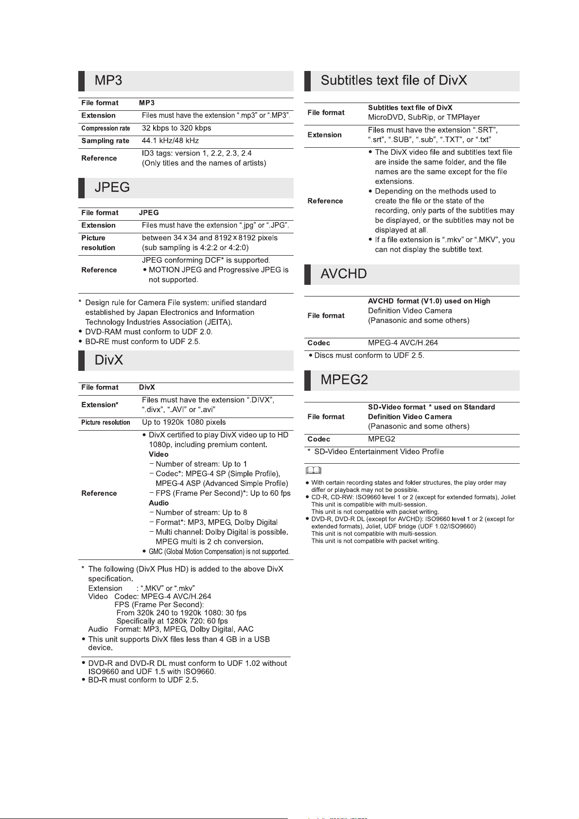
5.12. File Extension Type Support (MP3/JPEG/DivX/AVCHD/MPEG2 files)
27
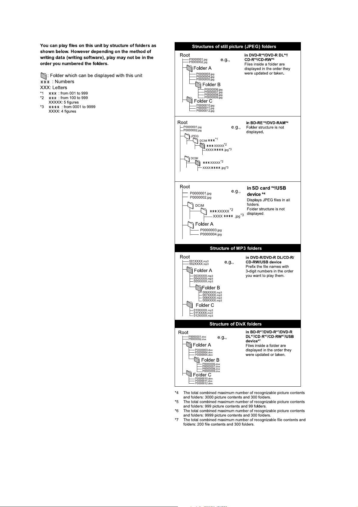
5.12.1. File Folders Structures
28
6 Operating Instructions
6.1. Removing of disc during abnomality
6.1.1. Using main unit key buttons.
6.1.1.1. When the power can be turned off.
1. Turn off the power and press & hold [SKIP FWD] button on remote and [OPEN/CLOSE] button on main unit for 5 seconds.
6.1.1.2. When the power cannot be turned off.
1. Press & hold the [POWER] button to turn off the power forcibly, then press & hold [SKIP FWD] button on remote and [OPEN/
CLOSE] button on main unit for 5 seconds.
6.1.2. When the Forcible Disc Eject cannot be done.
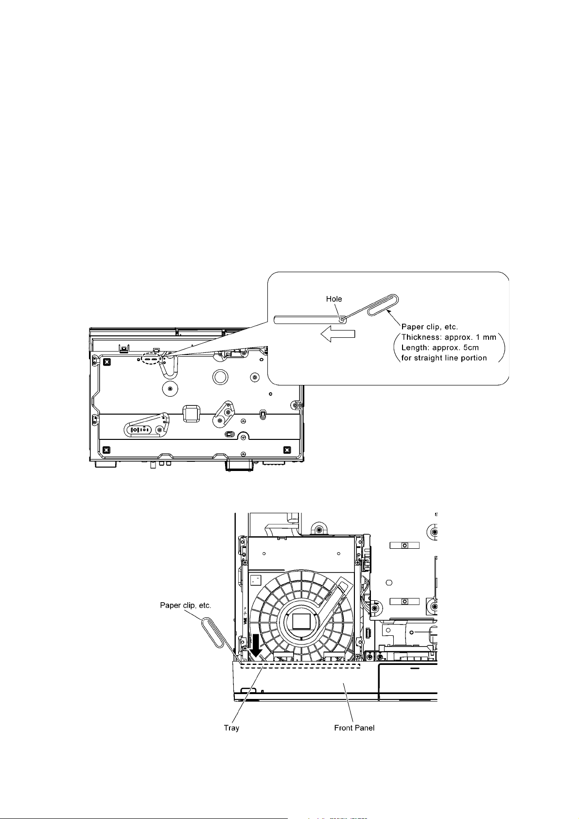
1. Turn off the power and remove AC cord.
2. Remove the Top Cabinet.
3. Put deck so that bottom can be seen.
4. Insert Paper Clip, etc. into the hole on the bottom of BD Drive and slide the eject Pin in the direction of the arrow to eject tray
slightly.
5. Pull deck upward, and push out Tray by the paper clip, etc. or minus screw driver (small).
6. Remove disc.
29
7 Self-Diagnostic and Special Mode Setting
7.1. Special Mode Table 1
Self-Diagnostic Function provides information for error to service personnel by Self-Diagnosis Display when any error has occurred.
U**, H** and F** are stored in my memory and held.
• You can check latest error code by transmitting [0] [1] of Remote Control in Service Mode.
Automatic Display on FL will be cancelled when the power is turned off or AC input i s turned off during self-diagnosis display is
ON.
Item
Mode name Description
Initialize Mode *A
Rating password
Service Mode Setting every kind of modes for servicing.
BD-ROM history cleaning < Persistent Storage> of BD-ROM standard is
Forced disc eject Removing a disc that cannot be ejected.
Forced powe r-off When the power button is not effective while
Aging Perform sequence of modes as * Aging
ll the main unit’s parameters are initialized.
1) Unit power-up
2) FL shows "Bye"
3) Unit power-down
4) Unplug & plug AC Cord
The audiovisual level setting password is ini-
tialized to Level 8.
*Details are described in 7.3.1. Service Mode
at a glance.
cleaned.
Screen display: [The player’s history data has
been cleared] is displayed for five seconds.
The tray will open and unit will shift to P-off
mode.
While Demonstration Lock is being set, this
Forced disc eject function is not accepted.
power is ON, turn off the power forcibly.
Description shown below continually.
FL display
Press & hold [VOL+], [OPEN/
-----------
INITINIT
SERV
************
Same display as before
execution.
The display before
execution leaves.
******
Display in P-off mode. P
Display following the mode. When the power is ON, press
CLOSE] follow by [POWER]
button in sequence during
power off.
Press [SKIP REV] on remote
control, follow by [PLAY] on main
unit simultaneously for five
seconds when power-on.
Press & hold [VOL+], [OPEN/
CLOSE] & [PLAY] on main
unit for 3S or more during
power off.
When power on press [STOP] on
main unit & [POWER] on remote
control.
When power is off, press [SKIP
FWD] on remote control & [OPEN/
CLOSE] key on main unit
simultaneously for 5 seconds
or more.
ress [POWER] over than 10
seconds.
[SKIP FW] on remote control,
[PLAY] & [OPEN/CLOSE] on main
set simultaneously for over 5
seconds and less than 10 seconds.
Key operation
NOTE1:
If Unit has not turned into Aging
mode by operations shown above,
execute TEST MODE once and reexecute operation shown above.
(*All the main units parameters
include tuner are initialized by
mode.)
TEST
NOTE2:
If the unit has hung-up because of
pressing keys for over 10 seconds,
once turn off the power, and re-execute this command.
*When releasing Aging mode, press
[POWER] key over 10 seconds.
30
 Loading...