

Panasonic SA-AX720 Owner’s Manual
AV ControlStereoReceiver
SA-AX920
SA-AX720
Operating Instructions
The photographs show SA-AX920.
Dear Customer
Thank you for purchasing this Technics product.
For optimum performance and safety, please read these
instructions carefully.
These operating instructions are applicable to models SA- I
AX920 and SA-AX720, however, are intended primarily for
model SA-AX920.
Tableof contents
Precautions ..................................................................................3
Supplied accessories ................................................................4
Listening caution ........................................................................4
Concerning the remote control ..............................................5
Front panel controls ..................................................................6
Equipment connections ...........................................................7
Antenna connections ..............................................................10
Speaker connections ..............................................................12
User memo:
DATE OFPURCHASE
DEALER NAME
DEALER ADDRESS
i
TELEPHONE NUMBER
I
The model number and serial number of this product can be
found on either the back or the bottom ofthe unit.
Please note them in the space provided below and keep for
future reference.
MODEL NUMBER ....................... :............................. ...................
SERIAL NUMBER ......................................................................
THE FOLLOWING APPLIES ONLY IN THE U.S.A.
AUTION:
ny unauthorized changes or modifications to this
quipment would void the user's authority to operate this
vlce.
Basic operations ...................................................................... 16
To adjust the tone quality ............................................................ 18
To adjust the sound balance ....................................................... 18
To mute the sound level .............................................................. 18
To listen through headphones ....................... _............................. 18
To compensate when the volume is low _ ......... 19
When using the VCR 2 terminals (front side)
......................................................................... 19
Listening to radio broadcasts ........................................... :.20
Sequential tuning ........................................................................ :20
Direct tuning ................................................................ 21
Preset tuning ............................................................................... 22
Enjoying sound with DOLBY PRO LO__
Setting the center mode and adjusting spe_....25
Adjusting the delay time ........................................................... .--..27
Enjoying SURROUND or 3 STEREO .................................. ._.=:28
Enjoying sound with SFC ...................................................... 29
Adjusting field of sound ............................................................... 30.
Enjoying sound with 6 channel discret_._: ........32
Making a recording ......................................................... __...'_...-33_
Recording on a tape deck............................................. 3_
Recording on a VCR .................................................................... 33
About the HELP function ....................................................... 34
Product service ........................................................................34
Troubleshooting guide ...........................................................35
Technical specifications .......................................Back cover
CAUTION
Do not place a tape deck or CD player on top ofthis unit.
Heat radiated from the top of this unit may cause damage to the
tape or CD s0ft_are.
WARNING:
TO REDUCE THE RISK OF FIRE, ELECTRIC
SHOCK OR PRODUCT DAMAGE, DO NOT
EXPOSE THIS APPLIANCE TO RAIN,
SPLASHING,DRIPPING OR MOISTURE.
CAUTION:
TO PREVE_ SHOCK MATCH WIDE
B_DE WIDE SLOT, FULLY
-- t_ _','_ _"`....
T,o P_EDUCE THE RISK OF ELECTRIC
_SH(_CK, DO NOT REMOVE SCREWS.
NO USER-SERVICEABLE PARTS
INSIDE.
REFER SERVICING TO QUALIFIED
SERVICE PERSONNEL.
The lightning flash with arrowhead symbol, within
an equilateral triangle, is intended to alert the user
to the presence of uninsulated "dangerous voltage"
within the product's enclosure that may be of
sufficient magnitude to constitute a dsk of electric
shock t'o persons.
The exclamation point within _ulfateral triangle
is intended to alert the user to the presence of
important operating and maintenance (servicing)
instructions in the literature accompanying the
appliance.
NO
Before using this unit please read these operating instructions
carefully. Take special care to follow the warnings indicated on the
unit itself as well as the safety suggestions listed below.
Afterwards keep them handy for future reference.
1. Power Source - The unit should be connected to power supply
only of the type described in the operating instructions or as
marked on the unit.
2. Polarization - If the unit is equipped with a polarized AC power
plug (a plug having one blade wider than the other), that plug
will fit into the AC outlet only one way. This is a safety
feature. If you are unable to insert the plug fully into the outlet,
try reversing the plug. If the plug should still fail to fit, contact
your electrician to replace your obsolete outlet. Do not defeat
the safety purpose ofthe polarized plug.
3. Power Cord Protection - AC power supply cords should be
muted so that they are not likely to be walked on or pinched by
items placed upon or against them. Never take hold of the plug
or cord if your hand is wet, and always grasp the plug body
when connecting or disconnecting it.
4. Nonuse Periods - When the unit is not used, tum the power
off. When left unused for a long period of time, the unit should
be unplugged from the household AC outlet.
I Environment
1.
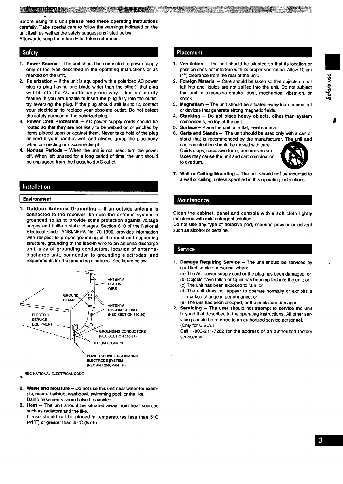
Outdoor Antenna Grounding -- If an outside antenna is
connected to the receiver, be sure the antenna system is
grounded so as to provide some protection against voltage
surges and built-up static charges. Section 810 of the National
Electrical Code, ANSI/NFPA No. 70-1990, provides information
with respect to proper grounding of the mast and supporting
structure, grounding of the lead-in wire to an antenna discharge
unit, size of grounding conductors, location of antenna-
discharge unit, connection to grounding electrodes, and
requirements for the grounding electrode. See figure below.
"__ ANTENNA
_I I""-"_ LEADIN
/ GROUND //[_3
I _ / /. _]_ OlSCHARGEUNIT
_uGIViCE_NT -_/:_ ._ (NEC SECTION 810-20)
// "pill _ y ANTENNA
I _ " GROUNDING CONDUCTORS
_IEC SECTION 810-21)
1. Ventilation - The unit should be situated so that its location or
position does not interfere with its proper ventilation. Allow 10 cm
(4") clearance from the rear of the unit.
2. Foreign Material - Care should be taken so that objects do not
fall into and liquids are not spilled into the unit. Do not subject
this unit to excessive smoke, dust, mechanical vibration, or
shock.
3. Magnetism - The unit should be Situated.away from equipment
or devices that generate strong magnetic fields.
4. Stacking -- Do not place heavy objects, other than system
components, on top of the unit.
5. Surface - Place the uniton a fiat, level surface.
6. Carts and Stands - The unitshould he used only with a cart or
stand that is recommended by the manufacturer. The unit and
cart combination should be moved with care.
Quick stops, excessive force, and uneven sur-
faces may cause the unit and cart combination
to overtum.
7. Wall or Ceiling Mounting - The unit should no( be mounted to
a wall or ceiling, unless specified in this operating instructions.
I
Clean the cabinet, panel and controls with a soft cloth lightly
moistened with mild detergent solution.
Do not use any type of abrasive pad, scouring powder or solvent
such as alcohol or benzine.
1. Damage Requiring Service - The unit should be serviced by
qualified service personnel when:
(a) The AC power supply cord or the plug has been damaged; or
(b) Objects have fallen or liquid has been spilled into the unit; or
(c) The unit has been exposed to rain; or
(d) The unit does not appear to operate normally or exhibits a
marked change in performance; or
(e) The unit has been dropped, or the enclosure damaged.
2. Servicing -- The user should not attempt to service the unit
beyond that described in the operating instructions. All other ser-
vicing should be referred to an authorized service personnel.
(Only for U.S.A.)
Call 1-800-211-7262 for the address of an authorized factory
servicenter.
a)
\ :::::::::::::::::::::
ELECTRODE _YSTEM
(NEC ART 250, PART H)
NEC-NATIONAL ELECTRICAL CODE
2. Water and Moisture - Do not use this unit near water-for exam-
ple, near a bathtub, washbowl, swimming pool, or the like.
Damp basements should also be avoided.
3. Heat -- The unit should be situated away from heat sources
such as radiators and the like.
It also should not be placed in temperatures less than 5°C
(41°F) or greater than 35°C (95°F).
/
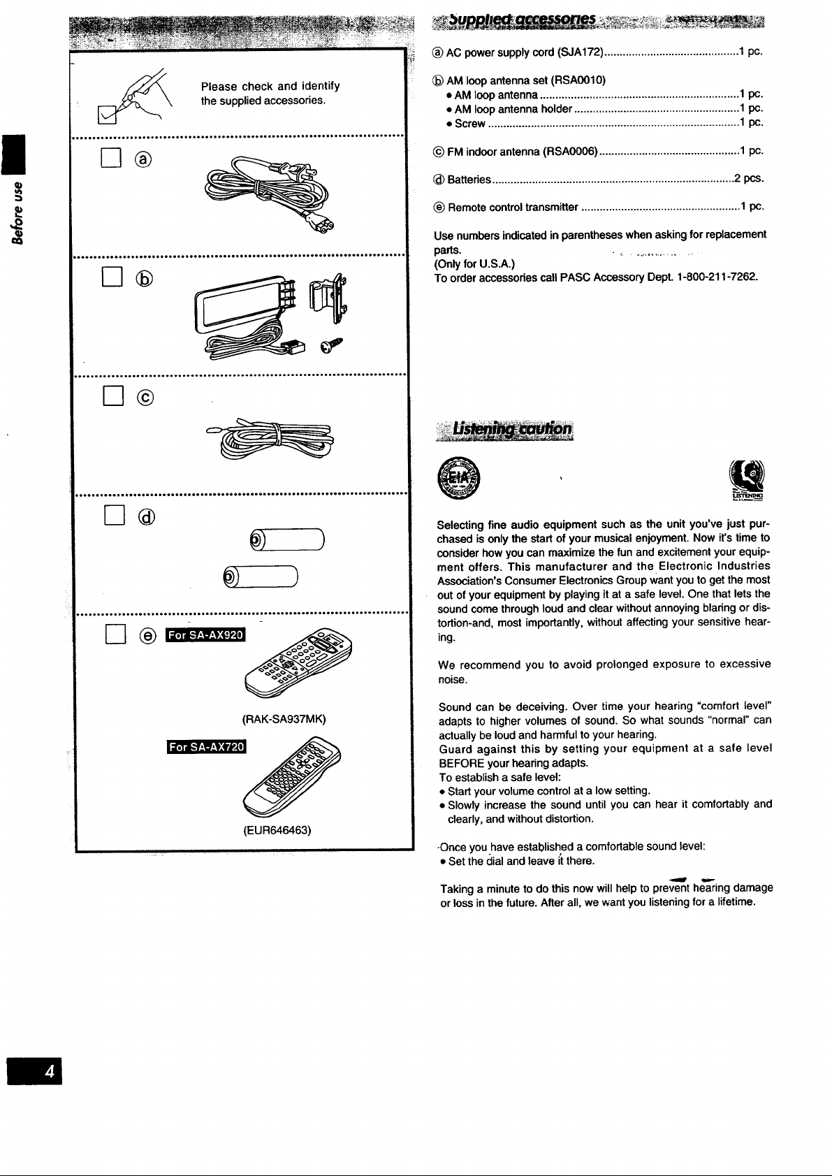
_) AC power supply cord (SJA172) ............................................ 1 pc.
(_)AM loop ar_enna set (RSA0010)
the supplied accessories.
Please check and identify
,oooHoo.ooooo...oooo...ooooo.oooo ...ooo.oooooo.ooooo.. Hoooo.. Ho-.ooo..o-ooooo
[3®
q)
oo_o_o_e_Q_j_O_eeoe_ooeeo_ooe_o_*oeoeo_o_o_0o_'
.°°°°°°°°°°°°°oo°°°o°°°°°°°°°°°°°°°°°°°.°°o°°°°°°°°°°°°°°°°°°.°°°°°°°°°°°° °°°°°o
• AM loop antenna ................................................................. 1 pc.
• AM loop antenna holder ...................................................... 1 pc.
• Screw .................................................................................. 1 pc.
_) FM indoor antenna (RSA0006) .............................................. 1 pc.
(_ Batteries ............................................................................... 2 pcs.
(_)Remote control transmitter .................................................... 1 pc.
Use numbers indicated in parentheses when asking for replacement
parts. . ,.................
(Only for U.S.A.)
To order accessories call PASC Accessory Dept. 1-800-211-7262.
D®
oooe=_______oI_oe______0ee_ee=____o_oooeeee____eoe_eo_eo__o_Deeoe______oeeoeo=o.
De
)
_________________=o_________Q_o_e______________________e___________=____________
F-I
(RAK-SA937MK)
(EUR646463)
,)
Selecting fine audio equipment such as the unit you've just pur-
chased is only the start of your musical enjoyment. Now it's time to
consider how you can maximize the fun and excitement your equip-
ment offers. This manufacturer and the Electronic Industries
Association's Consumer Electronics Group want you to get the most
out of your equipment by playing it at a safe level. One that lets the
sound come through loud and clear without annoying blaring or dis-
tortion-and, most importantly, without affecting your sensitive hear-
ing.
We recommend you to avoid prolonged exposure to excessive
noise.
Sound can be deceiving. Over time your hearing "comfort level"
adapts to higher volumes of sound. So what sounds "normal" can
actually be loud and harmful to your hearing.
Guard against this by setting your equipment at a safe level
BEFORE your hearing adapts.
To establish a safe level:
• Start your volume control at a low setting.
• Slowly increase the sound until you can hear it comfortably and
clearly, and without distortion.
-Once you have established a comfortable sound level:
• Set the dial and leave it there.
Taking a minute to do this now will help to prevent hearing damage
or loss in the future. After all, we want you listening for a lifetime.
\
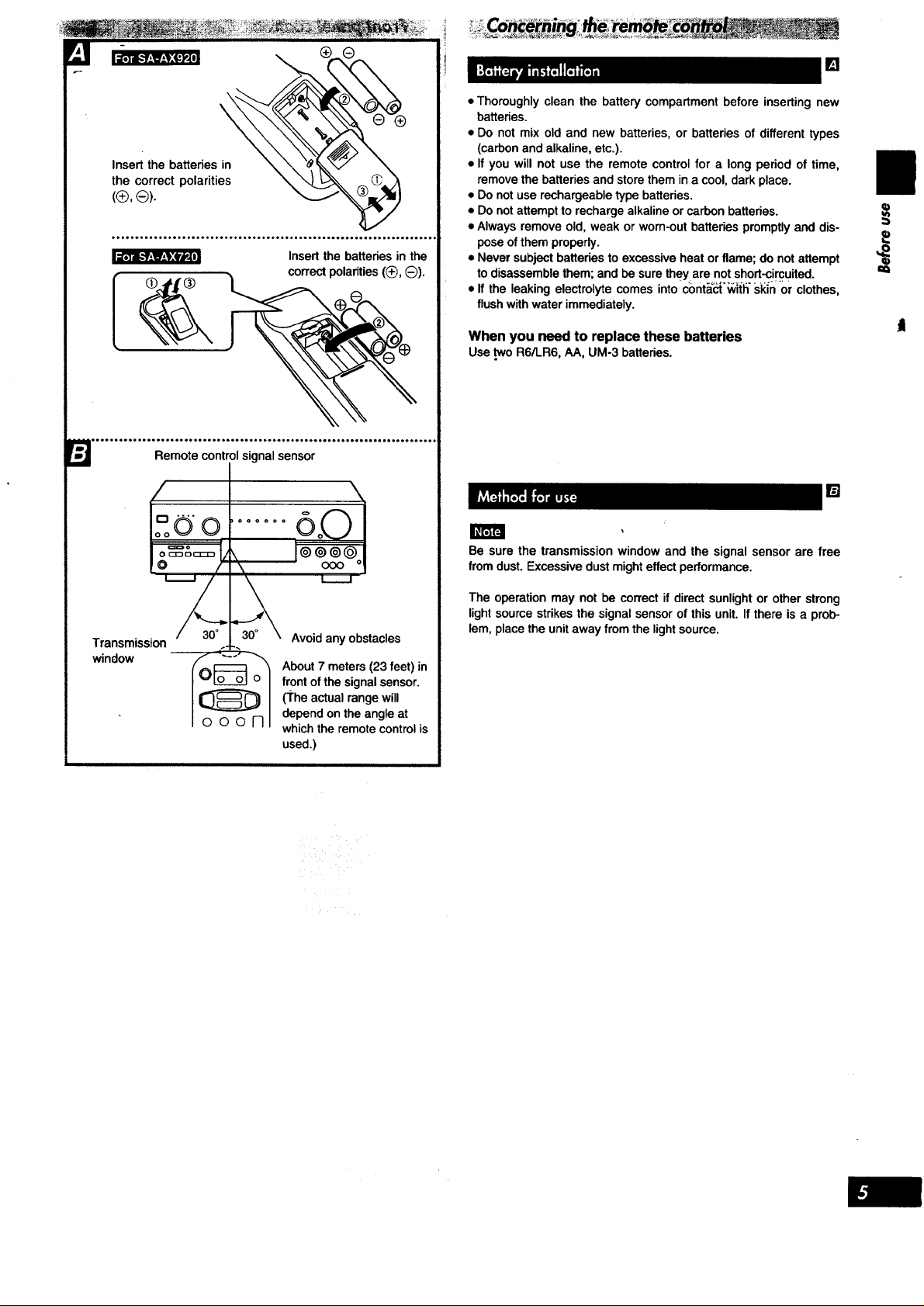
(®, ®).
oooooooooooooooooooo.,ooo°,ooo.oo.,.oo,,.ooo,..ooooooooooo,oooooo..,o0
Insert the batteries in the
correct polarities ((_, O).
o.o.oooooo,ooooooooooo,,oo.o,ooo.o,o,oooo,..ooooooooooo,ooooo,oo=o**ooooooo
r_ Remote control signal sensor
[]
• Thoroughly clean the battery compartment before inserting new
batteries.
• Do not mix old and new batteries, or batteries of different types
(carbon and alkaline, etc.).
• If you will not use the remote control for a long period of time,
remove the batteries and store them in a cool, dark place.
• Do not use rechargeable type batteries.
• Do not attempt to recharge alkaline or carbon batteries.
• Always remove old, weak or worn-out batteries promptly and dis-
pose of them properly.
• Never subject batteries to excessive heat or flame; do not attempt
to disassemble them; and be sure theY are not short-circuited.
• If the leaking electrolyte comes into c_)nt_'__ttfi "sl_in0r clothes,
flush with water immediately.
When you need to replace these batteries
UsetwoR6/LR6,AA, UM-3batteries.
==
t
[]
Transmission
window
D ....
ooo1-11
Avoid any obstacles
About 7 meters (23 feet) in
front of the signal sensor.
(1"heactual range will
depend on the angle at
which the remote control is
used.)
Be sure the transmission window and the signal sensor are free
from dust. Excessive dust might effect performance.
The operation may not be correct if direct sunlight or other strong
light source strikes the signal sensor of this unit. If there is a prob-
lem, place the unit away from the light source.

(_)Power "STANDBY _/ON" switch
(POWER, STANDBY _/ON)
Press to switch the unit from on to standby mode or vice versa.
In standby mode, the unit is still consuming a small amount of
power.
Speaker select buttons (SPEAKERS A, B)
(_) Dolby Pro Logic mode/SFC indicator
(_ Dolby Pro Logic mode/SFC selector
(_ SFC mode selector (MODE)
(_) Input indicator
(_ DVD 6ch input indicator
(_) DVD 6ch input select button (DVD 6CH INPUT)
(_ Input selector (INPUT SELECTOR)- ....
(_) Muting button (MUTING)
_) Volume control (VOLUME)
(_ Help/reset button (-HELP -RESET)
Headphones jack (PHONES)
@ Display
(_ Bass control (BASS)
Treble control (TREBLE)
VCR 2 input terminals (VCR 2)
VCR 2, TV/DSS input select button
( .,,_ VCR 2, .=_ TVIDSS)
Subwoofer level control (SUBWOOFER LEVEL)
_) Balance control (BALANCE)
Delay time adjust button (DELAY TIME)
Center mode select button (CENTER MODE)
Loudness ON/OFF button (LOUDNESS)
_)Tuning buttons (TUNING)
Radio station presetting button (PRESET)
Band select button (BAND)
_) FM mode select button (FM MODE)
Memory button (MEMORY)
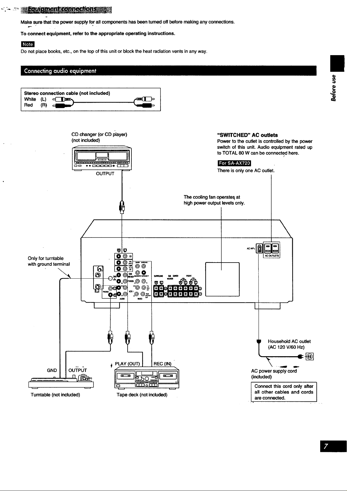
Make sure that the power supply for all components has been turned off before making any connections.
To connect equipment, refer to the appropriate operating instructions.
IIIrRF3
Do not place books, etc., on the top of this unit or block the heat radiation vents in any way.
Stereo connection cable (not included)
White (L)
Red (R)
Only for turntable
with ground terminal
CD changer(orCD player)
(notincluded)
OUTPUT
"SWITCHED" AC outlets
Power to the outlet is controlled by the power
switch of this unit. Audio equipment rated up
to TOTAL 80 W can be connected here.
I'a'_i,k'Jr.,_-,,:_l
There is only one AC outlet.
The cooling fan operate,_ at
high power output levels only.
i
I I
GND I OU]:PLJT
oll n_
Turntable (notincluded)
PLAY (OU--_ :IEC (IN)
Tape deck (not included)
Household AC outlet
(AC 120 V/60 Hz)
=@
AC power supply cord
(included)
Connect this cord only after I
all other cables and cords
..b
Iare connected.
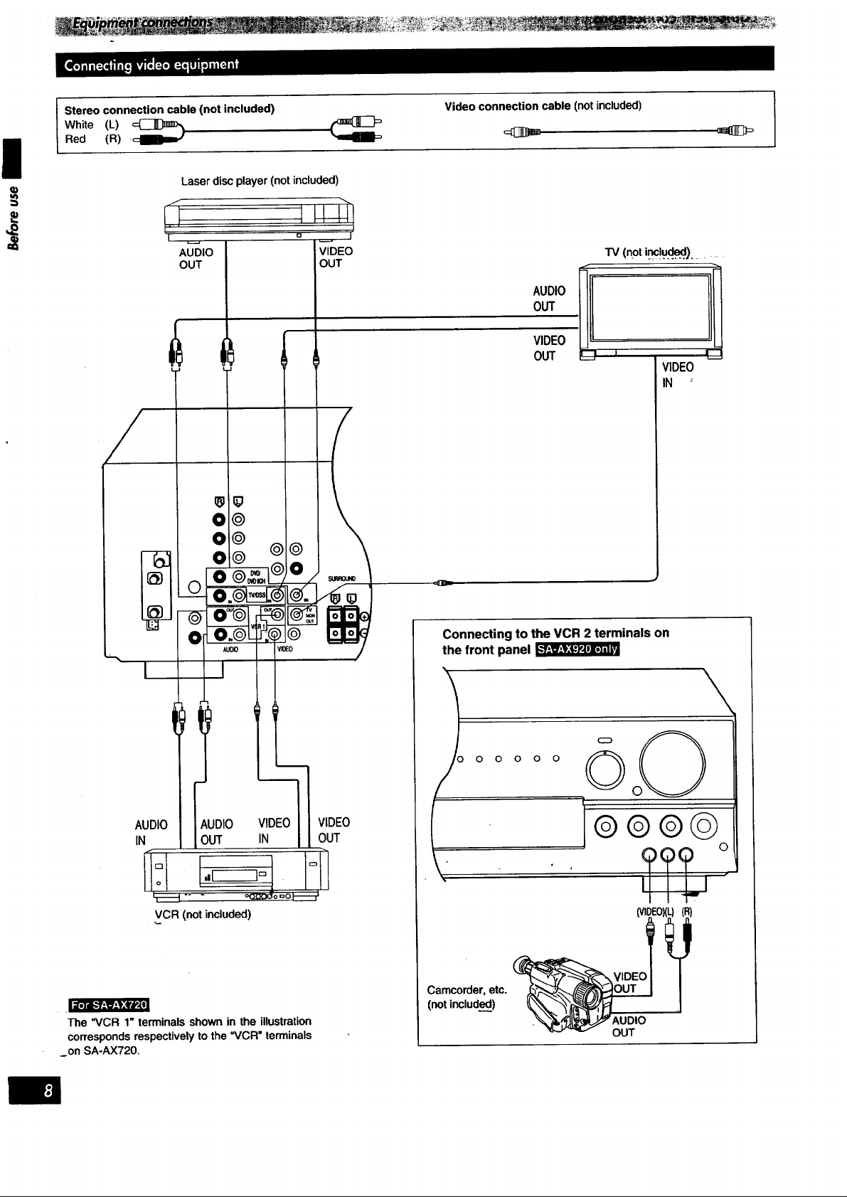
Stereo connection cable (not included)
White (L) _
Red (R) •
Laser disc player (not included)
f
P
,I
I
AUDIO
OUT
Video connection cable (not included)
TV (not ir_c!u..d_l)......
AUDIO
OUT
VIDEO
OUT
VIDEO
IN '
AUDIO
IN
AUDIO VIDEO
OUT IN
[.I-----I=
VCR (not included)
The "VCR 1" terminals shown in the illustration
corresponds respectively to the "VCR" terminals
on SA-AX720.
VIDEO
OUT
Connecting to the VCR 2 terminals on
the front panel
O O O O
° Q
(
(R)
Camcorder, etc.
(not included)
AUDIO
OUT
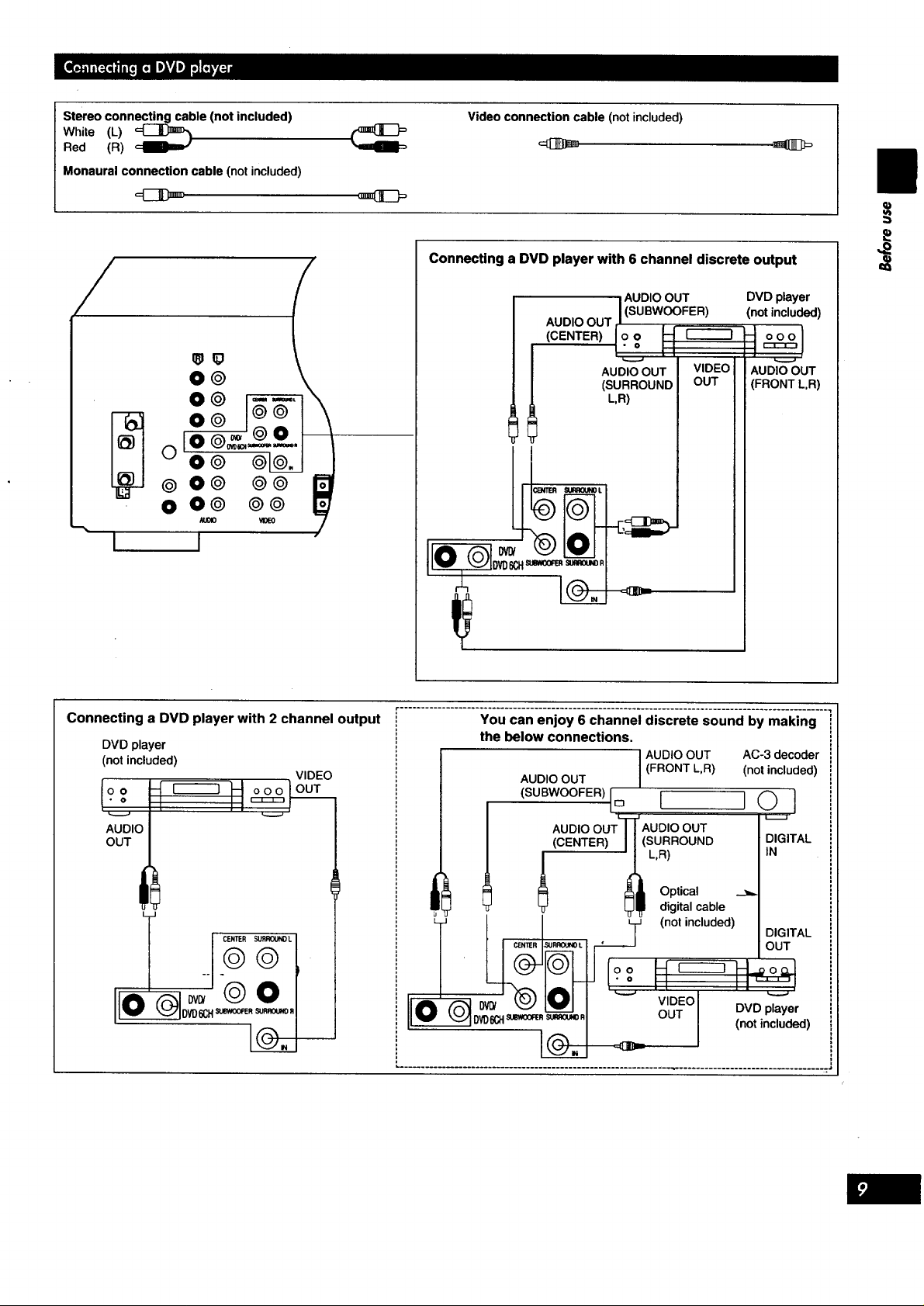
Stereoconnectingcable(notincluded)
White(L)_
Red (R)
Monaural connection cable (not included)
Video connection cable (not included)
I
Connecting a DVD player with 6 channel discrete output
/
O@
O@
@
0 O@ @@
i€.lOl0 _IT¢0
I I
Connecting a DVD player with 2 channel output
DVD player
(not included)
VIDEO
ooo
AUDIO
OUT
t
r ......................................................................................................
You can enjoy 6 channel discrete sound by making
the below connections,
AUDIO OUT
(SUBWOOFER) o
AUDIO OUT t
AUDIO OUT VIDEO AUDIO OUT
(SURROUND OUT (FRONT L,R)
L,R)
(CENTER) /
I AUDIO OUT DVD player
I(SUBWOOFER) (not included)
t2 I-I
(FRONT L,R) (not included)
AUDIO OUT AC-3 decoder
i
AUDIO OUT
(SURROUND DIGITAL
L,R) IN
D _ n
_UD,OOUq
I_ Optical
digital cable
L[ (not included)
oo kt r----_ I-L._._
VlDEOI I I_ ,.__..,
OUT I DVD player
I
L.......................................................... _ ................................. ":'
DIGITAL
OUT
(not included)
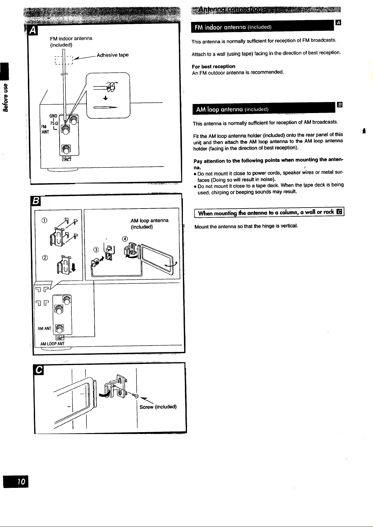
FM indoor antenna
(included)
[]
This antenna is normally sufficient for reception of FM broadcasts.
Attach to a wall (using tape) facing in the direction of best reception.
For best reception
An FM outdoor antenna is recommended.
[]
ThisantennaisnormallysufficientforreceptionofAMbroadcasts,
Fit the AM loop antenna holder (included) onto the rear panel of this
unit and then attach the AM loop antenna to the AM loop antenna
holder (facing in the direction of best reception).
Pay attention to the following points when mounting the anten-
na.
• Do not mount it close to power cords, speaker wires or metal sur-
faces (Doing so will result in noise).
• Do not mount itclose to a tape deck. When the t_pe deck isbeing
used, chirping or beeping sounds may result.
AMANT
AMLOOPANT
AMloopantenna
(included)
®
I When mounting the antenna to a column, a wall or rack [] I
Mount theantennaso thatthe hingeis vertical.
Screw (included)
II .....
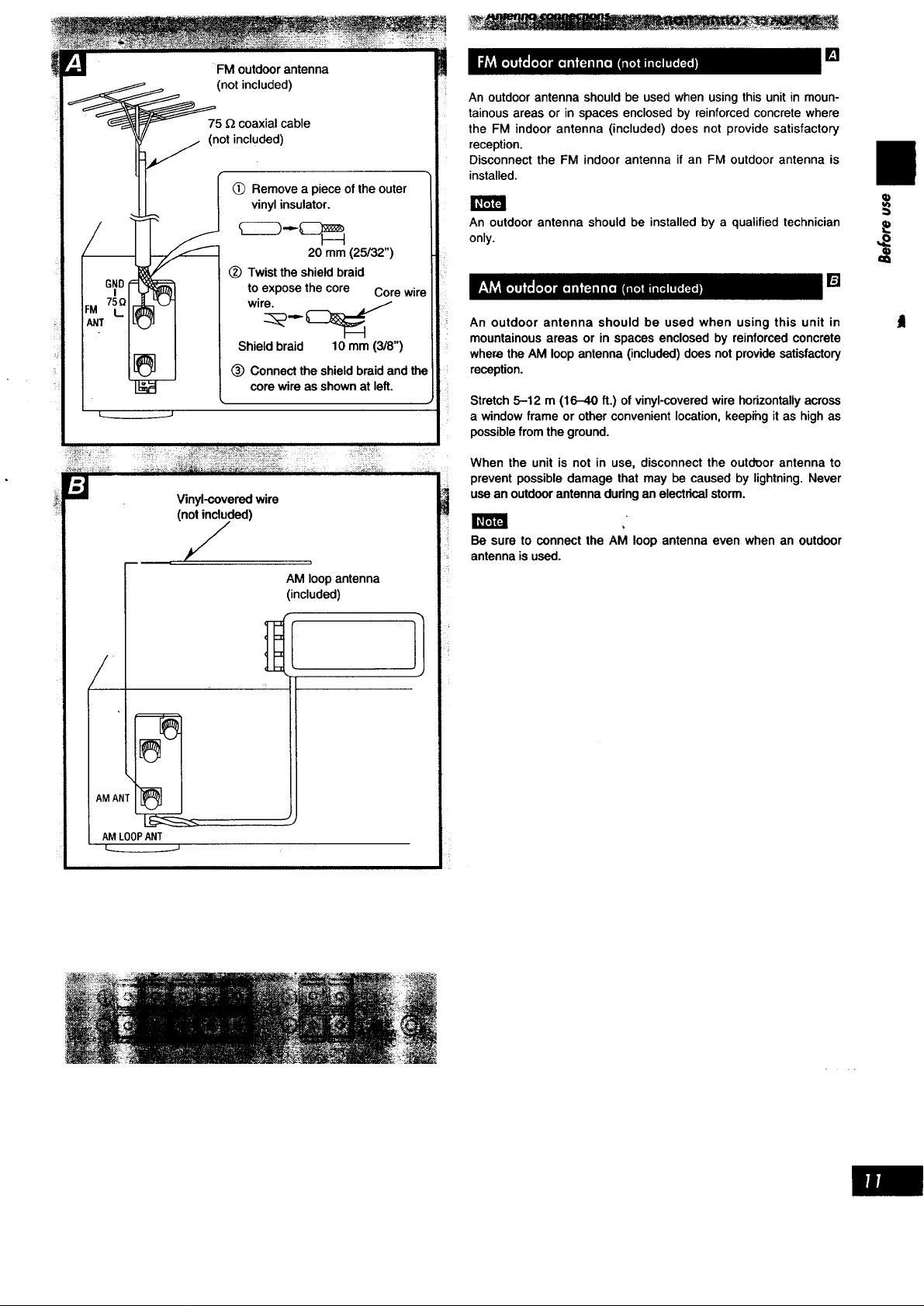
FM outdoor antenna
(not included)
75 _ coaxial cable
(not included)
(_) Remove a piece of the outer
vinyl insulator.
(_) Twist the shield braid
to expose the core
wire.
Shield braid 10 mm (3/8")
(_) Connect the shield braid and the
core wire as shown at left.
Vinyl-covered wire
(not included)
J ,
AM loop antenna
(included)
[]
An outdoor antenna should be used when using this unit in moun-
tainous areas or in spaces enclosed by reinforced concrete where
the FM indoor antenna (included) does not provide satisfactory
reception.
Disconnect the FM indoor antenna if an FM outdoor antenna is
installed.
An outdoor antenna should be installed by a qualified technician
only.
20 mm (25/a2")
[]
An outdoor antenna should be used when using this unit in
mountainousareas or in spaces enclosedby reinforcedconcrete
wherethe AM loopantenna(included)doesnot providesatisfactory
reception.
Stretch 5-12 m (16-40 ft.) of vinyl-covered wire horizontally across
a window frame or other convenient location, keepihg it as high as
possible from the ground.
When the unit is not in use, disconnect the outdeor antenna to
prevent possible damage that may be caused by lightning. Never
use an outdoor antenna dudng an electrical storm.
Be sure to connect the AM loop antenna even when an outdoor
antenna is used.
.
AM AI_
AMLOOPANT
 Loading...