

Page 1
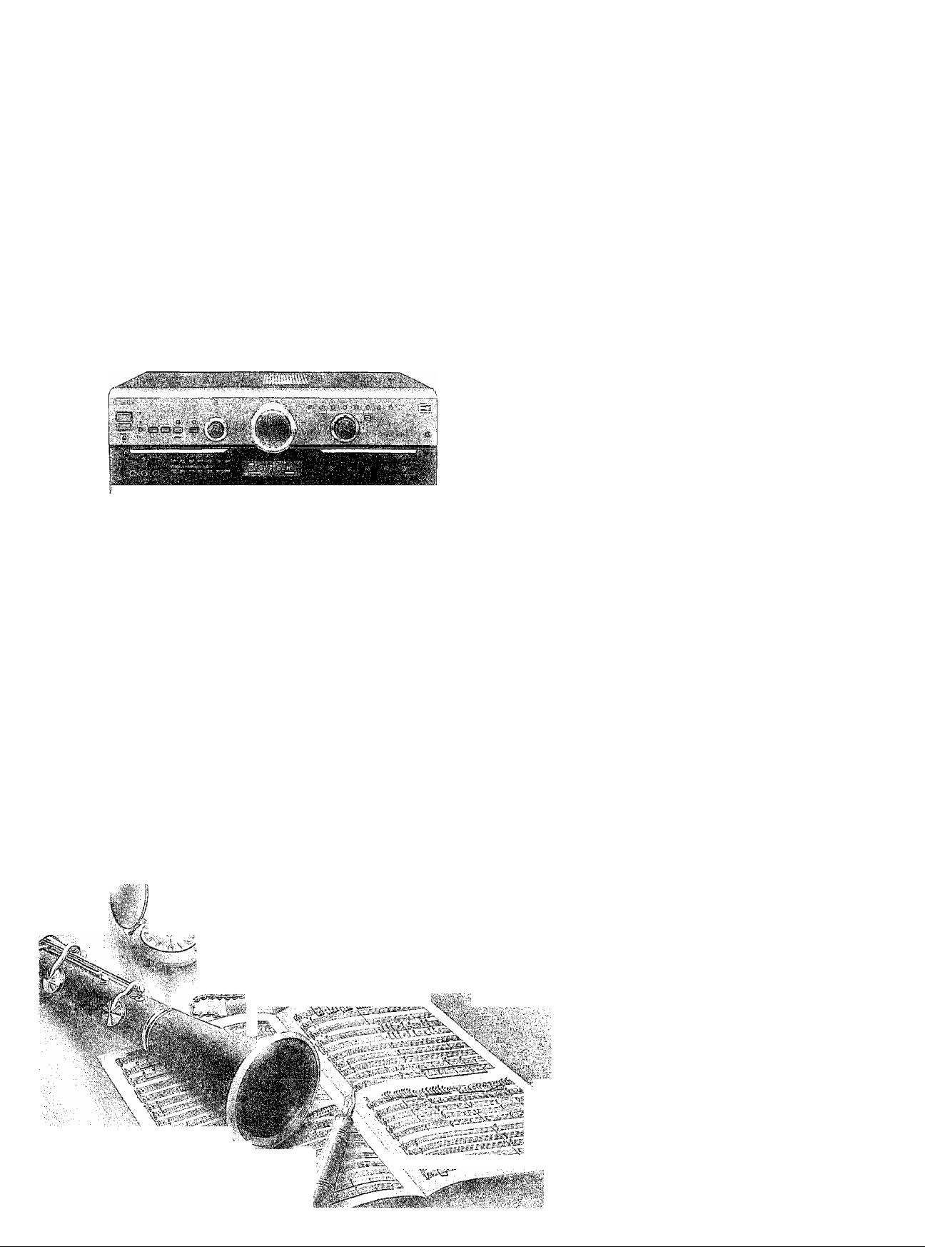
AV Control Stereo Receiver
SA-AX6
Operating Instructions
a m
^ <;fi
Technic^
GC GN
V', /rrr'sViV:;. y ;; , -...,■■ ■-... .. 'v^' y'
iS'iii y; y :.i ■'.■■'.■ ■: y ■■ ’■ -■ ■.'■■:■'■ ■ ■■ ■. / ■ ■ ;
Before connecting, operating or adjusting this
product, please read these instructions completeiy.
Please save this manual.
RQT4465-L
Page 2
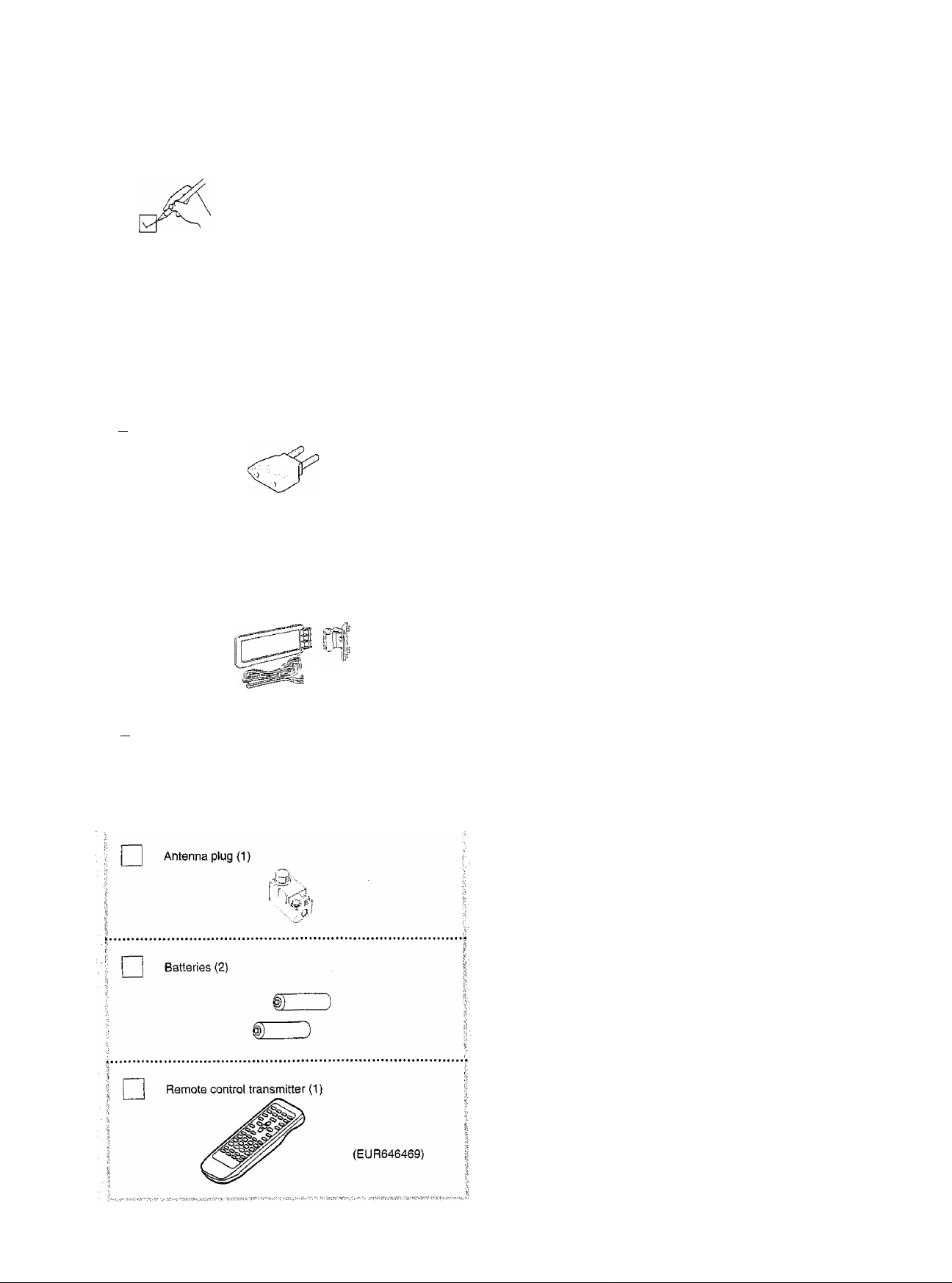
Supplied accessories
Please check and identity
the supplied accessories.
Dear Customer
Thank you for purchasing this product.
For optimum performance and safety, piease read
these instructions carefully.
(For areas except Australia and N.Z.)
AC power supply cord (t)
{For Australia and N.Z.)
I I Power plug adaptor (1 )
(For areas except Australia and N.Z.)
AM loop antenna set
□
« AM loop antenna (1)
a AM loop antenna holder (1)
a Screw (1)
[ I FM indoor antenna (1 )
(For others)
CAUTIOM;
The AC voltage is different according to the
area.
Be sure to set the proper voltage in your area
before use.
(For details, please refer to the page 9.)
Table of contents
Suggestions for safety
Concerning the remote control
Front panel controls.......................................................5
Equipment connections
Antenna connections
Speaker connections
Basic operations
To open the front cover..............................................................18
To adjust the tone quality...........................................................18
To adjust the sound balance......................................................18
To mute the sound level.............................................................18
To listen through headphones
To compensate when the volume is low..'.
When using the VCR 2 terminals (front side)
To adjust the high and low balance of the front speakers
To adjust the output range of the subwoofer
Listening to radio broadcasts
Sequential tuning
Direct tuning
Preset tuning..............................................................................22
..............................................................................
Enjoying sound with DOLBY PRO LOGIC
Setting the center mode and adjusting speaker output level
Adjusting the delay time.............................................................27
Enjoying SURROUND or 3 STEREO
Enjoying sound with SFC.............................................29
Adjusting field of sound..............................................................30
Enjoying sound with 6 channel discrete
Making a recording
Recording on a tape deck..........................................................33
Recording on a VCR..............................................................33
Timer function
..............................................................
...................................................
......................................
.................................................
...................................................
...................................................
..........................................................
...................................................
................................
............................
...........
.............................
.......................................
.......................................................................
..................
......
........................................
......................
......................................................
10
12
16
25
32
33
34
3
4
6
18
19
19
19
19
20
20
21
25
28
Troubleshooting guide
Technical specifications
.................................................
..................................
Back cover
35
Maintenance....................................................Back cover
Page 3
Suggestions hr safety
..
.. ... ... . ... ... . ... ... ... . ..
■'
.. .. ... ... ... ... .
Avoid placing the unit in areas of:
« direct sunlight
• high temperature
• high humidity
® excessive vibration
® uneven surfaces (Place the unit on a fiat level surface.)
Such conditions might damage the cabinet and/or other component
parts and thereby shorten the unit’s service life.
9 It is very dangerous to use an AC power source of high voltage
such as for an air conditioner.
A fire might be caused by such a connection.
« A DC power source can not be used.
Be sure to check the power source carefully, especially if on a
ship or other place where DC is used.
* Avoid cuts, scratches or poor connection of the AC power cord, as
this may result in fire or electric shock.
Excessive bending, pulling or slicing of the cord should also be
avoided.
» Do not pull on the cord when you are disconnecting the power, as
this could cause an electric shock. Grasp the plug firmly when you
disconnect the power supply.
o Never touch the plug with wet hands or a serious electric shock
could result.
• Never attempt to repair, disassemble or reconstruct the unit if
there seems to be a problem.
A serious electric shock could result if you ignore this precaution
ary measure.
© if a problem occurs during operation (the sound is interrupted,
indicators fail to light up, smoke is detected, etc.) contact your
dealer or Authorized Service Center immediately,
o Disconnect the power supply if the unit will not be used for a long
time. Otherwise the operation life could be shortened.
CAUTION!
DO..NOT INSTALL OR PLACE THIS UNIT IN A BOOKCASE,
BUILT IN CABINET OR IN ANOTHER CONFINED SPACE IN
ORDER TO KEEP WELL VENTILATED CONDITION. ENSURE
THAT CURTAINS AND ANY OTHER MATERIALS DO NOT
OBSTRUCT THE VENTILATION CONDITION TO PREVENT
RISK OF ELECTRIC SHOCK OR FIRE HAZARD DUE TO
OVERHEATING.
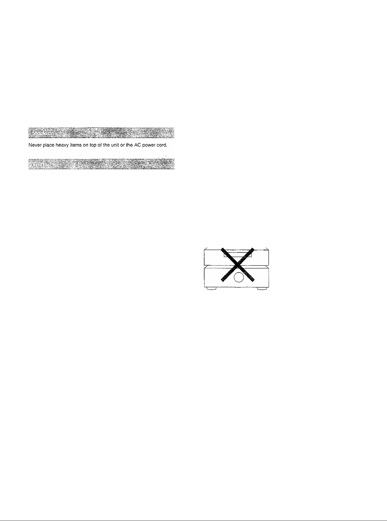
CAUTION
Do not place a tape deck or CD player on top of this unit.
Heat radiated from the top of this unit may cause damage to the
tape or CD software.
NO
• Ensure that no foreign objects, such as needles, coins, screw
drivers etc., accidentally fall into the unit.
Otherwise, a serious electric shock or malfunction could occur.
• Be extremely careful about spilling water or liquid on/into the unit,
as a fire or electric shock could occur.
(Disconnect the power plug and contact your dealer immediately if
this occurs.)
• Avoid spraying insecticides onto the unit as they contain flamma
ble gases which can be ignited.
• Insecticides, alcohol, paint thinner and similar chemicals should
never be used to clean the unit as they can cause flaking or
cloudiness to the cabinet finish.
Page 4
I
<u
wi
s
1
Concerning fhe remote control
mm
o Thoroughly clean the battery compartment before inserting new
batteries.
® Do not mix o!d and new batteries, or batteries of different types
(carbon and alkaline, etc.).
® If you will not use the remote control for a long period of time,
remove the batteries and store them in a cool, dark place.
® Do not use rechargeable type batteries.
© Do not attempt to recharge alkaline or carbon batteries.
9 Always remove old, weak or worn-out batteries promptly and dis
pose of them properly.
9 Never subject batteries to excessive heat or flame; do not attempt
to disassemble them; and be sure they are not short-circuited.
® If the leaking electrolyte comes into contact with skin or clothes,
flush with water immediately.
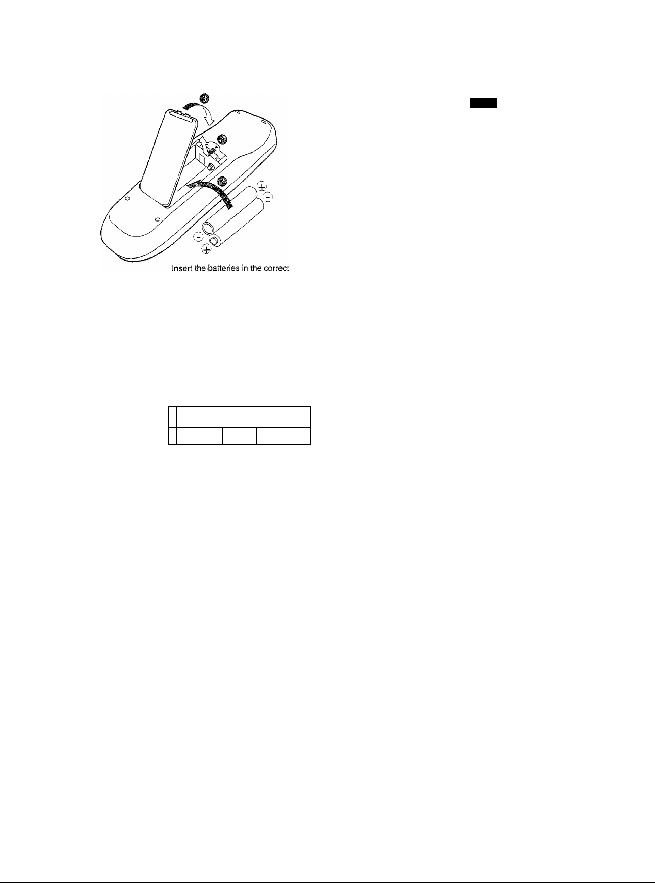
Remote control signal sensor
Transmission
window
polarities (®, ©).
^0 ooa ó(^ ( 1
Ok OGQOOCO
SO® 00000=51 1
oooo
oooo
‘o CD O
o Q o
oao
o O o
oo o
When you need to replace these batteries
Use two R6/LR6, AA, UM-3 batteries.
m
Be sure the transmission window and the signal sensor are free
from dust. Excessive dust might effect performance.
The operation may not be correct if direct sunlight or other strong
tight source strikes the signal sensor of this unit. If there is a prob
lem, place the unit away from the light source.
o
oooo©
Avoid any obstacles
About 7 meters in front
of the signal sensor.
(The actual range will
depend on the angle at
which the remote control
is used.)
Page 5
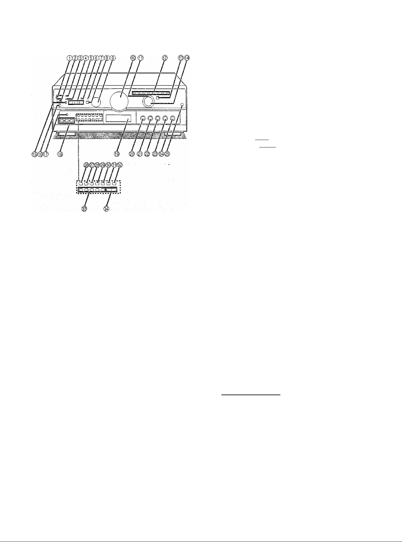
Front panel controls
'© Power “STANDBY cb /ON” switch
(POWER, STANDBY 6/ON)
Press to switch the unit from on to standby mode or vice versa.
In standby mode, the unit is stili consuming a small amount of
power.
(D Remote control signal sensor
©“STANDBY” indicator (STANDBY)
When the unit is connected to the AC mains supply, this indica
tor lights up in standby mode and goes out when the unit is
turned on.
® Wake timer indicator (WAKE)
® Speaker select buttons
(SPEAKERS A, B, ilSMgjin
® Bi-amp indicator (BS-AMP)
(©Subwoofer adaptive controi indicator
(SUBWOOFER ADAPTIVE CONTROL)
® Subwoofer adaptive controi ON/OFF button
©Subwoofer level controi (SUBWOOFER LEVEL)
©Volume controi (VOLUME)
©DVD 6ch input indicator
(©Input Indicators
©DVD 5ch input select button (DVD 6CH INPUT)
© Input selector (INPUT SELECTOR)
©Timer setting button (TIMER)
©Headphones jack (PHONES)
©TV/VCR 2 input select button (TV, VCR 2)
© VCR 2 input terminals (VCR 2)
© Display
© Bass control (BASS)
©Treble control (TREBLE)
©Balance control (BALANCE)
©Bi-amp balance control (BI-AMP BALANCE)
©Subwoofer low pass filter control
(SUBWOOFER LOW PASS FILTER)
© Front cover open button (PUSH OPEN)
© DOLBY PRO LOGiC/SFC OFF/ON button
(OFF/ON)
©DOLBY PRO LOGIC mode select button
(□□ PRO LOGIC)
© Delay time adjust button (DELAY TIME)
©Center mode select button (CENTER MODE)
© Band/FM mode select button
(-BAND, -FM MODE)
©Radio station presetting button (PRESET)
© Memory button (MEMORY)
© Sound field control buttons
___________________
(SFC
©Tuning buttons (TUNING)
Page 6
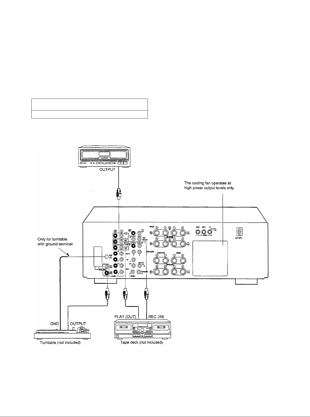
Equipment connections
Make sure that the power supply for all components has been turned off before making any connections.
Refer to the operating instructions of the equipment to be connected.
Do not place books, etc., on the top of this unit or block the heat radiation vents in any way.
I
0
Vi
D
1
s*
<u
ea
Stereo connection cabie (not included)
White (L) <3Dmrox
Red (R) cjli^ xnBnaiiai^
CD changer (or CD player)
(not included)
-■
....
!. -.. ■ ....i'. -................; 1. . ■ .'.
...
Page 7
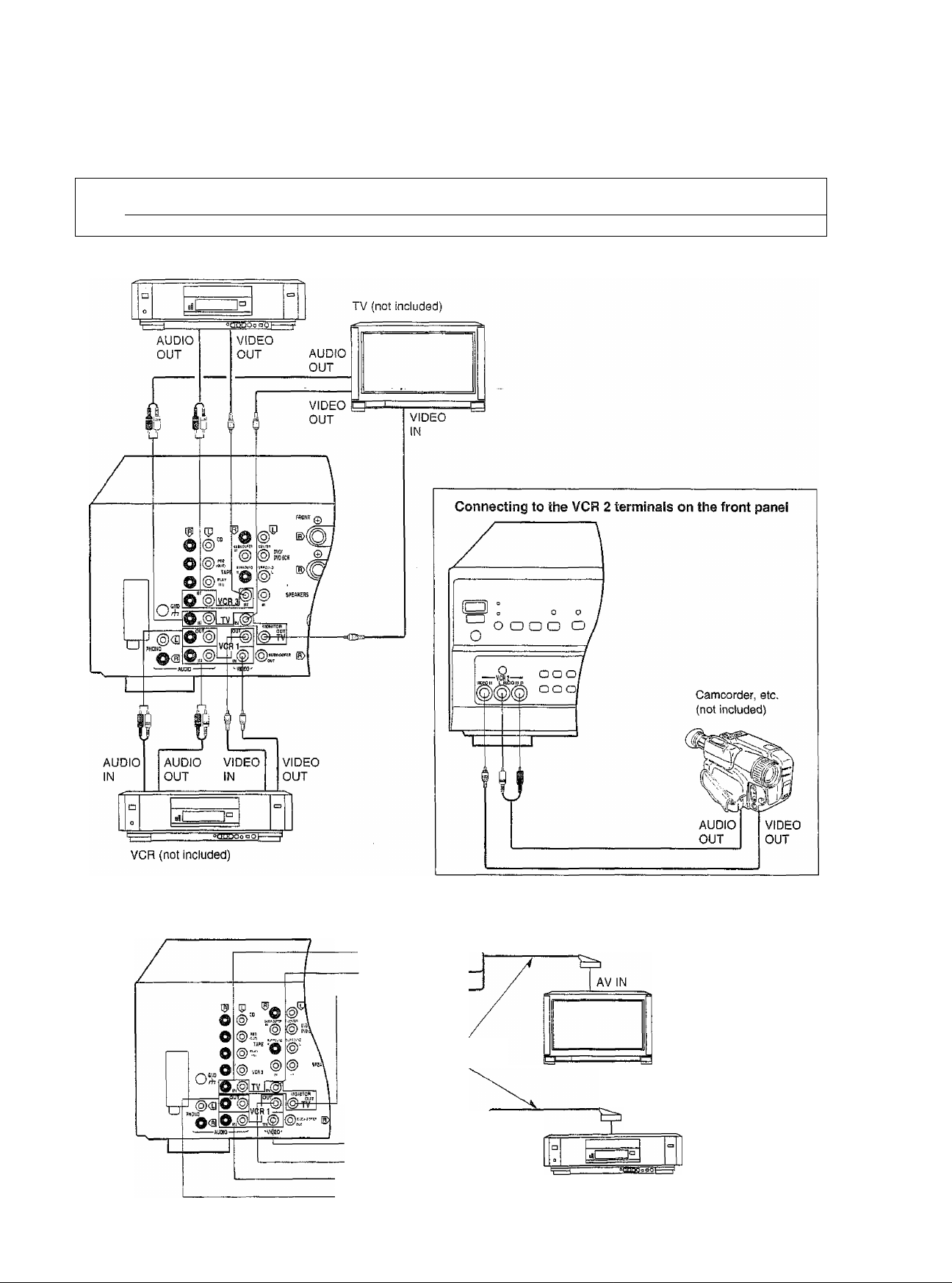
Stereo connection cable (not included)
White (L) ^-«01
Red (H)^aiiiin^
VCR (for playback only) (not included)
Video connection cable (not included)
(AUDIO OUT)
^ (VIDEO OUT)
-----
<3= (VIDEO IN)_
(VIDEO OUT).
^ (VIDEO IN) —
r^(AUDIO OUT)
C^PiAUDIO IN)
TV (not included)
21 pin scart cables
(not included)
AV IN
VCR (not included)
------------
---------
Page 8
Equipment connections
Stereo connection cable (not included)
White (L)
Red (R)
Monaural connection cable (not included)
<2Binn
--------------
^-----------------------
------
mal b
1 i®0 é
Sir®©-'
O in'“ 'O ®' I
Q-@„, f|@J”—
awj
O
ff-
®,„® W ,K@
our^ OUT-—s V OUT
©
CT
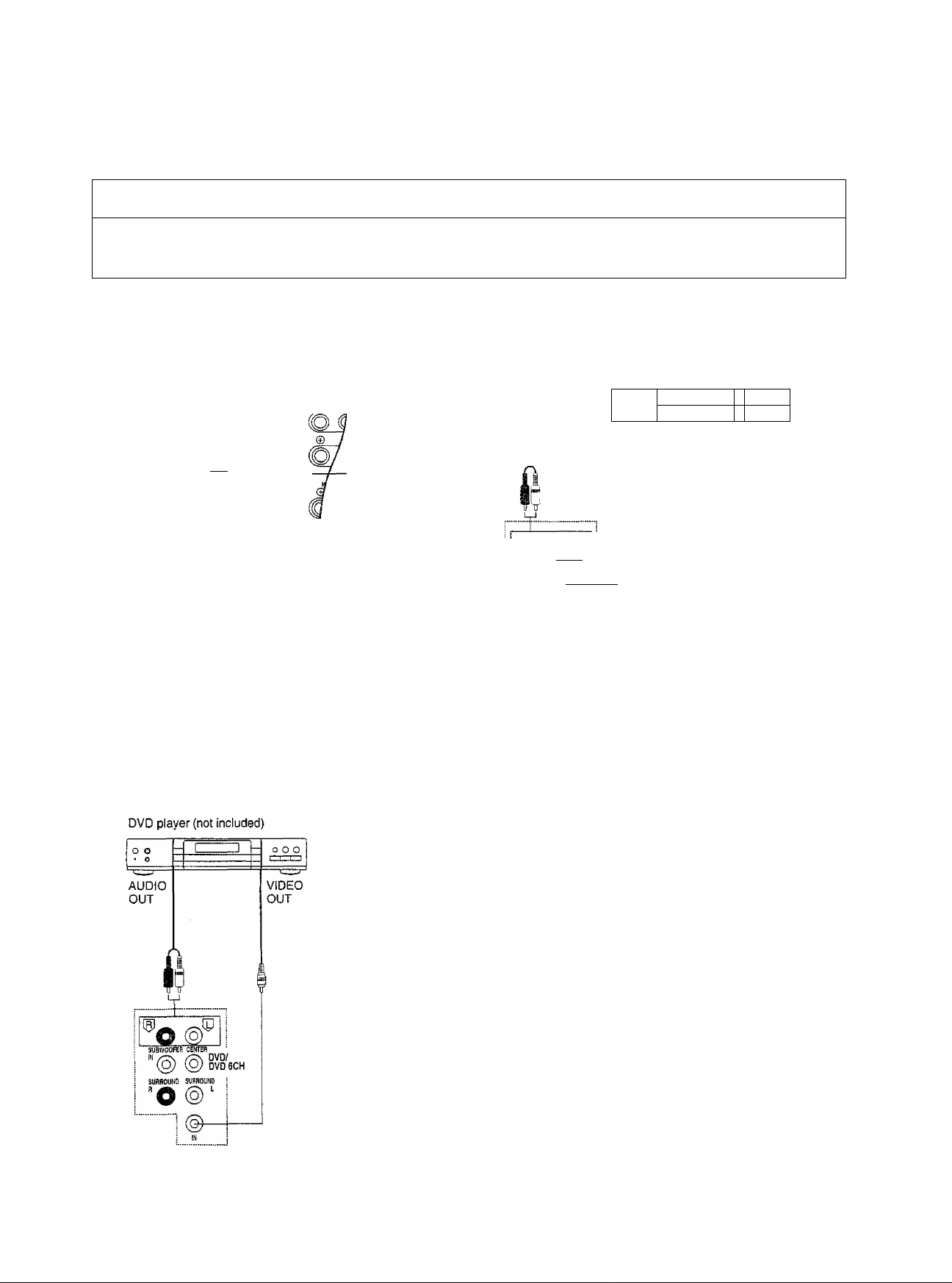
If you want to connect a DVD player with DISCRETE 6CH
output using only 2 channels, make the connection through
the DVD player’s MIXED AUDIO OUT terminals and this
unit’s DVD/DVD 6CH L and R terminals.
Do not connect any cables to this unit’s DVD/DVD 6CH
CENTER, SUBWOOFER IN, or SURROUND L and R ter
minals.
I © @ @ TV
-----
Aim
-----
ZZI
------------
^ ^V!QiO'
OVD ecu
__________
^ UOJiiTOH
M ©r"™ ^
--
Video connection cable (not included)
Connecting a DVD player with 6 channel discrete output
AUDIO OUT
(SUBWOOFER)
AUDIO OUT
(FRONT L,R)
AUDIO OUT
(CENTER)
DVD player (not included)
-I 1
o o
‘ O
-----------
VIDEO
OUT
1
(5)^
/7^ DVD/
@
(ffU DVD6CH
SUnmUND SURROUND
fi 1-
0 o 0
AUDIO OUT
(SURROUND
L,R)
Connecting a OVD player with 2 channel
output
You can enjoy 6 channel discrete sound by making the below con
nections.
Digital surround processor
(not included)
AUDIO OUT
(SURROUND L,R)
Optical
digital cable (not included)
DVD player (not included)
O
DIGITAL
IN
DIGITAL
OUT
o o o
è
'®’o
iWOOFER «imi
SUfifiOUND SURROUND
fi A. L
OVD/
DVD6CH
AUDIO OUT
(SUBWOOFER)
AUDIO OUT
(FRONT L,R)
AUDIO OUT
(CENTER)
=o=-
VIDEO
OUT
Page 9
Equipment connections
mVCR {not included)
TV (not included)
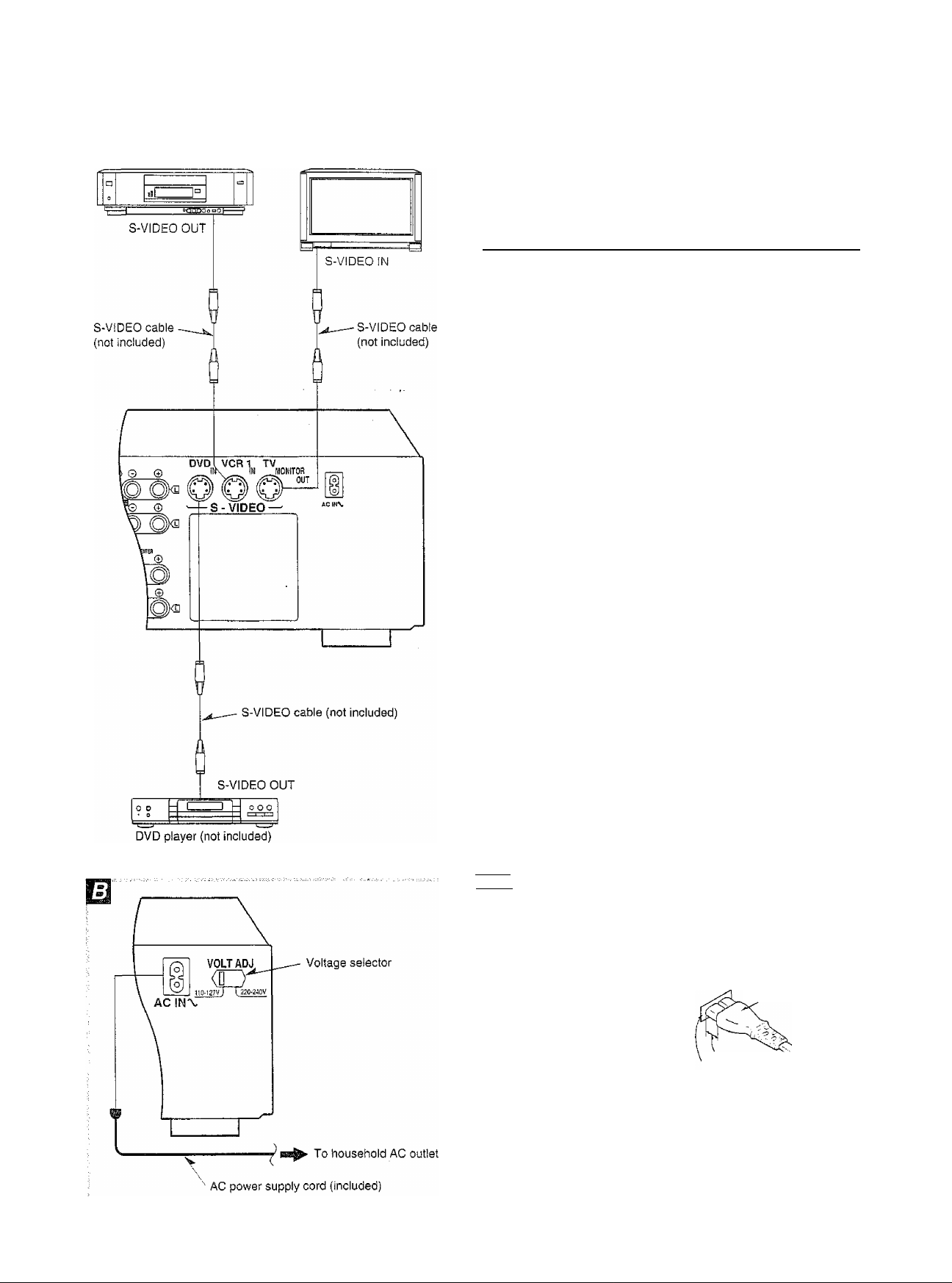
This receiver has S-VIDEO terminals for a DVD player, VCR (VCR
1 only) and TV,
Caufion when using a TV v/ith an S-VIDEO terminal
On some television models, the video signal from components
which do not use S-VIDEO input and are connected only to the
VIDEO terminals will not be shown on the television screen.
If this occurs, use one of the following methods to view the video
signal.
Does the television have a
“VJDEO/S-VIDEO” selector
switch?
YES
NO
Set the switch to “VIDEO",
If the television has two or more video input terminals
Connect the VIDEO terminal and the S-VIDEO
terminal to different video input terminals on the
television, and switch the picture on the televi
sion according to the video source being
played.
If the television has only one video input ter
minal
Disconnect the S-VIDEO cable connected to
the television’s S-VlDEO terminal and connect
only the video terminal.
When using S-VIDEO terminals be aware of the following.
Video signals input into the VIDEO terminals cannot be output from
S-VIDEO terminals or vice versa.
Connect this cord after all other cables and cords are connected.
(For areas except Australia and N.Z.)
Set the voltage selector to the voltage setting for the area in which
the unit will be used.
ggTsna
This unit will be seriously damaged if this setting is not made cor
rectly.
(For areas except Australia and N.Z.)
Insertion of Connector
Even when the connector is perfectly
inserted, depending on the type of
inlet used, the front part of the con
nector may jut out as shown in the
drawing.
However there is no problem using
the unit.
^ Approx.
"Appliance inlet
Connector
(Some areas)
if the power plug wilt not fit your socket, use the power plug adaptor
(included).
Page 10
An^fina connecf/ons
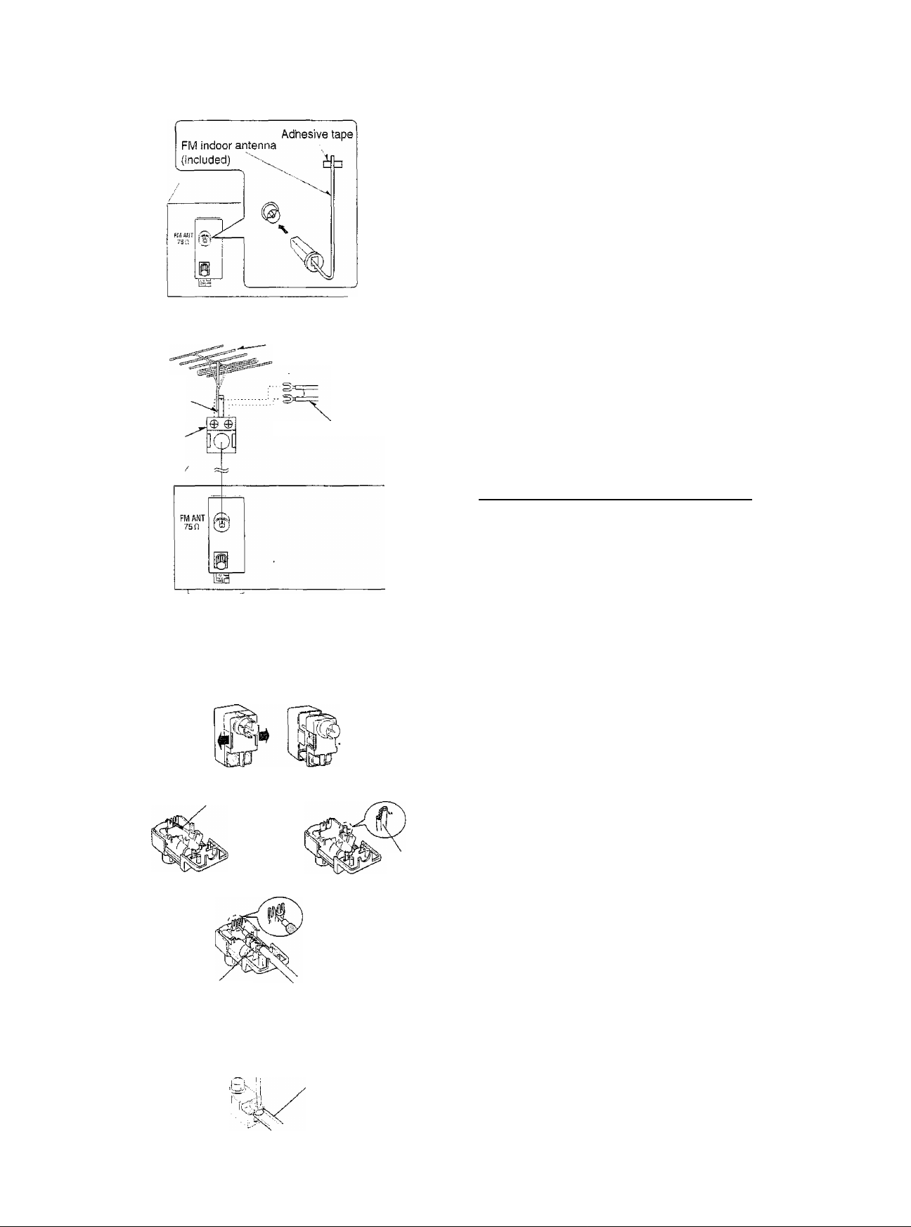
This antenna is normally sufficient for reception of FM broadcasts.
Attach to a wall (using tape) facing in the direction of best reception.
I
3
£
BQ
75 £1 coaxial
cable
(not included)
Antenna plug
{included)
FM outdoor antenna
(not included)
300 Q feeder wire (not included) |
For best reception
An FM outdoor antenna is recommended.
An outdoor antenna should be used when using this unit in moun
tainous areas or in spaces enclosed by reinforced concrete where
the FM indoor antenna (included) does not provide satisfactory
reception.
Disconnect the FM indoor antenna if an FM outdoor antenna is
installed.
An outdoor antenna should be installed by a qualified technician
only.
How to use the antenna plug (included)
Two types of wire are most commonly used for connection from the
antenna: 300 £2 parallel feeder wire or 75 £2 coaxial cable. For best
resistance to outside interference, the use of 75 £2 coaxial cable is
suggested.
M To connect a 75 U coaxial cable
(T.) Remove a piece of the outer vinyl insulator.
(|) Remove the cover while pulling the tabs.
f 1 'i
i (Z)
I (D
Press down with pliers.
20 mm
Lead wire
10 mm
If the tabs are pulled too hard, the casing may be damaged,
(3 ) Remove the lead wire and clamp it with the plastic bar.
(4) Install the coaxial cable.
Clamp the cable conductor, and wind it on so that it doesn’t
contact anything else.
Attach the cover.
9 To connect a 3Q0 O. feeder wire M
Loosen the screw to connect the feeder wire and tighten it to secure
the connection.
Plastic bar L
300 £2 feeder wire
(not included)
Page 11
Antenna connections
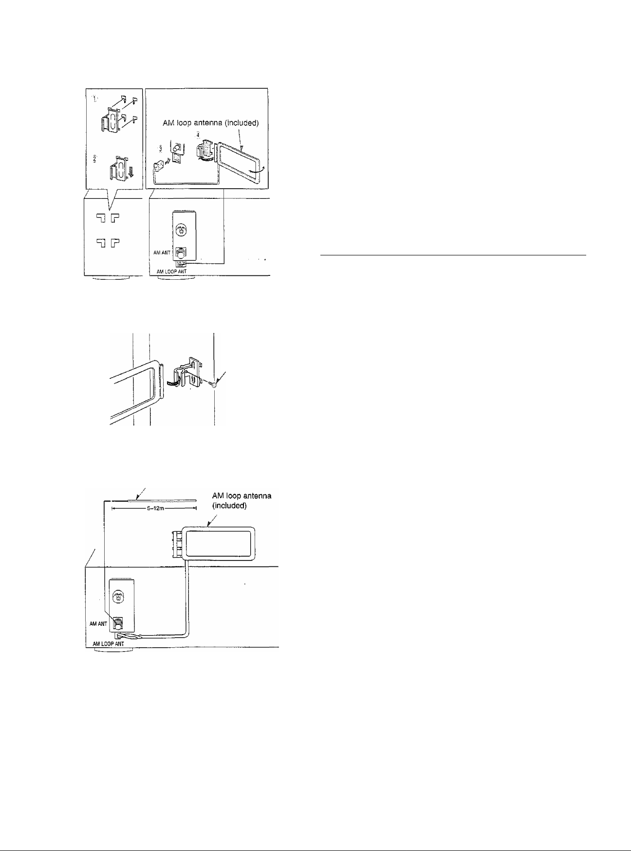
This antenna is normally sufficient for reception of AM broadcasts.
Fit the AM loop antenna holder (included) onto the rear panel of this
unit and then attach the AM loop antenna to the AM loop antenna
holder (facing in the direction of best reception).
Pay attention to the following points when mounting the antenna.
e Do not mount it close to power cords, speaker wires or metal sur
faces (Doing so will result in noise),
e Do not mount it dose to a tape deck. When the tape deck is being
used, chirping or beeping sounds may result.
When mounting the antenna to a column, q wall or rack
Mount the antenna so that the hinge is vertical.
■
4»
£
Q>
QQ
m
E
Vinyl-covered wire
(not included)
Screw (included)
An outdoor antenna should be used when using this unit in moun
tainous areas or in spaces enclosed by reinforced concrete where
the AM loop antenna (included) does not provide satisfactory recep
tion.
Stretch 5 to 12 m of vinyl-covered wire horizontally across a window
frame or other convenient location, keeping it as high as possible
from the ground.
When the unit is not in use, disconnect the outdoor antenna to pre
vent possible damage that may be caused by lightning. Never use
an outdoor antenna during an electrical storm.
Be sure to connect the AM loop antenna even when AM outdoor
antenna is used.
Page 12

I
0Ì
in
z>
speaker connections
Center speaker
(not included)
Front speaker (Left)
(not included)
Front speaker (Right)
(not included)
/Ì
Front speakers
Place the front left/right speakers at both the left and right sides of
the TV at seated ear height so that there is good coherency
between the picture and sound.
Center speaker
Place the center speaker underneath or above the center of the TV.
Aim the speaker at the seating area.
I
TV (not included)
Surround speaker
(Left) (not included)
Other connections are possible depending on the speaker system you have.
For details, see the operating instructions that came with your speaker system.
Subwoofer
(not included)
Surround speaker
(Right) (not included)
tener, and about one meter higher than ear levei.
The subwoofer can be placed in any position as long as it is at a
Surround speakers
Place the surround speakers on the side of or slightly behind the lis
Subwoofer
reasonable distance from the TV.
Note that some experimentation in placement of the subwoofer can
yield the smoothest low frequency performance. Placement near a
corner can increase the apparent output level, but can result in
unnatural bass.
Speaker cables (not included)
Page 13

To connect to the “A” terminais
Front speaker (Right)
(not included)
Front speaker (Left)
(not included)
0}
3
I
To connect to the “B” terminals
For connection to a second pair of speakers.
Front speaker (Right)
(not included)
Speaker impedance: AorB:
A and B: 8-16
BI-WIRE: 6-16 £2
Connecting the speaker cable
1 2 3
4-16 a
V V
Speaker cables (not included)
NO
Front speaker (Left)
(not included)
mm
To prevent damage to circuitry,
never short-circuit positive (-i-) and
V
negative (-) speaker wires.
Page 14

splicer connections
GQ
I
§
Q>
Center speaker
Speaker impedance: 6-16
□
Surround speakers
1. Both surround speakers must be connected before sound can be heard from them.
2. Do not connect the surround speakers to the front speaker terminals, as they may be damaged,
Page 15

Subwoofer
To connect a subwoofer which does not have a built-in amplifier
Subwoofer (not included)
Page 16

Basic operations
Before operation, set VOLUME to the “MIN” position.
Press POWER.
Press A and/or B, or to select the
speaker system(s) to be used.
Bl-AMP : VOLUME'
SUBWOOFER
LEVEL
POWER
-—SPEAKERS—□ □ □
SPEAKERS^ nlinraaan
A, B and
of the unit.
When
nate.
If the button is pressed once more, the indicator will switch off
and no sound will be heard from the speakers.
EIHandA, or
the same time.
The BI-AMP indicator goes out if a Dolby Pro Logic or SFC
mode is turned on or if the DVD 6CH INPUT mode is select
ed.
m refer to the speaker terminals at the rear
is selected, the Bi-AMP indicator will iliumi-
and B cannot both be used at
Turn INPUT SELECTOR to select and start
the desired source.
{Refer to the appropriate operating instructions for details.)
The indicator which corresponds to the selected input source
will illuminate.
The selected source and “INPUT" will be shown on the dis
play,
VCR 1: To watch video tapes {VCR 1)
TV/VCR 2; To watch TV or video tapes {VCR 2)
VCR 3: To watch video tapes (VCR 3)
DVD: To watch DVD
TAPE: To listen to cassette tapes
CD: To listen to compact discs
TUNER: To listen to radio broadcasts
PHONO: To listen to phono discs
INPUT SELECTOR
B
VOLUME
MIN MAX
Selected source
!f a Dolby Pro Logic or SFC mode has been select
ed
After displaying the selected source, the display will then
change to show the Dolby Pro Logic or SFC mode and
“INPUT” will go out.
If the source chosen was TUNER then the display will change
again to show the frequency.
iCTsa
To watch a video {or DVD) or the TV, set the TV to either the
TV mode or VIDEO mode.
For your reference
If you are using VCR and you select TAPE, CD, TUNER, or
PHONO, the picture will remain on the screen.
Adjust the volume level.
If using a subwoofer, adjust its volume with SUBWOOFER
LEVEL.
If the subwoofer isn’t being used, be sure to set SUB
WOOFER LEVEL to MIN.
After listening is finished
Be sure to reduce the volume level, and switch the power to the
standby condition by pressing POWER,
Page 17

-—SPEAKERS
o o
■ V,
----------
-
cow IMP
SPEAKERS
Bask operations
When using speakers under 6 O O
Press and hold A or B until LOW IMP lights up on
the display.
If even one of the speakers being used has an impedance under 6
n, press and hold down either button A or button B for 4 seconds or
more to set the impedance on the main unit to LOW.
{Press and hold down once again for 4 seconds or more to turn it
off.)
Note that when ‘'LOW IMP” is illuminated, speakers A and B cannot
both be used at the same time.
To change a speaker:
e.g. To use speaker B, press A goes out), and then press B to
activate speaker B.
To turn off the blue light
Turning off the blue light sometimes improves video viewing in dark
or dimly lit rooms.
Press and hold CENTER MODE for 4 seconds.
I
I
Press and hold it once again to turn the light back on.
a
This light comes on when the power is turned on.
If the front cover comes off @
0 Insert the cover as shown in the illustration.
0 Ensure the cover is parallel to the unit, then
press firmly down on the levers until they click
into place.
0 Check that the cover now moves correctly.
If it does not, remove it and repeat the above procedure.
Page 18

Bo5fc operations
Press PUSH OPEN.
Turn BASS to adjust the low frequency sound.
Turn TREBLE to adjust the high frequency sound.
%
I
k
O
Turn BALANCE to adjust the left/right sound bal
ance.
Press MUTING.
The message “MUTING ON NOW” runs repeatedly from right to left
across the display as long as the muting function is on.
Press once again to return to the previous volume level.
When the receiver is turned off, the muting operation will be auto
matically cancelled.
0 Reduce the volume level.
0 Connect the headphones.
Plug type: 6.3 mm stereo
0 Adjust the volume level.
If you do not want sound from the speakers, press the SPEAKERS
button{s) and check the speaker tndicator(s) goes out.
If a subwoofer is connected to your system, silence it by turning the
SUBWOOFER LEVEL control on the receiver to MIN.
I2BS
Avoid listening for prolonged periods of time to prevent hearing
damage.
Page 19

-SUBWOOFER
ADAPTIVE
CONTROL
O
BI-AMP . SUBWOOFER
BALANCE ■ LOW PASS FILTER
LF HF 50Hz 200Hz
Basic operations
This button balances low volume sounds by boosting bass sound
pressure of the front speakers and subwoofer.
This function allows you to enjoy balanced sounds even if the vol
ume is low.
Press SUBWOOFER ADAPTIVE CONTROL.
The message “ON” will appear on the display for 2 seconds.
SUBWOOFER ADAPTIVE CONTROL indicator will light up.
To return to the previous condition, press once again.
The message “OFF” wilt appear on the display for 2 seconds and
the indicator turns off.
ilEI
This button can be used only when TVA/CR 2 is selected as the
input source.
The TVA/CR 2 input select button works for both TV input and input
from the source connected to the front side “VCR 2” terminals. {See
page 7.)
Set ” M. TV” or “ VCR 2” position.
■
c
.o
I
O
-SUBWOOFER ■
Bl-AMP
BALANCE
' vi-i
f \
LF HF
m TV
^ VCR 2
inniia
i i \\ I
/_/ /1/
/ / /
/ //
/ ill
t / 1 t i 1
/ M /
/7 /„ / 1 /_
Turn Bi-AMP BALANCE to adjust the LF/HF
balance.
This adjusts the high and low frequency output of bi-wired front
speakers.
The setting depends on the speakers being used.
Adjust the balance to suit your room's acoustics and the features of
the speakers.
When BI-AMP is ON
“BI-AMP” will illuminate.
BI-AMP makes use of the special characteristics of bi-wiring to
reproduce high quality stereo sound.
wm
Bl-AMP will turn off and the indicator will go out in the following
cases:
» If any of the Dolby Pro Logic or SFC modes are turned on,
• If DVD 6CH INPUT is selected.
Only when a subwoofer is connected
SUBWOOFER
LOW PASS FILTER
(G
Turn SUBWOOFER LOW PASS FILTER to select a
suitable frequency.
The setting depends on the room's acoustics, the peculiarities of
the subwoofer, and the interaction of the subwoofer and the front
speakers.
Adjustments can not be made when DVD 6CH INPUT has been
selected.
Page 20

Lisfenirtg to radio broadcasts
Use the tuning buttons to tune-in radio stations.
Turn INPUT SELECTOR to select TUNER.
Press -BAND to select “FM” or “AM”.
I
,o
A
s
O
-FM MODE
INPUT SELECTOR
/ t I n IJ_ l_J
/ t f f ^ L. f 1
/ n/i
1 f /
Selected band
tn
1 /”//“/ :
A Z) HHi
B Press TUNING
(V)
or
(A)
to tune to the
desired frequency.
“TUNED” lights up when tuned.
“STEREO” lights up when an FM stereo broadcast is
received.
To make an automatic search for stations
If TUNING( V) or (A) is held down for an instant until the fre
quency begins to scroll, the broadcast stations are tuned in
automatically when one is found.
Tuning may stop automatically if any jamming is encoun
tered.
If noise is excessive in the FM stereo mode
Press and hold -FM MODE for 2 seconds.
(“STEREO” will go out, and "MONO" will light up)
The broadcast will be monaural, but noise will be reduced.
If the button is pressed and held for 2 seconds once more, the
stereo mode will be resumed.
To change the AM frequency step
Press and hold -BAND for about 3 seconds when AM band is
selected.
(The frequency step changes to 10 kHz per step.)
To return to the previous step, press and hold -BAND for about 3
seconds again.
TIJMING
A
TUNED ¡1/1
STEREO ""
/ / /
7 / / /
uu.
11 1
t L_/ «iHi
Page 21

oooo
OOOC3
o o o
o O o
OOD
o Q o
oo o
oooo
0"a"C)\0
OOOi;
tOQ-Q.j
oo O o
oooo
Listening to radio broadcasts
by remote, control only
Specify the frequency using the numeric buttons on the remote controi transmitter to directly tune to the desired station.
Press TUNER/BAND.
This will set the remote controi to operate the tuner.
The selector on the receiver wii! change to TUNER.
Each time the button is pressed, the band will change as foilows,
FM^AM
Press DIRECT TUNlNG/DiSC ENTER.
While cursor display is flashing (approx. 10 seconds)
Press the appropriate numeric buttons to
enter the frequency.
If the desired FM frequency is 107.90 MHz, press
If the frequency has been input correctly, the displayed fre
quency will blink once.
■
c
I
1 2 3
ooo
666
6666
/ ft/r
/1/7
/ / /
! n f
III
Selected band
M/ ■ .
/!\
7 / /
/ HHi
liBiSi
1. If no button is pressed while the cursor display is flashing,
the display will return to the frequency which is currently
being received. To re-specify the frequency, repeat the
procedure from step 2.
2. If the frequency has not been input correctly, “ERROR"
wilt be displayed. In this case, re-enter the frequency.
Page 22

•s
§
<§■
MEMORY
iL_
V / /
/_/ / /_/ / /
A _^ MHl
Listening to radio broadcasts
Presetting radio stations into the memory channels of this unit
makes selecting stations simple.
A total of 30 FM and AM stations can be preset.
Please i-emember this
If a new broadcast station is preset into a channel, the setting for
the broadcast station which was previously entered in that channel
will be automatically erased.
Automatic memory presetting
Automatic memory presetting allows this unit to automatically
search for broadcast stations and then preset them into memory,
With this method, the channels that can be preset into the memory
are set as follows for different bands.
When FM stations are preset,
For FM stations
When FM and AM stations are preset.
For FM stations
For AM stations........................................................................21-30
..........................................................................
..........................................................................
1-30
1-20
/ / /
/_ / /
Gl- . .
Set to the frequency from which you want to start automatic memory presetting.
(See page 20, 21.)
Press MEMORY until the frequency begins to change.
(Automatic memory presetting will start.)
/
1
During automatic memory presetting, the memory indicator
will flash while the frequency scrolls.
To stop, press MEMORY once again.
When a broadcast stoHon is preset ^
The memory indicator and the preset channel number will be
displayed for approximately 1 second.
When presetting is completed
The last broadcast station to be preset will be displayed.
Frequencies may not be preset correctly in cases where the
broadcast waves are too strong or too weak. In such cases, carry
out presetting manually. (See page 23.)
Page 23

Lisfenlng to radio broadcasts
Manual memory presetting
The desired stations can be preset into the desired channels by the
user.
Set to the desired frequency.
(See page 20, 21.)
if interference or static is keeping you from enjoying an FM
broadcast, press and hold -FM MODE and change to
monaural
You can preset the station in monaural just as in stereo.
Press MEMORY.
To cancel the memory function, press MEMORY again.
■
-FM MODE
MEMORY
TUNING
TUNEO . n/f
STEREO^'—
I l_t
/ / /
/ / / 1
/ it
/ / i__r ! t /
О U, / LJ Шг
w/
1
. /IS ^ ■
Press TUNING (V) or (A) to select the
desired channel.
Holding the buttons down lets you scroll through channels
faster.
Press MEMORY.
The channel will blink on the display.
To continue presetting
Repeat steps 1 through 4,
j
I
MEMORY
TUNED
STEREO
f / /
ЛЛ
/
1 1 /
/
1 1 1
/“ о
/_/ /_/,
n 1
t /_/ MHi
Page 24

I
c
0
■c
1
O
PRESET
Listening to radio broadcasts
To listen to preset channels
Press PRESET.
Press TUNING (V) or (A).
Holding down the buttons lets you scrott through channels
faster.
The channel number will be changed for approximately 5 sec
onds.
Select the desired channel number during that time.
After 5 seconds, the display will change from the channel
number to the frequency.
if you press PRESET while the channel number is displayed, the
display will change to the frequency.
To confirm the channel number of the broadcast station
being received
PRESET
TUNING
CZIZj
. m . .
TUNED n A
STEflEO
t II
Press PRESET.
(The channel number will be displayed for approximately 5 second.)
ffnsffll
The channel number is not displayed if you change the frequency or
FM mode setting.
For your reference
M/ ■ ■ ■
Ill
III
/
/
/1\
/_/ Ill
/_/ L./,
1 i_/ MHz
Even if the power cord is disconnected from the household AC out
let, the memory will retain its contents for approximately one month.
If frequency presettings are accidentally erased
Program the presettings once again.
The power cord should remain connected for one hour or more for
the memory back-up to be effective.
n
m
Page 25

Enjoying sound with DOLBY PRO LOGIC
Surround
speaker (Left)
m
Front
speaker (Left)
Front
speaker (Left)
Dolby Pro Logic lets you enjoy movie software (video tapes and
DVDs) in your own home with the same powerful stereophonic
effect found in movie theaters. This unit has two Dolby Pro Logic
modes: SURROUND and 3 STEREO,
SURROUND B
By reproducing the feeling of depth and movement of sound, video
software or compact discs recorded with Dolby Surround provide
the listener with a feeling of presence like that of a movie theater.
3 STEREO El
You can enjoy audio/video sources with clear sound, more pres
ence and a good feeling of orientation. 3 STEREO can be used with
stereo sources not encoded with Dolby Surround.
BI-AMP and Dolby Pro Logic cannot be used at the same time.
If you are using BI-AMP and you select Dolby Pro Logic, BI-AMP
will turn OFF and the BI-AMP indicator will go out,
□D PRO LOGIC
For SURROUND mode
/_ / ;/_//_// M /
\ l \ 1 n 1 / Ü n
nil
DO PRO iOiHC
For 3 STEREO mode
1
_/
/ i ! ) 1
□3 PRO LOGIC
J] / / il I n/i Ì Ì I
i M I t i \ I ! I i t
□□ PRO LOGIC SOliNQ MOOR
n i 77
^ SOUND MODE
Ì / /
/_ /_/
4 SOUND tAODE
17!^
• When ready to adjust speakers output level, situate yourself
where you would normally be listening.
• The subwoofer does not put out a test signal. Ensure no sound
comes from the subwoofer during the test by turning SUB
WOOFER LEVEL to MIN.
® First turn ON the speakers with the speaker select button on the
receiver.
® If front speaker volume Is unbalanced, adjust the balance with the
BALANCE control.
Press □□ PRO LOGIC io select SURROUND
mode.
Select 3 STEREO if surround speakers have not been con
nected.
Press CENTER MODE to select the correct
center mode.
When the button is pressed, the current center mode is dis
played.
Pressing it again changes the center mode.
NORMAL
When the center speaker is smaller than the front speakers.
WIDEBAND
When the center speaker is the same size as or larger than
the front speakers.
PHANTOM manmm
When no center speaker is connected.
In the PHANTOM mode, the sound which would have been
sent to the center speaker will be divided equally between
both the left and right front speakers.
(Continued on next page)
Page 26

OFF/ON ■
OOOO
oooo
C) t ) ( )
o O o
ODD
o O Q
oo cEl-
QPPg
OOOO
oooo
oooo
oooo
ool^
TEST
Enjoying sound with DOLBY PRO LOC/C
I3B
Press TES i to output a test signal.
The speaker outputting the test signal is displayed while the
test is running.
L : Front speaker (Left)
C: Center speaker
R : Front speaker (Right)
S : Surround speakers
For SURROUND mode
L-C-R—S
In the PHANTOM mode, the center speaker is OFF, so there
is no center test signal and “C” is not displayed.
I
S
For 3 STEREO mode
L —C-R
K
Press VOL (“) or (+) to set the volume level
TEST
— CENTER+
oo
- SURROUND+
0.0
or
/ /_ /_ r 7
/ / / / /
Speaker channel
Selected channel
/
■
□QPPO LOOtC I ^4 SOUND MODE
□n pno LOGIC I -^SpUNCMODE
/
”/ / 77
T _/ o
Output level
normally used for enjoying the source
The following steps are for setting the output level of the front
speakers and the center/surround speakers to the same listening level.
by^retri oté: contro I on ly£
Press CENTER (-) or (+), or SURROUND (-) or
(+) to adjust the output level.
Adjust the output level of each speaker from the listening
position until they are all identical.
Decrease the output level.
+: Increase the output level.
Output level can be varied within a range of -12 dB to +12 dB
with front speaker output level serving as the zero point.
1. During step 5 above the lest signal sequence is interrupt
ed and the signal will only come from the selected speak
er.
The sequence will resume when adjustments are stopped.
2. Remember you cannot adjust the output level of the sur
round speakers if you selected the 3 STEREO mode in
step 1.
To stop the test signal
Press TEST.
To turn off the Dolby Pro Logic systems
Press OFF/ON.
Press once again to turn it on,
Page 27

Enjoying sound with DOLBY PRO LOGIC
□n PRO LOGIC
/_ / / /_/ O / f / Tt
_/ / t / i u JL/
QQ PRO LOGIC i SOU№ WOE
Itf~’ l
J./ L. U
/ nr
in _/
on PRO LOGIC^SOUNDMpDC
Dr 1
L. Cf
gafejtia&a&toaf..v: ■■ ..t-;
When enjoying with SURROUND only
Adjust the sound from the surround speakers untii the proper effect
is produced.
’V
Press □□ PRO LOGIC to select the SURROUMD mode.
Press DELAY TIME to set the time.
When the button is pressed, the current delay time is dis
played.
Pressing it again changes the delay time.
Each time the button is pressed, the delay time will increase
by 5 ms within a range of 15 ms to 30 ms.
The standard setting is 20 ms.
To colculate the delay time 0
Di: Distance from front speakers
D^: Distance from surround speakers
• If Oi is equal to or less than D2
Set to 15ms.
9 If D2 is less than Di
Start at 15ms and increase by 5 ms for every 1.5 m of difference
between Di and D2.
■
.1
*c
I
Front
Speaker (Left)
Surround
speaker (Left)
Center
speaker speaker (Right)
Front
Surround
speaker (Right)
Page 28

Enjoying sound with DOLBY PRO LOGIC
Turn INPUT SELECTOR to select and start
the desired source.
Press □□ PRO LOGIC to turn on the Dolby
Pro Logic system and select the desired
mode.
When the button is pressed, the Dolby Pro Logic mode is dis
played.
Pressing it again changes the Doiby Pro Logic mode.
1
c
s
(U
O
OFF/ON
B
When employing SURROUND, use software recorded in
Dolby Surround,
For your reference
You can set the Dolby Pro Logic mode for each source.
Each source will retain the selected mode.
To turn off the Dolby Pro Logic systems
INPUT SELECTOR
□□ PRO LOGIC
Press OFF/ON.
Manufactured under license from Dolby Laboratories Licensing
Corporation.
DOLBY, the double-D symbol □□ and “PRO LOGIC” are trade
marks of Dolby Laboratories Licensing Corporation.
Page 29

П
OFF/ON
INPUT SELECTOR
Enjoying sound with SFC
' SFC is the abbreviation of Sound Field Control.
The SFC function gives presence and spread thereby enhancing
and enriching the music or movie.
Read the following explanations in order to better understand how
to make your selection.
HALL
This mode imparts a reflection and spread which will make you feel
as if you are in a large concert hail.
CLUB
Like a jazz club, this mode provides an exciting and intimate atmos
phere. It simulates the sound field of a relatively small room having
a low ceiling and hard reflective surfaces, for a “live” sound with
enhanced presence to bring the performers up close.
LIVE
Primarily for vocal pieces, this mode adds gloss to the vocals and
you’ll feel as though you were hearing a live stage performance.
THEATER
You can clearly perceive the directions and source of the movie.
Real ambience of sound can also be recreated naturally using this
mode.
THEATER mode can be used with stereo sources not encoded with
DOLBY SURROUND.
LI\ÌE'';:-r.,THEATEH;iSI!i1UrArEDÌ
о о о о о
--
---------------------
SFC
----------------------
Selected SFC mode
-
f t f / 1
1/
^a^SOUNOWDE
When using Dolby Surround encoded materials, select DOLBY
PRO LOGIC SURROUND.
SIMULATED (SIM SURR)
Choose this mode if little or no sound will be heard from the sur
round speakers.
You can feel as if you were in a more expanded space adding to
the actual sound from the source.
This mode also adds effect to monaural sources by outputting
sound from surround speakers.
You can adjust center speaker volume only in the theater mode.
The center speaker is not used in the hall, and simulated modes.
Turn INPUT SELECTOR to select and start the desired source.
Select the desired SFC mode.
For your reference
You can set the SFC mode for each source,
Each source will retain the selected mode.
To turn off the SFC function
Press OFF/ON.
Press once again to turn it on.
mm
Bl-AMP and the SFC modes cannot be used at the same time.
If you are using Bl-AMP and you select an SFC mode, BI-AMP will
turn OFF and the Bl-AMP indicator will go out.
Page 30

I
c
0
1
Enjoying sound with SFC
With this unit, you can adjust speaker volume.
Adjust the field of sound while listening to a source.
To adjust the volume of the center and surround speakers
Center speaker volume can be adjusted only in the THEATER
mode.
Select the desired SFC mode.
Press CENTER (-) or (+), SURROUND (-) or
(+) to adjust the output level.
..
CENTEfl+
oo
or
■■ ■ ■ SURR0UW+
o„o
/ 7
-i-
Selected SFC mode
Selected channel
-1/ r
L.
Efsra < SOUND MODS
Page 31

________________________
o o o o o
-
---------------------
SFC
------------------------
MWiiM
Enjoying sound with SFC
To adjust the delay time
Select the desired SFC mode.
Press DELAY TIME to set the time.
When the button is pressed, the current delay time is dis
played.
Each time the button is pressed, the delay time will change.
The delay time increments are different depending on the
SFC mode.
Select a delay time setting to accommodate to your individual
needs.
SFC modes
HALL
CLUB
LIVE
THEATER
SIMULATED
Available delay time setting (ms)
40, 50, 20, 25, 30
15, 20, 25, 30,0
50,15, 20, 30, 40
20, 25, 30,40,15
15, 20, 25,30,40
I
•SZ
I
■■■ j
~ 1/ r
V l_
/_ 1
Selected SFC mode
it 1 / / it t
±n^ i^ f t _t
sowtOMOCE
nn
SOUNDniODE
Page 32

Enjoying sound with 6 channel discrete
This receiver can playback 6 channel discrete sound,
it has terminais for connecting to components with 6 channei dis
crete output, such as a DVD piayer.
5 channei discrete output makes piayback sound more real by
adding depth, movement, position and other characteristics to the
field of sound.
it wili make you feei as if you were at the movie theater when in
your own home.
To enjoy 6 channel discrete output sound
You have to connect a DVD piayer or other component that has 6
channel discrete output capabilities.
I
I
DVD 6CHINPUT
tllJIMim
Til /
±lt / n
Turn INPUT SELECTOR to select DVD.
Press DVD 6CH INPUT to select DVD 6CH.
Changes as foiiows, each time the button is pressed.
DVD6CHi=tDV0 (2CH)
if you press this button whiie another source {CD, PHONO,
etc.) is selected, the receiver switches the source to DVD and
engages the DVD 6CH INPUT mode.
Start the desired source.
Foiiow your equipment’s operating instructions.
You cannot select Dolby Pro Logic or any of the SFC modes while
in the DVD 6CH INPUT mode. If you try, the message “NOT POS
SIBLE IN 6CH DISCRETE INPUT’ will appear on the display.
t i il
u
l_l
/__ / /
Bi-AMP and DVD 6CH INPUT cannot be used at the same time.
If you are using BI-AMP and you select DVD 6CH INPUT, BI-AMP
will turn OFF and the BI-AMP indicator will go out.
Page 33

Making a recording
When you select DVD 6CH INPUT mode, only sound from the front
left and right speakers is recorded.
To record all 6 channels
Set the playback mode on your DVD player or decoder to 2 channel
(stereo) mode.
For details, see the instruction manual that came with the connect
ed equipment.
INPUT SELECTOR
o Id (DO
o
o ooooo o
o
oooooooo
Before recording, prepare the tape deck for recording (recording
level adjustment, etc.).
See-the tape deck’s operating instructions for details.
Turn INPUT SELECTOR to select the source to be recorded.
Any source can be selected except TAPE.
(only if you select TV/VCR 2 in the above step)
Set “ M. TV” or “ jsL VCR 2” position.
Begin recording on the tape deck.
Follow your tape deck's operating instructions.
Begin the source to be recorded.
Follow your equipment’s operating instructions.
You can record only on VCR 1.
Before recording, prepare the VCR 1 (VCR) for recording (recording
level adjustment, input selector setting, etc,).
See the VCR’s operating instructions for details.
Turn INPUT SELECTOR to select the source to be recorded.
Any source can be selected except VCR 1 (VCR) and TAPE.
Recording from the tape deck is not possible.
I
I
s
O
VCR 2
INPUT SELECTOR
(only if you select TVA/CR 2 in the above step)
Set TV”or“^ VCR 2” position.
Begin recording on the VCR.
Follow your VCR’s operating instructions.
Begin the source to be recorded.
Follow your equipment’s operating instructions.
For your reference
There are VCR 2 terminals at the front of this unit.
It is easier to carry out dubbing from a camcorder if it is connected
to the front terminals.
Page 34

I
с
,o
•£
WAKE
TIMER
SLEEP timer mode
n_ l__ 1^1
I I i~ i~ i~i
\
11 1
11 1
/ \
/ SLEEP
Timer function
There are two timer functions: the sleep timer and the wake timer.
• Sleep timer:
The unit turns off after a set time.
It can be set for 30. 60, or 90 minutes,
e Wake timer;
The unit can be set to turn on a certain number of hours after it is
turned off.
It can be set for 5, 7, or 9 hours.
(while listening to the radio)
Press TSMER to select the desired timer mode.
The timer mode changes as follows:
SLEEP —WAKE —OFF
t
___________________
(within 5 seconds)
Press TIMER and release when the time you require is displayed.
The display changes as foiiows:
• In sleep timer mode
30 — 60 — 90 (minutes)
t
___________
I
I
TIMER
POWER
WAKE timer mode
///////
l/\n / / 1 /_
inii/i / 1 1
VV ! i ! \ t_1 1 1
/_ ПЛ
t i I
\yVAK£l
/ 1 /
1 1 /
/ 1
\wake1 /
/ I \
WAKE
Q О / /”
/_/ i_i, t MHz
• In wake timer mode
/
\
5H —7H— 9H (hours)
t
___________
I
The frequency is displayed again 5 seconds after the setting
is completed.
Press POWER to turn off the power.
The WAKE indicator lights up.
Checking the remaining time on the sleep timer and the time set for the wake timer
Press TIMER once,
SS30
Do not press TIMER again before the remaining time
indication goes out.
The setting may change if you do this.
Changing a setting
Repeat steps 1 and 2,
To cancel the timer
Press TIMER until “OFF" is displayed,
“SLEEP" or “WAKE” will go out.
•
• The timers cannot be used together.
• The sleep timer turns off the receiver, and the wake timer turns on
the receiver, but they do not turn off/on any externally connected
components.
Page 35

Troubleshooting guide
Before requesting service for this unit, check the chart below for a
possible cause of the problem you are experiencing. Some simple
checks or a minor adjustment on your part may eliminate the prob
lem and restore proper operation.
Reference pages indicated in biack circles. (For example:
Problem
Probable cause(s)
While iistening io FiVt broadcasts
An unusual hissing noise is
heard when listening to the
broadcast in stereo, but not
heard when listening
monauraily.
Noise is excessive in both
stereo and monaural broad
casts.
The “STEREO” indicator or
the “TUNED” indicator flick
ers, without completely illu
minating.
Excessive distortion in the
sound of stereo broadcasts.
A slight noise may be heard because the method
used for modulation of FM stereo broadcasts is
different than that used for.monaural broadcasts.
Poor location and/or direction of the antenna.
Transmitting station is too far away.
Poor location and/or direction of the antenna.
Transmitting station is too far away.
Nearby building or mountain.
■if you are in doubt about some of the check points, or if the reme
dies indicated in the chart do not solve the problem, refer to the
directory of Authorized Service Centers (enclosed with this unit) to
locate a convenient service center, or consult your dealer for
instructions.
Suggested remedy
® Try reducing the treble sound by using the treble
control. (®)
e Try changing the location, height and/or direction
of the antenna, (i®)
® If an indoor antenna is being used, change to an
outdoor antenna. (Ì0))
© Try using an antenna with more elements.
« Try changing the location, height and/or direction
of the antenna. (®)
® If an indoor antenna is being used, change to an
outdoor antenna. (®)
©Try using an antenna with more elements.
Whsie listening to AM broadcasts
An unusual “beat” sound Is
heard.
A low-pitched “hum” sound
is heard when the station is
tuned.
A strange hissing noise is
produced continuously or
intermittently.
Unit is being used at the same time as the
television set.
Interference from adjacent broadcast signal.
The AM loop antenna connection wires are too
close to the power cord.
The power supply frequency from the power cord
is modulated and heard from the speakers.
Caused by the “discharge phenomenon" and the
“oscillation phenomenon” of electric appliances
(such as fluorescent lights, TV, small series-type
motors, rectification equipment, etc.).
Common Problems
Power will not switch ON.
No sound is heard.
Sound stops during a per
formance, or no sound is
heard when the power is
switched ON.
(The word “OVERLOAD"
appears on the display.)
The power cord plug is not completely inserted.
The speaker indicator(s) is(are) turned off.
The muting function is ON.
Connections to the speaker systems or external
equipment are incomplete or incorrect.
The incorrect input source has been selected.
The protection circuitry has functioned because
the positive and negative speaker connection
wires have “shorted,” speaker systems with an
impedance less than the indicated rated
impedance of this unit have been used or are
under severe use, such as through excessive vol
ume, excessive power or being in an excessively
hot environment.
©Turn off the television set, or use this unit farther
away from it.
©Try reducing the treble sound by using the treble
control. (®)
« Place the antenna connection wires and the power
cord farther apart.
9 install a special outdoor antenna. (®)
© Try placing this unit farther away from such equip
ment.
® Confirm that the power cord plug is connected
completely.
©Turn on the speaker indicator(s). (®)
« Press the muting button. (®)
• Check that all wires and cables are correctly con
nected. (0-®,
* Check that the correct source is selected.(©)
• Switch off the power, and after determining and
correcting the cause, switch on the power once
again.
• Use a speaker system of the proper impedance
rating. (®-®)
Page 36

Technical specifications (DIN 45 500)
Ki AMPLIFIER SECTION
Power output (at 240 V for Australia and N.Z.
(at 127 V for others)
DIN 1 kHz(T.H.D. 1%)
20 Hz-20 kHz continuous power output
both channels driven
Total harmonic distortion
rated power at 20 Hz-20 kHz
half power at 1 kHz
Power output at the Dolby Pro Logic operation
DIN 1 kHz(T.H.D. 1%)
Front (for Australia and N.Z.) 2X100 W (6 U)
(for others) 2X85 W (6 ii)
Center (for Australia and N.Z.) 100 W (6 Q)
Surround (for Australia and N.Z.) 2X100 W (6 O)
- (for others) 2X85 W (6 ii)
Subwoofer (fslOO Hz) (for Australia and N.Z.) 100 W (6 i2)
Power bandwidth
both channels driven, -3dB 10 Hz-40 kHz (6 il)
Damping factor 30 (6 ii)
Load impedance
Front
AorB 4-16 Q
A and B 8-16 Q
BI-WIRE 6-16 0
Center 6-16 O
Surround 6-16 0
Subwoofer 6-16 0
Frequency response
PHONO RIAA standard curve
CD, TAPE, DVD, VCR 1, TVA/CR 2, VCR 3
Input sensitivity and impedance
PHONO 3 mV/ 47 kO
CD, TAPE, DVD, VCR 1, TV/VCR 2, VCR 3 200 mV/ 22 kO
S/N at rated power (6 O)
PHONO 70dB(IHF, A:80dB)
CD, TAPE, DVD, VCR 1, TVA/CR 2, VCR 3
Tone controls
BASS
TREBLE
Output voltage
TAPE REC (OUT), VCR 1 OUT
Channel balance (250 Hz-6.3 kHz)
Channel separation
Adaptive control (volume at-30 dB)
Headphones output level and impedance
Subwoofer cut off frequency control
2X100 W (6 Ì2)
2X80 W (6 П}
0.05% {6 Q)
0.03% (6 a)
(for others) 85 W (6 Q)
(for others) 85 W (6 Q)
(30 Hz-15 kHz) ±0.8 dB
10 Hz-40 kHz, ±3 dB
75 dB (IHF, A: 85 dB)
50 Hz. +10 to -10dB
20 kHz, +10 to -10 dB
200 mV
±1 dB
55 dB
. 50 Hz, +Э dB
430 mV/330 a
50-200 Hz
Total harmonic distortion
MONO
STEREO
S/N
MONO
STEREO
Frequency response
20 Hz-15 kHz
Aiternate channel selectivity
£400 kHz
Capture ratio
Image rejection at 98 MHz
IF rejection at 98 MHz
Spurious response rejection at 98 MHz
AM suppression
Stereo separation
1 kHz
Carrier leak
19 kHz
38 kHz
Channel balance (250 Hz-6.3 kHz)
Limiting point
Bandwidth
IF amplifier
FM demodulator
Antenna terminal
60 dB (75 dB, !HF)
58 dB (71 dB.iHF)
-30dB(-35 dB, IHF)
-50 dB (-55 dB, IHF)
75 ii (unbalanced)
0.2%
0.3%
+1 dB, -2 dB
65 dB
1.5 dB
40 dB
70 dB
70 dB
50 dB
40 dB
±1.5 dB
1.2 pV
180 kHz
1000 kHz
m AM TUNER SECTION
Frequency range
Sensitivity
Selectivity (at 999 kHz)
IF rejection (at 999 kHz)
522-1611 kHz (9 kHz steps)
530-1620 kHz (10 kHz steps)
20 pV, 330 pV/m
55 dB
50 dB
m VIDEO SECTION
Output voltage at 1 V input (unbalanced) 1 ±0.1 Vp-p
Maicimum input voltage 1.5 Vp-p
Input/output impedance 75 U(unbalanced)
m GENERAL
Power supply
For Australia and N.Z.
For others
Power consumption
Dimensions (WXHXD)
Weight
Notes:
AC 110-127 V/220-240 V, 50/60 Hz
1. Specifications are subject to change without notice.
Weight and dimensions are approximate.
2. Total harmonic distortion is measured by the digital spectrum
analyzer.
AC 230-240 V, 50 Hz
300 W
430X158X378.4 mm
11 kg
m FM TUNER SECTION
Frequency range
Sensitivity
S/N 30 dB
S/N 26 dB
S/N 20 dB
IHF usabte sensitivity
IHF 46 dB stereo quieting sensitivity
87,50-108.00 MHz
1.5pV/75a(IHF’58)
Matsushita Electric Industrial Co., Ltd.
Osaka 542-8588, Japan
1,5pV/75n
1.3 pV/75 a
1.2 pV/75 Q.
22 pV/75
Maintenance
If the surfaces are dirty
To clean this unit, wipe with a soft, dry cloth.
If the surfaces are extremely dirty, use a soft cloth dipped in a soapand-water solution or a weak detergent solution,
« Never use alcohol, paint thinner or benzine to clean this unit.
»Before using chemicaity impregnated cloth, read the instructions
that came with the cloth carefully.
RQT4465-L
H0593V0
 Loading...