

Panasonic SA-AK52 Schematic
ORDER NO. MD0101010C3
CD Stereo System
SA-AK52
Colour
(S)... Silver Type
Area
(GC)...Asia, Latin America, Africa and Middle Near East
TAPE SECTION :
AR2 MECHANISM SERIES
CD SECTION :
RAE0152Z-3 TRAVERSE DECK SERIES
Specifications
■ AMPLIFIER SECTION
PMPO 2300 W
RMS power output
THD 10%, both channels driven
80 Hz, both channel driven
(Low channel) 100 W per channel (6 Ω)
1 kHz, both channel driven
(High channel) 40 W per channel (6 Ω)
Total Bi-Amp power 140 W per channel
Input sensitivity
AUX 250 mV
MIC 0.7 mV
Input Impedance
AUX 13 kΩ
MIC 680 Ω
■ FM TUNER SECTION
Frequency range 87.5 - 108 MHz (50 kHz steps)
Sensitivity 2.5 µV (IHF)
S/N 26 dB 2.2 µV
Antenna terminal(s) 75 Ω (unbalanced)
■ AM TUNER SECTION
Frequency range
MW 522 - 1629 kHz (9 kHz steps)
520 - 1630 kHz (10 kHz steps)
SW 3.200 - 7.350 MHz (0.005 MHz
steps)
9.400 - 21.750 MHz (0.005 MHz
steps)
Sensitivity
MW
S/N 20 dB (at 999 kHz) 560 µV/m
SW
S/N 20 dB (at 5.3 MHz) 35.5 µV/m
■ CASSETTE DECK SECTION
Track system 4 track, 2 channel
Heads
Record/playback Solid permalloy head
Erasure Double gap ferrite head
Motor DC servo motor
Recording system AC bias 100 kHz
Erasing system AC erase 100 kHz
Tape speed 4.8 cm/s
Frequency response (+3 dB, -6 dB at DECK OUT)
NORMAL (TYPE I) 35 Hz - 14 kHz
HIGH (TYPE II) 35 Hz - 14 kHz
S/N 50 dB (A weighted)
Wow and flutter 0.18% (WRMS)
Fast forward and rewind time Approx. 120 seconds with
© 2001 Matsushita Electronics (S) Pte Ltd. All rights
reserved. Unauthorized copying and distribution is a
violation of law.
SA-AK52
C-60 cassette tape
■ CD SECTION
Sampling frequency 44.1 kHz
Decoding 16 bit linear
Beam source/wave length Semiconductor laser/780 nm
Number of channels Stereo
Frequency response 20 Hz - 20 kHz (+1, -2 dB)
Wow and flutter Below measurable limit
Digital filter 8fs
D/A converter MASH (1 bit DAC)
■ GENERAL
Power supply AC 110 V/127 V/220 V/230-240V,
Power consumption 180 W
50/60 Hz
Power consumption in standby mode
0.8 W
Dimensions (W x H x D) 250 x 332 x 316 mm
Mass 9.0 kg
■ SYSTEM
SC-AK52(GC) Music Center: SA-AK52(GC)
Speaker: SB-AK52(GC)
Notes:
1. Specifiacations are subject to change without notice. Weight and
dimensions are approximate.
2. Total harmonic distortion is measured by the digital spectrum
analyzer.
3. The labels “High” and “Low” on the rear of the speakers refer to
High frequency and Low frequency.
CONTENTS
Page Page
1 Before Use
2 Before Repair and Adjustment
3 Protection Circuitry
4 Accessories
5 Handling Precautions For Traverse Deck
6 Precaution of Laser Diode
7 Operation Procedures
8 Operation Checks and Main Component Replacement
Procedures
9 Self-Diagnostic Function
10 Descriptio n of Error Code
11 CD Test Mode Function
3
3
12 Measurem ents and Adjustments
3
13 Illustration of IC’s, Transistors and Diodes
14 Terminal Function of ICs
3
4
15 Block Diagram
5
16 Schematic Diagram
17 Printed Circuit Board
6
18 Wiring Connection Diagram
8
19 Troubleshooting Guide
18
20 Parts Location and Replacement Parts List
19
20
20
24
25
28
34
48
58
59
60
2
1 Before Use
Be sure to disconnect the mains cord before adjusting the voltage selector.
Use a minus(-) screwdriver to set the voltage selector (on the rear panel) to the voltage setting for the area in which the unit will
be used. (If the power supply in your area is 117V or 120V, set to the “127V” position.)
Note that this unit will be seriously damaged if this setting is not made correctly. (There is no voltage selector for some countries,
the correct voltage is already set.)
2 Before Repair and Adjustment
Disconnect AC power, discharge Power Supply Capacitors C531, C532, C533, C534, C579 through a 10Ω, 5W resistor to ground.
DO NOT SHORT-CIRCUIT DIRECTLY (with a screwdriver blade, for instance), as this may destroy solid state devices.
After repairs are completed, restore power gradually using a variac, to avoid overcurrent.
Current consumption at AC 110 V, 60 Hz in NO SIGNAL mode should be ~650mA respectively.
3 Protection Circuitry
The protection circuitry may have operated if either of the following conditions are noticed:
•
No sound is heard when the power is turned on.
•
Sound stops during a performance.
The function of this circuitry is to prevent circuitry damage if, for example, the positive and negative speaker connection wires are
“shorted”, or if speaker systems with an impedance less than the indicated rated impedance of the amplifier are used.
If this occurs, follow the procedure outlines below:
1. Turn off the power.
2. Determine the cause of the problem and correct it.
3. Turn on the power once again after one minute.
Note:
When the protection circuitry functions, the unit will not operate unless the power is first turned off and then on again.
SA-AK52
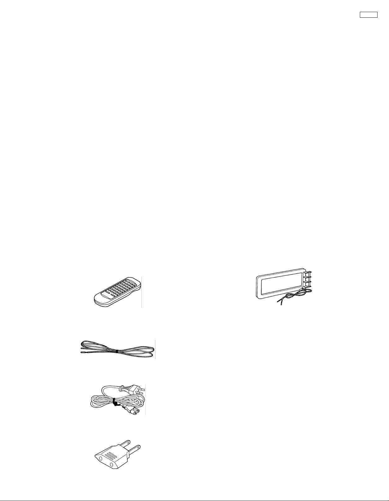
4 Accessories
Remote Control
Transmitter
FM indoor antenna
AC mains lead
AM Loop antenna
Power plug adapter
3
SA-AK52
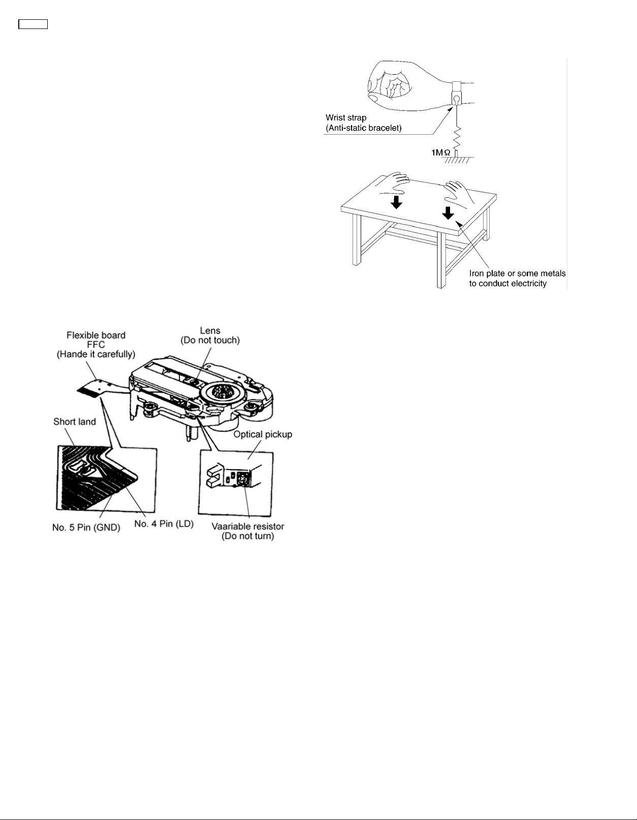
5 Handling Precautions For Traverse Deck
The laser diode in the traverse deck (optical pickup) may break
down due to potential difference caused by static electricity of
clothes or human body.
So, be careful of electrostatic breakdown during repair of the
traverse deck (optical pickup).
● Handling of traverse deck (optical pickup)
1. Do not subject the traverse deck (optical pickup) to
static electricity as it is extremely sensitive to electrical
shock.
2. The short land between the No.4 (LD) and No.5 (GND)
pins on the flexible board (FFC) is shorted with a solder
build-up to prevent damage to the laser diode.
To connect to the PC board, be sure to open by
removing the solder build-up, and finish the work
quickly.
3. Take care not to apply excessive stress to the flexible
board (FFC board).
4. Do not turn the variable resistor (laser power
adjustment). It has already been adjusted.
Caution when Replacing the Traverse Deck :
The traverse deck has a short point shorted with solder to
protect the laser diode against electrostatics breakdown. Be
sure to remove the solder from the short point before
making connections.
● Grounding for electrostatic breakdown prevention
1. Human body grounding
Use the anti-static wrist strap to discharge the static
electricity from your body.
2. Work table grounding
Put a conductive material (sheet) or steel sheet on the
area where the traverse deck (optical pickup) is placed,
and ground the sheet.
Caution :
The static electricity of your clothes will not be grounded
through the wrist strap. So, take care not to let your
clothes touch the traverse deck (optical pickup).
4
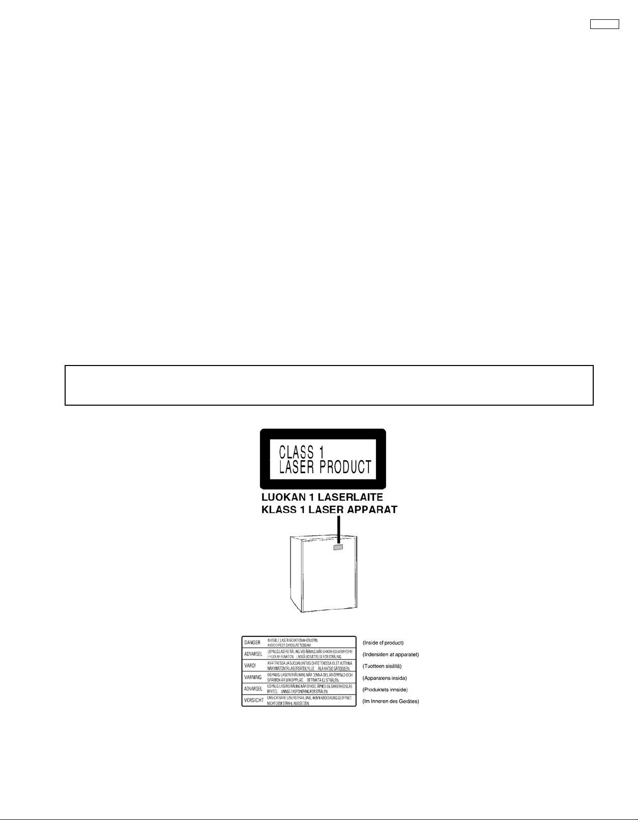
6 Precaution of Laser Diode
Caution :
This product utilizes a laser diode with the unit turned "ON", invisible laser radiation is emitted from the pick up lens.
Wavelength : 780 nm
Maximum output radiation power from pick up : 100 µW/VDE
Laser radiation from pick up unit is safety level, but be sure the followings:
1. Do not disassemble the optical pick up unit, since radiation from exposed laser diode is dangerous.
2. Do not adjust the variable resistor on the pick up unit. It was already adjusted.
3. Do not look at the focus lens using optical instruments.
4. Recommend not to look at pick up lens for a long time.
ACHTUNG :
Dieses Produkt enthält eine Laserdiode. Im eingeschalteten Zustand wird unsichtbare Laserstrahlung von der Lasereinheit
abgestrahlt.
Wellenlänge : 780nm
Maximale Strahlungsleistung der Lasereinheit :100W/VDE
Die Strahlung an der Lasereinheit ist ungefährlich, wenn folgende Punkte beachtet werden:
1. Die Lasereinheit nicht zerlegen, da die Strahlung an der freigelegten Laserdiode gefährlich ist.
2. Den werkseitig justierten Einstellregler der Lasereinhit nicht verstellen.
3. Nicht mit optischen Instrumenten in die Fokussierlinse blicken.
4. Nicht über längere Zeit in die Fokussierlinse blicken.
SA-AK52
ADVARSEL: I dette a apparat anvendes laser.
CAUTION!
THIS PRODUCT UTILIZES A LASER.
USE OF CONTROLS OR ADJUSTMENTS OR PERFORMANCE OF PROCEDURES OTHER THAN THOSE SPECIFIED HEREIN MAY RESULT
IN HAZARDOUS RADIATION EXPOSURE.
Use of Caution Labels
■
5
SA-AK52
7 Operation Procedures
6
SA-AK52
7
SA-AK52
8 Operation Checks and Main Component Replacement
Procedures
“ATTENTION SERVICER”
Some chassis components may have sharp edges.
Be careful when disassembling and servicing.
This section describes procedures for checking the operation of the major printed circuit boards and replacing the
1.
main components.
For reassembly after operation checks or replacement, reverse the respective procedures.
2.
Special reassembly procedures are described only when required.
Select items from the following index when checks or replacement are required.
3.
Contents
Disassembly and assembly main unit
•
1. Checking of the Main, Panel, Deck and Power P.C.B.
Main Component Replacement Procedures
•
1. Replacement of the Traverse Deck.
2. Replacement of the Power Amplifier IC.
Disassembly and assembly of the Traverse Unit
•
Disassembly and assembly of the Disc Tray
•
Warning:
This product uses a laser diode. Refer to caution statement Precaution of Laser Diode.
ACHTUNG:
Die Lasereinheit nicht zerlegen.
Die Lasereinheit darf nur gegen eine vom Hertsteller spezifizierte Einheit ausgetauscht werden.
8
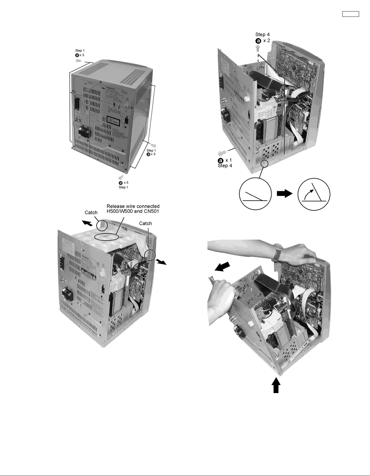
8.1. Disassembly and assembly main unit
Step 1 Remove 3 screws each side and 5 screws at rear panel.
Step 2 Remove the Top Cabinet
SA-AK52
Step 3 Remove T-bracket.
Step 4 Remove 2 screws each side of the inner chassis and a
screw at the rear panel. Turn locating pin 90°.
(Locating pin need not have to be bent back).
Step 5 Release the wires CN 300, 301, 302, 304 and 309.
Remove rear panel by pulling backward and lift rear panel assy
off.
Remove Front Panel
9
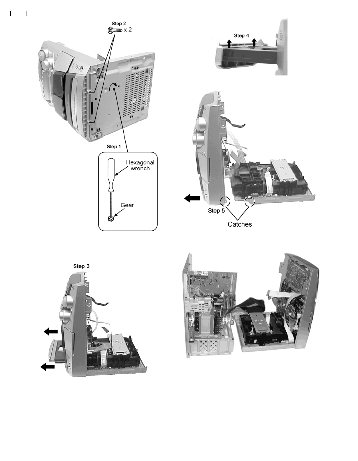
SA-AK52
Step 4 : Remove the CD lid in the direction of the arrow.
Step 1 : Use a hexagonal wrench and turn clockwise to release
the tray.
Step 2 : Remove the 2 screws.
Step 3 : Push the CD tray in the direction shown above.
Step 5 : Release the two catches shown above to remove the
front cabinet from the CD Traverse Unit.
Separated front and rear panel assy.
Removal of Inner bracket.
10
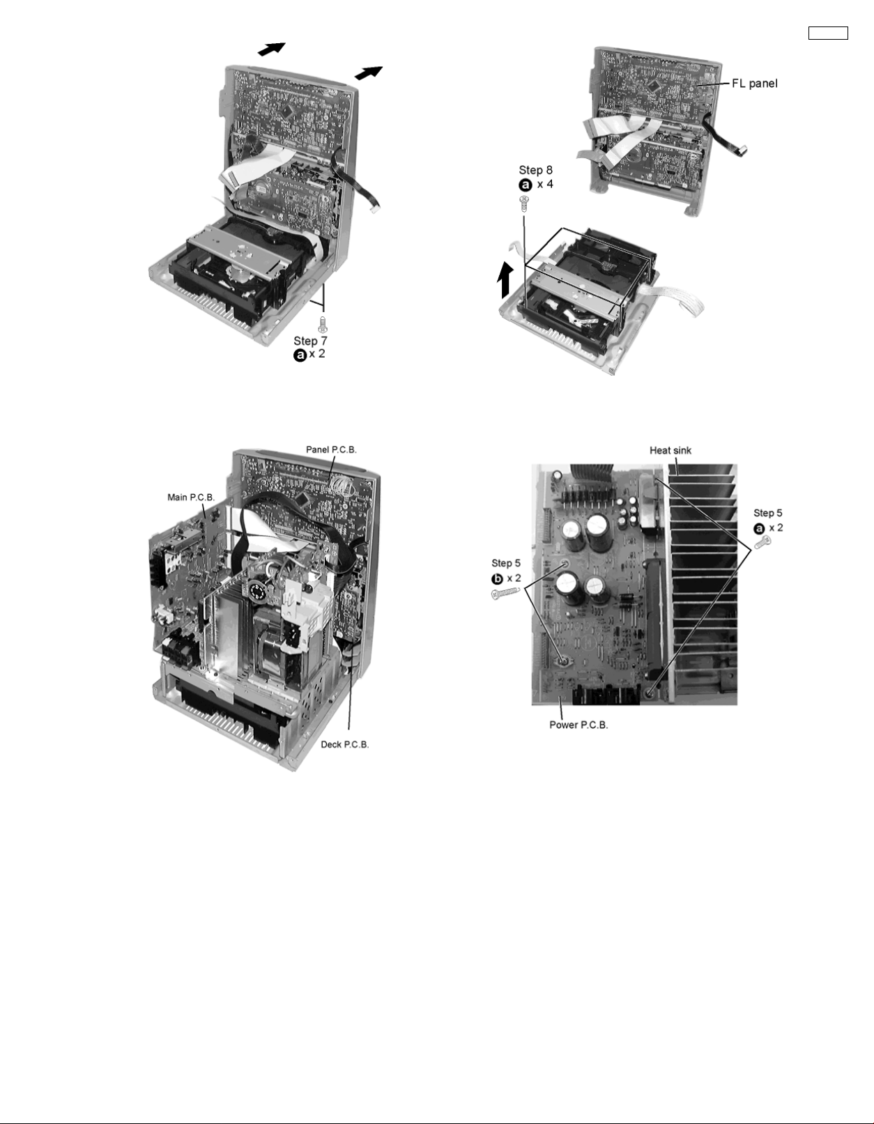
Step 7 Remove 2 screws from bottom and 2 screw beside
inner bracket to push forward to release the front panel.
Step 8 To release inner bracket, remove 4 screws.
8.1.1. Checking for Panel, Main and Deck P.C.B.
SA-AK52
Step 1 Remove 2 screws each side.
11
SA-AK52
8.1.2. Checking for Power P.C.B.
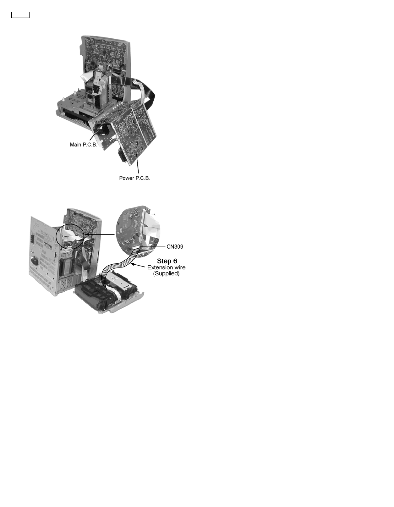
8.1.3. For Live Troubleshooting Procedure
Step 6 : Reconnect all connectors.
Step 7 : Use extension 14pin FFC wire for CN309.
Step 8 : Supply power for troubleshooting.
12

8.2. Main Component Replacement Procedures
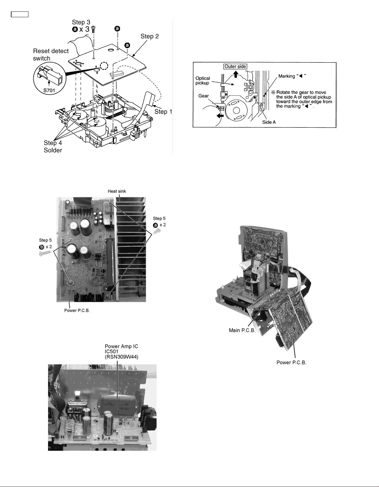
8.2.1. Replacement of the Traverse Deck
SA-AK52
Step 1
Step 1 - Step 4
Unit’ (
Follow the procedures in ‘Disassembly of the Traverse
).
Step 3
Servo P.C.B.
Step 4
the 3 pins. Then remove the Traverse Deck.
Desolder the 4 legs of the 2 motors and pull out the
Widen the 3 bosses with a flat screwdriver and pull out
Step 5
• Removal of the flexible cable. Push the top of the connector
Note:
Insert a short pin into the flexible cable for traverse unit.
•
Step 1
Step 2
assembly.
Remove the flexible cable CN701.
in the direction of the arrow 1, and then pull out the flexible
cable in the direction of the arrow 2.
Installation of the CD servo P.C.B. after replacement
Connect the FFC board.
Install the CD servo P.C.B. in the traverse deck
13
SA-AK52
8.2.2. Replacement of the Power Amplifier IC
Step 1 Follow the procedures in ‘Checking Procedure for each
major P.C.B.’ ( Step 1 - Step 6 ).
Note:
Before installing the CD servo P.C.B., move the optical pickup
towards the outer edge from the marking (black triangle).
[Otherwise, the reset detect switch (S701) mounted on the CD
servo P.C.B. may be damaged.]
Step 4 Remove the wires at CN302, CN303 and CN304 and
pull out the Main PCB.
Step 5 Remove the 4 screws fixed to the Power Amplifier IC.
Step 6 Unsolder the terminals of Power Amp IC and replace
the respective component.
14
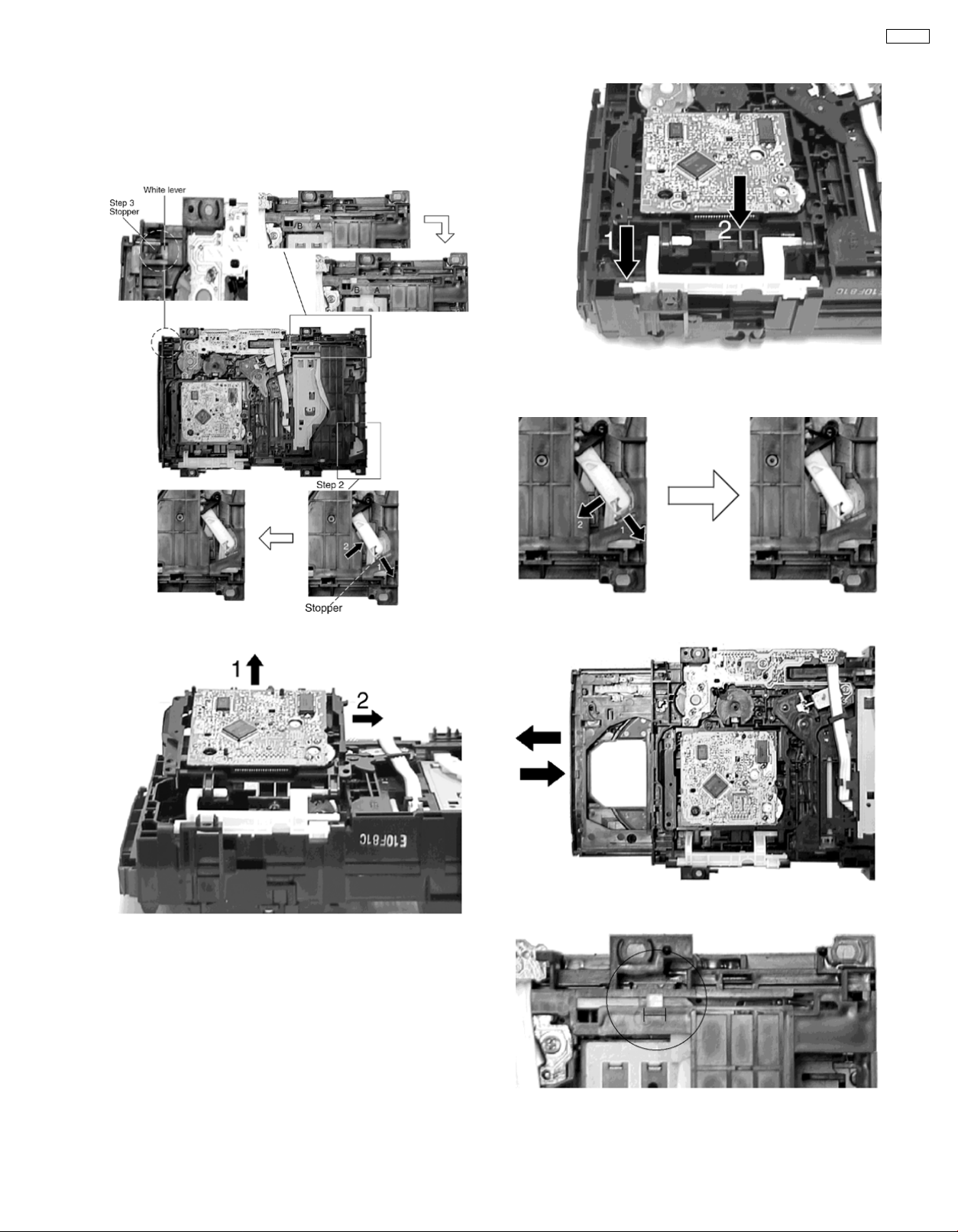
8.3. Disassembly and assembly of the Traverse Unit
Step 1 Push the lever from position A to B.
Step 2 Pull the stopper (black) in the direction of arrow 1 and
push the lever in the direction of arrow 2.
Step 3 Push the stopper (black) down until the white lever eject
out.
Step 3 Pull the stopper in the direction of arrow 1 and release
the lever in the direction of arrow 2 as shown.
SA-AK52
Step 4 Lift up the traverse unit and slide out the unit as shown.
• Replacement of Traverse Unit
Step 1 Place the traverse unit as shown.
Step 2 Press in the lever shaft in the direction of arrow 1 as
shown and push the traverse unit into the position in the
direction of arrow 2.
Step 4 Pull out the tray half way and push it back fully.
Step 5 Push the lever to the initial position indicated ‘|---|’.
15
SA-AK52
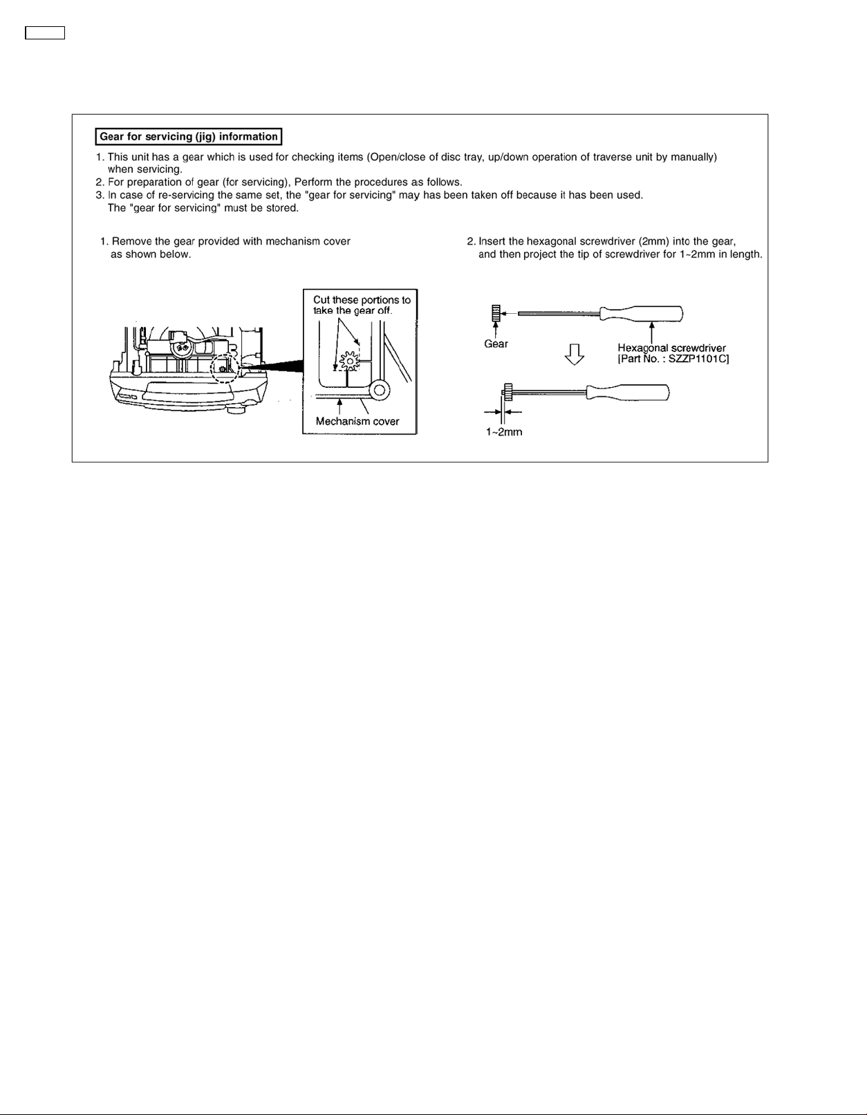
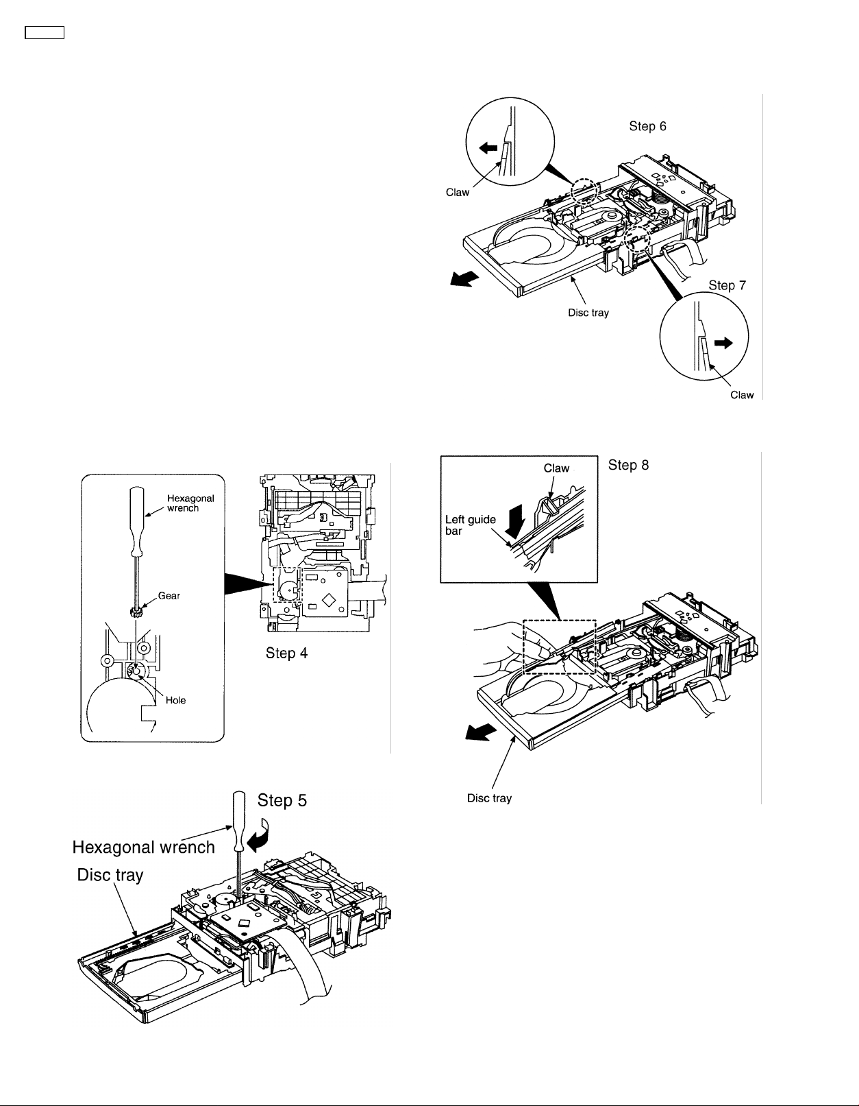
8.4. Disassembly and assembly of the Disc Tray
(clockwise), and then open the disc tray fully.
Step 2 With lifting the claw in the direction of arrow 1, draw the
clamp SW P.C.B. in the direction of arrow 2.
Step 3 Remove the mechanism cover.
Step 4 Insert the gear with hexagonal wrench into the hole.
Step 6 Upset the CD changer unit again.
Step 7 Release both the claws, and then draw the disc tray.
Step 5 Rotate the hexagonal wrench in the direction of arrow
Step 8 With forcing the left guide bar manually because the left
guide bar interferes with claw, draw the disc tray.
• Installation of the disc tray after replacement
16
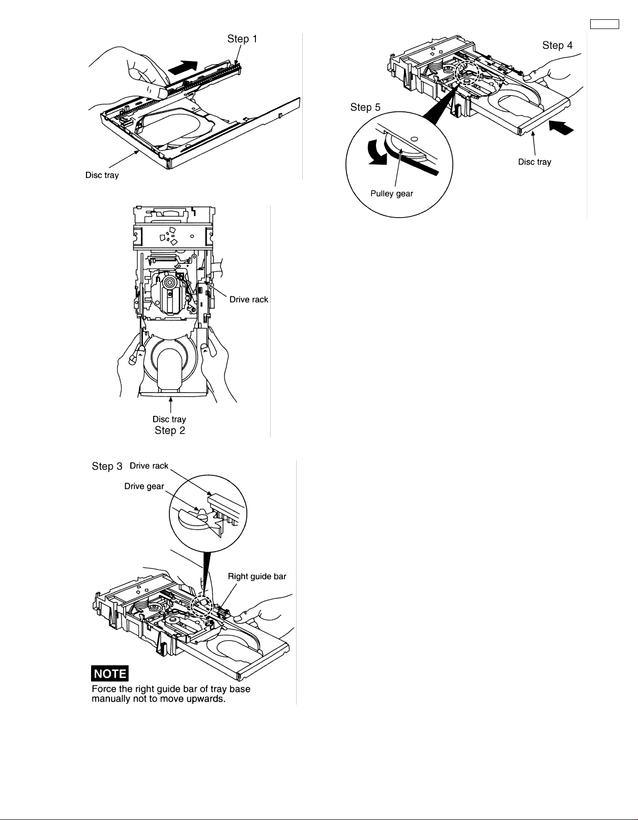
Step 1 Slide the drive rack fully in the direction of the arrow.
SA-AK52
Step 4 Holding the disc tray manually, rotate the pulley gear in
the direction of arrow.
Step 5 Rotate the gear 5 or 6 times manually, and then push
the disc tray.
Step 2 Holding the drive rack, not to move, install the disc tray.
Step 3 Align the drive rack with the drive gear.
17
SA-AK52
9 Self-Diagnostic Function
9.1. Self-diagnostic display
This unit is equipped with a self-diagnostic display function which, if a problem occurs, will display an error code corresponding to
the problem.
Use this function when performing maintenance on the unit.
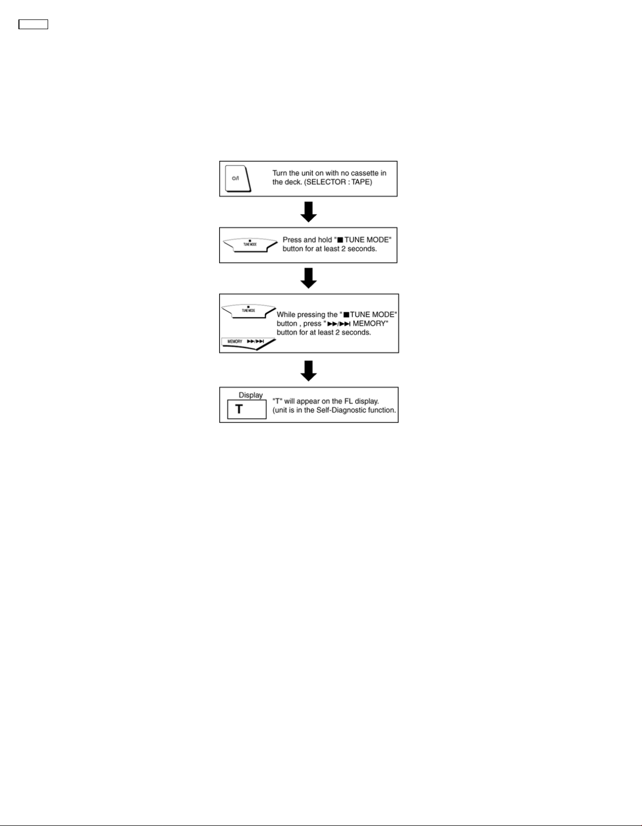
9.2. How to enter the Self-Diagnostic Function
9.3. Cassette Mechanism Test (For error code H01, H02, H03, F01, F02)
1. Press “TAPE, DECK 1/2” to select Deck 2.
2. Load a cassette tape with the erasure prevention tab, remove from left side only and close the cassette holder.
3. Press “FAST FORWARD MEMORY” (Tape will be stop after 2 seconds)
4. Load a cassette tape with the erasure prevention tab, remove from right side only and close the cassette holder.
5. Press “REVERSE FM MODE/BP” (Tape will be stop after 2 seconds)
6. Load a pre-recorded tape with both side record tabs intact and close the cassette holder.
7. Press “PLAY/TUNE/TIME ADJ UP” (After TPS function, tape will stop automatically)
8. Press “REC/STOP” (Tape will not move)
9. Press “STOP/TUNE MODE” to indicate Error code.
• If several problem exist, error code will change each time when “■ /TUNE MODE” is pressed.
(e.g. H01 → H03 → F01 .....etc.)
10. Press “TAPE, DECK 1/2” to select Deck 1.
11. Repeat step 2 to 9 to test Deck 1. (Tape Deck 1 will not check H02 because of no recording function)
9.4. CD Mechanism Test (F15, F26, F16, F17, F27, F28, F29, H15, F75)
1. Press “CD”.
2. Press “OPEN/CLOSE (1)” and place a CD.
3. Press “OPEN/CLOSE (1)” to close the tray.
4. Press “OPEN/CLOSE (5)” and wait until the tray is open.
5. Press “OPEN/CLOSE (1)” and remove the CD.
6. Press “OPEN/CLOSE (1)” to close the tray.
18
7. Press “■/TUNE MODE” to indicate Error Code.
• If several problem exist, error code will change each time when “■/TUNE MODE” is pressed. (e.g. F15 → F26 → F16 ....etc).
9.5. To clear all Error code
1. Press “STOP/TUNE MODE” button for 5 seconds.
2. FL indicator shows “CLEAR” for 1 second and change to “T”.
9.6. How to get out from Self-Diagnostic function
1. Press “Power” button OFF.
9.7. Power Amplifier Failure (F61)
1. When power amplifier fail, F61 will indicate automatically.
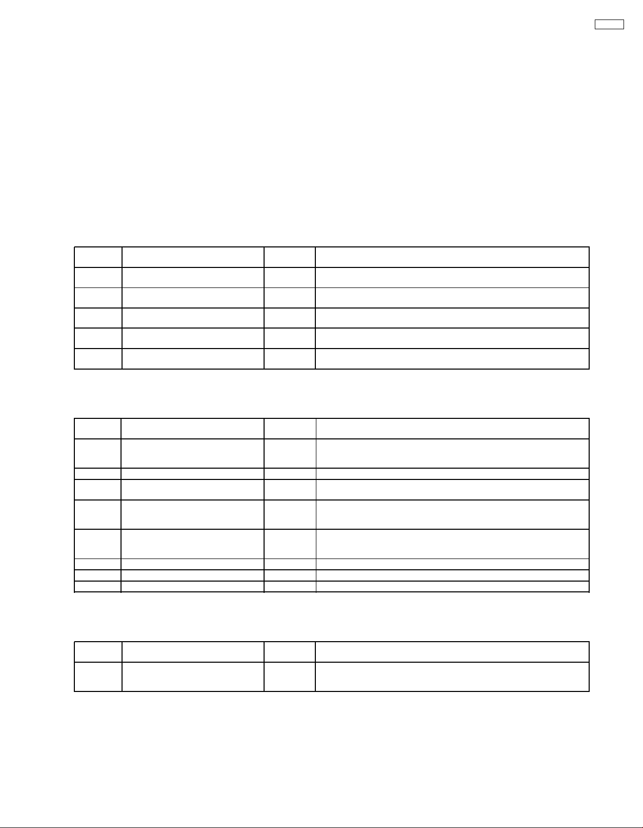
10 Description of Error Code
10.1. Error detection for Cassette Mechanism block
SA-AK52
No. Error Error
1 MODE SW
detection error
2 REC INH SW
detection error
3 HALF SW
detection error
4 Reel Pulse
detection error
5 TPS abnormal F02 Cassette deck will not perform TPS function.
Display
H01 Faulty operation of cassette mechanism.
H02 Recording not possible.
H03 Playback cannot perform.
F01 The tape advances slightly and then stops.
Problem condition
Faulty contact or short-circuit of mechanism mode switch (S951, S971).
Faulty contact or short-circuit of REC INH switch (S974, S975).
Faulty contact or short-circuit of HALF siwtch (S952, S972).
Faulty reel pulse, faulty hole detect IC (IC951, IC971).
Faulty playback EQ/recording amplifier IC (IC101).
10.2. Error detection for CD/Changer block
No. Error Error
1 REST SW detection error F15 CD does not function.
2 CD tray opens automatically F16 CLAMP switch (S4) NG (Check & Replace)
3 Does not startup when [PLAY]
button is pressed
4 Transmission error between CD
servo LSI and micon
5 Startup fails even when you
insert CD or the selected disc tray
does not open
6 Cannot insert CD F28 Tray 1 detect switch NG (Check & Replace)
7 Cannot eject CD F29 Check if disc is stuck. Tray 2 detect switch NG (Confirm & Replace)
8 The CD tray closes H15 CD disc tray detect switch NG (S3) (Check & Replace)
Display
F17 BOTTOM switch (S5) NG (Check & Replace)
F26 CD does not function.
F27 Tray 1 detect switch or Tray 2 detect switch NG (Check & Replace)
Problem condition
This error occurs when the Optical Pick Up REST SW (S701) is not
detected within the specified time (about 8 seconds)
This error occurs when the POWER is ON for the CD block and an error
is detected after the transmission has started.
10.3. Power Supply related error detection
No. Error Error
1 POWER AMP
output abnormal
Display
F61 When POWER is switched on, power become off automatically.
Problem condition
During normal operation, if DC DET become L, PCNT shall become
L and the error display on the left shall be displayed. (IC501)
19
SA-AK52
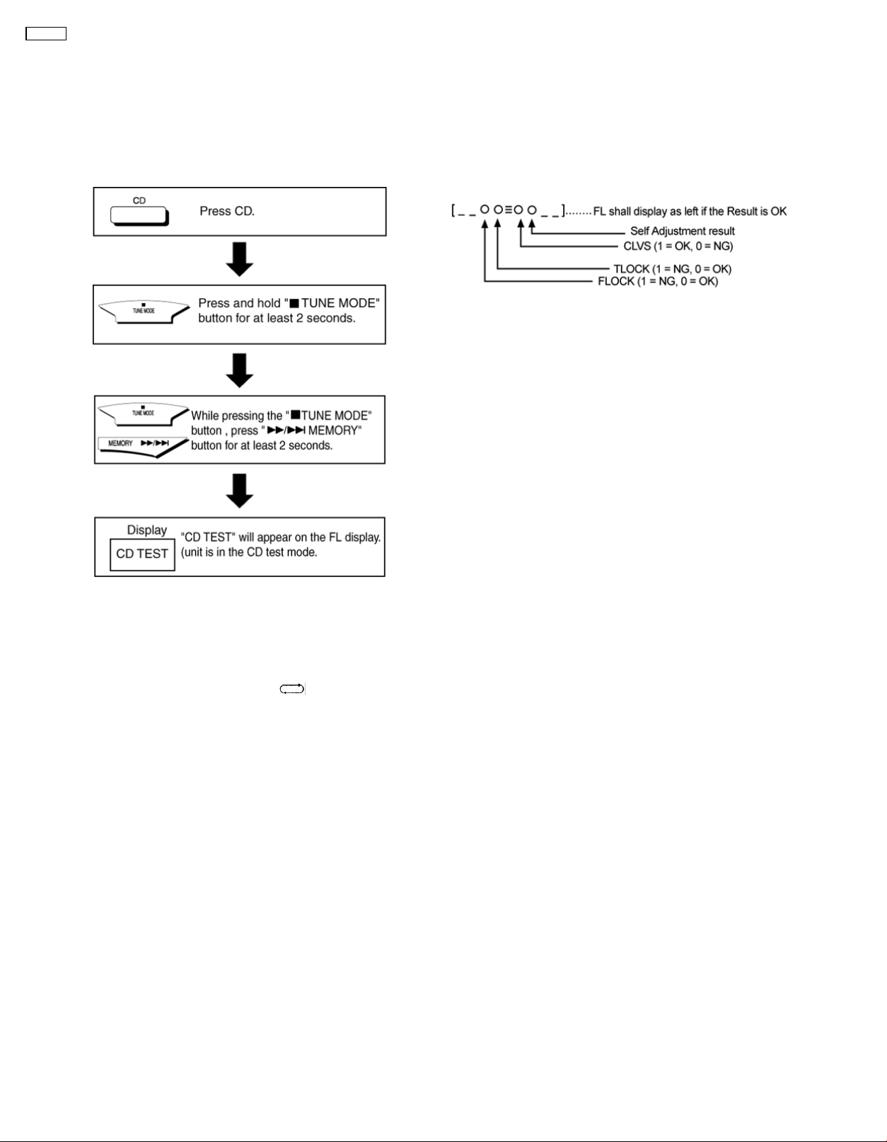
11 CD Test Mode Function
This CD test mode is provided to check CD unit without
connecting to changer loading mechanism. This mode shall
operate CD PLAY with CD unit being connected only and CD
Automatic Alignment result is shown on FL display.
11.1. How to set CD test mode
11.2. CD Automatically Adjustment
result indication
Under CD test mode, pressing the numeric key ‘0’ on the
remote controller will display the auto adjustment result.
FLOCK, TLOCK and CLVS status shall be shown as below:
During the above display, executing CD PLAY will display auto
adjustment result for CD PLAY mode.
12 Measurements and Adjustments
12.1. Cassette Deck Section
• Measurement Condition
− Reverse-mode selector switch:
− Tape edit: NORMAL
− Record timer: OFF
− Make sure head, capstan and press roller are clean.
− Judgeable room temperature 20 ± 5 °C (68 ± 9°F)
• Measuring instrument
− EVM (Electronic Volmeter)
− Digital quency counter
• Test Tape
− Head azimuth adjustment (8 kHz, -20 dB); QZZCFM
− Tape speed gain adjustment (3 kHz, -10 dB);
QZZCWAT
− Playback gain adjustment (315 Hz, 0 dB); QZZCFM
− CrO2 tape, QZZCRX
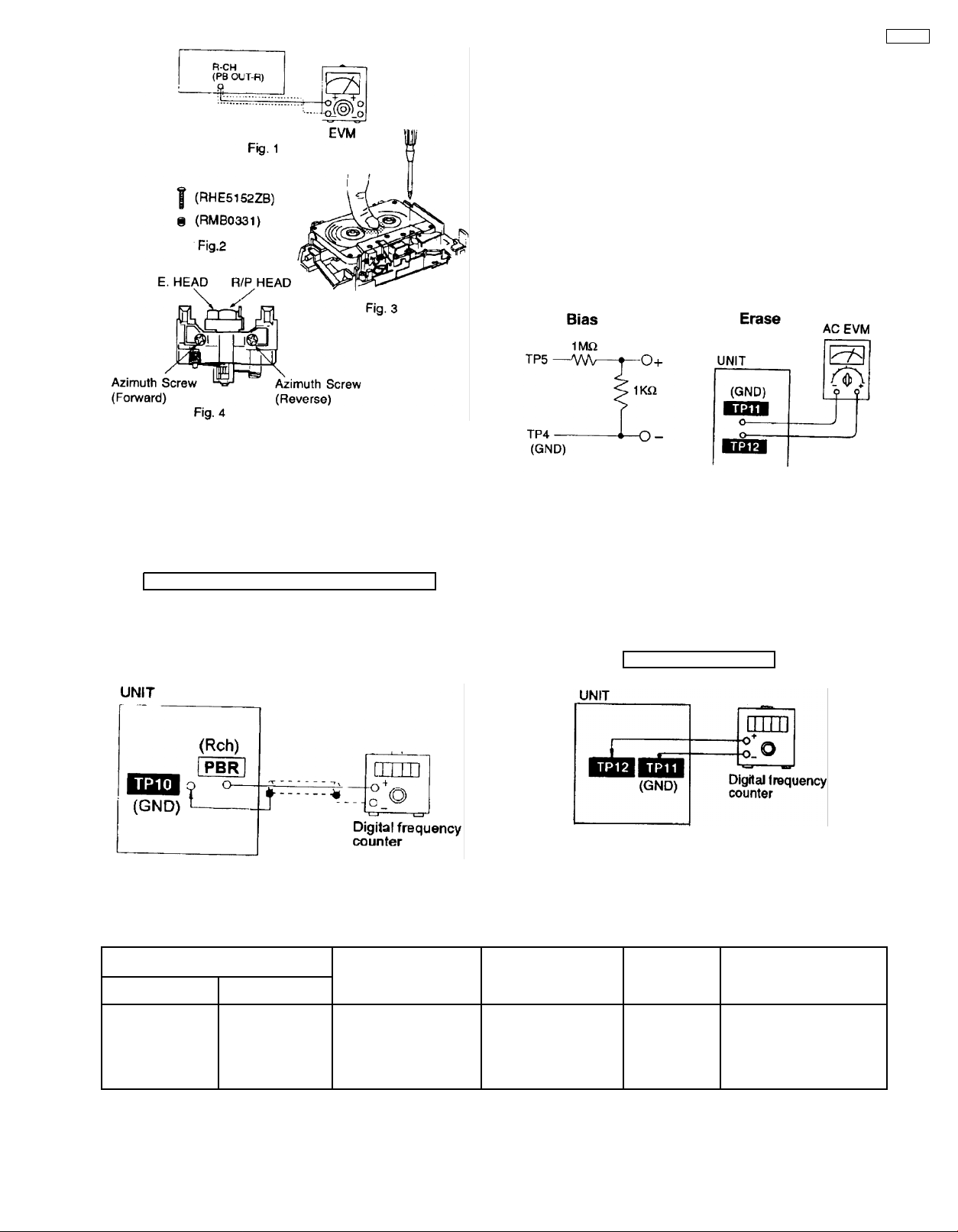
12.1.1. Head Azimuth Adjustment (Deck
1/2)
wish to readjust the head azimuth without replacing the
acrews and springs, a fine adjustment to the azimuth screw
and spring.
• Please remove the screw-locking bond left on the head
base when replacing the azimuth screw.
• If you wish to readjust the head azimuth, be sure to adjust
with adhering the cassette tape closely to the mechanism
by pushing the center of cassette tape with your finger.
(shown in Fig. 3)
1. Playback the azimuth adjustment portion (8 kHz, -20dB) of
the test tape (QZZCFM) in the forward play mode. Vary the
azimuth adjustment screw until the output of the R-CH (PB
OUT-R) are maximized.
2. Perform the same adjustment in the reverse play mode.
3. After the adjustment, apply screwlock to the azimuth
adjusting screw.
Caution:
• Please replace both azimuth adjustment screw
(RHE5152ZB) and springs (RM0331) simultaneously when
readjusting the head azimuth. (shown in Fig. 2) Even if you
20
12.1.2. Tape Speed Adjustment (Deck 1/2)
1. Set the tape edit button to “NORMAL” position.
2. Insert the test tape (QZZCWAT) to DECK 2 and playback
(FWD side) the middle portion of it.
3. Adjust Motor VR (DECK 2) for the output value shown
below.
Adjustment target: 2940~3060 Hz (NORMALspeed)
4. After alignment, assure that the output frequency of the
DECK 2 REV and DECK 1 FWD are within ±45Hz and ±60
Hz respectively of the value of the output frequency of
DECK 2 FWD.
SA-AK52
12.1.3. Bias and Erase Voltage Check
1. Set the unit “AUX” position.
2. Insert the Normal blank tape (QZZCRA) into DECK 2 and
the unit to “REC” mode (use “● REC/STOP” key).
3. Measure and make sure that the output is within the
standard value.
4. Insert the CrO2 tape (QZZCRX).
5. Repeat step 2 and 3.
Bias voltage for Deck 2 14 ± 4mV (Normal)
Standard value) 17 ± 5mV (CrO2)
Erase voltage for Deck 2 more than 80mV (Normal)
more than 90mV (CrO2)
12.1.4. Bias Frequency Adjustment (Deck
1/2)
1. Set the unit to “AUX” position.
2. Insert the Normal blank tape (QZZCRA) into DECK 2 and
set the unit to “REC” mode (● use “REC/STOP” key).
3. Adjust L1002 so that the output frequency is within the
standard value.
Standard Value: 97 ±8 kHz
12.2. Tuner Section
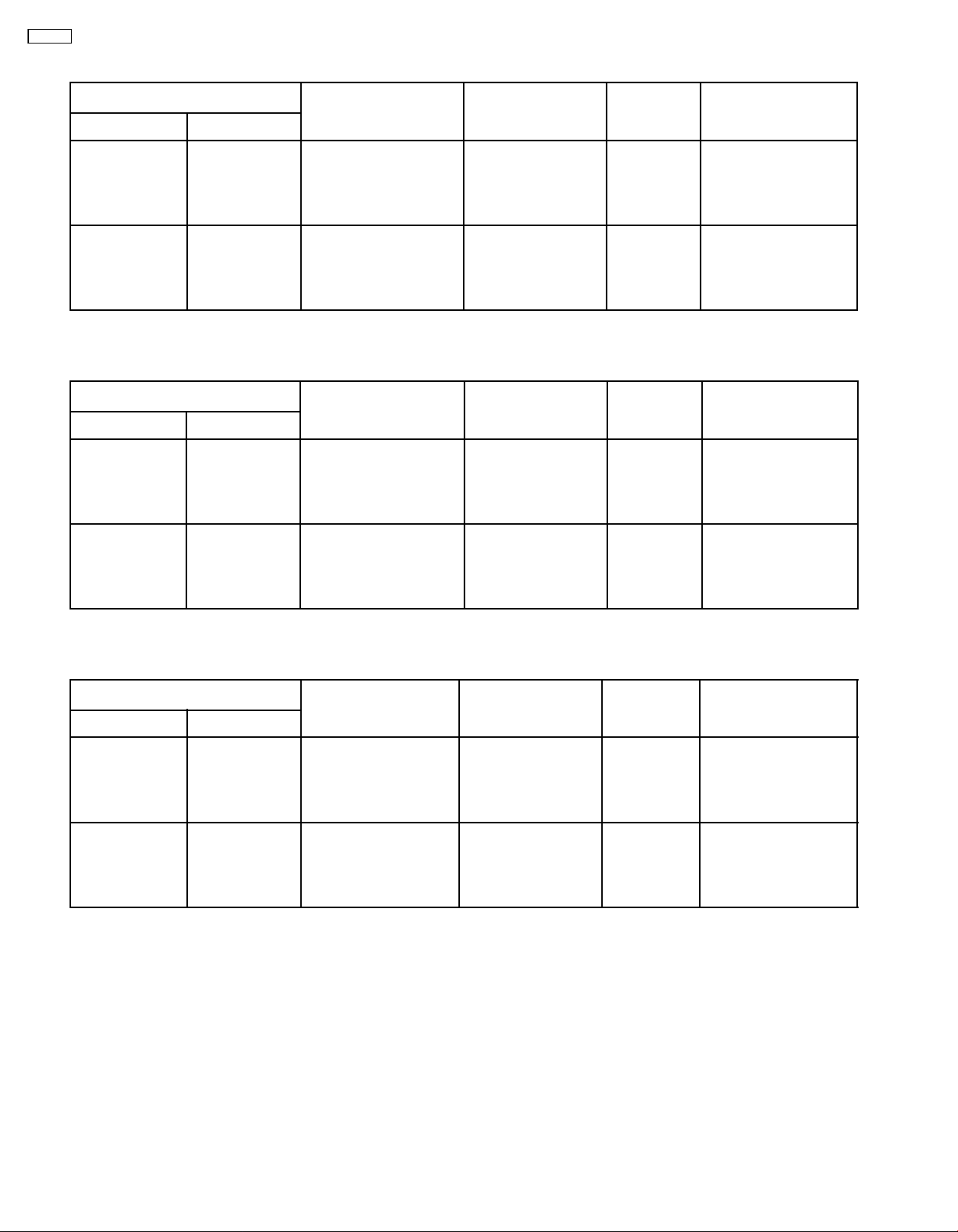
12.2.1. AM-IF Alignment
SIGNAL GENERATOR OR SWEEP
CONNECTIONS FREQUENCY
Fashion a loop of
several turns of wire
and radiate a signal
into the loop ant. of
receiver.
GENERATOR
450 kHz 30% Mod.
at 400Hz.
RADIO DIAL SETTING INDICATOR
Point of non-interference
(on/about 600 kHz)
(ELECTRONIC
VOLTMETER
OSCILLOSCOPE)
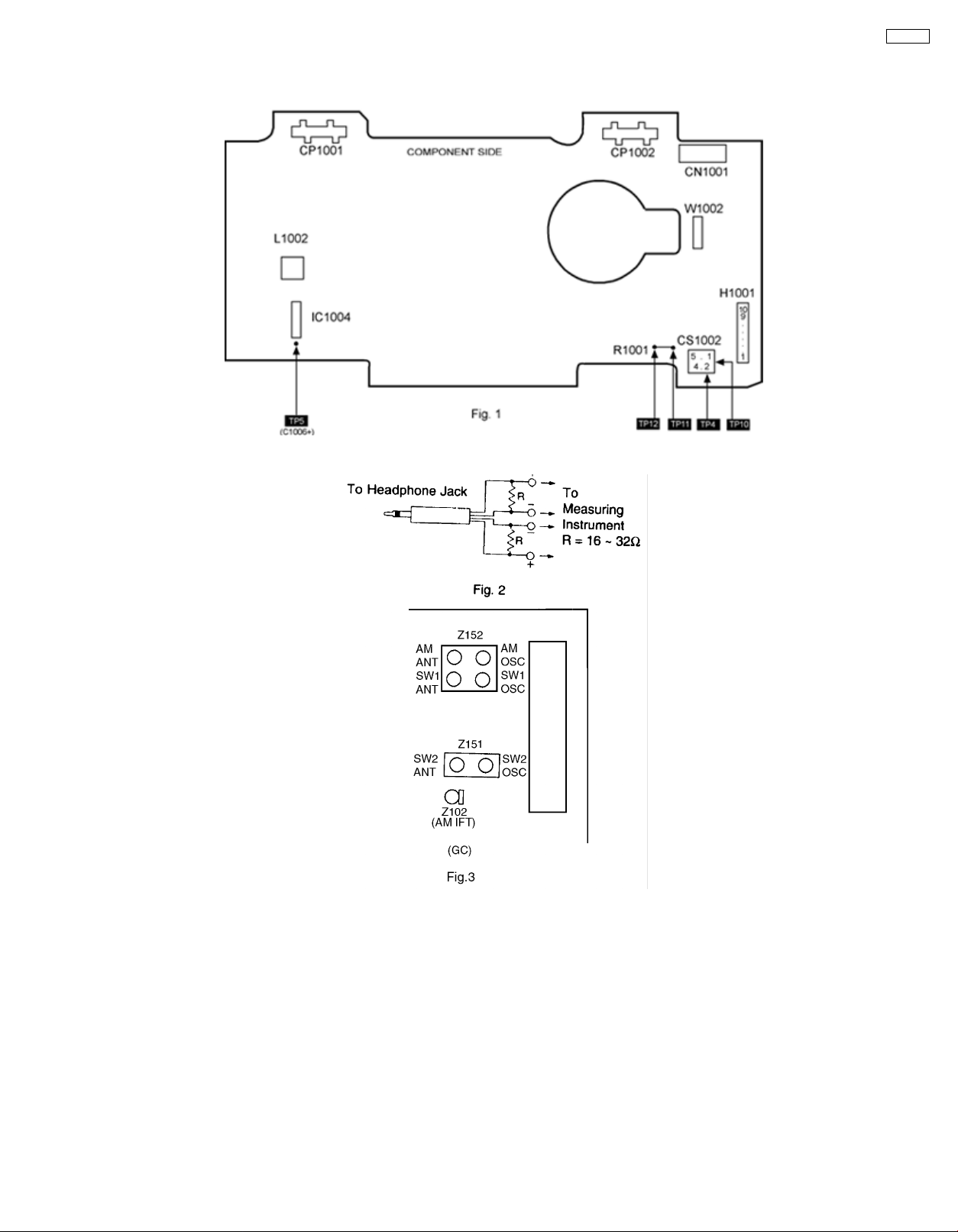
Headphones Jack (32Ω)
Fabricate the plug as
shown in Fig. 2 and then
connect the lead wires of
the plug to the
measuring instrument.
21
ADJUSTMENT
(Shown in
Fig.3)
Z102 (AM IFT) Adjust for maximum output.
REMARKS
SA-AK52
12.2.2. AM-RF Alignment
SIGNAL GENERATOR OR SWEEP
CONNECTIONS FREQUENCY
Fashion a loop of
several turns of wire
and radiate a signal
into the loop ant. of
receiver.
Fashion a loop of
several turns of wire
and radiate a signal
into the loop ant. of
receiver.
GENERATOR
522 kHz Tuning capacitor fully closed Headphones Jack (32Ω)
603 kHz Tuning to signal Headphones Jack (32Ω)
RADIO DIAL SETTING INDICATOR
12.2.3. SW1-RF Alignment (GC)
SIGNAL GENERATOR OR SWEEP
CONNECTIONS FREQUENCY
Fashion a loop of
several turns of wire
and radiate a signal
into the loop ant. of
receiver.
Fashion a loop of
several turns of wire
and radiate a signal
into the loop ant. of
receiver.
GENERATOR
3.2 MHz Tuning capacitor fully closed Headphones Jack (32Ω)
3.2 MHz Tuning to signal Headphones Jack (32Ω)
RADIO DIAL SETTING INDICATOR
(ELECTRONIC
VOLTMETER
OSCILLOSCOPE)
Fabricate the plug as
shown in Fig. 2 and then
connect the lead wires of
the plug to the
measuring instrument.
Fabricate the plug as
shown in Fig. 2 and then
connect the lead wires of
the plug to the
measuring instrument.
(ELECTRONIC
VOLTMETER
OSCILLOSCOPE)
Fabricate the plug as
shown in Fig. 2 and then
connect the lead wires of
the plug to the
measuring instrument.
Fabricate the plug as
shown in Fig. 2 and then
connect the lead wires of
the plug to the
measuring instrument.
ADJUSTMENT
(Shown in
Fig.3)
Z152 (GC),
(AM OSC Coil)
Z152 (GC),
(AM ANT Coil)
ADJUSTMENT
(Shown in
Fig.3)
Z152
(SW1 OSC
Coil)
Z152
(SW1 ANT Coil)
REMARKS
Adjust for maximum output.
Adjust for maximum output.
REMARKS
Adjust for maximum output.
Adjust for maximum output.
12.2.4. SW2-RF Alignment (GC)
SIGNAL GENERATOR OR SWEEP
CONNECTIONS FREQUENCY
Fashion a loop of
several turns of wire
and radiate a signal
into the loop ant. of
receiver.
Fashion a loop of
several turns of wire
and radiate a signal
into the loop ant. of
receiver.
GENERATOR
9.4 MHz Tuning capacitor fully
9.4 MHz Tuning to signal Headphones Jack (32Ω)
RADIO DIAL SETTING INDICATOR
closed
(ELECTRONIC
VOLTMETER
OSCILLOSCOPE)
Headphones Jack (32Ω)
Fabricate the plug as
shown in Fig. 2 and then
connect the lead wires of
the plug to the
measuring instrument.
Fabricate the plug as
shown in Fig. 2 and then
connect the lead wires of
the plug to the
measuring instrument.
ADJUSTMENT
(Shown in
Fig.3)
Z151
(SW2 OSC Coil)
Z151
(SW2 ANT Coil)
REMARKS
Adjust for maximum output.
Adjust for maximum output.
22
12.3. Alignment Points
Cassette Deck section
Tuner section
SA-AK52
23
SA-AK52
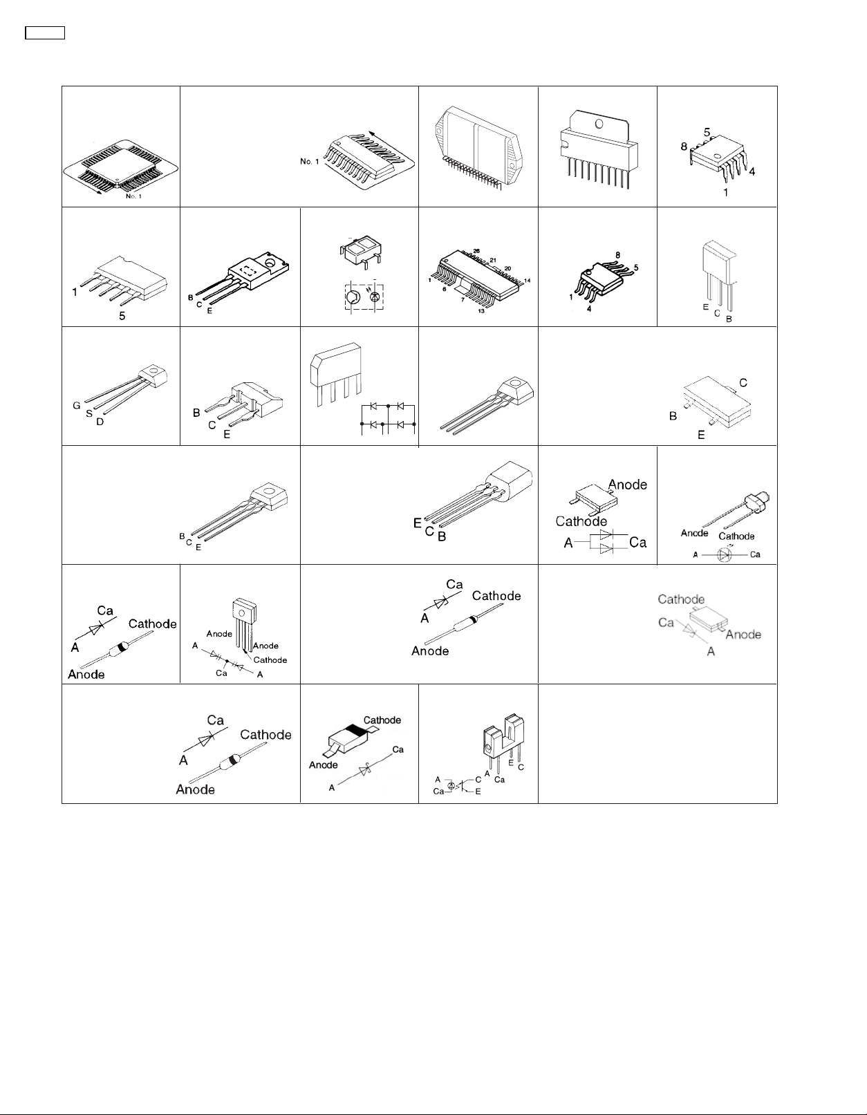
13 Illustration of IC’s, Transistors and Diodes
M38B79MFA053(100P)
BH3874AKS2 (64P)
MN662790RSC (80P)
BA7755A
2SK544F-AC
2SA933SSTA
2SC2787FL1TA
2SD2144STA
KTC3199GRTA
RVTDTC143EST
2SC2786MTA
BU2090AF-E2 (16P)
LA1833NMNTLM (24P)
LC72131MDTRM (20P)
AN7348STA-E1 (24P)
BA4558FE2 (8P)
AN8885SBE1 (28P)
TC4052BFNELM (16P)
KTC2026
KTA1046
2SD1859QRTV2
2SB1238QRTV2
0N2180RLC1
2
1
4
2
1
KBP152G4R5
4
3
2
1
123 4
KTA12710YTA
KTC3205YTA
2SB621ARSTA
KRC101MTA
KTA1504GRTA
KTD1146YTA
KTC32030YTA
RSN309W44B
TA7291P
M5218AP
93LC46B
1
26
AN8739SBE2
3
3
4
KRA102MTA
KRC103MTA
KRC102MTA
2SC1740SSTA
1
KIA4558FEL
2SA1037AKSTX
2SC2412KT96R
KRA102STA
KTC3875GRTA
10
2SC2058SPTA
2SA1309ARTA
DTA114EKA146
DTC143XKA146
KRC111STA
KTD1304TA
KRC102STA
B
C
E
KRA102STA
DAP202KT146
SLI325URCT31
SLR325MCT31W
SLR325DCT31
1N5402BM21
RL1N4003S-P
1T3T
RVD1SS133TA
1SS291TA
MA165TA
MA700ATA
MA723TA
SVC211SPA-AL
MA4020LTA
MTZJ7R5ATA
MTZJ4R7BTA
MTZJ20BTA
MTZJ240TA
MA728TX
1SS355TE17
UDZSTE175R1B
UDZTE173R6B
MA8300MTX
UDZSTE177R5B
GP1S94
24
 Loading...