

Panasonic SAAK-52 Service manual

file:///C|/Documents%20and%20Settings/Moi/Mes%20documents/PANASONIC%20SA-AK52EE/SA-AK52EE/SVC/svcml.html
Table Of Contents
COVER
1 Before Repair and Adjustment
2 Protection Circuitry
3 Accessories
4 Handling Precautions For Traverse Deck
5 Precaution of Laser Diode
6 Operation Procedures
7 Disassembly and Main Component Replacement Procedures
7.1 Disassembly Procedure For Each Major P.C.B. Checking
7.1.1 Checking of the Main, Transformer, Panel and Deck P.C.B.
7.1.2 Checking of the Power P.C.B.
7.2 Main Component Replacement Procedures
7.3 Disassembly and assembly of the Traverse Unit
7.4 Disassembly and assembly of the Disc Tray
8 Self-Diagnostic Function
8.1 Self-diagnostic display
8.2 How to enter the Self-Diagnostic Function
8.3 Cassette Mechanism Test (For error code H01, H02, H03, F01, F02)
8.4 CD Mechanism Test (F15, F26, F16, F17, F27, F28, F29, H15)
PV
file:///C|/Documents%20and%20Settings/Moi/Mes%2.../PANASONIC%20SA-AK52EE/SA-AK52EE/SVC/svcml.html (1 of 4)03/08/2005 21:38:06

file:///C|/Documents%20and%20Settings/Moi/Mes%20documents/PANASONIC%20SA-AK52EE/SA-AK52EE/SVC/svcml.html
8.5 To clear all Error code
8.6 How to get out from Self-Diagnostic function
8.7 Power Amplifier Failure (F61)
9 Description of Error Code
9.1 Error detection for Cassette Mechanism block
9.2 Error detection for CD/Changer block
9.3 Power Supply related error detection
10 CD Test Mode Function
10.1 How to set CD test mode
10.2 CD Automatically Adjustment result indication
11 Measurements and Adjustments
11.1 Cassette Deck Section
11.1.1 Head Azimuth Adjustment (Deck 1/2)
11.1.2 Tape Speed Adjustment (Deck 1/2)
11.1.3 Bias and Erase Voltage Check
11.1.4 Bias Frequency Adjustment (Deck 1/2)
11.2 Tuner Section
11.2.1 AM-IF Alignment
11.3 Alignment Points
12 Illustration of IC’s, Transistors and Diodes
file:///C|/Documents%20and%20Settings/Moi/Mes%2.../PANASONIC%20SA-AK52EE/SA-AK52EE/SVC/svcml.html (2 of 4)03/08/2005 21:38:06

file:///C|/Documents%20and%20Settings/Moi/Mes%20documents/PANASONIC%20SA-AK52EE/SA-AK52EE/SVC/svcml.html
13 Terminal Function of IC’s
13.1 IC701 (AN8885SBE1) Servo Amplifier
13.2 IC702 (MN662790RSC) Servo Processor, Digital Signal Processor, Digital Filter, D/A
Converter
13.3 IC703 (AN8739SBE2) Focus Coil, Tracking Coil, Traverse Motor, Spindle Motor Drive
13.4 IC600 (M38B79MFA158) Microprocessor
14 Block Diagram
15 Schematic Diagram
16 Printed Circuit Board
17 Wiring Connection Diagram
18 Troubleshooting Guide
19 Parts Location and Replacement Parts List
19.1 Deck Mechanism (RAA3408)
19.1.1 Deck Mechanism Parts Location
19.1.2 Deck Mechanism Parts List
19.2 CD Loading Mechanism (RD-DAC026-S)
19.2.1 CD Loading Mechanism Parts Location
19.2.2 CD Loading Mechanism Parts List
19.3 Cabinet
19.3.1 Cabinet Parts Location
19.3.2 Cabinet Parts List
PV
file:///C|/Documents%20and%20Settings/Moi/Mes%2.../PANASONIC%20SA-AK52EE/SA-AK52EE/SVC/svcml.html (3 of 4)03/08/2005 21:38:06

file:///C|/Documents%20and%20Settings/Moi/Mes%20documents/PANASONIC%20SA-AK52EE/SA-AK52EE/SVC/svcml.html
19.4 Electrical Parts List
19.5 Packing Materials& Accessories Parts List
19.6 Packaging
file:///C|/Documents%20and%20Settings/Moi/Mes%2.../PANASONIC%20SA-AK52EE/SA-AK52EE/SVC/svcml.html (4 of 4)03/08/2005 21:38:06
file:///C|/Documents%20and%20Settings/Moi/Mes%20documents/PANASONIC%20SA-AK52EE/SA-AK52EE/SVC/s0000000000.html
Service Manual
TOP NEXT
ORDER NO. MD0104079C2
CD Stereo System
● SA-AK52EE
Colour
(S)... Silver Type
Area
(EE)... Russian& Ukraine
TAPE SECTION :
AR2 MECHANISM SERIES
CD SECTION :
RAE0152Z-3 TRAVERSE DECK SERIES
Specifications
AMPLIFIER SECTION
Power output
THD 10%
80Hz, both channels driven
(LOW)
115 W per channel (6Ω)
1 kHz, both channels driven
(High)
45 W per channel (6Ω)
Total Bi-Amp Power 160W per channel
file:///C|/Documents%20and%20Settings/Moi/Mes%20documents/PANASONIC%20SA-AK52EE/SA-AK52EE/SVC/s0000000000.html (1 of 3)03/08/2005 21:38:06

file:///C|/Documents%20and%20Settings/Moi/Mes%20documents/PANASONIC%20SA-AK52EE/SA-AK52EE/SVC/s0000000000.html
Input sensitivity
AUX 250 mV
Input Impedance
AUX
13 kΩ
FM TUNER SECTION
Frequency range 87.50 - 108.00 MHz (50 kHz steps)
Antenna terminal(s)
75Ω (unbalanced)
AM TUNER SECTION
Frequency range 522 - 1629 kHz (9 kHz steps)
Sensitivity
S/N 20 dB (at 999 kHz)
560μV/m
CASSETTE DECK SECTION
Track system 4 track, 2 channel
Heads
Record/playback Solid permalloy head
Erasure Double gap ferrite head
Motor DC servo motor
Recording system AC bias 100 kHz
Erasing system AC erase 100 kHz
Tape speed 4.8 cm/s
Frequency response (+3 dB, -6 dB at DECK OUT)
NORMAL (TYPE I) 35 Hz - 14 kHz
HIGH (TYPE II) 35 Hz - 14 kHz
S/N 50 dB (A weighted)
Wow and flutter 0.18% (WRMS)
Fast forward and rewind time Approx. 120 seconds with
C-60 cassette tape
CD SECTION
Sampling frequency 44.1 kHz
Decoding 16 bit linear
Beam source/wave length Semiconductor laser/780 nm
Number of channels Stereo
Frequency response 20 Hz - 20 kHz (+1, -2 dB)
Wow and flutter Below measurable limit
Digital filter 8 fs
D/A converter MASH (1 bit DAC)
GENERAL
Power supply AC 230 - 240 V, 50Hz
Power consumption 185 W
Power consumption in standby mode
0.4 W
Dimensions (W x H x D) 250 X 332 X 316mm
Mass 8.5 kg
SYSTEM
SC-AK52(EE) Music Center: SA-AK52(EE)
Speaker: SB-AK52(GC)
file:///C|/Documents%20and%20Settings/Moi/Mes%20documents/PANASONIC%20SA-AK52EE/SA-AK52EE/SVC/s0000000000.html (2 of 3)03/08/2005 21:38:06
file:///C|/Documents%20and%20Settings/Moi/Mes%20documents/PANASONIC%20SA-AK52EE/SA-AK52EE/SVC/s0000000000.html
Notes:
1. Specifications are subject to change without notice. Mass and dimensions are aproximate.
2. Total harmonic distortion is measured by the digital spectrum analyzer.
3. The label“HIGH” and“LOW” on the rear of the speakers refer to High frequency and Low frequency.
© 2001 Matsushita Electronics (S) Pte. Ltd. All rights reserved. Unauthorized copying and distribution is a violation of law.
TOP NEXT
file:///C|/Documents%20and%20Settings/Moi/Mes%20documents/PANASONIC%20SA-AK52EE/SA-AK52EE/SVC/s0000000000.html (3 of 3)03/08/2005 21:38:06

file:///C|/Documents%20and%20Settings/Moi/Mes%20documents/PANASONIC%20SA-AK52EE/SA-AK52EE/SVC/s0100000000x.html
1 Before Repair and Adjustment
TOP PREVIOUS NEXT
Disconnect AC power, discharge Power Supply Capacitors C531, C532, C533, C534 and C579
through a 10Ω, 5W resistor to ground.
DO NOT SHORT-CIRCUIT DIRECTLY (with a screwdriver blade, for instance), as this may
destroy solid state devices.
After repairs are completed, restore power gradually using a variac, to avoid overcurrent.
● Current consumption at AC 230, 50 Hz in NO SIGNAL mode should be ~400mA.
TOP PREVIOUS NEXT
file:///C|/Documents%20and%20Settings/Moi/Mes%20doc...NASONIC%20SA-AK52EE/SA-AK52EE/SVC/s0100000000x.html03/08/2005 21:38:07

file:///C|/Documents%20and%20Settings/Moi/Mes%20documents/PANASONIC%20SA-AK52EE/SA-AK52EE/SVC/s0200000000x.html
2 Protection Circuitry
TOP PREVIOUS NEXT
The protection circuitry may have operated if either of the following conditions are noticed:
● No sound is heard when the power is turned on.
● Sound stops during a performance.
The function of this circuitry is to prevent circuitry damage if, for example, the positive and negative
speaker connection wires are
“shorted”, or if speaker systems with an impedance less than the indicated rated impedance of the
amplifier are used.
If this occurs, follow the procedure outlines below:
1. Turn off the power.
2. Determine the cause of the problem and correct it.
3. Turn on the power once again after one minute.
Note :
When the protection circuitry functions, the unit will not operate unless the power is first turned off
and then on again.
TOP PREVIOUS NEXT
file:///C|/Documents%20and%20Settings/Moi/Mes%20doc...NASONIC%20SA-AK52EE/SA-AK52EE/SVC/s0200000000x.html03/08/2005 21:38:07
file:///C|/Documents%20and%20Settings/Moi/Mes%20documents/PANASONIC%20SA-AK52EE/SA-AK52EE/SVC/s0300000000x.html
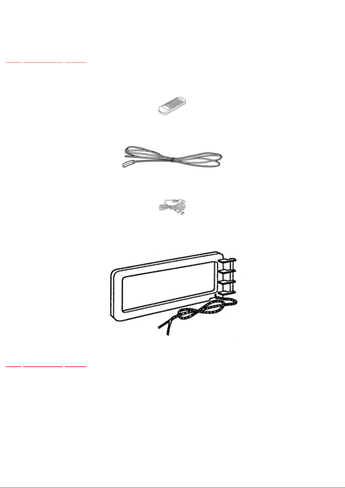
3 Accessories
TOP PREVIOUS NEXT
Remote Control Transmitter
FM indoor antenna
AC mains lead
AM Loop antenna
TOP PREVIOUS NEXT
file:///C|/Documents%20and%20Settings/Moi/Mes%20doc...NASONIC%20SA-AK52EE/SA-AK52EE/SVC/s0300000000x.html03/08/2005 21:38:11
file:///C|/Documents%20and%20Settings/Moi/Mes%20documents/PANASONIC%20SA-AK52EE/SA-AK52EE/SVC/s0400000000x.html
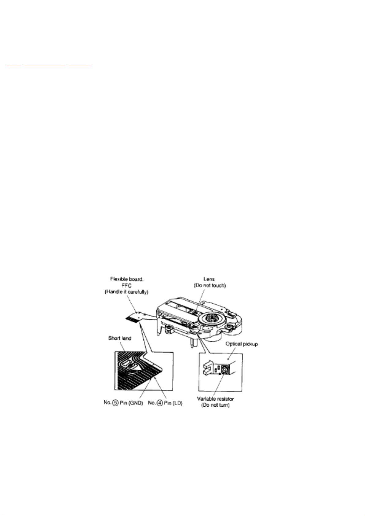
4 Handling Precautions For Traverse Deck
TOP PREVIOUS NEXT
The laser diode in the traverse deck (optical pickup) may break down due to potential difference
caused by static electricity of clothes or human body.
So, be careful of electrostatic breakdown during repair of the traverse deck (optical pickup).
● Handling of traverse deck (optical pickup)
1. Do not subject the traverse deck (optical pickup) to static electricity as it is extremely sensitive
to electrical shock.
2. The short land between the No.4(LD) and No.5(GND) pins on the flexible board (FFC) is
shorted with a solder build-up to prevent damage to the laser diode.To connect to the PC
board, be sure to open by removing the solder build-up, and finishthe work quickly.
3. Take care not to apply excessive stress to the flexible board (FFC).
4. Do not turn the variable resistor (laser power adjustment). It has already been adjusted.
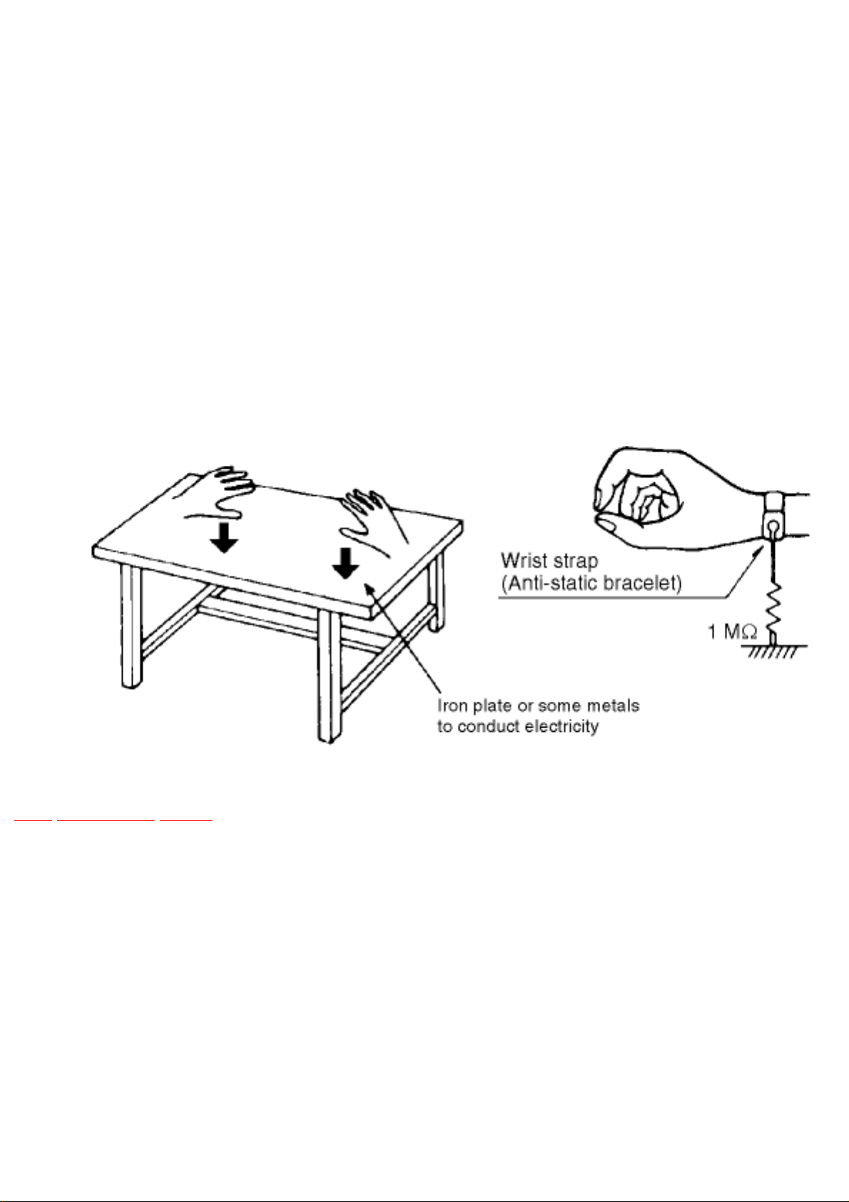
● Grounding for electrostatic breakdown prevention
1. Human body grounding
Use the anti-static wrist strap to discharge the static electricity from your body.
file:///C|/Documents%20and%20Settings/Moi/Mes%20...ONIC%20SA-AK52EE/SA-AK52EE/SVC/s0400000000x.html (1 of 2)03/08/2005 21:38:11
file:///C|/Documents%20and%20Settings/Moi/Mes%20documents/PANASONIC%20SA-AK52EE/SA-AK52EE/SVC/s0400000000x.html
2. Work table grounding
Put a conductive material (sheet) or steel sheet on the area where the traverse deck
(optical pickup) is placed, and ground the sheet.
Caution :
The static electricity of your clothes will not be grounded through the wrist strap. So, take care
not to let your clothes touch the traverse deck (optical pickup).
Caution when Replacing the Traverse Deck :
The traverse deck has a short point shorted with solder to protect the laer diode against
electroststics breakdown. Be sure to remove the solder from the short point before making
connections.
TOP PREVIOUS NEXT
file:///C|/Documents%20and%20Settings/Moi/Mes%20...ONIC%20SA-AK52EE/SA-AK52EE/SVC/s0400000000x.html (2 of 2)03/08/2005 21:38:11

file:///C|/Documents%20and%20Settings/Moi/Mes%20documents/PANASONIC%20SA-AK52EE/SA-AK52EE/SVC/s0500000000x.html
5 Precaution of Laser Diode
TOP PREVIOUS NEXT
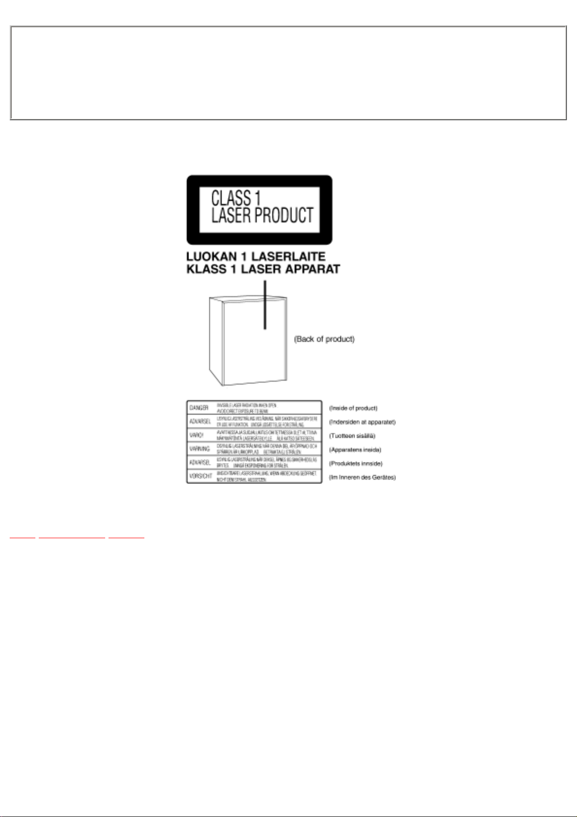
Caution :
This product utilizes a laser diode with the unit turned "ON", invisible laser radiation is emitted from
the pick up lens./Wavelength : 780 nm/Maximum output radiation power from pick up : 100 μW/
VDE/Laser radiation frompick up unit is safety level, but be sure the followings:
1. Do not disassemble the optical pick up unit, since radiation from exposed laser diode is
dangerous.
2. Do not adjust the variable resistor on the pick up unit. It was already adjusted.
3. Do not look at the focus lens using optical instruments.
4. Recommend not to look at pick up lens for a long time.
ACHTUNG :
Dieses Produkt enthält eine Laserdiode. Im eingeschalteten Zustand wird unsichtbare Laserstrahlung
von der Lasereinheit abgestrahlt./Wellenlänge : 780nm/Maximale Strahlungsleistung der
Lasereinheit :100 μW/VDE/DieStrahlung an der Lasereinheit ist ungefährlich, wenn folgende
Punkte beachtet werden:
1. Die Lasereinheit nicht zerlegen, da die Strahlung an der freigelegten Laserdiode gefährlich ist.
2. Den werkseitig justierten Einstellregler der Lasereinhit nicht verstellen.
3. Nicht mit optischen Instrumenten in die Fokussierlinse blicken.
4. Nicht über längere Zeit in die Fokussierlinse blicken.
ADVARSEL :
I dette a apparat anvendes laser.
file:///C|/Documents%20and%20Settings/Moi/Mes%20...ONIC%20SA-AK52EE/SA-AK52EE/SVC/s0500000000x.html (1 of 2)03/08/2005 21:38:12
file:///C|/Documents%20and%20Settings/Moi/Mes%20documents/PANASONIC%20SA-AK52EE/SA-AK52EE/SVC/s0500000000x.html
CAUTION!
THIS PRODUCT UTILIZES A LASER.
USE OF CONTROLS OR ADJUSTMENTS OR PERFORMANCE OF PROCEDURES OTHER THAN THOSE SPECIFIED
HEREIN MAY RESULT IN HAZARDOUS RADIATION EXPOSURE.
Use of Caution Labels
TOP PREVIOUS NEXT
file:///C|/Documents%20and%20Settings/Moi/Mes%20...ONIC%20SA-AK52EE/SA-AK52EE/SVC/s0500000000x.html (2 of 2)03/08/2005 21:38:12
file:///C|/Documents%20and%20Settings/Moi/Mes%20documents/PANASONIC%20SA-AK52EE/SA-AK52EE/SVC/s0600000000x.html
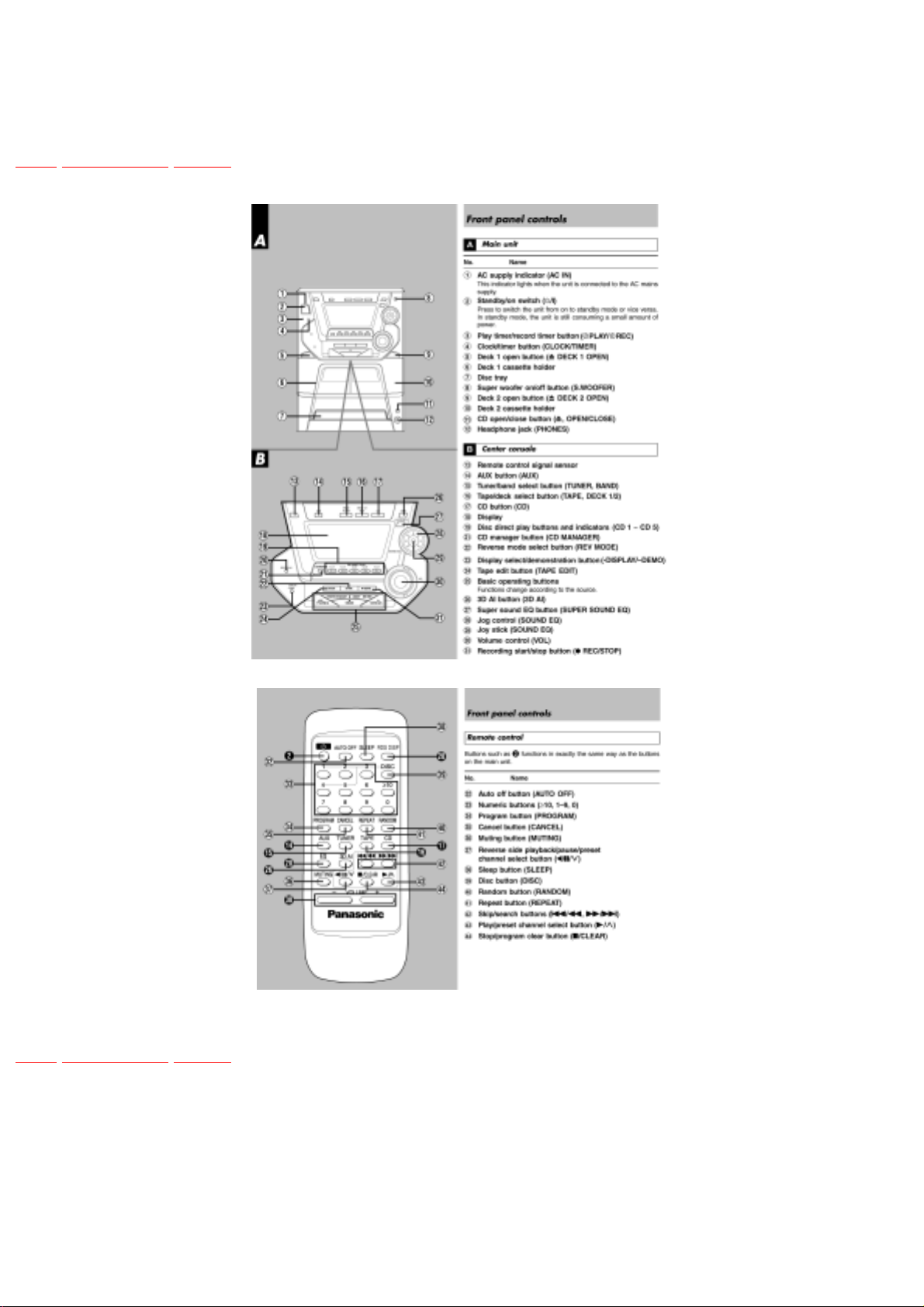
6 Operation Procedures
TOP PREVIOUS NEXT
TOP PREVIOUS NEXT
file:///C|/Documents%20and%20Settings/Moi/Mes%20doc...NASONIC%20SA-AK52EE/SA-AK52EE/SVC/s0600000000x.html03/08/2005 21:38:12
file:///C|/Documents%20and%20Settings/Moi/Mes%20documents/PANASONIC%20SA-AK52EE/SA-AK52EE/SVC/s0700000000e.html
7 Disassembly and Main Component Replacement
Procedures
TOP PREVIOUS NEXT
“ATTENTION SERVICER”
Some chassis components may have sharp edges.
Be careful when disassembling and servicing.
1. This section describes procedures for checking the operation of the major printed circuit boards and
replacing the main components.
2. For reassembly after operation checks or replacement, reverse the respective procedures.
Special reassembly procedures are described only when required.
3. Select items from the following index when checks or replacement are required.
Contents
● Disassembly and assembly main unit
1. Checking of the Main, Panel, Deck and Power P.C.B.
2. Checking of the Power P.C.B.
file:///C|/Documents%20and%20Settings/Moi/Mes%20...ONIC%20SA-AK52EE/SA-AK52EE/SVC/s0700000000e.html (1 of 2)03/08/2005 21:38:13

file:///C|/Documents%20and%20Settings/Moi/Mes%20documents/PANASONIC%20SA-AK52EE/SA-AK52EE/SVC/s0700000000e.html
● Main Component Replacement Procedures
1. Replacement of the Traverse Deck.
2. Replacement of the Power Amplifier IC.
● Disassembly and assembly of the Traverse Unit
● Disassembly and assembly of the Disc Tray
Warning:
This product uses a laser diode. Refer to caution statement Precaution of Laser Diode.
ACHTUNG :-
● Die Lasereinheit nicht zerlegen.
● Die Lasereinheit darf nur gegen eine vom Hertsteller spezifizierte Einheit ausgetauscht werden.
7.1 Disassembly Procedure For Each Major P.C.B. Checking
7.1.1 Checking of the Main, Transformer, Panel and Deck P.C.B.
7.1.2 Checking of the Power P.C.B.
7.2 Main Component Replacement Procedures
7.3 Disassembly and assembly of the Traverse Unit
7.4 Disassembly and assembly of the Disc Tray
TOP PREVIOUS NEXT
file:///C|/Documents%20and%20Settings/Moi/Mes%20...ONIC%20SA-AK52EE/SA-AK52EE/SVC/s0700000000e.html (2 of 2)03/08/2005 21:38:13

file:///C|/Documents%20and%20Settings/Moi/Mes%20documents/PANASONIC%20SA-AK52EE/SA-AK52EE/SVC/s0701000000.html
7.1 Disassembly Procedure For Each Major P.C.
B. Checking
TOP PREVIOUS NEXT
7.1.1 Checking of the Main, Transformer, Panel and Deck P.C.B.
7.1.2 Checking of the Power P.C.B.
TOP PREVIOUS NEXT
file:///C|/Documents%20and%20Settings/Moi/Mes%20do...NASONIC%20SA-AK52EE/SA-AK52EE/SVC/s0701000000.html03/08/2005 21:38:13
file:///C|/Documents%20and%20Settings/Moi/Mes%20documents/PANASONIC%20SA-AK52EE/SA-AK52EE/SVC/s0701010000.html
7.1.1 Checking of the Main, Transformer, Panel
and Deck P.C.B.
TOP PREVIOUS NEXT
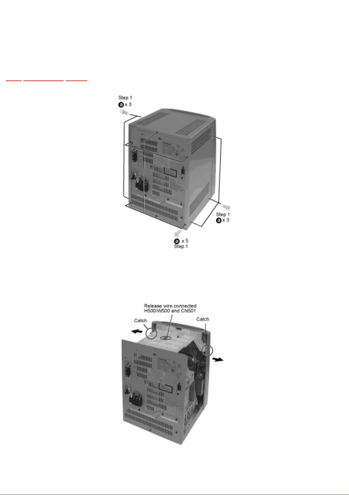
Step 2 Remove the top cabinet.
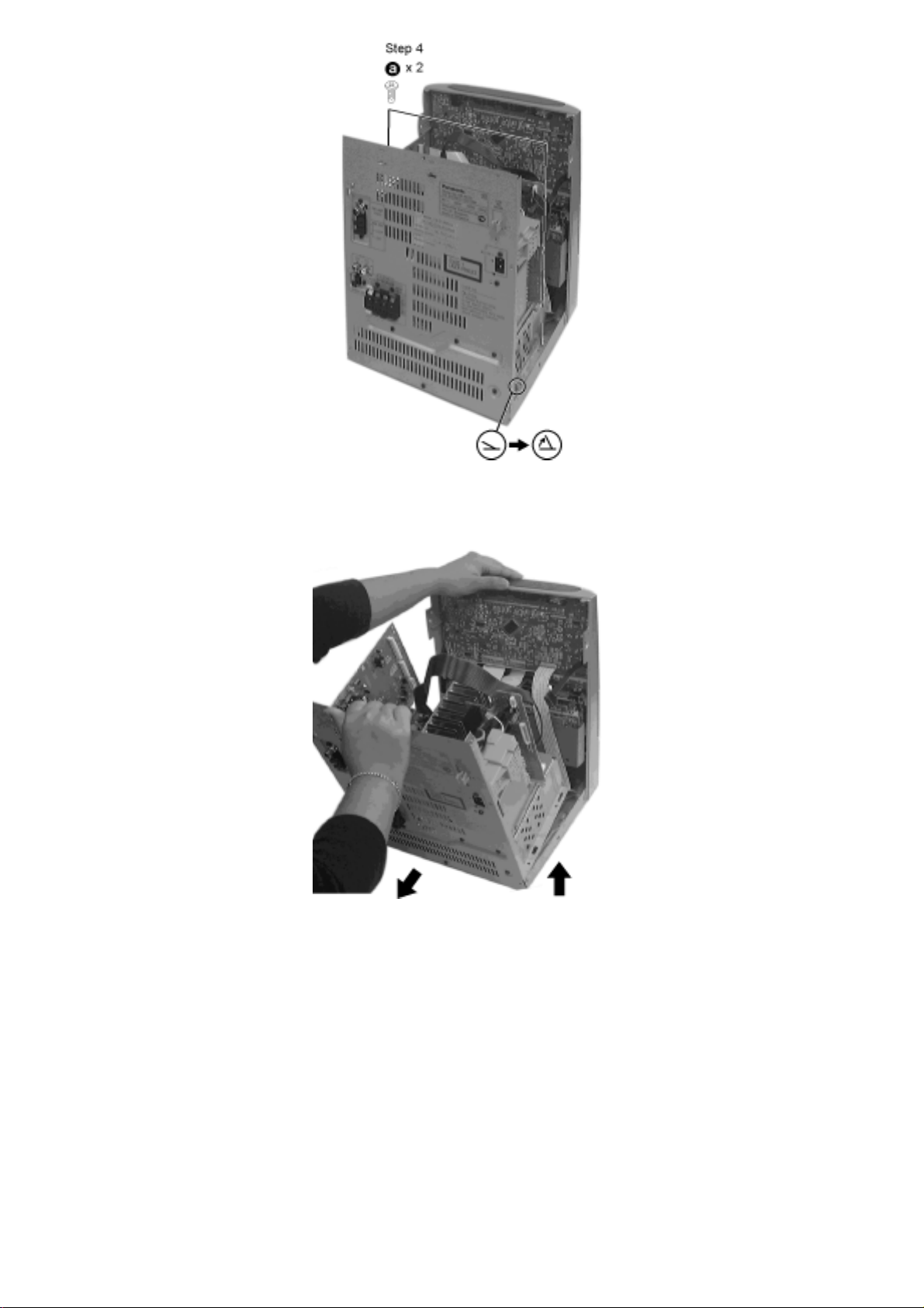
Step 3 Remove the T-bracket.
file:///C|/Documents%20and%20Settings/Moi/Mes%20...SONIC%20SA-AK52EE/SA-AK52EE/SVC/s0701010000.html (1 of 5)03/08/2005 21:38:14
file:///C|/Documents%20and%20Settings/Moi/Mes%20documents/PANASONIC%20SA-AK52EE/SA-AK52EE/SVC/s0701010000.html
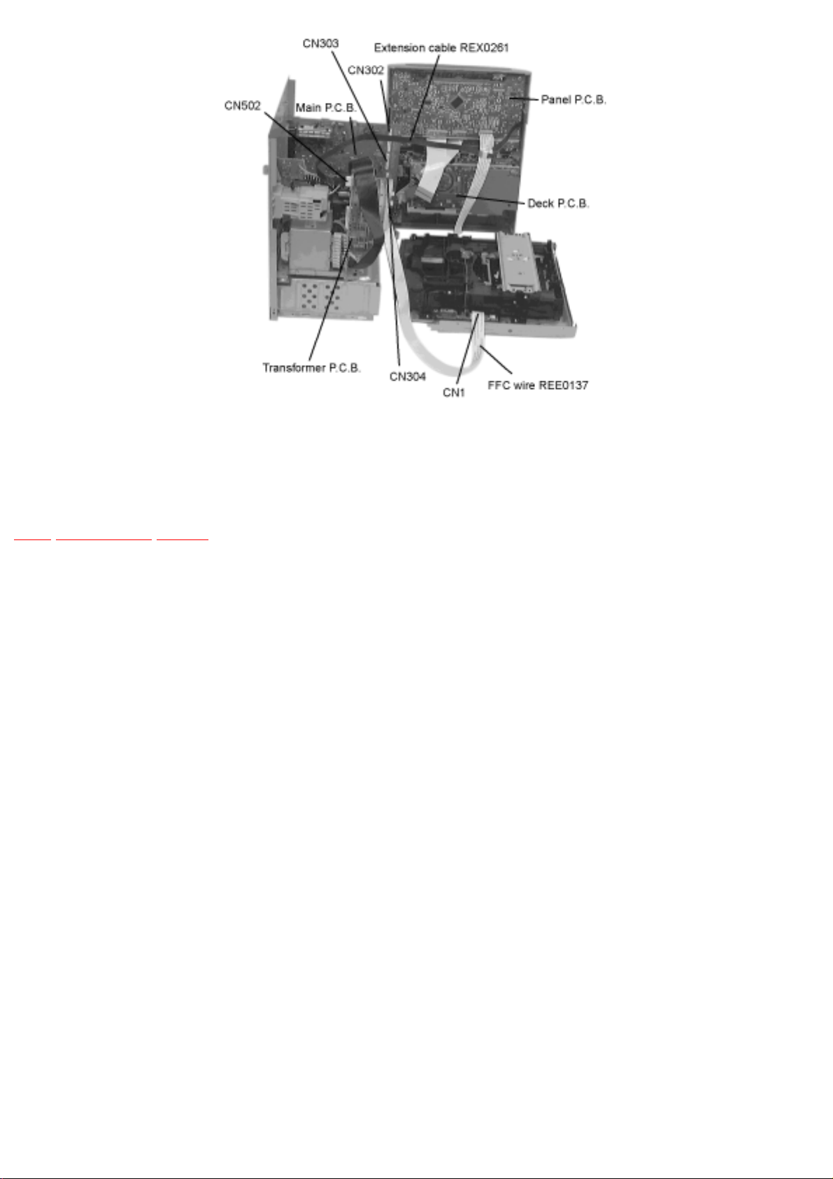
Step 5 Turn locating pin on both sides 90°. (Locating pin need not to be bent back.)
Step 6 Release the wires CN302, CN303, CN304, CN309 and CN502. Remove rear panel by pulling
it backward and lift the rear panel assembly.
file:///C|/Documents%20and%20Settings/Moi/Mes%20...SONIC%20SA-AK52EE/SA-AK52EE/SVC/s0701010000.html (2 of 5)03/08/2005 21:38:14
file:///C|/Documents%20and%20Settings/Moi/Mes%20documents/PANASONIC%20SA-AK52EE/SA-AK52EE/SVC/s0701010000.html
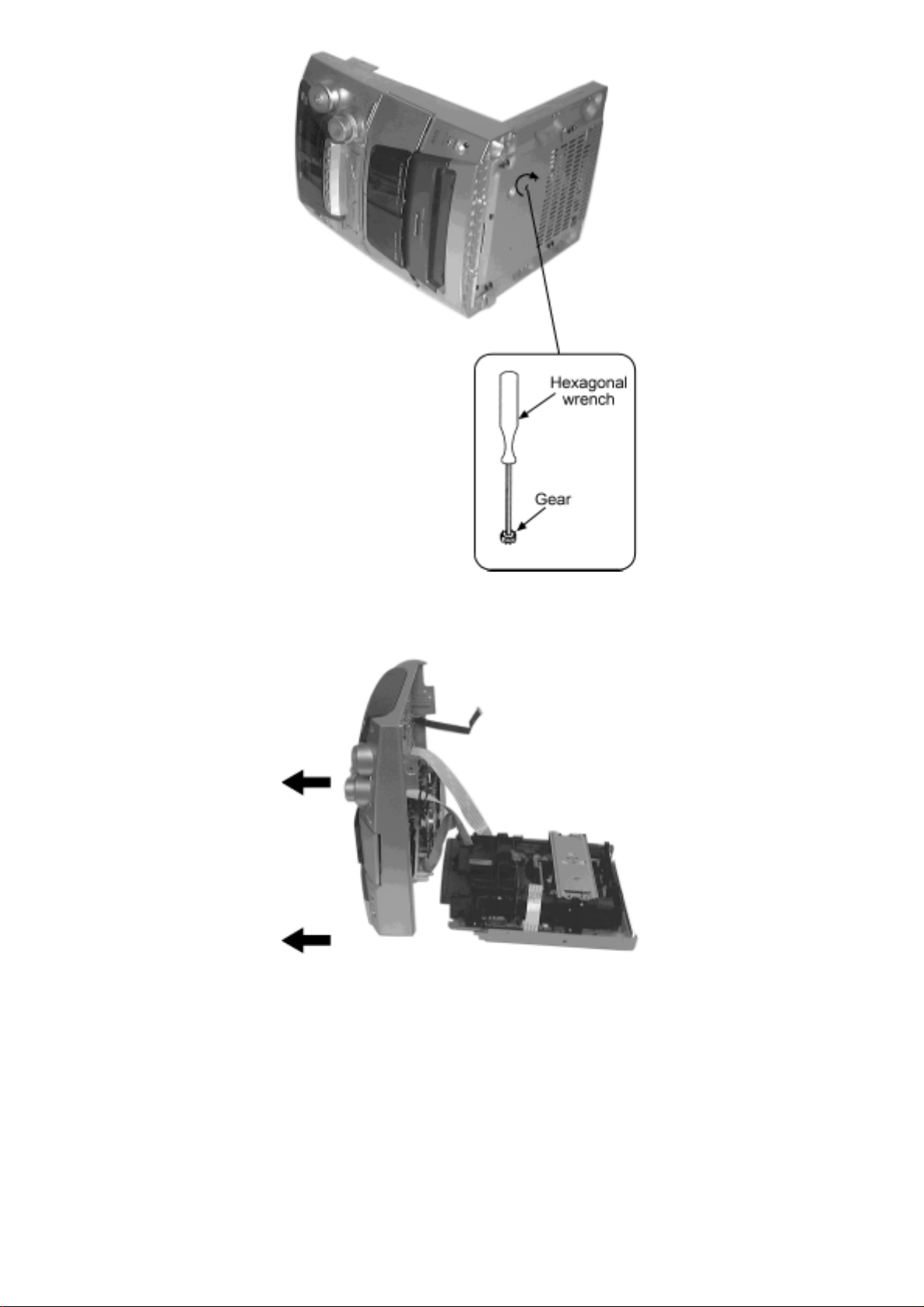
Step 7 Use a hexagonal wrench and turn clockwise to release the tray.
Step 8 Pull the CD tray in the direction shown above.
file:///C|/Documents%20and%20Settings/Moi/Mes%20...SONIC%20SA-AK52EE/SA-AK52EE/SVC/s0701010000.html (3 of 5)03/08/2005 21:38:14
file:///C|/Documents%20and%20Settings/Moi/Mes%20documents/PANASONIC%20SA-AK52EE/SA-AK52EE/SVC/s0701010000.html
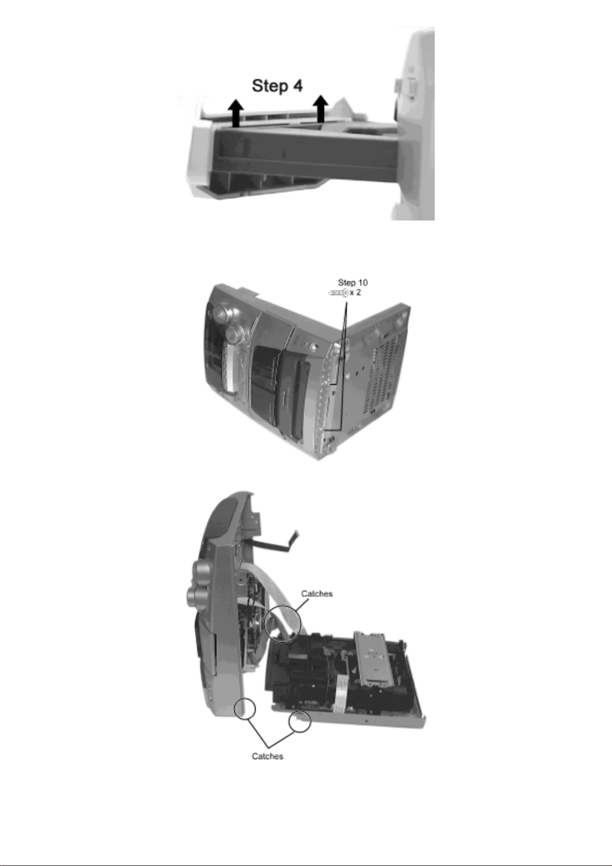
Step 9 Remove the CD lid in the direction of the arrow.
Step 11 Release the two catches shown above to remove the front cabinet from the CD traverse unit.
file:///C|/Documents%20and%20Settings/Moi/Mes%20...SONIC%20SA-AK52EE/SA-AK52EE/SVC/s0701010000.html (4 of 5)03/08/2005 21:38:14
file:///C|/Documents%20and%20Settings/Moi/Mes%20documents/PANASONIC%20SA-AK52EE/SA-AK52EE/SVC/s0701010000.html
Step 12 Connect back the wire to CN302, CN303 and CN304. Use the extension wire (REXX0261)
to connect to CN502. Use a FFC wire (REEX0137) to connect CN1 to CN309.
TOP PREVIOUS NEXT
file:///C|/Documents%20and%20Settings/Moi/Mes%20...SONIC%20SA-AK52EE/SA-AK52EE/SVC/s0701010000.html (5 of 5)03/08/2005 21:38:14
file:///C|/Documents%20and%20Settings/Moi/Mes%20documents/PANASONIC%20SA-AK52EE/SA-AK52EE/SVC/s0701020000.html
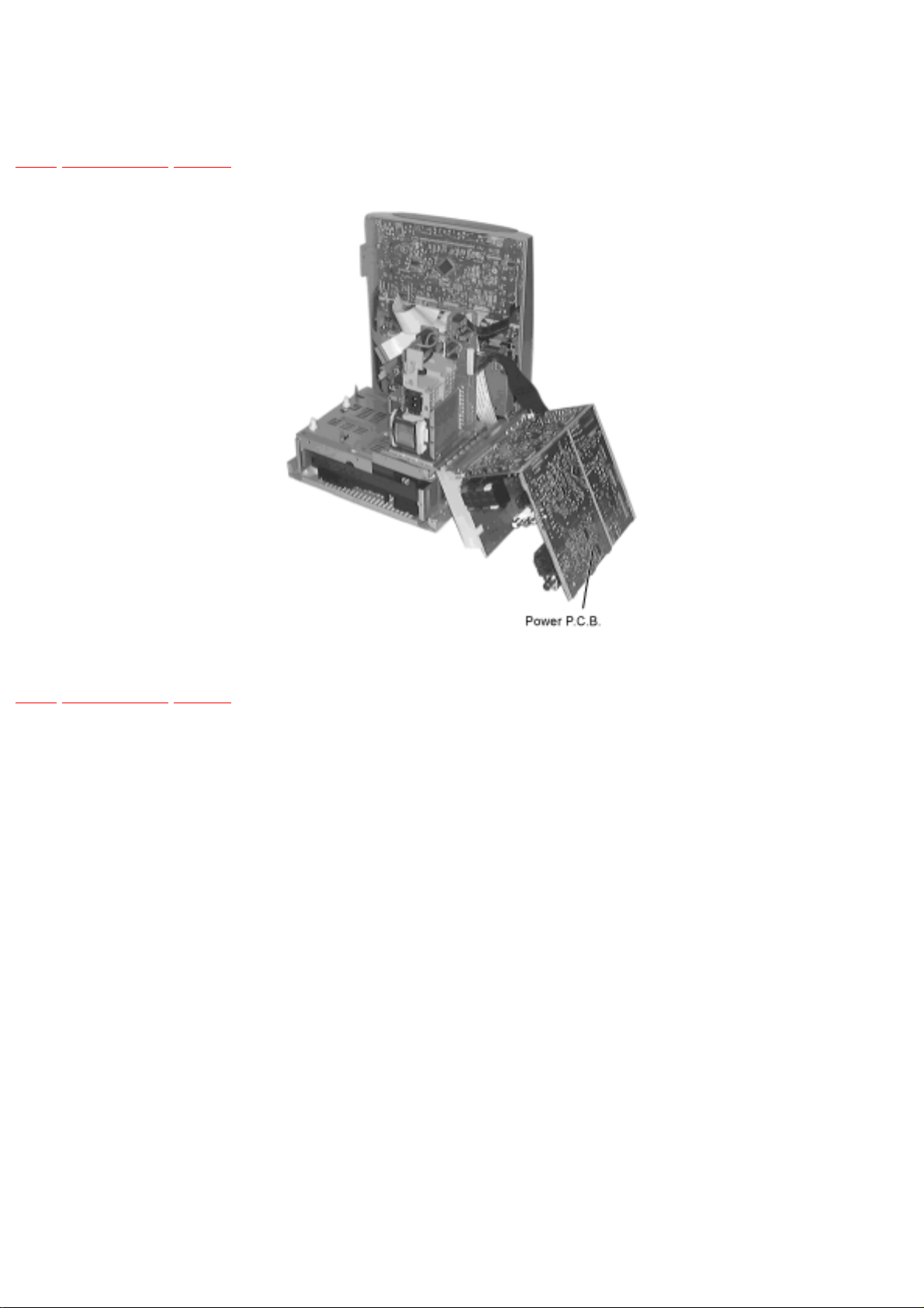
7.1.2 Checking of the Power P.C.B.
TOP PREVIOUS NEXT
TOP PREVIOUS NEXT
file:///C|/Documents%20and%20Settings/Moi/Mes%20do...NASONIC%20SA-AK52EE/SA-AK52EE/SVC/s0701020000.html03/08/2005 21:38:15
file:///C|/Documents%20and%20Settings/Moi/Mes%20documents/PANASONIC%20SA-AK52EE/SA-AK52EE/SVC/s0702000000.html
7.2 Main Component Replacement Procedures
TOP PREVIOUS NEXT
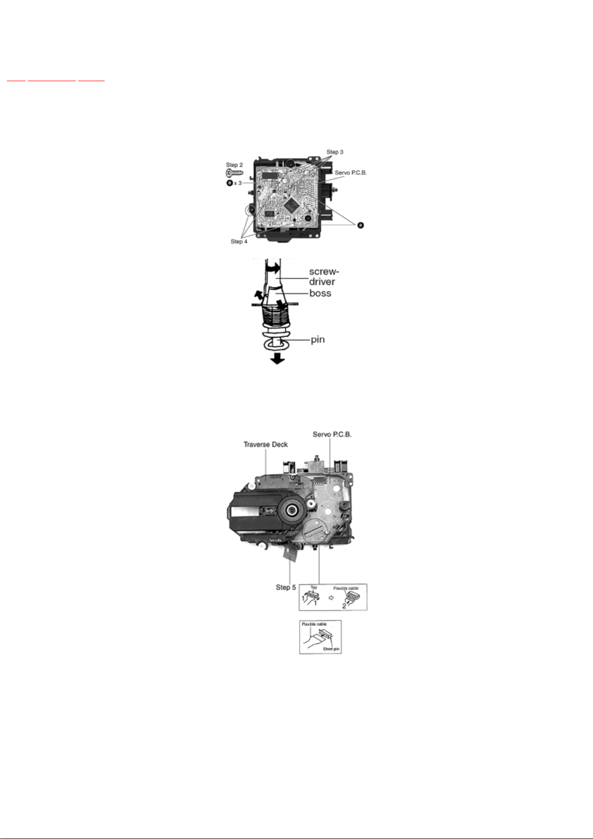
1. Replacement of the Traverse Deck
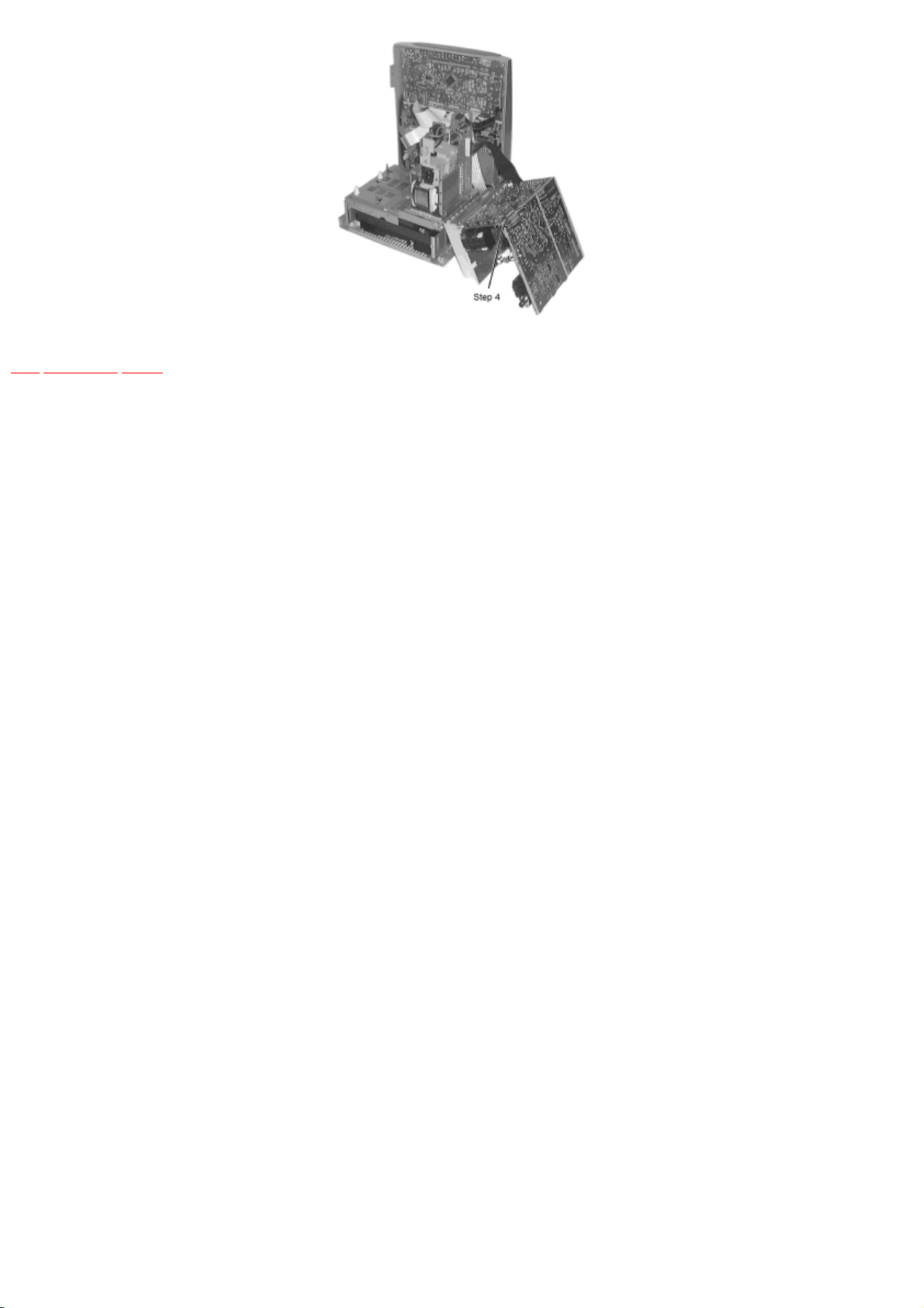
Step 1 Follow the procedures in ‘Disassembly of the Traverse Unit’ ( Step 1 - Step 4 )
Step 3 Desolder the 4 legs of the 2 motors and pull out the Servo P.C.B.
Step 4 Widen the 3 bosses with a flat screwdriver and pull out the 3 pins. Then remove the Traverse Deck.
Step 5 Remove the flexible cable CN 701.
● Removal of the flexible cable. Push the top of the connector in the direction of the arrow 1, and then pull out the flexible cable in the
direction of the arrow 2.
Note:
Insert a short pin into the flexible cable for traverse unit.
● Installation of the CD servo P.C.B. after replacement
file:///C|/Documents%20and%20Settings/Moi/Mes%20...SONIC%20SA-AK52EE/SA-AK52EE/SVC/s0702000000.html (1 of 4)03/08/2005 21:38:15
file:///C|/Documents%20and%20Settings/Moi/Mes%20documents/PANASONIC%20SA-AK52EE/SA-AK52EE/SVC/s0702000000.html
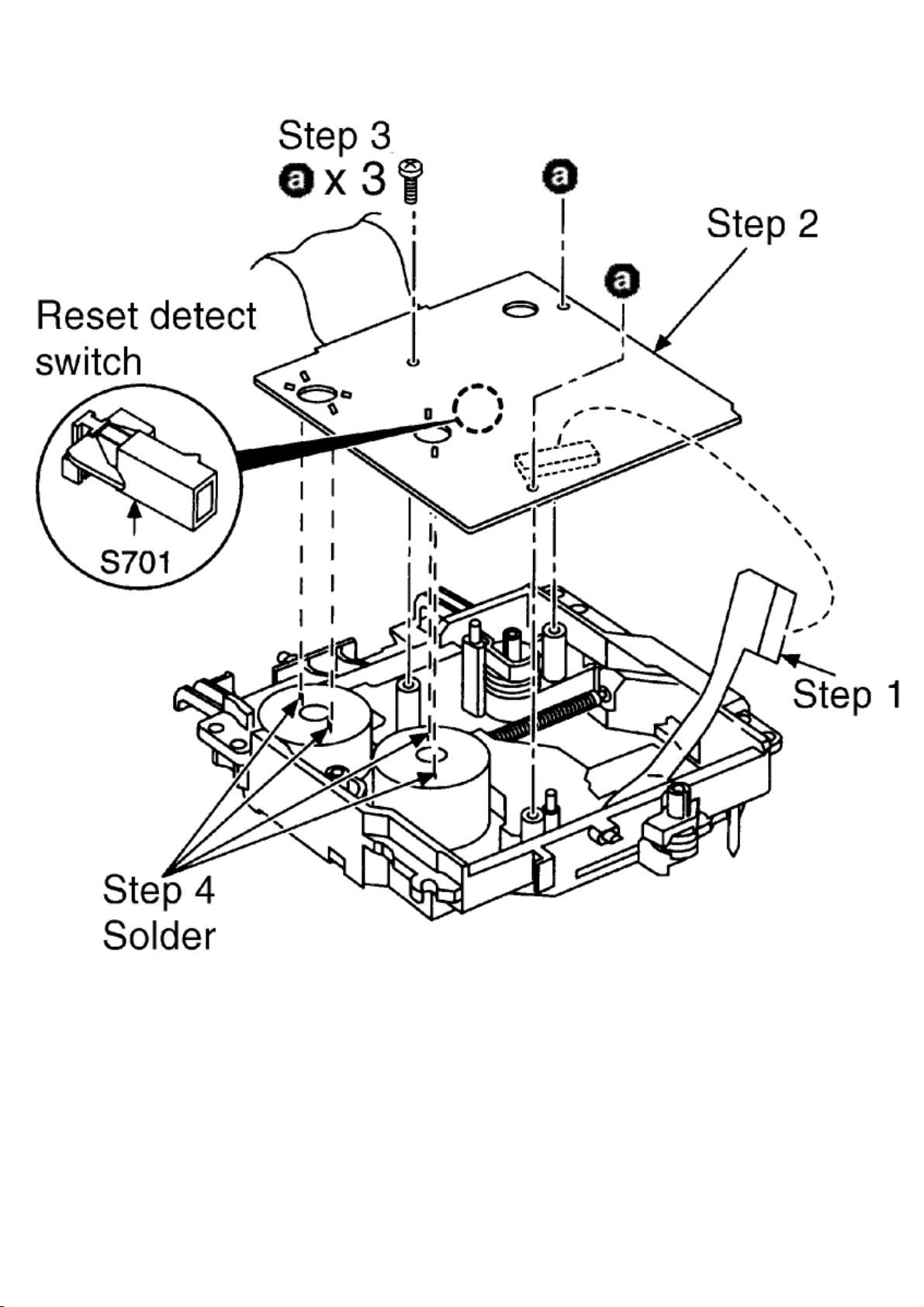
Step 1 Connect the FFC board.
Step 2 Install the CD servo P.C.B. in the traverse deck assembly.
Note:
Before installing the CD servo P.C.B., move the optical pickup towards the outer edge from the marking (black triangle). [Otherwise, the reset
detect switch (S701) mounted on the CD servo P.C.B. may be damaged.]
file:///C|/Documents%20and%20Settings/Moi/Mes%20...SONIC%20SA-AK52EE/SA-AK52EE/SVC/s0702000000.html (2 of 4)03/08/2005 21:38:15

file:///C|/Documents%20and%20Settings/Moi/Mes%20documents/PANASONIC%20SA-AK52EE/SA-AK52EE/SVC/s0702000000.html
2. Replacement of the Power Amplifier IC
Step 1 Follow the procedures in ‘Checking Procedure for each major P.C.B.’ ( Step 1 - Step 4 ).
Step 2 Remove the wires at CN302, CN303 and CN304 and pull out the Main P.C.B.
Step 3 Remove 4 screws fixed to the Power Amplifier IC.
Step 4 Unsolder the terminals of Power Amp IC and replace the respective component.
file:///C|/Documents%20and%20Settings/Moi/Mes%20...SONIC%20SA-AK52EE/SA-AK52EE/SVC/s0702000000.html (3 of 4)03/08/2005 21:38:15
file:///C|/Documents%20and%20Settings/Moi/Mes%20documents/PANASONIC%20SA-AK52EE/SA-AK52EE/SVC/s0702000000.html
TOP PREVIOUS NEXT
file:///C|/Documents%20and%20Settings/Moi/Mes%20...SONIC%20SA-AK52EE/SA-AK52EE/SVC/s0702000000.html (4 of 4)03/08/2005 21:38:15
file:///C|/Documents%20and%20Settings/Moi/Mes%20documents/PANASONIC%20SA-AK52EE/SA-AK52EE/SVC/s0703000000.html
7.3 Disassembly and assembly of the Traverse
Unit
TOP PREVIOUS NEXT
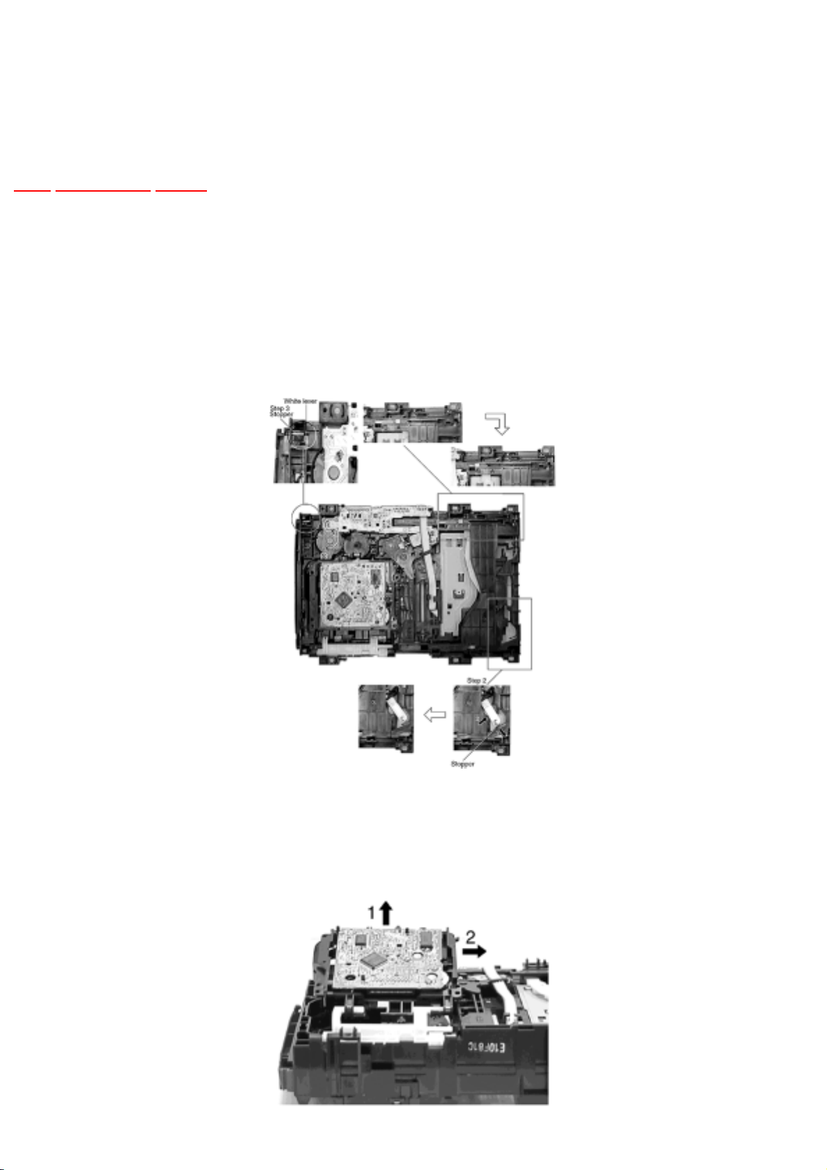
Step 1 Push the lever from position A to B.
Step 2 Pull the stopper (black) in the direction of arrow 1 and push the lever in the direction of arrow
2.
Step 3 Push the stpeer (black) down until the white lever eject out.
Step 4 Lift up the traverse unit and slide out the unit as shown.
● Replacement of Traverse Unit
file:///C|/Documents%20and%20Settings/Moi/Mes%20...SONIC%20SA-AK52EE/SA-AK52EE/SVC/s0703000000.html (1 of 3)03/08/2005 21:38:16
file:///C|/Documents%20and%20Settings/Moi/Mes%20documents/PANASONIC%20SA-AK52EE/SA-AK52EE/SVC/s0703000000.html
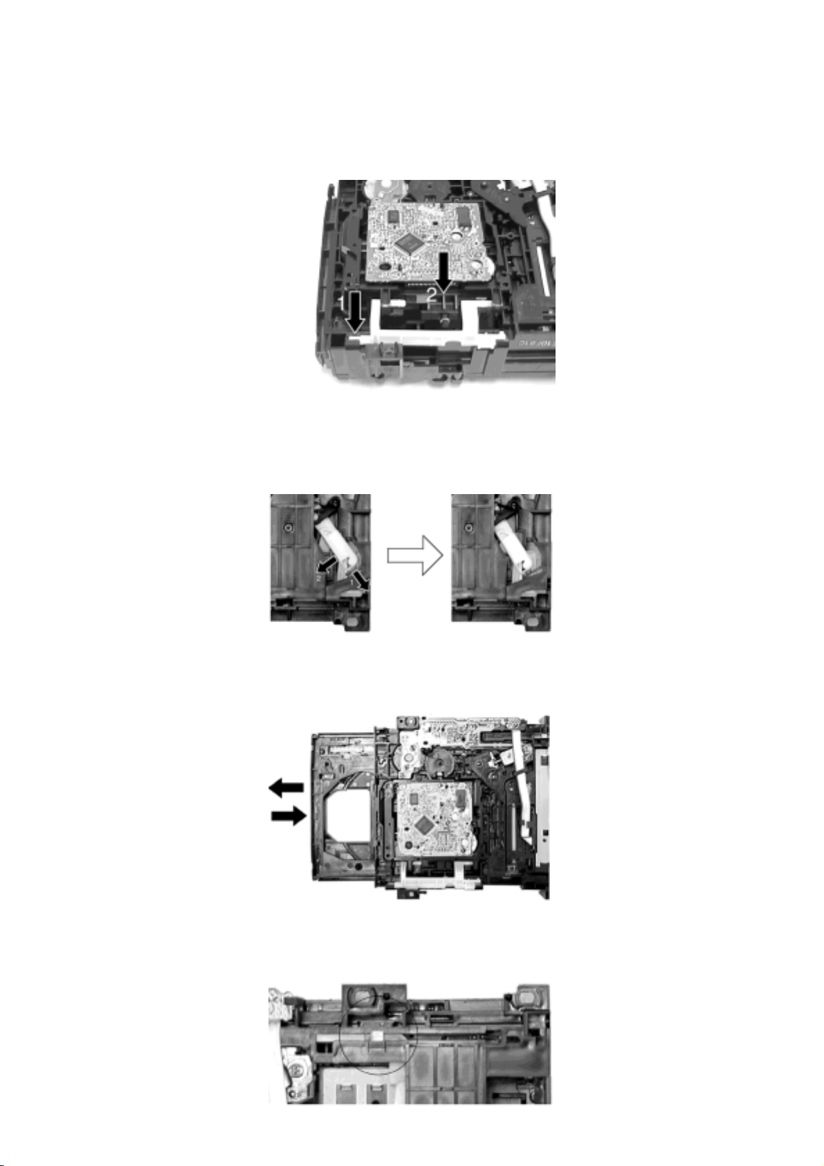
Step 1 Place the traverse unit as shown.
Step 2 Press in the lever shaft in the direction of arrow 1 as shown and push the traverse unit into the
position in the direction of arrow 2.
Step 3 Pull the stopper in the direction of arrow 1 and release the lever in the direction of arrow 2 as
shown.
Step 4 Pull out the tray half way and push it back fully.
Step 5 Push the lever to the initial position indicated ‘I---I’.
file:///C|/Documents%20and%20Settings/Moi/Mes%20...SONIC%20SA-AK52EE/SA-AK52EE/SVC/s0703000000.html (2 of 3)03/08/2005 21:38:16
 Loading...