


Panasonic SAAK-44 Service manual
Cassette Mechanism
Semi-auto Cassette
Mechanism Operation Description
AR-2
T e chnical Support Section, Quality Promotion Department, Audio Division

Contents
page
Mechanism bottom view and part names...................................................1
Mechanism top view and part names.........................................................2
Drive system...............................................................................................3
Operation of the main gear from the stop mode to the play mode .............4
Switching between forward and reverse during the play mode ..................5
Operation of the forward/reverse lever and forward/reverse rod.................6
Operation of the main gear and forward/reverse lever................................6
Head switching operation/Pinch roller switching operation.........................7
Operational relationship between head substrate and main gear ..............8
Reel base mode switching operation
(stop, forward-play, and reverse-play modes).....................................9
Relationship between take-up arm, main gear,
and reel base gears (during play mode) ..........................................10
Reel base switching mode (fast-forward, rewind, and stop modes) .........11
Eject operation (stop mode) .....................................................................12
Eject operation (cassette cover open)......................................................13
Block diagram...........................................................................................14
Timing chart .............................................................................................15
Fast Forward (FF) and Rewind (REW) .....................................................16
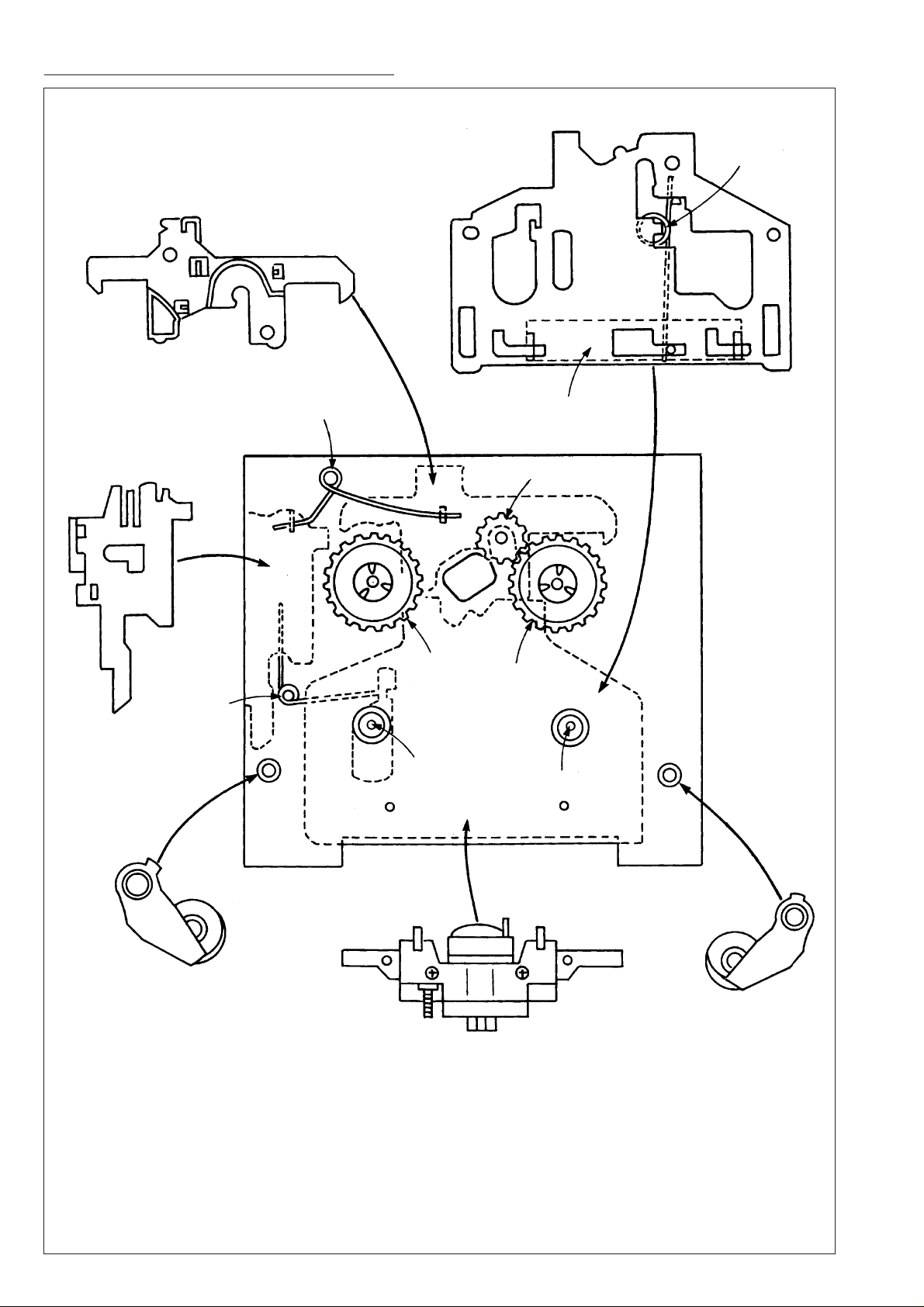
Assembly of parts at top of mechanism ...........................................17 ~ 19
Assembly of parts at bottom of mechanism .....................................20 ~ 23
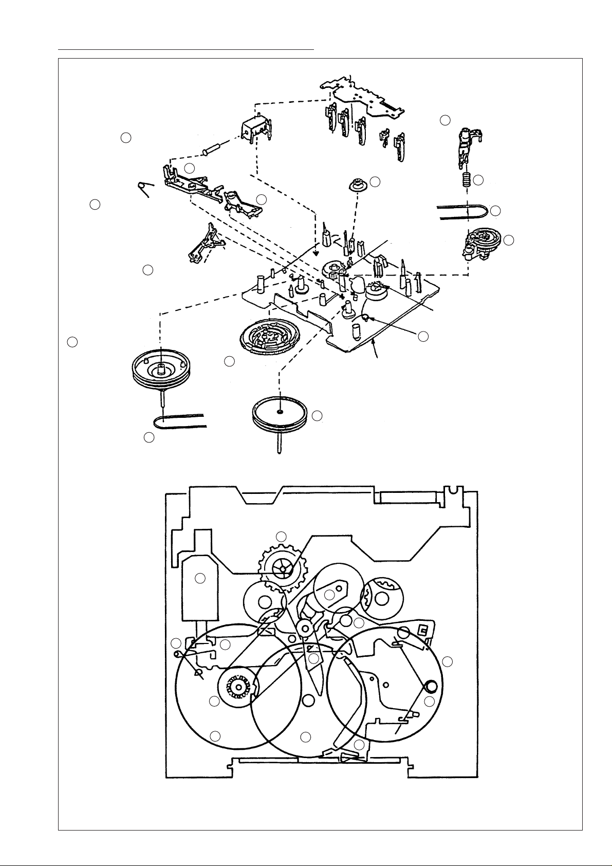
Mechanism bottom view and part names
7
Plunger (solenoid)
3
Trigger lever
4
Trigger lever spring
11
Forward flywheel
1
Forward/reverse lever
2
Eject lever
Switch substrate
6
Fast-forward
relay gear
Reel base gear A
Reel base gear B
5
Forward/reverse lever spring
13
Take-up lever
12
Thrust spring
10
Take-up belt
9
Take-up arm
10
Take-up belt
4
8
Main gear
14
Reverse flywheel
6
7
9
3
13
Chassis
2
14
10
11
8
— 1 —
5
1
Mechanism top view and part names
Brake rod
Head substrate
Forward/reverse
rod spring
Eject rod
Head substrate
return spring
Brake rod spring
Reverse-play
reel base gear
Reverse
capstan
Forward/reverse rod
Play relay gear
Forward-play
reel base gear
Forward capstan
Reverse pinch roller
Forward pinch roller
Head
— 2 —
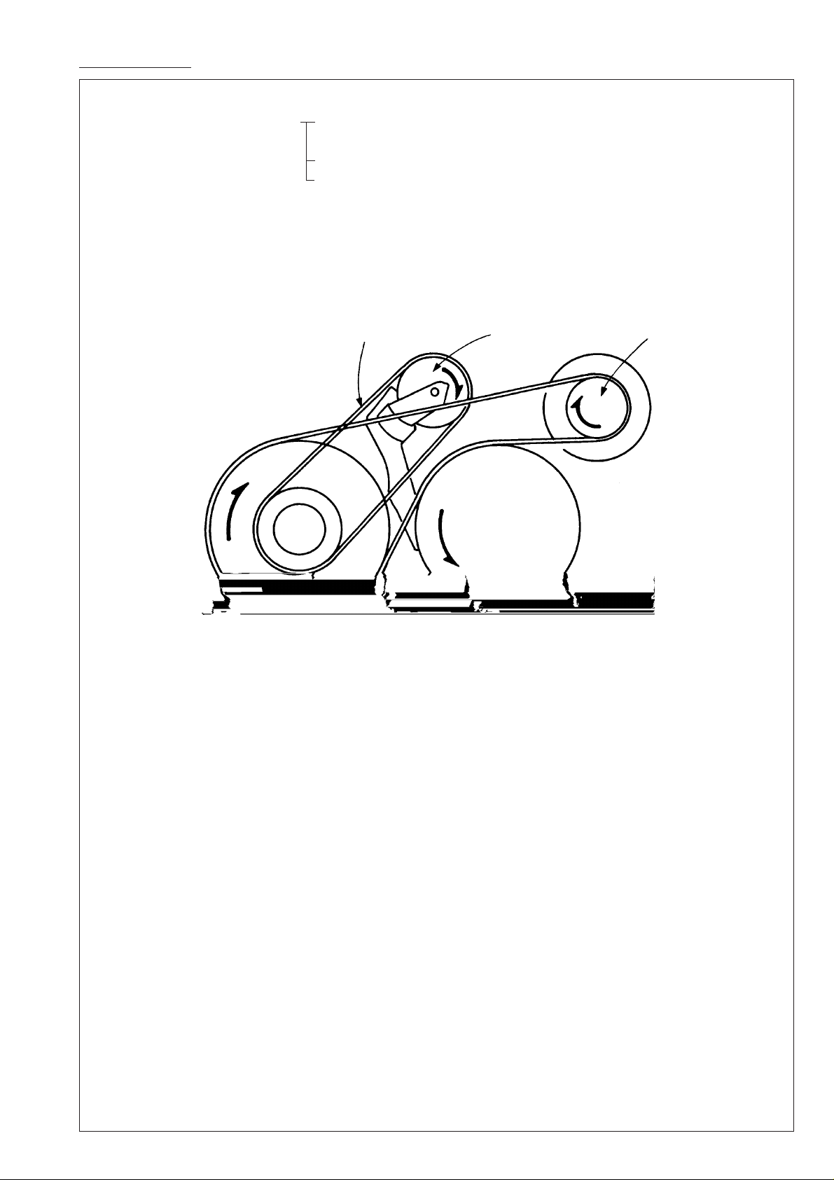
Drive system
1. Transmission of the motor's drive force to the two flywheels via the main belt (capstan drive)
* Driving of the main gear (1) For changing mode to stop, forward-play, reverse-play, fast-for-
ward, and rewind
(2) For changing direction of the head and pinch rollers
(3) For raising and lowering the head substrate
2. Transmission of the forward flywheel's drive force to the take-up arm via the take-up belt
* Driving of the reverse and forward reel bases
3. Motor always rotates in the same direction (direction indicated by the arrow).
Forward flywheel
Take-up belt
Main belt
Take-up arm
Reverse flywheel
Motor pulley
— 3 —
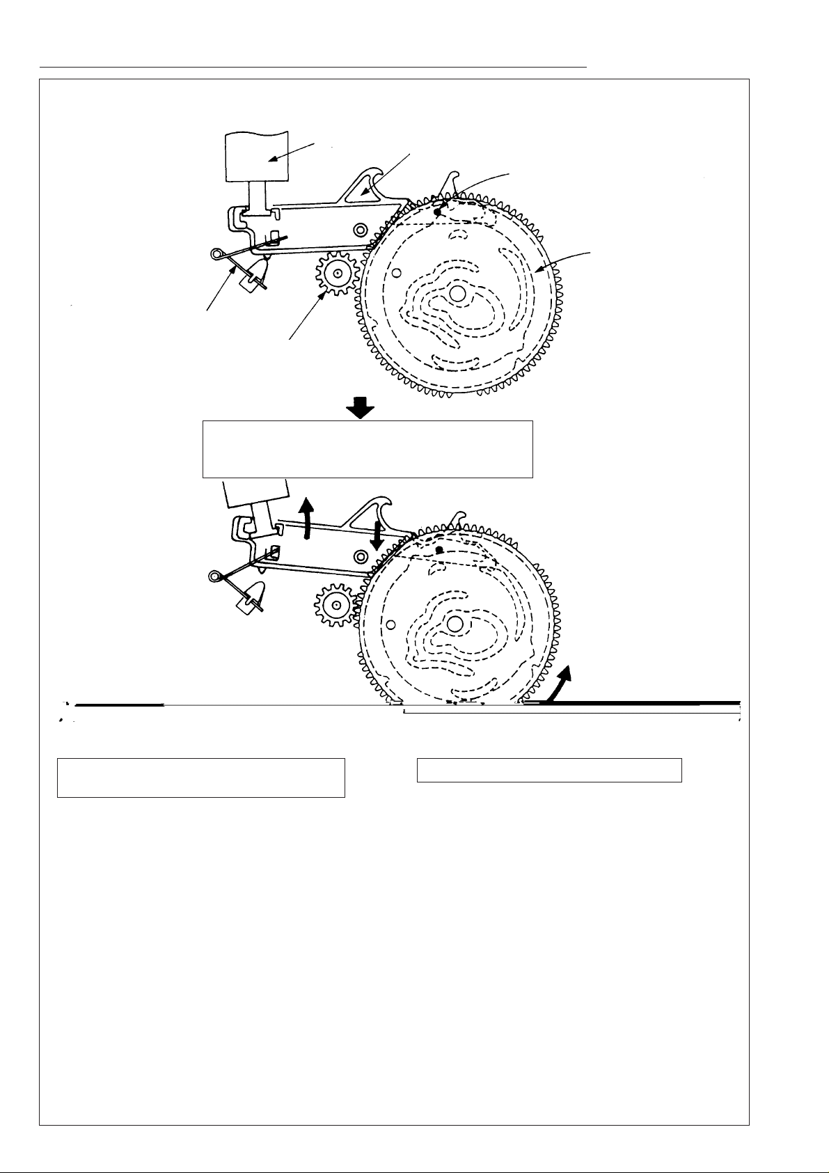
Operation of the main gear from the stop mode to the play mode
<Stop position>
Trigger spring
Forward flywheel gear
When the plunger is drawn in, the main gear
rotates slightly (the flywheelgear and the main
gear engage).
Plunger
Trigger lever
Trigger lever boss
Main gear
Drive force of the forward flywheel gear
causes the main gear to rotate.
Main gear rotates 120˚ and then stops.
<Play position>
R
o
t
a
t
e
s
1
2
0
°
— 4 —
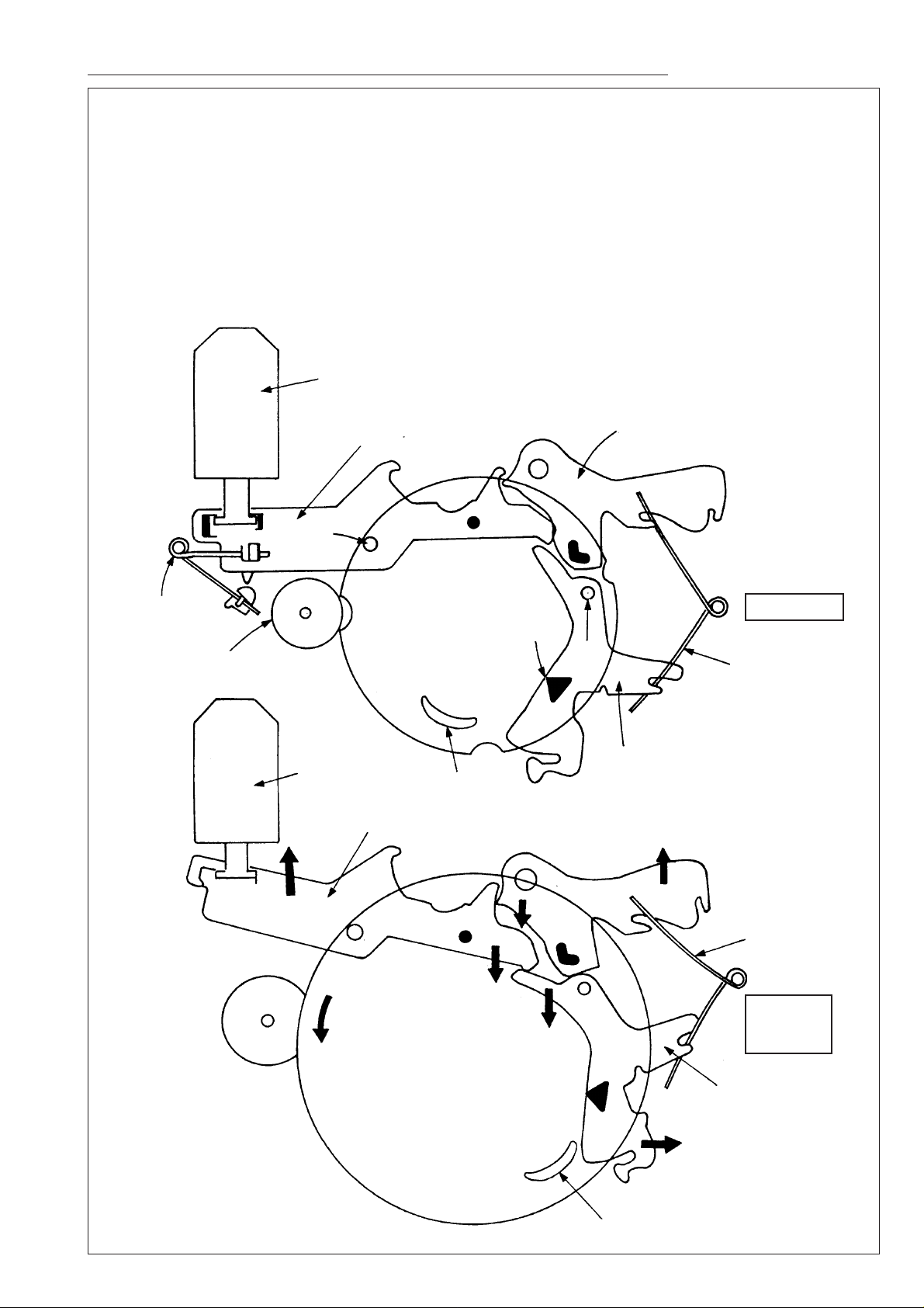
Switching between forward and re v erse during the pla y mode
Plunger
Trigger lever
Fulcrum
Trigger spring
Eject lever
Forward flywheel
Main gear
Protrusion
Fulcrum
Forward/reverse
lever spring
Stop mode
Forward/reverse lever
During
switching
operation
Crescent cam
Plunger
Trigger lever
Forward/reverse
lever spring
Main gear
Crescent cam
Forward/reverse lever
Switching between the forward and rev erse directions is determined by ho w long the plung er is dra wn
in from the stop position.
Drawn in for 50 ms: Forward
Drawn in for 100 ms: Reverse
When the plunger is drawn in, the trigger lever and forward/reverse lever move in the direction indicated by the arrows. And the main gear rotates; the crescent cam on the main gear pushes against the
protrusion on the forward/reverse lever; and switching between the forward and reverse directions is
determined by the direction in which the protrusion is pushed.
In synchronization with this operation, the forward/reverse lever also switches the direction of the
pinch rollers.
— 5 —
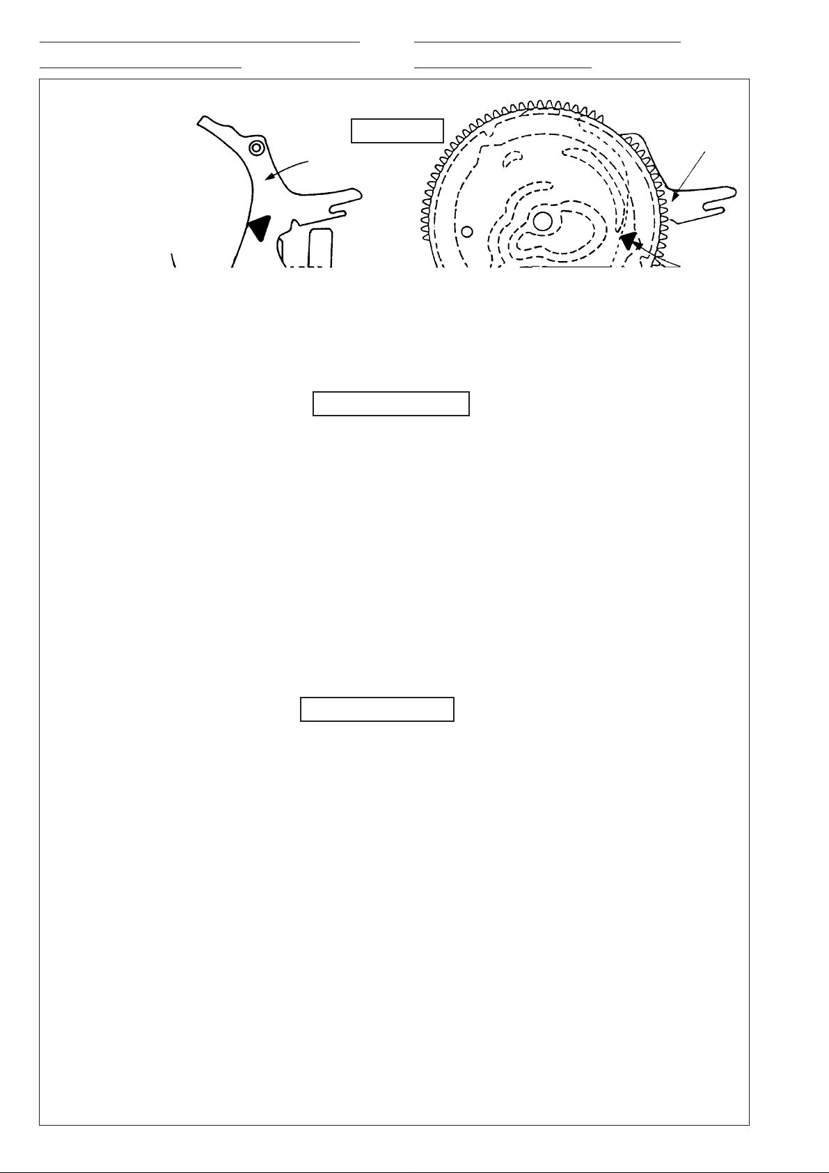
Operation of the f orw ard/reverse lever
Operation of the main gear and
and forward/re v erse rod
Main gear
crescent cam
Forward/reverse
rod
Protrusion
forward/re v erse le v er
Stop mode
Trigger lever
Forward/reverse
rod protrusion
Forward-play mode
Trigger lever
Main gear crescent cam
Forward/
reverse
lever
Forward/
reverse
lever
protrusion
Main gear crescent
cam
Forward/reverse rod
Forward/reverse
rod protrusion
Reverse-play mode
Forward/reverse rod
<Head bottom view>
— 6 —
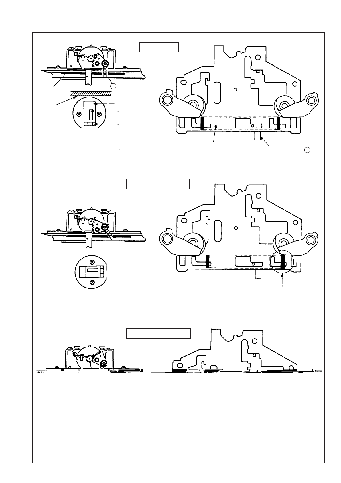
Head switching operation Pinch roller switching operation
Stop mode
Forward-play mode
Reverse-play mode
Chassis
Erase head
Record/playback
head
Tape guide
Head top view
A
Forward/reverse rod
Fits into head spring .
A
When the head substrate is raised,
this part raises the pinch roller.
When the head substrate is raised,
this part raises the pinch roller.
Note: Unlike previously, in the stop mode
the head is in the neutralposition;
this is not a malfunction.
— 7 —