

Panasonic S-22MM1E5A, S-15MM1E5A, S-28MM1E5A, S-45MM1E5S, S-56MM1E5A Installation Instructions Manual

INSTALLATION INSTRUCTIONS
AMP Air Conditioning
www.ampair.co.uk | sales@ampair.co.uk
– VRF System Air Conditioner –
for Refrigerant R410A
R410A Models
■
Model No.
Indoor Units
Type Indoor Unit Type
M1 Slim Low Static Ducted S-15MM1E5A S-22MM1E5A S-28MM1E5A S-36MM1E5A S-45MM1E5A S-56MM1E5A
15
22 28 36 45 56
ENGLISH
Read through the Installation Instructions before you proceed with the installation.
In particular, you will need to read under the “IMPORTANT!” section at the top of the page.
FRANÇAIS
Lisez les instructions d’installation avant de commencer l’installation.
En particulier, vous devez lire la section “IMPORTANT!” en haut de la plage.
ESPAÑOL
Lea las Instrucciones de instalación antes de proceder con la instalación del equipo.
En concreto, deberá leer detenidamente la sección “¡IMPORTANTE!” situada al principio de la página.
DEUTSCH
Lesen Sie die Einbauanleitung, bevor Sie mit der Installation beginnen.
Insbesondere die Hinweise im Abschnitt “WICHTIG!” oben auf der Seite müssen unbedingt gelesen werden.
ITALIANO
Leggere le Istruzioni di installazione prima di procedere con l’installazione.
Prestare particolare attenzione alla sezione “IMPORTANTE!” all’inizio della pagina.
NEDERLANDS
Lees de installatie-instructies zorgvuldig door voor u begint met de installatie.
U moet vooral het gedeelte waar “BELANGRIJK!” boven staat heel goed lezen.
PORTUGUÊS
Leia cuidadosamente as instruções de instalação antes de prosseguir com a instalação.
Em particular, é necessário ler as informações na secção “IMPORTANTE!” na parte superior da página.
ΕΛΛΗΝΙΚΆ
Διαβάστε τις Οδηγίες εγκατάστασης πριν συνεχίσετε με την εγκατάσταση.
Συγκεκριμένα, θα χρειαστεί να διαβάσετε την ενότητα «ΣΗΜΑΝΤΙΚΟ!» στο πάνω μέρος της σελίδας.
БЪЛГАРСКИ
Прочетете инструкциите за инсталиране преди да продължите с инсталирането.
В частност, ще трябва да прочетете раздела „ВАЖНО!“ в горната част на страницата.
РУССКИЙ
Перед выполнением установки прочтите инструкцию по установке.
В частности, вам следует прочесть раздел «ВАЖНО!» вверху страницы.
УКРАЇНСЬКА
Перш ніж продовжити встановлення, прочитайте вказівки зі встановлення.
Зокрема, обов’язково прочитайте розділ «ВАЖЛИВО!» вгорі сторінки.
B.INDONESIA
Bacalah seluruh Petunjuk Pemasangan sebelum Anda melakukan pemasangan.
Secara khusus, Anda perlu membaca bagian “PENTING!” di bagian atas halaman.
Rated Capacity
ITALIANO DEUTSCH ESPAÑOL FRANÇAIS ENGLISH
NEDERLANDS
PORTUGUÊS
ΕΛΛΗΝΙΚΆ
БЪЛГАРСКИ
РУССКИЙ
B.INDONESIA УКРАЇНСЬКА
F616496
IMPORTANT!
WARNING
WARNING
AMP Air Conditioning
www.ampair.co.uk | sales@ampair.co.uk
Please Read Before Starting
This air conditioner must be installed by the sales dealer
or installer.
This information is provided for use only by authorized
persons.
For safe installation and trouble-free operation, you must:
●
Carefully read this instruction booklet before beginning.
●
Follow each installation or repair step exactly as shown.
●
This air conditioner shall be installed in accordance with
National Wiring Regulations.
●
Pay close attention to all warning and caution notices
given in this manual.
WARNING
CAUTION
If Necessary, Get Help
These instructions are all you need for most installation
sites and maintenance conditions. If you require help for a
special problem, contact our sales/service outlet or your
certified dealer for additional instructions.
In Case of Improper Installation
The manufacturer shall in no way be responsible for
improper installation or maintenance service, including
failure to follow the instructions in this document.
This symbol refers to a hazard or unsafe
practice which can result in severe
personal injury or death.
This symbol refers to a hazard or unsafe
practice which can result in personal injury
or product or property damage.
• Provide a power outlet to be used
exclusively for each unit.
• Provide a power outlet exclusively for
each unit, and full disconnection means
having a contact separation in all poles
must be incorporated in the fixed wiring
in accordance with the wiring rules.
• To prevent possible hazards from
insulation failure, the unit must be
grounded.
• This equipment is strongly recommended
to be installed with Earth Leakage
Circuit Breaker (ELCB) or Residual
Current Device (RCD). Otherwise, it may
cause electrical shock and fire in case
of equipment breakdown or insulation
breakdown.
When Transporting
Be careful when picking up and moving
the indoor and outdoor units. Get a partner
to help, and bend your knees when lifting
to reduce strain on your back. Sharp
edges or thin aluminum fins on the air
conditioner can cut your fingers.
When Installing…
SPECIAL PRECAUTIONS
WARNING
ELECTRICAL SHOCK CAN
CAUSE SEVERE PERSONAL
INJURY OR DEATH. ONLY A
QUALIFIED, EXPERIENCED
ELECTRICIAN SHOULD
ATTEMPT TO WIRE THIS
SYSTEM.
• Do not supply power to the unit until
all wiring and tubing are completed or
reconnected and checked.
• Highly dangerous electrical voltages are
used in this system.
Carefully refer to the wiring diagram and
these instructions when wiring. Improper
connections and inadequate grounding
can cause accidental injury or death.
• Connect all wiring tightly. Loose wiring
may cause overheating at connection
points and a possible fire hazard.
When Wiring
Select an installation location which is
rigid and strong enough to support or hold
the unit, and select a location for easy
maintenance.
…In a Room
Properly insulate any tubing run inside a
room to prevent “sweating” that can cause
dripping and water damage to walls and
floors.
Keep the fire alarm and
CAUTION
the air outlet at least
1.5 m away from the unit.
…In Moist or Uneven Locations
Use a raised concrete pad or concrete
blocks to provide a solid, level foundation
for the outdoor unit. This prevents water
damage and abnormal vibration.
…In an Area with High Winds
Securely anchor the outdoor unit down
with bolts and a metal frame. Provide a
suitable air baffle.
2

…In a Snowy Area (for Heat Pump-
WARNING
WARNING
WARNING
WARNING
AMP Air Conditioning
www.ampair.co.uk | sales@ampair.co.uk
type Systems)
Install the outdoor unit on a raised
platform that is higher than drifting snow.
Provide snow vents.
…At least 2.5 m
Indoor unit of this air conditioner shall be
installed in a height of at least 2.5 m.
…In laundry rooms
Do not install in laundry rooms. Indoor
unit is not drip proof.
When Connecting Refrigerant Tubing
WARNING
•
When performing piping work do not
mix air except for specified refrigerant
(R410A) in refrigeration cycle. It
causes capacity down, and risk of
explosion and injury due to high
tension inside the refrigerant cycle.
• Refrigerant gas leakage may cause fire.
• Do not add or replace refrigerant
other than specified type. It may
cause product damage, burst and
injury, etc.
• Ventilate the room well, in the event
that is refrigerant gas leaks during
the installation. Be careful not to allow
contact of the refrigerant gas with a
flame as this will cause the generation
of poisonous gas.
• Keep all tubing runs as short as
possible.
• Use the flare method for connecting
tubing.
• Apply refrigerant lubricant to the
matching surfaces of the flare and union
tubes before connecting them, then
tighten the nut with a torque wrench for
a leak-free connection.
• Check carefully for leaks before starting
the test run.
• Do not leak refrigerant while piping
work for an installation or re-installation,
and while repairing refrigeration parts.
Handle liquid refrigerant carefully as it
may cause frostbite.
When Servicing
• Turn the power OFF at the main
power box (mains) before opening
the unit to check or repair electrical
parts and wiring.
• Keep your fingers and clothing away
from any moving parts.
• Clean up the site after you finish,
remembering to check that no metal
scraps or bits of wiring have been left
inside the unit being serviced.
WARNING
• This product must not be
modified or disassembled under
any circumstances. Modified or
disassembled unit may cause fire,
electric shock or injury.
• Do not clean inside the indoor and
outdoor units by users. Engage
authorized dealer or specialist for
cleaning.
• In case of malfunction of this
appliance, do not repair by yourself.
Contact the sales dealer or service
dealer for repair.
CAUTION
• Do not touch the air inlet or the
sharp aluminum fins of the
outdoor unit. You may get injured.
• Ventilate any enclosed areas when
installing or testing the refrigeration
system. Escaped refrigerant gas,
on contact with fire or heat, can
produce dangerously toxic gas.
• Confirm after installation that no
refrigerant gas is leaking. If the gas
comes in contact with a burning
stove, gas water heater, electric
room heater or other heat source,
it can cause the generation of
poisonous gas.
Others
CAUTION
• Do not sit or step on the unit, you
may fall down accidentally.
• Do not touch the air inlet or the
sharp aluminum fins of the
outdoor unit. You may get injured.
• Do not stick any object into the
FAN CASE.
You may be injured and the unit
may be damaged.
NOTICE
The English text is the original instructions. Other
languages are translations of the original instructions.
ENGLISH
3

CONTENTS
AMP Air Conditioning
www.ampair.co.uk | sales@ampair.co.uk
Page
IMPORTANT! . . . . . . . . . . . . . . . . . . . . . . . . . . . . . . . . . . . . . . 2
Please Read Before Starting
1. GENERAL . . . . . . . . . . . . . . . . . . . . . . . . . . . . . . . . . . . . . . 5
1-1. Tools Required for Installation (not supplied)
1-2. Accessories Supplied with Unit
1-3. Type of Copper Tube and Insulation Material
1-4. Additional Materials Required for Installation
2. SELECTING THE INSTALLATION SITE . . . . . . . . . . . . . . 6
Indoor Unit
3. HOW TO INSTALL THE INDOOR UNIT . . . . . . . . . . . . . . . 7
Slim Low Static Ducted Type (Type M1) . . . . . . . . . . . . . . . 7
■
3-1. Required Minimum Space for Installation and Service
3-2. Preparations Before Installation
3-3. For Bottom Intake
3-4. Installing the Duct
3-5. Suspending the Indoor Unit
3-6. Installing the Drain Pipe
3-7. Checking the Drainage
Page
6. HOW TO INSTALL THE TIMER REMOTE CONTROLLER
OR HIGH-SPEC WIRED REMOTE CONTROLLER
(OPTIONAL PART) . . . . . . . . . . . . . . . . . . . . . . . . . . . . . . 18
N OT E
Refer to the Operating Instructions attached to the optional
Timer Remote Controller or optional High-spec Wired
Remote Controller.
7. HOW TO INSTALL WIRELESS REMOTE CONTROLLER
RECEIVER . . . . . . . . . . . . . . . . . . . . . . . . . . . . . . . . . . . . 18
N OT E
Refer to the Operating Instructions attached to the optional
Wireless Remote Controller Receiver.
8. EXTERNAL STATIC PRESSURE SETTING . . . . . . . . . . 19
8-1. How to Set on PC Board
8-2. Operating the Timer Remote Controller (CZ-RTC2)
8-3. Operating the High-spec Wired Remote Controller
(CZ-RTC3)
9. APPENDIX . . . . . . . . . . . . . . . . . . . . . . . . . . . . . . . . . . . . 23
Names of Parts
■
Care and Cleaning
■
4. ELECTRICAL WIRING . . . . . . . . . . . . . . . . . . . . . . . . . . . 12
4-1. General Precautions on Wiring
4-2. Recommended Wire Length and Wire
Diameter for Power Supply System
4-3. Wiring System Diagrams
5. HOW TO PROCESS TUBING . . . . . . . . . . . . . . . . . . . . . 16
5-1. Connecting the Refrigerant Tubing
5-2. Connecting Tubing Between Indoor and
Outdoor Units
5-3. Insulating the Refrigerant Tubing
5-4. Taping the Tubes
5-5. Finishing the Installation
IMPORTANT INFORMATION REGARDING THE
REFRIGERANT USED . . . . . . . . . . . . . . . . . . . . . . . . . . . . . . 23
4
1. GENERAL
AMP Air Conditioning
www.ampair.co.uk | sales@ampair.co.uk
This booklet briefly outlines where and how to install the
air conditioning system. Please read over the entire set of
instructions for the indoor and outdoor units and make sure all
accessory parts listed are with the system before beginning.
1-1. Tools Required for Installation (not supplied)
1. Flathead screwdriver
2. Phillips head screwdriver
3. Knife or wire stripper
4. Tape measure
5. Carpenter’s level
6. Sabre saw or keyhole saw
7. Hacksaw
8. Core bits
9. Hammer
10. Drill
11. Tube cutter
12. Tube flaring tool
13. Torque wrench
14. Adjustable wrench
15. Reamer (for deburring)
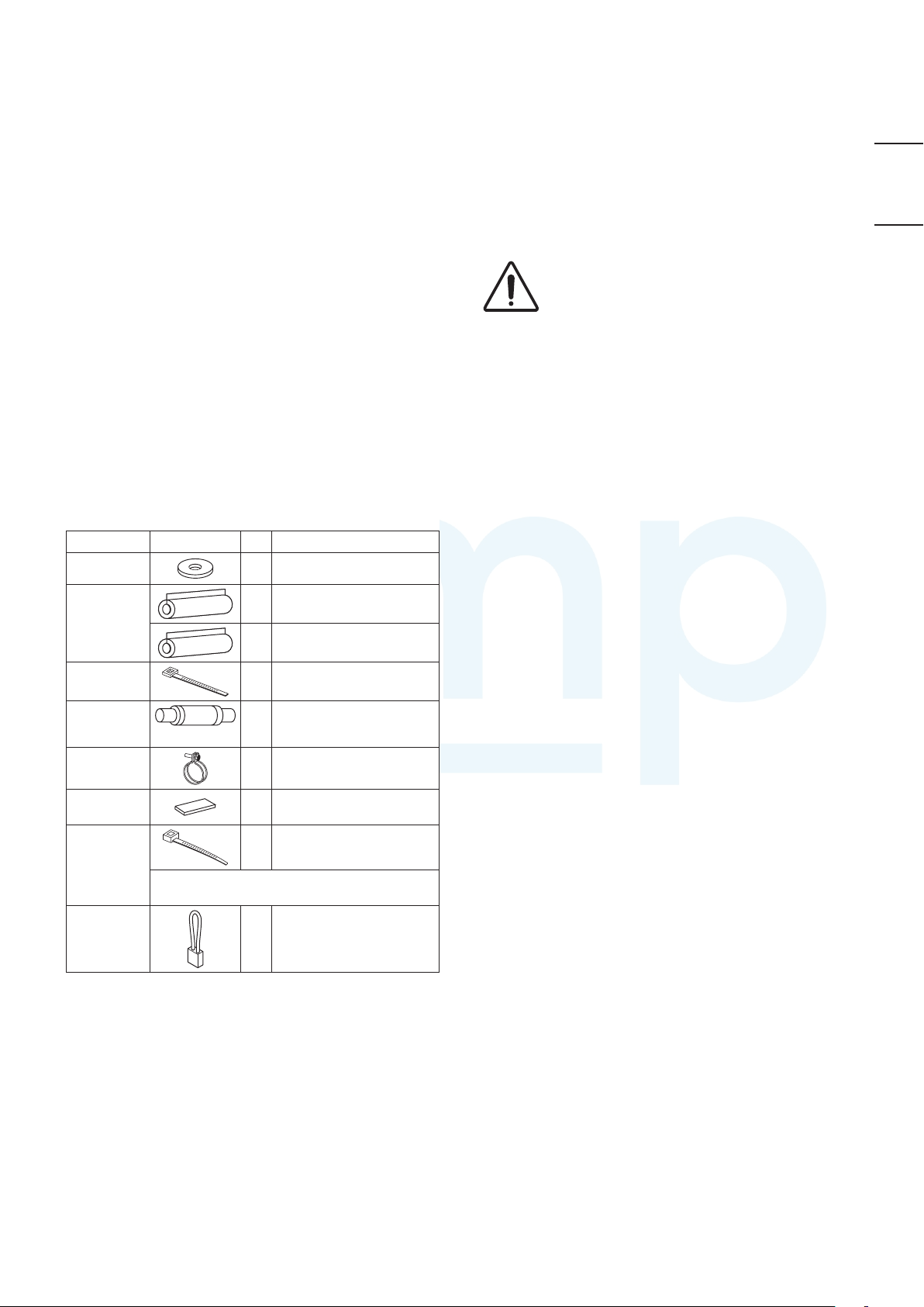
1-2. Accessories Supplied with Unit
Part Name Figure Q’ty Remarks
1-3. Type of Copper Tube and Insulation Material
If you wish to purchase these materials separately from a local
source, you will need:
1. Deoxidized annealed copper tube for refrigerant tubing.
2. Foamed polyethylene insulation for copper tubes as
required to precise length of tubing. Wall thickness of the
insulation should be not less than 5/16”(8 mm).
3. Use insulated copper wire for field wiring. Wire size varies
with the total length of wiring. Refer to 4. ELECTRICAL
WIRING for details.
CAUTION
Check local electrical codes and regulations before
obtaining wire. Also, check any specified instructions or
limitations.
1-4. Additional Materials Required for Installation
1. Refrigeration (armored) tape
2. Insulated staples or clamps for connecting wire (See your
local codes.)
3. Putty
4. Refrigeration tubing lubricant
5. Clamps or saddles to secure refrigerant tubing
6. Scale for weighing
ENGLISH
Washer
Flare
insulator
Clamper
Drain hose
Hose band
Drain hose
insulation
Clamper
Short-circuit
connection
• Use 3/8”(M10) for suspension bolts.
• Suspension bolts and nuts are field supply.
L=131
Be sure to fix the power supply cord
with the clamper.
8 For suspension fitting
For gas pipe / liquid pipe
2
connection
For gas pipe / liquid pipe
2
connection
For flare / drain insulating
4
connection
For unit & PVC pipe
1
connection
1 For drain hose connection
2 For drain pipe connection
1 For power supply code
For high static pressure
(Located on the back of
1
the electrical component
box lid.)
5

2. SELECTING THE INSTALLATION SITE
AMP Air Conditioning
www.ampair.co.uk | sales@ampair.co.uk
Indoor Unit
AVOID:
● areas where leakage of flammable gas may be expected.
● places where large amounts of oil mist exist.
● direct sunlight.
● locations near heat sources which may affect the
performance of the unit.
● locations where external air may enter the room directly.
This may cause “condensation” on the air discharge ports,
causing them to spray or drip water.
● locations where the remote controller will be splashed with
water or affected by dampness or humidity.
● installing the remote controller behind curtains or furniture.
● locations where high-frequency emissions are generated.
DO:
● select an appropriate position from which every corner of the
room can be uniformly cooled.
● select a location where the ceiling is strong enough to
support the weight of the unit.
● select a location where tubing and drain pipe have the
shortest run to the outdoor unit.
● allow room for operation and maintenance as well as
unrestricted air flow around the unit.
● install the unit within the maximum elevation difference
above or below the outdoor unit and within a total tubing
length (L) from the outdoor unit as detailed in the installation
manual packed with the outdoor unit.
● allow room for mounting the remote controller about 1 m (3.3
ft.) off the floor, in an area that is not in direct sunlight nor in
the flow of cool air from the indoor unit.
● The elevation (Slim Low Static Ducted) between the bottom
unit and the floor surface should be at least 2.4 m (8 feet).
● If the elevation (Slim Low Static Ducted) between them is
less than 2.4 m (8 feet), install a filter or a protective device
(field supply) not to touch the electrical parts or fan with
hands.
2.4 m (8 feet) or more
Floor
Fig. 2-1
6
3. HOW TO INSTALL THE INDOOR UNIT
640
AMP Air Conditioning
www.ampair.co.uk | sales@ampair.co.uk
Slim Low Static Ducted Type (Type M1)
■
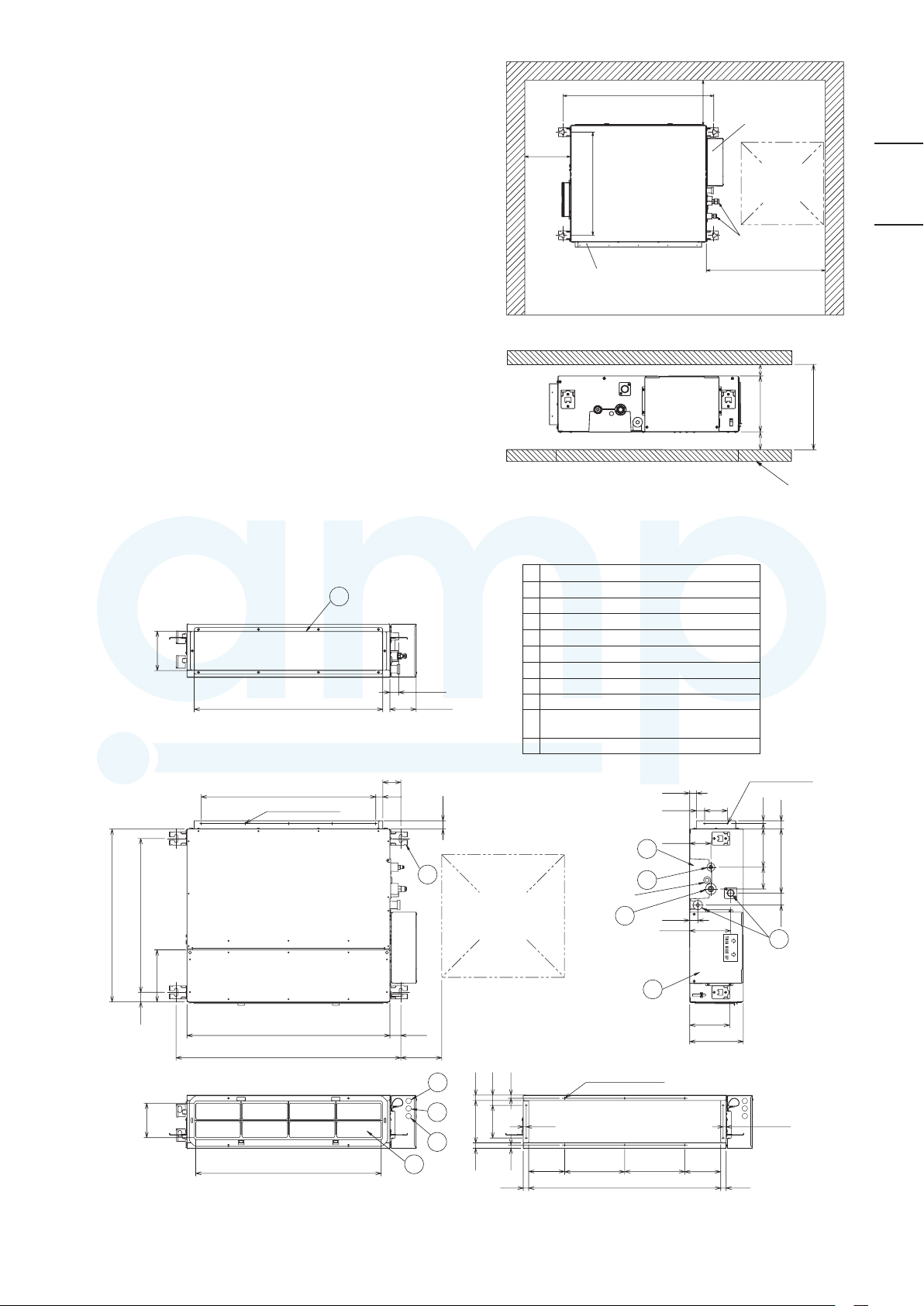
3-1. Required Minimum Space for Installation and
Service
● This air conditioner is usually installed above the ceiling so
that the indoor unit and ducts are not visible. Only the air
intake and air outlet ports are visible from below.
● The minimum space for installation and service is shown in
the diagram. (Fig. 3-1)
● *H dimension means the minimum height of the unit.
● Select the *H dimension such that a downward slope of at
least 1/100 is ensured as indicated in “3-6. Installing the
Drain Pipe”.
● The diagram shows the detailed dimensions of the indoor
unit. (Fig. 3-2)
824(Suspension bolt pitch)
Min.
200
or
more
Min. 200
or more
Min. 100 mm or more for bottom air intake
564
Refrigerant tubing
Min. 650 or more
Flange for air
outlet duct
Min. 20 or more
Min. 20 or more
Electrical
component box
Inspection
access
450x450
Unit: mm
200
*H=Min. 240
Ceiling
ENGLISH
Fig. 3-1
Flange for air outlet duct
564 (Suspension bolt pitch)
145
194
6
692
(Flange for air outlet duct)
640 (160x4)
5-ø3.1(Hole)
66
26
29
96
27
4
Inspection access
(450x450)
(Field supply)
Refrigerant tubing joint (narrow tube)
1
Refrigerant tubing joint (wide tube)
2
Upper and bottom drain port (O.D.26 mm)
3
Suspension lug
4
Power supply outlet (ø17)
5
Flange for air outlet duct
6
Cover plate
7
Electrical component box
8
Filter
9
Inter-unit control wiring and control wiring for
0
group control outlet (ø15)
Remote control wiring outlet (ø15)
!
7
1
Water inlet
2
153
8
28
30
81
33
Unit : mm
84
2-ø3.1(Hole)
30
10
23844
80 143
3
38
(Suspension bolt pitch)
126
750
824
680
37
150
9
10
11
150
200
5
22
14
40
14
120
15523
132
15
23
10-ø3.1(Hole)
220
* Filter Uninstalled
220
704
14
132
23
Fig. 3-2
7

3-2. Preparations Before Installation
AMP Air Conditioning
www.ampair.co.uk | sales@ampair.co.uk
(1) Confirm the positional relationship between the unit and
suspension bolts. (Fig. 3-3)
Install the inspection opening on the control box side where
●
maintenance and inspection of the control box and drain
pump are easy. Install the inspection opening also in the
lower part of the unit.
Air discharge Air intake
A
(Inspection access)
Ceiling
3-3. For Bottom Intake
For bottom intake, replace the cover plate and Frame Filter
Assy net in the procedure shown in the diagram.
(1) Remove the frame filter assy.
Remove the cover plate. (Fig. 3-4)
Air intake
Frame
Filter Assy
Cover plate
700
Allow view A
Inspection access
(Field supply)
(2) Make sure the range of the unit’s external static pressure is
not exceeded.
(See the technical documentation for the range of the external
static pressure setting.)
(3) Open the installation hole. (Pre-set ceilings)
Once the installation hole is opened in the ceiling where the
●
unit is to be installed, pass refrigerant piping, drain piping,
inter-unit control wiring, and remote controller wiring to the
unit’s piping and wiring holes.
See “5. HOW TO PROCESS TUBING”, “3-6. Installing the
Drain Pipe” and “4. ELECTRICAL WIRING”.
After opening the ceiling hole, make sure ceiling is level if
●
needed. It might be necessary to reinforce the ceiling frame
to prevent shaking.
Consult an architect or carpenter for details.
800
Unit: mm
Fig. 3-3
Air discharge
Dummy hole
Fig. 3-4
(2) Refer to the diagram to attach the cover plate and frame filter
assy in the direction of the arrow. (Fig. 3-5)
Note: Attach the cover plate with the dummy holes downward.
Dummy hole
Cover plate
Frame
Filter Assy
Air discharge
Air intake
Fig. 3-5
(3) Attach the frame filter assy (supplied) in the manner shown in
the diagram. (Fig. 3-6)
Main unit
Attach the Frame Filter Assy to
the main unit while pushing the
tip of the latches in the direction
of the arrow.
Frame Filter Assy
In case of bottom side In case of back side
Fig. 3-6
8
 Loading...