

Panasonic s-26pk2u6 installation
INSTALLATION INSTRUCTIONS
Air Conditioner
This air conditioner uses the refrigerant R410A.
Model No.
Indoor Units
Type Indoor Unit Type
K2 Wall Mounted S-26PK2U6
Nominal Capacity
26
Read through the Installation Instructions before you proceed with the installation.
In particular, you will need to read under the “IMPORTANT!” section at the top of the page.
85464369877010
CV6233320502
IMPORTANT!
Please Read Before Starting
This air conditioning system meets strict safety and
operating standards. As the installer or service person, it is
an important part of your job to install or service the
system so it operates safely and efficiently.
For safe installation and trouble-free operation, you
must:
● Carefully read this instruction booklet before beginning.
● Follow each installation or repair step exactly as shown.
● This air conditioner shall be installed in accordance with
National Wiring Regulations.
● Pay close attention to all warning and caution notices
given in this manual.
This symbol refers to a hazard or
WARNING
CAUTION
If Necessary, Get Help
These instructions are all you need for most installation
sites and maintenance conditions. If you require help for a
special problem, contact our sales/service outlet or your
certified dealer for additional instructions.
In Case of Improper Installation
The manufacturer shall in no way be responsible for
improper installation or maintenance service, including
failure to follow the instructions in this document.
SPECIAL PRECAUTIONS
WARNING
ELECTRICAL SHOCK CAN CAUSE
SEVERE PERSONAL INJURY OR DEATH.
ONLY A QUALIFIED, EXPERIENCED
ELECTRICIAN SHOULD ATTEMPT TO
WIRE THIS SYSTEM.
• Do not supply power to the unit until all wiring and tubing
are completed or reconnected and checked.
• Highly dangerous electrical voltages are used in this system.
Carefully refer to the wiring diagram and these instructions
when wiring. Improper connections and inadequate
grounding can cause accidental injury or death.
• Ground the unit following local electrical codes.
• Connect all wiring tightly. Loose wiring may cause over-
heating at connection points and a possible fire hazard.
• To prevent possible hazards from insulation failure,
the unit must be grounded.
• This equipment is strongly recommended to be installed
with Earth Leakage Circuit Breaker (ELCB) or Residual
Current Device (RCD). Otherwise, it may cause electrical
shock and fire in case of equipment breakdown or
insulation breakdown.
unsafe practice which can result
in severe personal injury or death.
This symbol refers to a hazard or
unsafe practice which can result
in personal injury or product or
property damage.
When Wiring
When Transporting
Be careful when picking up and moving the indoor and
outdoor units. Get a partner to help, and bend your knees
when lifting to reduce strain on your back. Sharp edges or
thin aluminum fins on the air conditioner can cut your
fingers.
When Installing…
Select an installation location which is rigid and strong
enough to support or hold the unit, and select a location for
easy maintenance.
…In a Room
Properly insulate any tubing run inside a room to prevent
“sweating” that can cause dripping and water damage to
walls and floors.
Keep the fire alarm and the air
CAUTION
…In Moist or Uneven Locations
Use a raised concrete pad or concrete blocks to provide a
solid, level foundation for the outdoor unit. This prevents
water damage and abnormal vibration.
…In an Area with High Winds
Securely anchor the outdoor unit down with bolts and a
metal frame. Provide a suitable air baffle.
…In a Snowy Area (for Heat Pump-type Systems)
Install the outdoor unit on a raised platform that is higher
than drifting snow. Provide snow vents.
outlet at least 5 feet (1.5 m) away
from the unit.
When Connecting Refrigerant Tubing
• Pay particular attention to refrigerant leakages.
• Ventilate the room immediately, in the event that is
refrigerant gas leaks during the installation. Be careful not
to allow contact of the refrigerant gas with a flame as this
will cause the generation of toxic gas.
• Keep all tubing runs as short as possible.
• Apply refrigerant lubricant to the matching surfaces of the
flare and union tubes before connecting them, then tighten
the nut with a torque wrench for a leak-free connection.
• Check carefully for leaks before starting the test run.
WARNING
• When performing piping work, do not mix air
except for specified refrigerant (R410A) in
refrigeration cycle. It causes capacity down, and
risk of explosion and injury due to high tension
inside the refrigerant cycle.
• If the refrigerant comes in contact with a flame,
it produces a toxic gas.
• Do not add or replace refrigerant other than
specified type. It may cause product damage,
burst and injury, etc.
2
• Do not leak refrigerant while piping work for an
installation or re-installation, and while repairing
refrigeration parts.
Handle liquid refrigerant carefully as it may cause
frostbite.
When Servicing
• Turn the power OFF at the main power box (mains)
before opening the unit to check or repair electrical
parts and wiring.
• Keep your fingers and clothing away from any moving
parts.
• Clean up the site after you finish, remembering to
check that no metal scraps or bits of wiring have been
left inside the unit.
CAUTION
• Do not touch the air inlet or the sharp
aluminum fins of the outdoor unit. You
may get injured.
• Ventilate any enclosed areas when installing or
testing the refrigeration system. Leaked
refrigerant gas, on contact with fire or heat, can
produce dangerously toxic gas.
• Confirm after installation that no refrigerant gas
is leaking. If the gas comes in contact with a
burning stove, gas water heater, electric room
heater or other heat source, it can cause the
generation of toxic gas.
WARNING
Others
• This product must not be modified or
disassembled under any circumstances.
Modified or disassembled unit may cause fire,
electric shock or injury.
• Do not clean inside the indoor and outdoor
units by users. Engage authorized dealer or
specialist for cleaning.
• In case of malfunction of this appliance, do
not repair by yourself. Contact to the sales
dealer or service dealer for a repair.
NOTICE • This device complies with part 15 of the FCC Rules.
Operation is subject to the following two conditions:
(1) This device may not cause harmful interference, and (2) this device must accept any interference
received, including interference that may cause undesired operation.
• This equipment has been tested and found to comply with the limits for a Class B digital device,
pursuant to part 15 of the FCC Rules.
These limits are designed to provide reasonable protection against harmful interference in a residential
installation. This equipment generates, uses and can radiate radio frequency energy and, if not installed
and used in accordance with the instructions, may cause harmful interference to radio communications.
However, there is no guarantee that interference will not occur in a particular installation. If this
equipment does cause harmful interference to radio or television reception, which can be determined by
turning the equipment off and on, the user is encouraged to try to correct the interference by one or
more of the following measures:
• Reorient or relocate the receiving antenna.
• Increase the separation between the equipment and receiver.
• Connect the equipment into an outlet on a circuit different from that to which the receiver is connected.
• Consult the dealer or an experienced radio/TV technician for help.
• FCC Caution: To assure continued compliance, follow the attached installation instructions.
Any changes or modifications not expressly approved by the party responsible for compliance could void
the user’s authority to operate this equipment.
WARNING
• Do not sit or step on the unit, you may
fall down accidentally.
CAUTION
• Do not touch the air inlet or the sharp
aluminum fins of the outdoor unit.
You may get injured.
• Do not stick any object into the FAN
CASE.
You may be injured and the unit may
be damaged.
3

Check of Density Limit
The room in which the air conditioner is to be
installed requires a design that in the event of
refrigerant gas leaking out, its density will not
exceed a set limit.
The refrigerant (R410A), which is used in the air
conditioner, is safe, without the toxicity or combustibility
of ammonia, and is not restricted by laws imposed to
protect the ozone layer. However, since it contains more
than air, it poses the risk of suffocation if its density
should rise excessively. Suffocation from leakage of
refrigerant is almost non-existent. With the recent
increase in the number of high density buildings,
however, the installation of multi air conditioner systems
is on the increase because of the need for effective use
of floor space, individual control, energy conservation by
curtailing heat and carrying power, etc.
Most importantly, the multi air conditioner system is able
to replenish a large amount of refrigerant compared to
conventional individual air conditioners.
If a single unit of the multi air conditioner system is to be
installed in a small room, select a suitable model and
installation procedure so that if the refrigerant
accidentally leaks out, its density does not reach the
limit (and in the event of an emergency, measures can
be made before injury can occur).
ASHRAE and the International Mechanical Code of the
ICC as well as CSA provide guidance and define
safeguards related to the use of refrigerants, all of which
define a Refrigerant Concentration Level (RCL) of
25 pounds (11.3 kg) per 1,000 cubic feet (28.3 m3) for
R410A refrigerant.
For additional guidance and precautions related to
refrigerant safety, please refer to the following
documents:
International Mechanical Code 2012 (IMC-2012)
(or more recently revised)
ASHRAE 15
ASHRAE 34
4

CONTENTS
Page Page
IMPORTANT . . . . . . . . . . . . . . . . . . . . . . . . . . . . . . . . . . . . . . 2
Please Read Before Starting
Check of Density Limit
1. GENERAL . . . . . . . . . . . . . . . . . . . . . . . . . . . . . . . . . . . . . 6
1-1. Tools Required for Installation (not supplied)
1-2. Accessories Supplied with Unit
1-3. Type of Copper Tube and Insulation Material
1-4. Additional Materials Required for Installation
2. SELECTING THE INSTALLATION SITE . . . . . . . . . . . . . . 7
2-1. Indoor Unit
3. HOW TO INSTALL THE INDOOR UNIT . . . . . . . . . . . . . . 8
3-1. Remove the Rear Panel from the Unit
3-2. Make a Hole
3-3. Install the Rear Panel on the Wall
3-4. Removing and Installing the Grille
3-5. Shape the Indoor Side Tubing
3-6. Wiring Instructions
3-7. Mounting
3-8. Drain Hose
4. ELECTRICAL WIRING . . . . . . . . . . . . . . . . . . . . . . . . . . 15
4-1. General Precautions on Wiring
4-2. Recommended Wire Length and Wire Diameter for
Power Supply System
4-3. Wiring System Diagrams
7. PRECAUTIONS ON TEST RUN . . . . . . . . . . . . . . . . . . . 21
Checkpoint . . . . . . . . . . . . . . . . . . . . . . . . . . . . . . . . . . . . 21
■
8. HOW TO INSTALL THE WIRELESS REMOTE
CONTROLLER . . . . . . . . . . . . . . . . . . . . . . . . . . . . . . . . 22
8-1. Wireless Remote Controller Installation
8-2. Room Temperature Sensor Setting
8-3. Address Switches
8-4. Misoperation Alarm Indicators
8-5. Basic Wiring Diagram
8-6. Wiring System Diagram for Group Control
8-7. Wiring System Diagram for Multiple Remote
Controllers
8-8. Test Run Procedure
8-9 Preparing for the Test Run
8-10. When Setting Indoor Unit Control PCB Switch for Wall
Mounted Indoor Unit
8-11. Diagnosis Table
9. APPENDIX . . . . . . . . . . . . . . . . . . . . . . . . . . . . . . . . . . . 32
Name of Parts
■
Care and Cleaning
■
Troubleshooting
■
Tips for Energy Saving
■
5. HOW TO PROCESS TUBING . . . . . . . . . . . . . . . . . . . . . 18
5-1. Connecting the Refrigerant Tubing
5-2. Connecting Tubing Between Indoor and Outdoor Units
5-3. Insulating the Refrigerant Tubing
5-4. Taping the Tubes
5-5. Finishing the Installation
6. HOW TO INSTALL THE TIMER REMOTE CONTROLLER
OR HIGH-SPEC WIRED
REMOTE CONTROLLER (OPTIONAL PART) . . . . . . . . 20
N OT E
Refer to the Operating Instructions attached to the optional
Timer Remote Controller or optional High-spec Wired
Remote Controller.
5
1. GENERAL
This booklet briefly outlines where and how to install the
air conditioning system. Please read over the entire set of
instructions for the indoor and outdoor units and make sure all
accessory parts listed are with the system before beginning.
1-1. Tools Required for Installation (not supplied)
1. Flathead screwdriver
2. Phillips head screwdriver
3. Knife or wire stripper
4. Tape measure
5. Carpenter’s level
6. Sabre saw or keyhole saw
7. Hacksaw
8. Core bits
9. Hammer
10. Drill
11. Tube cutter
12. Tube flaring tool
13. Torque wrench
14. Adjustable wrench
15. Reamer (for deburring)
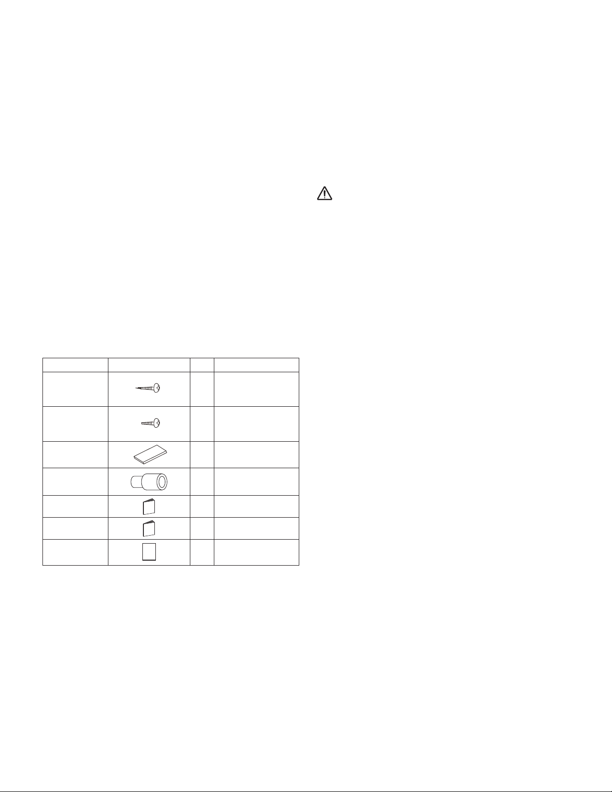
1-2. Accessories Supplied with Unit
1-3.Type of Copper Tube and Insulation Material
If you wish to purchase these materials separately from a local
source, you will need:
1. Deoxidized annealed copper tube for refrigerant tubing.
Cut each tube to the appropriate lengths +11-13/16
to 15-6/8
2. Foamed polyethylene insulation for copper tubes as required
to precise length of tubing. Wall thickness of the insulation
should be not less than 5/16
3. Use insulated copper wire for field wiring. Wire size varies with
the total length of wiring. See the section “ 4. ELECTRICAL
WIRING” for details.
CAUTION
Check local electrical codes and regulations before obtaining
wire. Also, check any specified instructions or limitations.
(40 cm) to dampen vibration between units.
"
(8 mm).
"
(30 cm)
"
1-4. Additional Materials Required for Installation
1. Refrigeration (armored) tape
2. Insulated staples or clamps for connecting wire (See your local
codes.)
3. Putty
4. Refrigeration tubing lubricant
5. Clamps or saddles to secure refrigerant tubing
6. Scale for weighing
Table 1-1 (Wall Mounted)
Part Name Figure
Tapping screw 8
Tapping screw
Flare
insulation
Drain hose
adapter
Operating
Instructions
Installation
Instructions
Warranty
card
Q’ty
Remarks
Truss-head Phillips
5/32" × 13/16"
(4 × 20 mm)
Truss-head Phillips
2
5/32" × 13/32"
(4 × 10 mm)
1
1
1
1
1
6
2. SELECTING THE INSTALLATION SITE
Wall Mounted
2-1. Indoor Unit
AVOID:
● areas where leakage of flammable gas may be expected.
● places where large amounts of oil mist exist.
● direct sunlight.
● locations near heat sources which may affect the
performance of the unit.
● locations where external air may enter the room directly.
This may cause “condensation” on the air discharge ports,
causing them to spray or drip water.
● locations where the remote controller will be splashed with
water or affected by dampness or humidity.
● installing the remote controller behind curtains or furniture.
● locations where high-frequency emissions are generated.
DO:
● select an appropriate position from which every corner of the
room can be uniformly cooled.
● select a location where the ceiling is strong enough to
support the weight of the unit.
WARNING
● select a location which can support a load that is four times
the indoor unit weight.
● select a location where tubing and drain pipe have the
shortest run to the outdoor unit.
● allow room for operation and maintenance as well as
unrestricted air flow around the unit.
● install the unit within the maximum elevation difference
above or below the outdoor unit and within a total tubing
length (L) from the outdoor unit as detailed in the Installation
I
nstructions packed with the outdoor unit.
●
allow room for mounting the remote controller about 3.3 ft. (1 m)
off the floor, in an area that is not in direct sunlight or in the flow
of cool air from the indoor unit.
N OT E
Air delivery will be degraded if the distance from the floor to the
ceiling is greater than 9.8 ft. (3 m).
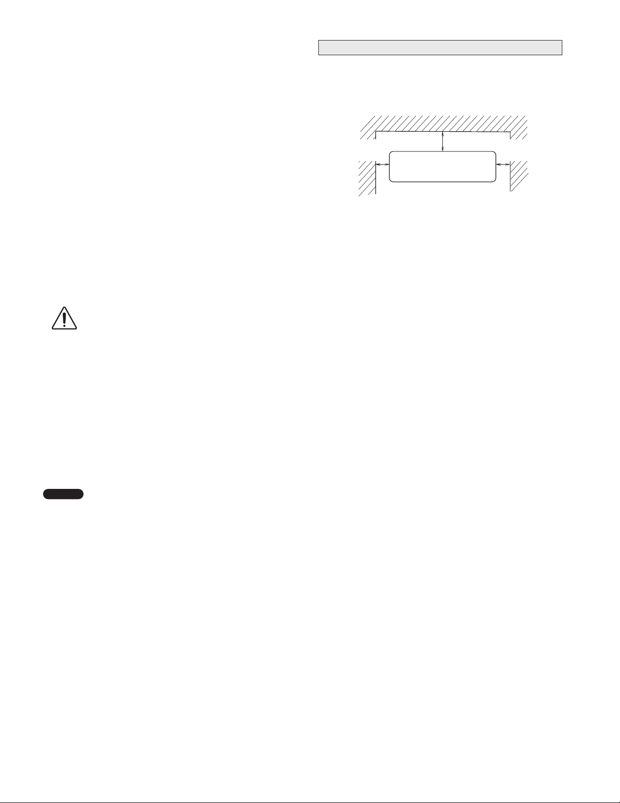
The air inlet and outlet of the indoor unit must be free of any
obstructions to allow air to spread throughout the room.
1. The indoor unit must be within a maintenance soace.
min.
2
" (5 cm)
min. 3" (7.5 cm)
min.
2
" (5 cm)
Front View
Fig. 2-1
7
3. HOW TO INSTALL THE INDOOR UNIT
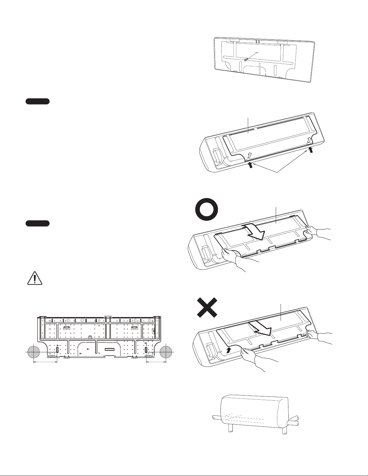
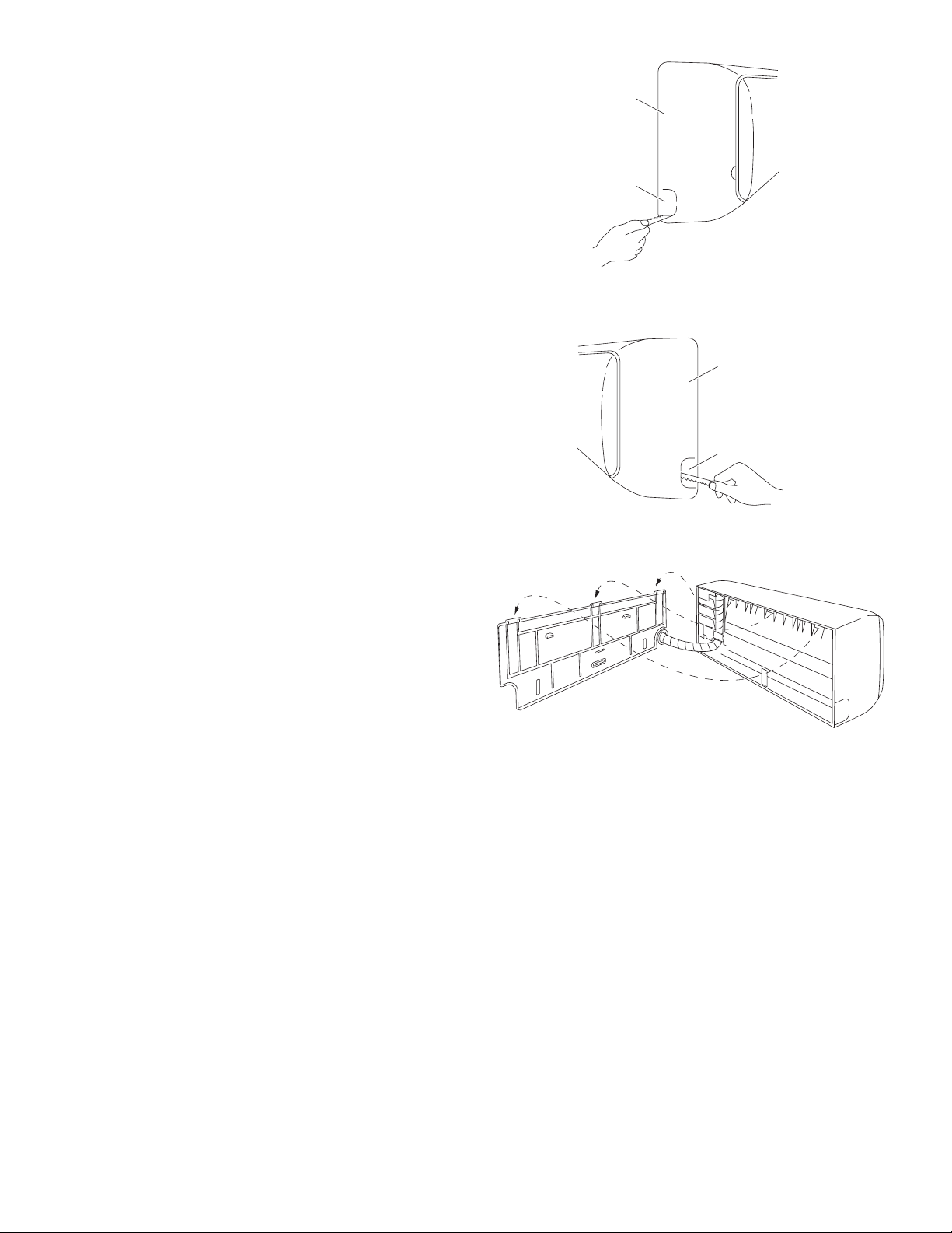
3-1. Remove the Rear Panel from the Unit
(1) Remove and discard the set screw on the rear panel.
(Fig. 3-1)
(2) Press the 2 marks on the frame cover and disengage the
stationary tabs from the frame. (Fig. 3-2)
(3) Remove the rear panel by grasping the sections shown in
Fig. 3-3 and pulling it in the direction shown by the arrow.
N OT E
Tubing can be extended in 6 directions as shown in Fig. 3-5.
Select the direction you need providing the shortest run to the
outside unit.
● When left tubing is to be done, switch the drain hose and
drain cap. (For details, see the section “Switching drain hose
and drain cap” on page 13.)
3-2. Make a Hole
(1) Place the rear panel from the indoor unit on the wall at the
location selected. Make sure the panel is horizontal, using a
carpenter’s level or tape measure to measure down from the
ceiling. Wait until after cutting the hole before attaching the
rear panel to the wall.
(2) Determine which side of the unit you should make the hole for
tubing and wiring. (Fig. 3-6)
Set screw only for transportation
Fig. 3-1
Rear panel
marks
Fig. 3-2
Rear panel
N OT E
In the case of left-rear tubing, use the measurement points
158 mm from the marked position on the rear panel for precise
placement of the hose outlet. (Fig. 3-6)
(3) Before making the hole, check carefully that no studs or pipes
are directly run behind the spot to be cut.
Also avoid areas where
CAUTION
electrical wiring or conduits
are located.
The above precautions are also applicable if tubing goes
through the wall in any other location.
6-7/32" (158 mm)
5-3/16" (132 mm)
Unit: inch (mm)
Fig. 3-6
Fig. 3-3
Rear panel
Fig. 3-4
8
Left tubing
Left-downward tubing
Left-rear
tubing
Right-rear tubing
(recommended)
Right tubing
Right-downward tubing
Fig. 3-5
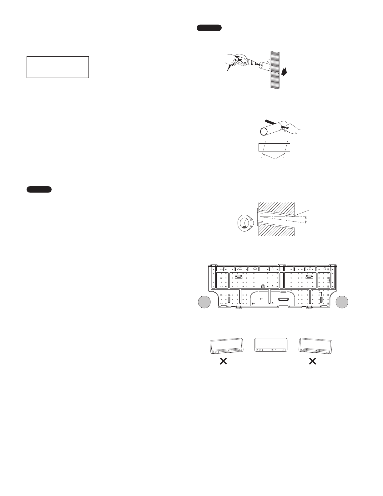
(4) Using a sabre saw, keyhole saw or hole-cutting drill
attachment, cut a hole in the wall. See Table 3-1 and
Fig. 3-7.
Table 3-1
Hole Dia.
3-5/32" (80 mm)
(5) Measure the thickness of the wall from the inside edge to the
outside edge and cut PVC pipe at a slight angle 1/4" (6 mm)
shorter than the thickness of the wall. (Fig. 3-8)
(6) Place the plastic cover over the end of the pipe (for indoor side
only) and insert the pipe in the wall. (Fig. 3-9)
3-3. Install the Rear Panel on the Wall
Be sure to confirm that the wall is strong enough to suspend the
unit.
There are a number of screw holes on the rear panel.
Using the 8 screw holes with mark is recommended to attach
the rear panel securely to the wall.
N OT E
Hole should be made at a slight downward slant to the outdoor
side.
Indoor
side
Outdoor
side
Fig. 3-7
PVC pipe (Locally purchased)
Cut at slight angle
Fig. 3-8
N OT E
Be sure to install the unit within the range of the wall.
If Wooden Wall
(1) Attach the rear panel to the wall with the 8 screws provided.
(Fig. 3-10)
If you are not able to line up the holes in the rear panel with
the beam locations marked on the wall, use rawl plugs or
toggle bolts to go through the holes on the panel or drill 3/16"
(5 mm) dia. holes in the panel over the stud locations and then
mount the rear panel.
(2) Double check with a carpenter’s level or tape measure that the
panel is level. This is important to install the unit properly. (Fig.
3-11)
(3) Make sure the panel is flush against the wall. Any space
between the wall and unit will cause noise and vibration.
INSIDE OUTSIDE
Plastic cover
(Locally purchased)
Wall
PVC pipe
Slight
angle
Fig. 3-9
Fig. 3-10
Fig. 3-11
9
3-4. Removing and Installing the Grille
Basically, these models can be installed and wired without
removing the grille. If access to any internal part is needed,
follow the steps as given below.
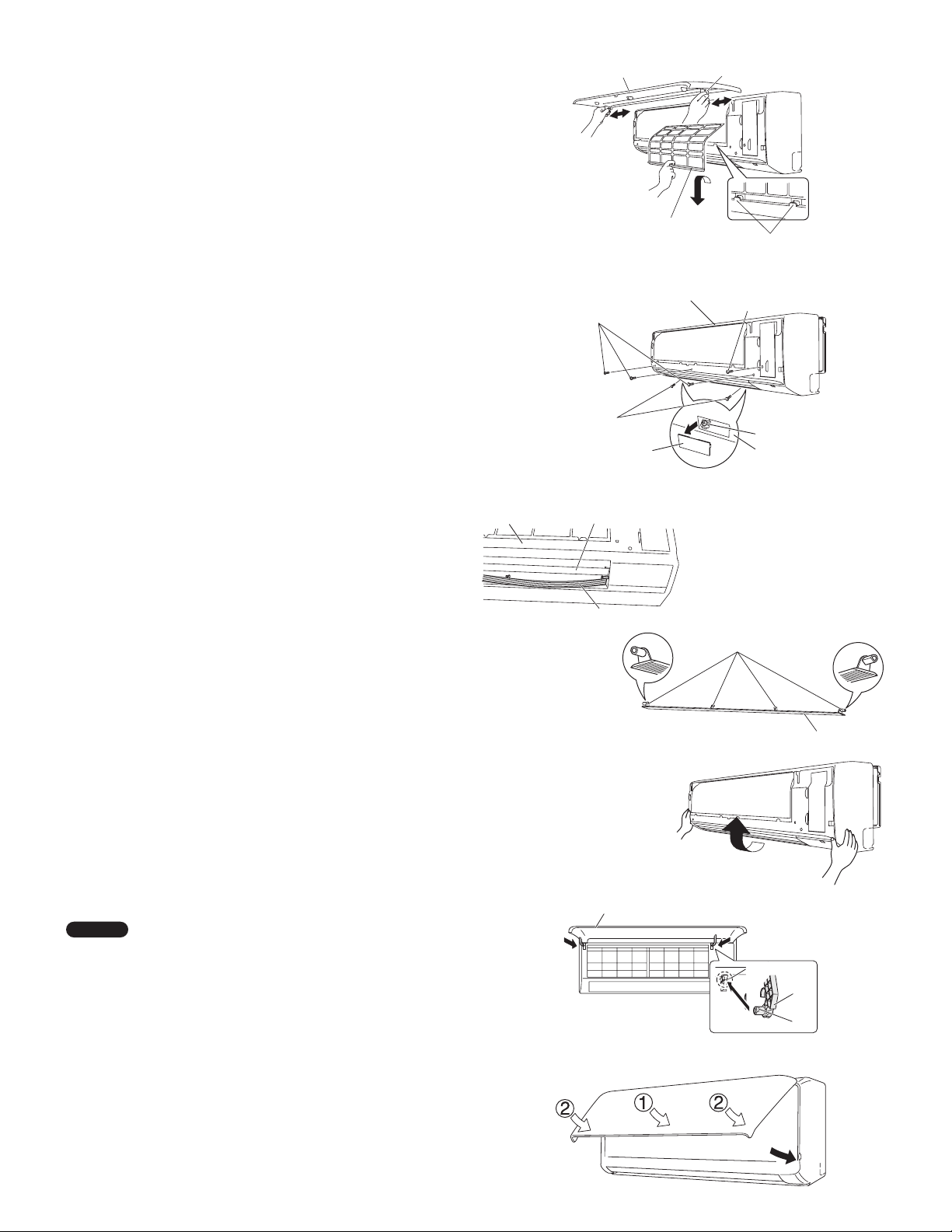
How to remove the grille
(1) Open the front panel until it is nearly horizontal, grasp the
sections near the front panel arms on both sides, and then
remove the panel by pushing the arms towards the outside
while pulling the panel towards you.
If the front panel is difficult to remove, grasp both ends of it
and lift it up slightly. Move it to the left and disengage the left
arm, then move it to the right and disengage the right arm.
(Fig. 3-12)
(2) Lift the anti-mold filter up slightly to disengage it from the
protrusions on the unit, and then pull downward to remove the
filter from the unit. (Fig. 3-12)
(3) Remove the 3 screws from the front of the unit and remove
the screw covers on the bottom surface. Then remove the 2
screws. (Fig. 3-13)
(4) Remove the screw on the right side cover plate and remove
the cover. (Fig. 3-13)
(5) Remove the lower flap by disengaging 4 pins of the lower flap
in order. (Figs. 3-14 and 3-15)
(The flap is so flexible that it can be easily removed.)
(6) Lift up the grille in the direction shown by the arrow and pull
the grille towards you to remove it. (Fig. 3-16)
How to replace the grille
(1) While aligning the top edge of the grille with the frame, move
the grille horizontally and insert the top and bottom into the
frame.
(2) Press the grille firmly with your hand to ensure no gap exists
between the frame and grille.
(3) Tighten the 6 screws. And fix the removed covers in place.
(4) Grasp the sections near the front panel arms on both sides,
and hold the front panel so that it is nearly horizontal. Push the
arm shafts towards the outside so that they come into contact
with the top of the indentations on the right and left sides of the
air conditioner. Then push firmly until the arm shafts click into
place. (Fig. 3-17)
(5) Remount the lower flap.
(In remounting the flap, it cannot be turned end for end
because the right and left pins of the flap differ in form.
(Fig. 3-15))
(6) Insert the top of the anti-mold filter, and then secure the
bottom of the filter with the protrusions on the unit.
(7) When closing the front panel, push the central part of the front
panel first and then press the bottom right and left corners in
place until you feel a click. (Fig. 3-18)
N OT E
Check that no gap exists between the frame and the grille.
Screw (on the bottom)
Grille
Fig. 3-14
Front panel
Anti-mold filter
Screw (on the front)
Screw cover
Upper flap
Lower flap
Front panel
Grille
Arm
Protrusions
Screw (on the cover)
Screw
Bottom surface
Pin
Fig. 3-15
Indentation
Fig. 3-12
Fig. 3-13
Lower flap
Fig. 3-16
Arm
10
Pin
Fig. 3-17
Fig. 3-18
3-5. Shape the Indoor Side Tubing
(1) Arrangement of tubing by direction
a) Right or left tubing
Cut out the corner of the right/left frame with a hacksaw or
the like. (Figs. 3-19 and 3-20)
b) Right-rear or left-rear tubing
In this case, the corner of the frame need not be cut.
(2) To mount the indoor unit on the rear panel:
Hang the 3 mounting slots of the unit on the upper tabs of
the rear panel. (Fig. 3-21)
Grille
Left tubing
outlet
3-6. Wiring Instructions
General precautions on wiring
(1) Before wiring, confirm the rated voltage of the unit as shown
on its nameplate, then carry out the wiring closely following
the wiring diagram.
(2) Provide a power outlet to be used exclusively for each
unit, with a power supply disconnect and circuit breaker for
overcurrent protection provided in the exclusive line.
(3) To prevent possible hazards due to insulation failure, the unit
must be grounded.
(4) Each wiring connection must be done tightly and in
accordance with the wiring system diagram. Wrong wiring
may cause the unit to misoperate or become damaged.
(5) Do not allow wiring to touch the refrigerant tubing,
compressor, or any moving parts of the fan.
(6) Unauthorized changes in the internal wiring can be very
dangerous. The manufacturer will accept no responsibility for
any damage or misoperation that occurs as a result of such
unauthorized changes.
Fig. 3-19
Grille
Right tubing
outlet
Fig. 3-20
11
Fig. 3-21
 Loading...