

Panasonic S24NKUA, S18NKUA Installation Manual
10. Installation Instruction
• IMPORTANT (only for S18NKUA)
This product has been designed and manufactured to meet ENERGY STAR® criteria for energy efficiency when
matched with appropriate coil components. However, proper refrigerant charge and proper air flow are critical to
archive rated capacity and efficiency. Installation of this product should follow the manufacturer’s refrigerant
charging and air flow instructions. Failure to confirm proper charge and airflow may reduce energy
efficiency and shorten equipment life.
10.1.1 Select the Best Location
10.1.1.1 Indoor Unit
• Do not install the unit in excessive oil fume areas
such as kitchens, workshops etc.
• There should not be any heat source or steam
near the unit.
• There should not be any obstacles blocking the air
circulation.
• A place where air circulation in the room is good.
• A place where drainage can be easily done.
• A place where noise prevention is taken into
consideration.
• Do not install the unit near a doorway.
• Ensure the spaces indicated by arrows from the
wall, ceiling, fence or other obstacles.
• Recommended installation height for indoor unit
shall be at least 8.2 ft.
10.1.1.2 Outdoor Unit
• If an awning is built over the unit to prevent direct
sunlight or rain, be careful that heat radiation from
the condenser is not obstructed.
• There should not be any animal or plant which
could be affected by hot air discharged.
• Keep the spaces indicated by arrows from wall,
ceiling, fence or other obstacles.
• Do not place any obstacles which may cause a
short circuit of the discharged air.
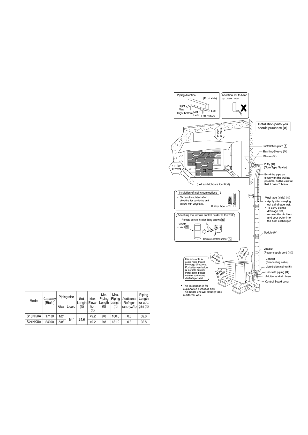
• If piping length is over the [piping length for
additional gas], additional refrigerant should be
added as shown in the table.
• Recommended installation height for outdoor unit
should be above the seasonal snow level.
Example: For S18NKUA
If the unit is installed at 41 ft distance, the quantity of
additional refrigerant should be 2.46 oz .... (41 - 32.8)
ft × 0.3 oz/ft = 2.46 oz.
10.1.2 Indoor/Outdoor Unit Installation
Diagram
19
10.1.3 Indoor Unit
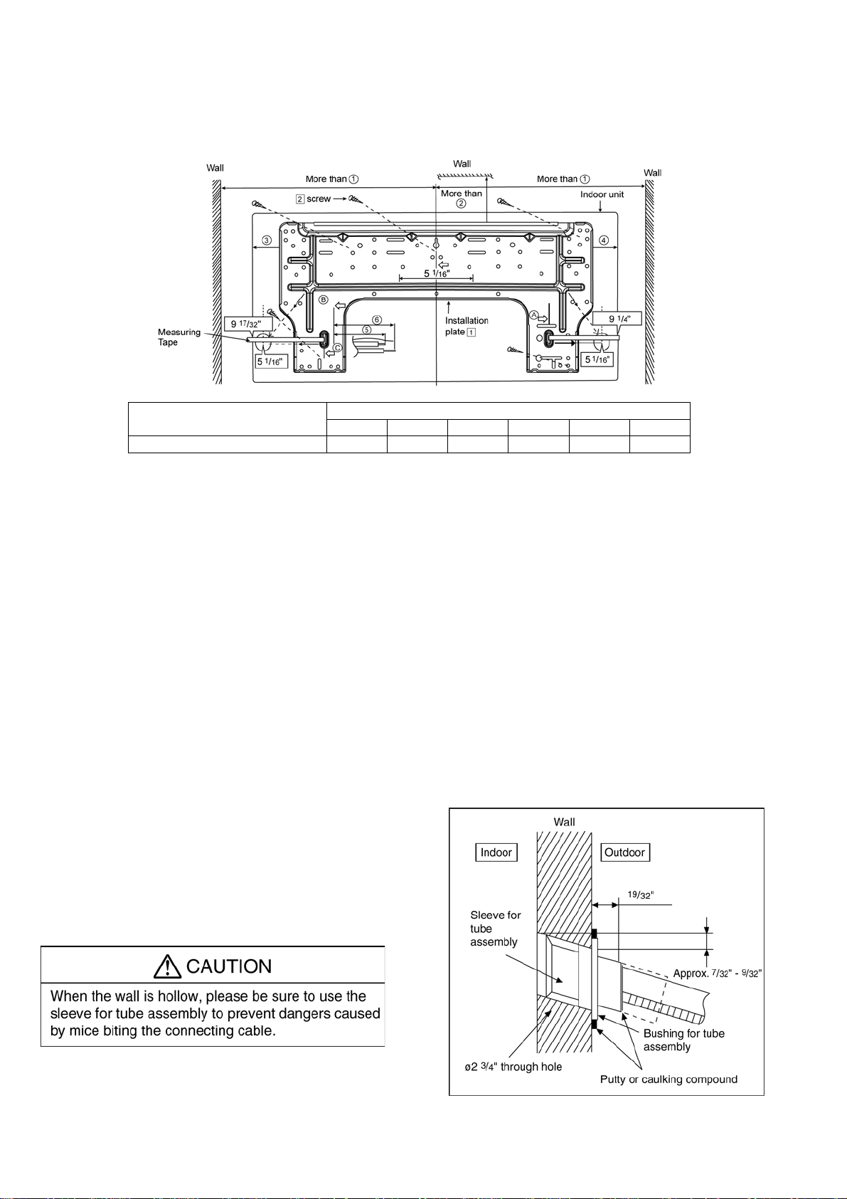
10.1.3.1 How to Fix Installation Plate
The mounting wall must be strong and solid enough to prevent if from the vibration.
Model
S18NKUA, S24NKUA 23 1/32” 3 7/32” 6 1/2” 6 7/32” 6 21/32” 8 5/8”
1
○
○2 ○3 ○4 ○5 ○6
Dimension
The centre of installation plate should be at more than c at right and left of the wall.
The distance from installation plate edge to ceiling should more than d.
From installation plate left edge to unit’s left side is e.
From installation plate right edge to unit’s right side is f.
B : For left side piping, piping connection for liquid should be about g from this line.
○
: For left side piping, piping connection for gas should be about h from this line.
1 Mount the installation plate on the wall with 5 screws or more (at least 5 screws).
(If mounting the unit on the concrete wall, consider using anchor bolts.)
o Always mount the installation plate horizontally by aligning the marking-off line with the thread and using
a level gauge.
2 Drill the piping plate hole with ø2 ¾” hole-core drill.
o Line according to the left and right side of the installation plate. The meeting point of the extended line is
the center of the hole. Another method is by putting measuring tape at position as shown in the diagram
above. The hole center is obtained by measuring the distance namely 5 1/16” for left and right hole
respectively.
o Drill the piping hole at either the right or the left and the hole should be slightly slanting to the outdoor
side.
10.1.3.2 To Drill a Hole in the Wall and
Install a Sleeve of Piping
1 Insert the piping sleeve to the hole.
2 Fix the bushing to the sleeve.
3 Cut the sleeve until it extrudes about 19/32”
from the wall.
4 Finish by sealing the sleeve with putty or
caulking compound at the final stage.
20
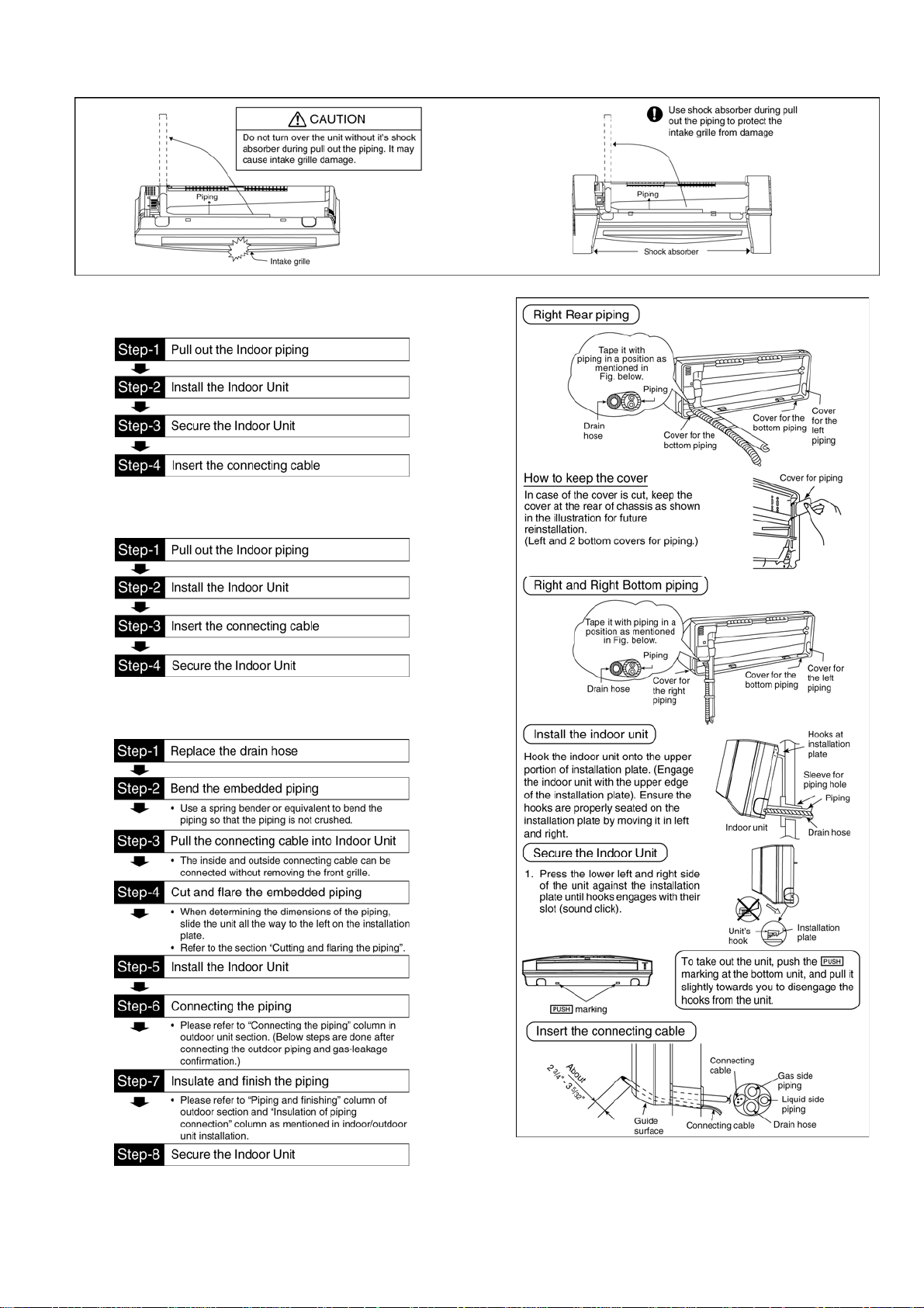
10.1.3.3 Indoor Unit Installation
10.1.3.4 For the right rear piping
10.1.3.5 For the right bottom piping
10.1.3.6 For the embedded piping
(This can be used for left rear piping and bottom
piping also.)
21
 Loading...