

Panasonic U-72ME2U9, U-96ME2U9, U-120ME2U9, U-144ME2U9, U-72ME2U94 installation
...
INSTALLATION INSTRUCTIONS
Air Conditioner
This air conditioner uses the refrigerant R410A.
NOTE
External diameter of service port R410A: 5/16" (7.94mm)
Model No.
Outdoor Units
Type Outdoor Unit Type Nominal Capacity
72 96 120 144
ME2 2WAY VRF System
U-72ME2U9 U-96ME2U9 U-120ME2U9 U-144ME2U9
U-72ME2U94 U-96ME2U94 U-120ME2U94 U-144ME2U94
• To be connecting Indoor Unit
Indoor Units
Type Indoor Unit Type
4-Way Cassette
U2
36" × 36"
4-Way Cassette
Y2
24" × 24"
D1 1-Way Cassette
Concealed Duct
F2
- Medium Static
Concealed Duct
M2
- Low Static
Concealed Duct
E1
- High Static
7 9 12 15 18 24 36 48 54
S-07MU2U6 S-09MU2U6 S-12MU2U6 S-24MU2U6 S-36MU2U6
S-07MY2U6 S-09MY2U6 S-12MY2U6 S-18MY2U6
S-07MD1U6 S-09MD1U6 S-12MD1U6
S-07MF2U6 S-09MF2U6 S-12MF2U6 S-15MF2U6 S-18MF2U6 S-24MF2U6 S-36MF2U6 S-48MF2U6 S-54MF2U6
S-07MM2U6 S-09MM2U6 S-12MM2U6 S-15MM2U6 S-18MM2U6
Nominal Capacity
S-36ME1U6 S-48ME1U6
T2 Ceiling
K2 Wall Mounted
P1 Floor Standing
Concealed Floor
R1
Standing
S-07MK2U6 S-09MK2U6 S-12MK2U6 S-18MK2U6 S-24MK2U6
S-07MP1U6 S-09MP1U6 S-12MP1U6 S-15MP1U6 S-18MP1U6 S-24MP1U6
S-07MR1U6 S-09MR1U6 S-12MR1U6 S-15MR1U6 S-18MR1U6 S-24MR1U6
S-12MT2U6 S-18MT2U6 S-24MT2U6
Read through the Installation Instructions before you proceed with the installation.
In particular, you will need to read under the “IMPORTANT!” section at the top of the page.
CV6231977845
85464369760022
ACXF60-18511
00_302411_EN.indd 1 2018/7/4 13:27:15
IMPORTANT!
WARNING
WARNING
WARNING
WARNING
WARNING
Please Read Before Starting
This air conditioning system meets strict safety and
operating standards. As the installer or service person, it is
an important part of your job to install or service the
system so it operates safely and efficiently.
For safe installation and trouble-free operation, you
must:
● Carefully read this instruction booklet before beginning.
● Follow each installation or repair step exactly as shown.
● This air conditioner shall be installed in accordance with
National Wiring Regulations.
● Pay close attention to all warning and caution notices
given in this manual.
This symbol refers to a hazard or
WARNING
CAUTION
If Necessary, Get Help
These instructions are all you need for most installation
sites and maintenance conditions. If you require help for a
special problem, contact our sales/service outlet or your
certified dealer for additional instructions.
In Case of Improper Installation
The manufacturer shall in no way be responsible for
improper installation or maintenance service, including
failure to follow the instructions in this document.
SPECIAL PRECAUTIONS
• Do not supply power to the unit until all wiring and tubing
are completed or reconnected and checked.
• Highly dangerous electrical voltages are used in this system.
Carefully refer to the wiring diagram and these instructions
when wiring. Improper connections and inadequate
grounding can cause accidental injury or death.
• Ground the unit following local electrical codes.
• Connect all wiring tightly. Loose wiring may cause over-
heating at connection points and a possible re hazard.
• To prevent possible hazards from insulation failure,
the unit must be grounded.
• This equipment is strongly recommended to be installed
with Earth Leakage Circuit Breaker (ELCB) or Residual
Current Device (RCD). Otherwise, it may cause electrical
shock and re in case of equipment breakdown or
insulation breakdown.
WARNING
ELECTRICAL SHOCK CAN CAUSE
SEVERE PERSONAL INJURY OR DEATH.
ONLY A QUALIFIED, EXPERIENCED
ELECTRICIAN SHOULD ATTEMPT TO
WIRE THIS SYSTEM.
unsafe practice which can result
in severe personal injury or death.
This symbol refers to a hazard or
unsafe practice which can result
in personal injury or product or
property damage.
When Wiring
When Transporting
Be careful when picking up and moving the indoor and
outdoor units. Get a partner to help, and bend your knees
when lifting to reduce strain on your back. Sharp edges or
thin aluminum fins on the air conditioner can cut your
fingers.
When Installing…
Select an installation location which is rigid and strong
enough to support or hold the unit, and select a location for
easy maintenance.
…In a Room
Properly insulate any tubing run inside a room to prevent
“sweating” that can cause dripping and water damage to
walls and floors.
Keep the fire alarm and the air
CAUTION
…In Moist or Uneven Locations
Use a raised concrete pad or concrete blocks to provide a
solid, level foundation for the outdoor unit. This prevents
water damage and abnormal vibration.
…In an Area with High Winds
Securely anchor the outdoor unit down with bolts and a
metal frame. Provide a suitable air bafe.
…In a Snowy Area (for Heat Pump-type Systems)
Install the outdoor unit on a raised platform that is higher
than drifting snow. Provide snow vents.
outlet at least 5 ft. (1.5 m) away
from the unit.
When Connecting Refrigerant Tubing
• Pay particular attention to refrigerant leakages.
• Ventilate the room immediately, in the event that is
refrigerant gas leaks during the installation. Be careful not
to allow contact of the refrigerant gas with a flame as this
will cause the generation of toxic gas.
• Keep all tubing runs as short as possible.
• Apply refrigerant lubricant to the matching surfaces of the
are and union tubes before connecting them, then tighten
the nut with a torque wrench for a leak-free connection.
• Check carefully for leaks before starting the test run.
WARNING
• When performing piping work, do not mix air
except for specified refrigerant (R410A) in
refrigeration cycle. It causes capacity down, and
risk of explosion and injury due to high tension
inside the refrigerant cycle.
• If the refrigerant comes in contact with a ame,
it produces a toxic gas.
• Do not add or replace refrigerant other than
specied type. It may cause product damage,
burst and injury, etc.
2
00_302411_EN.indd 2 2018/7/4 13:27:15
• Do not leak refrigerant while piping work for an
WARNING
WARNING
WARNING
installation or re-installation, and while repairing
refrigeration parts.
Handle liquid refrigerant carefully as it may cause
frostbite.
When Servicing
• Turn the power OFF at the main power box (mains)
before opening the unit to check or repair electrical
parts and wiring.
• Keep your fingers and clothing away from any moving
parts.
• Clean up the site after you nish, remembering to
check that no metal scraps or bits of wiring have been
left inside the unit .
WARNING
• This product must not be modied or
disassembled under any circumstances.
Modied or disassembled unit may cause re,
electric shock or injury.
• Do not clean inside the indoor and outdoor
units by users. Engage authorized dealer or
specialist for cleaning.
• In case of malfunction of this appliance, do
not repair by yourself. Contact to the sales
dealer or service dealer for a repair.
CAUTION
• Do not touch the air inlet or the sharp
aluminum fins of the outdoor unit. You
may get injured.
• Ventilate any enclosed areas when installing or
testing the refrigeration system. Leaked
refrigerant gas, on contact with re or heat, can
produce dangerously toxic gas.
• Conrm after installation that no refrigerant gas
is leaking. If the gas comes in contact with a
burning stove, gas water heater, electric room
heater or other heat source, it can cause the
generation of toxic gas.
Others
CAUTION
• Do not sit or step on the unit, you may
fall down accidentally.
• Do not touch the air inlet or the sharp
aluminum fins of the outdoor unit.
You may get injured.
• Do not stick any object into the FAN
CASE.
You may be injured and the unit may
be damaged.
Check of Density Limit
The room in which the air conditioner is to be
installed requires a design that in the event of
refrigerant gas leaking out, its density will not exceed
a set limit.
The refrigerant (R410A), which is used in the air
conditioner, is safe, without the toxicity or combustibility of
ammonia, and is not restricted by laws imposed to protect
the ozone layer. However, since it contains more than air,
it poses the risk of suffocation if its density should rise
excessively. Suffocation from leakage of refrigerant is
almost non-existent. With the recent increase in the
number of high density buildings, however, the installation
of multi air conditioner systems is on the increase
because of the need for effective use of oor space,
individual control, energy conservation by curtailing heat
and carrying power, etc.
Most importantly, the multi air conditioner system is able
to replenish a large amount of refrigerant compared to
conventional individual air conditioners.
If a single unit of the multi air conditioner system is to be
installed in a small room, select a suitable model and
installation procedure so that if the refrigerant
accidentally leaks out, its density does not reach the limit
(and in the event of an emergency, measures can be
made before injury can occur).
ASHRAE and the International Mechanical Code of the
ICC as well as CSA provide guidance and dene
safeguards related to the use of refrigerants, all of which
dene a Refrigerant Concentration Level (RCL) of 400 oz
3
(11.3 kg) per 1,000 ft
(28.3 m3) for R410A refrigerant.
For additional guidance and precautions related to
refrigerant safety, please refer to the following documents:
International Mechanical Code 2012 (IMC-2012)
(or more recently revised)
ASHRAE 15
ASHRAE 34
3
00_302411_EN.indd 3 2018/7/4 13:27:15
Precautions for Installation Using New Refrigerant
CAUTION
1. Care regarding tubing
1-1. Process tubing
●
Material: Use seamless phosphorous deoxidized copper tube for refrigeration. Wall thickness shall comply with the
applicable legislation. The minimal wall thickness must be in accordance with the table below.
●
Tubing size: Be sure to use the sizes indicated in the table below.
●
Use a tube cutter when cutting the tubing, and be sure to remove any flash. This also applies to distribution joints
(optional).
●
When bending tubing, use a bending radius that is 4 times the outer diameter of the tubing or larger.
Outer diameter Wall thickness Outer diameter Wall thickness
CAUTION
Material: O Material: O
1/4" (6.35) 0.025 (0.635) 7/8" (22.22) 0.045 (1.143)
3/8" (9.52) 0.030 (0.762) 1-1/8" (28.58) 0.050 (1.27)
1/2" (12.7) 0.035 (0.889) 1-3/8" (34.92) 0.055 (1.397)
5/8" (15.88) 0.040 (1.016) 1-5/8" (41.28) 0.060 (1.524)
3/4" (19.05) 0.042 (1.0668) Unit: in. (mm)
1-2. Prevent impurities including water, dust and oxide from entering the tubing. Impurities can cause R410A
refrigerant deterioration and compressor defects. Due to the features of the refrigerant and refrigerating machine
oil, the prevention of water and other impurities becomes more important than ever.
Use sufficient care in handling the tubing. Seal the tubing ends with caps or tape to
prevent dirt, moisture, or other foreign substances from entering.
These substances can result in system malfunction.
2. Be sure to recharge the refrigerant only in liquid form.
2-1. Since R410A is a non-azeotrope, recharging the refrigerant in gas form can lower performance and cause defects
in the unit.
2-2. Since refrigerant composition changes and performance decreases when gas leaks, collect the remaining
refrigerant and recharge the required total amount of new refrigerant after fixing the leak.
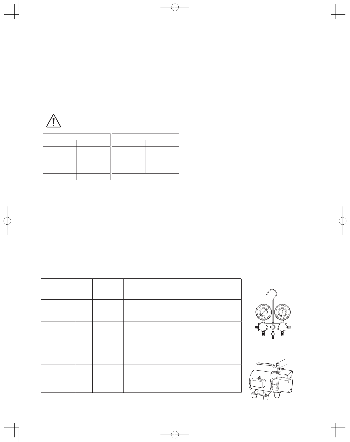
3. Different tools required
3-1. Tool specifications have been changed due to the characteristics of R410A.
Some tools for R22- and R407C-type refrigerant systems cannot be used.
R407C tools
Item
Manifold gauge Yes No
Charge hose Yes No To resist higher pressure, material must be changed.
Vacuum pump Yes Yes
Leak detector Yes No
Flaring oil Yes No
* Using tools for R22 and R407C and new tools for R410A together can cause defects.
New
tools?
compatible
with R410A?
Remarks
Types of refrigerant, refrigerating machine oil, and
pressure gauge are different.
Use a conventional vacuum pump if it is equipped with
a check valve. If it has no check valve, purchase and
attach a vacuum pump adapter.
Leak detectors for CFC and HCFC that react to chlorine
do not function because R410A contains no chlorine.
Leak detector for HFC134a can be used for R410A.
For systems that use R22, apply mineral oil (Suniso
oil) to the flare nuts on the tubing to prevent refrigerant
leakage. For machines that use R407C or R410A, apply
synthetic oil (ether oil) to the flare nuts.
Manifold gauge
Vacuum pump
Outlet
Inlet
4
00_302411_EN.indd 4 2018/7/4 13:27:15
3-2. Use R410A exclusive cylinder only.
New refrigerant R410A cannot be used for
earlier models
1. Compressor specifications are different.
If recharging a R22 or R407C compressor with
R410A, durability will significantly decrease since
some of the materials used for compressor parts are
different.
Valve
Single-outlet valve
(with siphon tube)
Liquid refrigerant should be recharged
with the cylinder standing on end as
shown.
Liquid
2. Existing tubing cannot be used (especially R22).
Completely cleaning out residual refrigerating
machine oil is impossible, even by flushing.
3. Refrigerating machine oil differs (R22).
Since R22 refrigerating machine oil is mineral oil, it
does not dissolve in R410A. Therefore, refrigerating
machine oil discharged from the compressor can
cause compressor damage.
R22 refrigerating machine oil Mineral oil (Suniso oil)
R407C refrigerating machine oil Synthetic fluid (ether oil)
R410A refrigerating machine oil Synthetic fluid (ether oil)
5
00_302411_EN.indd 5 2018/7/4 13:27:15
CONTENTS
Page Page
IMPORTANT! . . . . . . . . . . . . . . . . . . . . . . . . . . . . . 2
Please Read Before Starting
Check of Density Limit
Precautions for Installation Using New Refrigerant
New refrigerant R410A cannot be used for earlier models
1. GENERAL . . . . . . . . . . . . . . . . . . . . . . . . . . . . . 7
1-1. Tools Required for Installation (not supplied)
1-2. Accessories Supplied
1-3. Type of Copper Tube and Insulation Material
1-4. Additional Materials Required for Installation
1-5. Tubing Length
1-6. Tubing Size
1-7. Straight Equivalent Length of Joints
1-8. Additional Refrigerant Charge
1-9. System Limitations
1-10. Check of Limit Density
1-11. Installing Distribution Joint
1-12. Optional Distribution Joint Kits
1-13. Example of Tubing Size Selection and
Refrigerant Charge Amount
2. SELECTING THE INSTALLATION SITE . . . . . 17
5. HOW TO PROCESS TUBING . . . . . . . . . . . . . 34
5-1. Connecting the Refrigerant Tubing
5-2. Connecting Tubing Between Indoor and
Outdoor Units
5-3. Insulating the Refrigerant Tubing
5-4. Taping the Tubes
5-5. Finishing the Installation
6. AIR PURGING . . . . . . . . . . . . . . . . . . . . . . . . . 37
Air Purging with a Vacuum Pump (for Test Run)
n
Preparation
7. TEST RUN . . . . . . . . . . . . . . . . . . . . . . . . . . . . 40
7-1. Preparing for Test Run
7-2. Test Run Procedure
7-3. Main Outdoor Unit PCB Setting
7-4. Function Switches on P.C. Board
7-5. Auto Address Setting
7-6. Setting Test Run Remote Controller
7-7. Caution for Pump Down
7-8. Self-Diagnosis Function Table and Contents of
Alarm Display
2-1. Outdoor Unit
2-2. Shield for Horizontal Exhaust Discharge
2-3. Installing the Outdoor Unit in Heavy Snow
Areas
2-4. Precautions When Installing in Heavy Snow
Areas
2-5. Dimensions of Wind Ducting
2-6. Dimensions of Snow Ducting
3. HOW TO INSTALL THE OUTDOOR UNIT . . . . 23
3-1. Transporting
3-2. Installing the Outdoor Unit
3-3. Routing the Tubing
3-4. Prepare the Tubing
3-5. Connect the Tubing
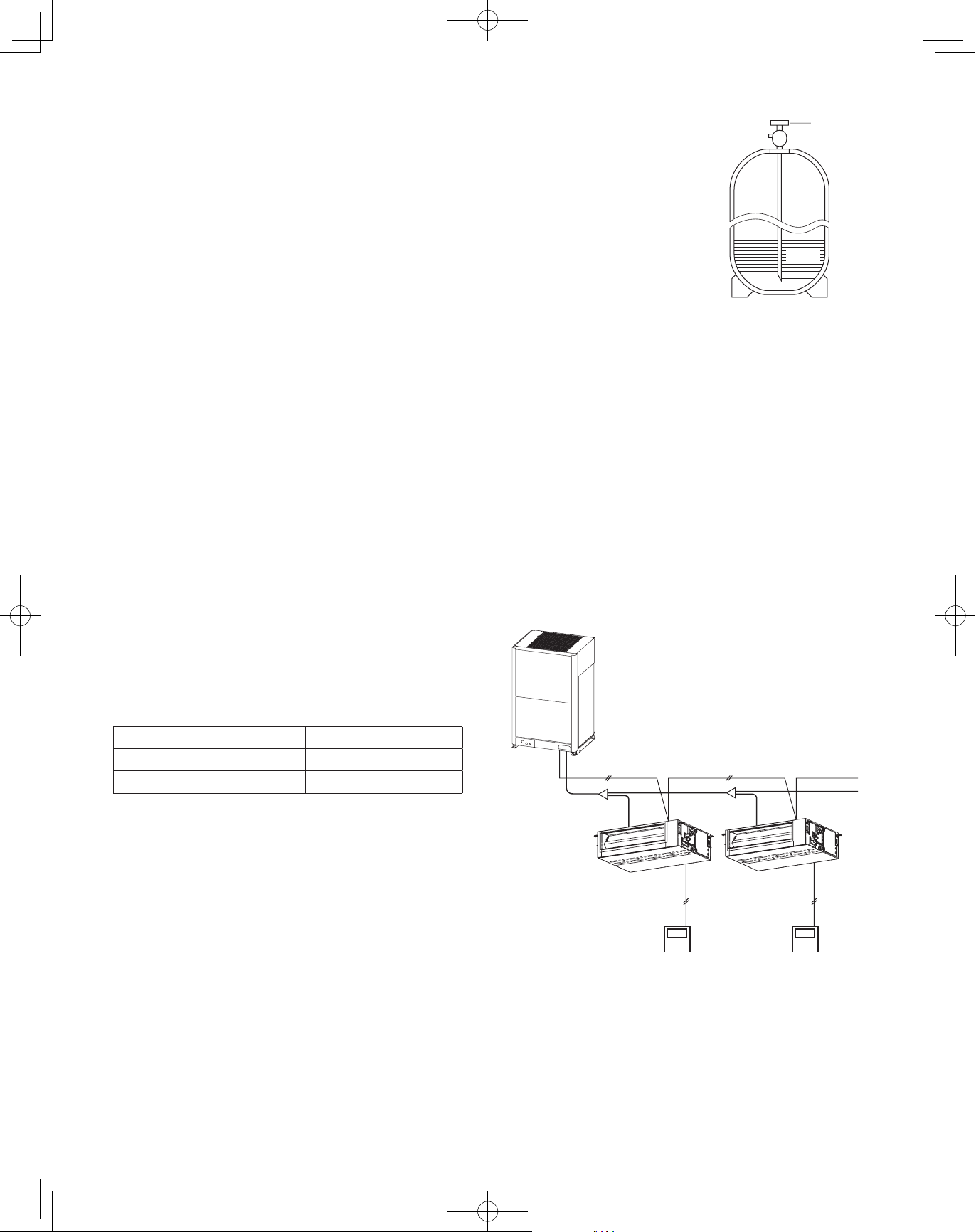
4. ELECTRICAL WIRING . . . . . . . . . . . . . . . . . . 28
4-1. General Precautions on Wiring
4-2. Recommended Wire Length and Wire
Diameter for Power Supply System
4-3. Wiring System Diagram
6
00_302411_EN.indd 6 2018/7/4 13:27:15
CAUTION
1. GENERAL
This booklet briefly outlines where and how to install the air conditioning system. Please read over the entire set of instructions for
the outdoor unit and make sure all accessory parts listed are with the system before beginning.
1-1. Tools Required for Installation (not supplied)
1. Flathead screwdriver
2. Phillips head screwdriver
3. Knife or wire stripper
4. Tape measure
5. Level gauge
6. Sabre saw or keyhole saw
7. Hacksaw
8. Core bits
9. Hammer
10. Drill
11. Tube cutter
12. Tube flaring tool
13. Torque wrench
14. Adjustable wrench
15. Reamer (for deburring)
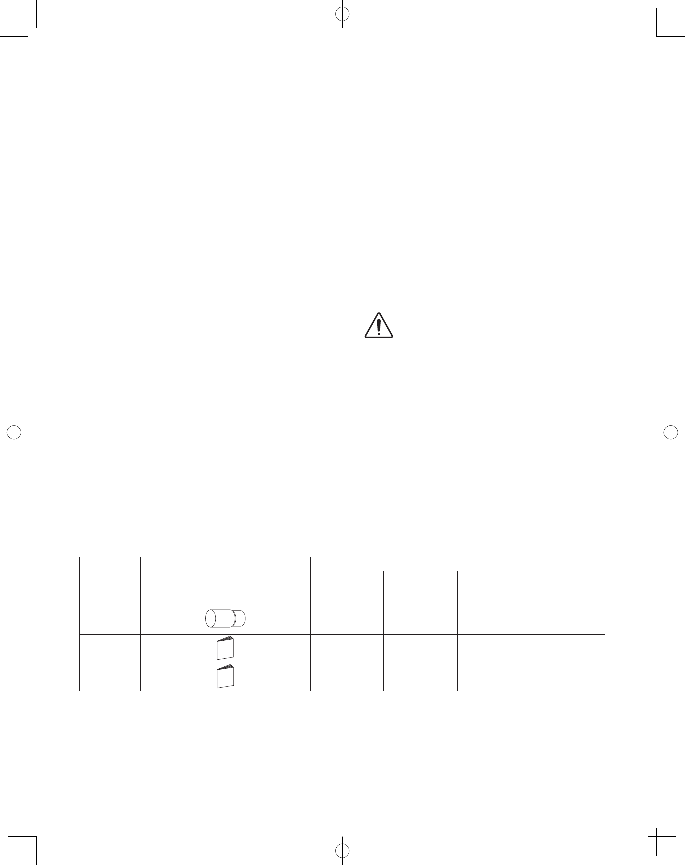
1-2. Accessories Supplied
See Table 1.
1-3. Type of Copper Tube and Insulation Material
If you wish to purchase these materials separately from a local
source, you will need:
1. Deoxidized annealed copper tube for refrigerant tubing.
2. Foamed polyethylene insulation for copper tubes as
required to precise length of tubing. Wall thickness of the
insulation should be not less than 5/16" (7.94mm).
3. Use insulated copper wire for field wiring. Wire size varies
with the total length of wiring.
“
See the section
4. ELECTRICAL WIRING” for details.
Check local electrical codes and
CAUTION
regulations before obtaining
wire. Also, check any specified
instructions or limitations.
1-4. Additional Materials Required for Installation
1. Refrigeration (armored) tape
2. Insulated staples or clamps for connecting wire
(See your local codes.)
3. Putty
4. Refrigeration tubing lubricant
5. Clamps or saddles to secure refrigerant tubing
6. Scale for weighing
Table 1 Outdoor Unit
Part name Figure
Connection
tubing
Operating
Instructions
Installation
Instructions
Outer
diameter
ø1-1/8"(ø28.58)
Inner
diameter
ø1"(ø25.4)
paper
paper
Q’ty
U-72ME2U9
U-72ME2U94
(6 ton)
U-96ME2U9
U-96ME2U94
(8 ton)
U-120ME2U9
U-120ME2U94
(10 ton)
0 0 1 1
1 1 1 1
1 1 1 1
7
U-144ME2U9
U-144ME2U94
(12 ton)
00_302411_EN.indd 7 2018/7/4 13:27:16
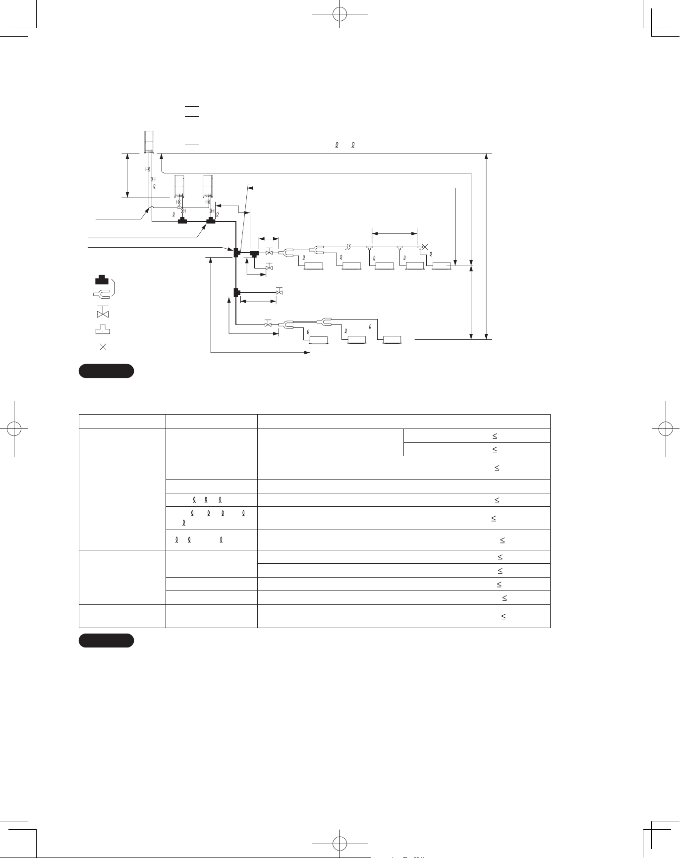
1-5. Tubing Length
Select the installation location so that the length and size of refrigerant tubing are within the allowable range show in the figure below.
1.
Main tubing length (maximum tubing size) LM = LA + LB …
2. Main distribution tubes LC – LH are selected according to the capacity after the distribution joint.
3. The outdoor connection main tubing (LO portion) is determined by the total capacity of the outdoor units that are
connected to the tube ends.
4.
Sizes of indoor unit connection tubing
1 – 64 are determined by the connection tubing sizes on the indoor units.
H3
C
Balance tubing
(ø1/4" (6.35mm))
No.1 distribution joint for outdoor unit
No.1 distribution joint (for indoor unit)
Explanation of symbols
Distribution joint
(CZ: optional parts)
Ball valve (field supply)
T-joint (field supply)
Solidly welded shut
(pinch weld)
LO
LM
AB
LA
LB
LF
Max.1.3 ft (40cm)
Max.1.3 ft (40cm)
LG
L4
LC
For
extension
LD
For
extension
LH
4
1
L1
L2
3L
5
62
3
2
64
63
H2
R410A optional distribution joint
CZ-P680PJ1U (for outdoor unit)
CZ-P1350PJ1U (for outdoor unit)
CZ-P160BK1U (for indoor unit)
CZ-P680BK1U (for indoor unit)
CZ-P1350BK1U (for indoor unit)
H1
NOTE
* Be sure to use special R410A distribution joints (CZ: optional parts) for outdoor unit connections and tubing branches.
Table 1-2 Ranges that Apply to Refrigerant Tubing Lengths and to Differences in Installation Heights
Item Mark Contents Length
Actual length
Equivalent length
Allowable tubing
length
Allowable elevation
difference
Allowable length of
joint tubing
L1 Max. tubing length
L (L2 – L4)
Difference between max. length and min.
length from the No.1 distribution joint
LM Max. length of main tubing (at maximum size)
1, 2~ 64 Max. length of each distribution tube
L1 + 1 + 2~ 63 + A
+ B + LF + LG + LH
A, B + LO, C + LO
H1
Total max. tubing length including length of each distribution
tube (only liquid tubing)
Maximum tubing length from outdoor’s 1st distribution
joint to each outdoor unit
When outdoor unit is installed higher than indoor unit
When outdoor unit is installed lower than indoor unit
H2 Max. difference between indoor units
H3 Max. difference between outdoor units
L3
T-joint tubing (field-supply); Max. tubing length between the
first T-joint and solidly welded-shut end point
unit: ft. (m)
656 (200)*
689 (210)*
164 (50)*
-
164 (50)*
3280 (1000)
33 (10)
164 (50)
131 (40)
49 (15)*
13 (4)
6.6 (2)
4
3
*
6
5
2
2
L = Length
H = Height
NOTE
1: The outdoor connection main tubing (LO portion) is determined by the total capacity of the outdoor units that are connected to
the tube ends.
2: If the longest tubing length (L1) exceeds 295 ft. (90m) (equivalent length), increase the sizes of the main tubes (LM) by 1 rank for
gas tubes and liquid tubes. (Use a field supply reducer.) (Select the tube size from the table of main tube sizes (Table 1-3) on the
following page (LA table), and from the table of refrigerant tubing sizes (Table 1-9) on the second following page.)
3: If the longest main tubing length (LM) exceeds 164 ft. (50m), increase the main tube size at the portion before 164 ft. (50m) by 1
rank for the gas tubes. (Use a field supply reducer.)
(For the portion that exceeds 164 ft. (50m), set based on the main tube sizes (LA) listed in the table on the following page.)
4: If the tubing length marked "L" (L2 - L4) exceeds 131 ft. (40m), increase the liquid tube and gas tube by 1 rank.
5: If the total distribution tubing length exceeds 1,640ft. (500m), maximum allowable elevation difference (H2) between the indoor
units is calculated by the following formula. Make sure the indoor unit’s actual elevation difference should fall within the figure
calculated as follows.
Unit of account (feet): 49 x (2 - total tubing length(ft.) ÷ 1,640) or Unit of account (meter): 15 x (2 - total tubing length(m) ÷ 500)
6: If any of the tubing length exceeds 98ft. (30m), increase the size of the liquid and gas tubes by 1 rank.
8
00_302411_EN.indd 8 2018/7/4 13:27:16

1-6. Tubing Size
Table 1-3 Main Tubing Size (LA)
Between No.1 distribution joint for outdoor unit and No.1 distribution joint (for indoor unit)
BTU/h
(kW)
Total system
tonnage
Gas tubing
Liquid tubing
72,000
(21.1)
ø3/4"
(ø19.05)
96,000
(28.1)
6 8 10 12 14 16 18 20 22 24 26 28 30
ø7/8"
(ø22.22)
ø3/8"
(ø9.52)
120,000
(35.2)
(ø12.7)
ø1/2"
144,000
(42.2)
168,000
(49.2)
ø1-1/8"
(ø28.58)
192,000
(56.3)
ø5/8"
(ø15.88)
216,000
(63.3)
240,000
(70.3)
264,000
(77.4)
288,000
(84.4)
ø1-3/8"
(ø34.92)
(ø19.05)
312,000
(91.4)
ø3/4"
*1: If future extension is planned, select the tubing diameter based on the total tonnage after extension.
However, extension is not possible if the resulting tubing size is three ranks higher.
*2: The balance tube (outdoor unit tube) diameter is ø1/4" (6.35mm).
*3: Type 1 tubing should be used for the refrigerant tubes.
Size of tubing (LO) between outdoor units
n
Select the size of tubing between outdoor units based on the main tubing size (LA) as given in the table above.
Table 1-4 Main Tubing Size After Distribution (LB, LC...)
Total capacity
after distribution
Tubing size
Below BTU/h (kW)
Over BTU/h (kW) –
Gas tubing
Liquid tubing
24,200
(7.09)
ø1/2"
(ø12.7)
ø3/8"
(ø9.52)
54,600
(16.0)
24,200
(7.09)
ø5/8"
(ø15.88)
ø3/8"
(ø9.52)
76,800
(22.5)
54,600
(16.0)
ø3/4"
(ø19.05)
ø3/8"
(ø9.52)
102,400
(30.0)
76,800
(22.5)
ø7/8"
(ø22.22)
ø3/8"
(ø9.52)
143,300
(42.0)
102,400
(30.0)
ø1-1/8"
(ø28.58)
ø1/2"
(ø12.7)
178,800
(52.4)
143,300
(42.0)
ø1-1/8"
(ø28.58)
ø1/2"
(ø12.7)
238,900
(70.0)
178,800
(52.4)
ø1-1/8"
(ø28.58)
ø5/8"
(ø15.88)
340,000
(99.6)
238,900
(70.0)
ø1-3/8"
(ø34.92)
ø3/4"
(ø19.05)
Note: In case the total capacity of connected indoor units exceeds the total capacity of the outdoor units, select the main tubing size
for the total capacity of the outdoor units.
Unit: in. (mm)
336,000
(98.4)
Unit: in. (mm)
–
340,000
(99.6)
ø1-5/8"
(ø41.28)
ø3/4"
(ø19.05)
360,000
(105.5)
ø1-5/8"
(ø41.28)
A
Table 1-5 Outdoor Unit Tubing Connection Size (
BTU/h
(kW)
Gas tubing
Liquid tubing
Balance tubing
72,000
(21.1)
ø3/4"
(ø19.05)
ø3/8" (ø9.52) ø3/8" (ø9.52) ø1/2" (ø12.7)
96,000
(28.1)
ø7/8"
(ø22.22)
Brazing connection
Flare connection
ø1/4" (ø6.35)
Flare connection
120,000
(35.2)
–
ø1-1/8"
(ø28.58)
C
)
Unit: in. (mm)
144,000
(42.2)
ex.) type72
Balance
tube
Liquid tube
Table 1-6 Refrigerant Charge Amount at Shipment (for outdoor unit)
BTU/h (kW) 72,000 (21.1) 96,000 (28.1) 120,000 (35.2) 144,000 (42.2)
Initial amount
Table 1-7 Indoor Unit Tubing Connection Size
oz (g) 321 (9,100) 363 (10,300) 300 (8,500) 416 (11,800)
Unit: in. (mm)
Indoor unit type 7 9 12 15 18 24 36 48 54
Gas tubing ø1/2" (ø12.7) ø5/8" (ø15.88)
Liquid tubing ø1/4" (ø6.35) ø3/8" (ø9.52)
Gas tube
9
00_302411_EN.indd 9 2018/7/4 13:27:17
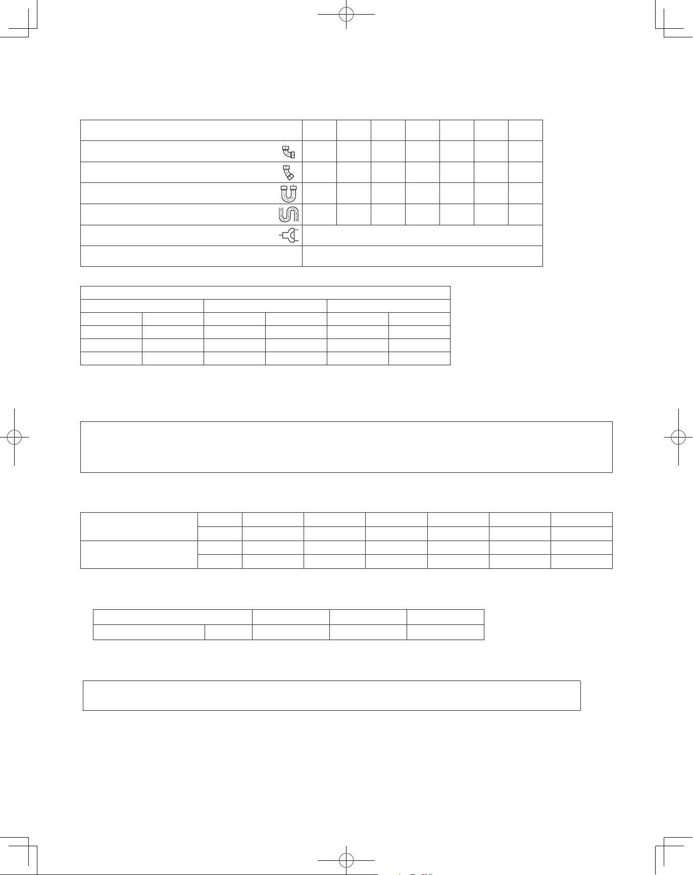
1-7. Straight Equivalent Length of Joints
Design the tubing system by referring to the following table for the straight equivalent length of joints.
Table 1-8 Straight Equivalent Length of Joints
Gas tubing size (in. (mm))
90° elbow
45° elbow
U-shape tube bent (R2-3/8" – 4" (60 – 100mm))
Trap bend
Y-branch distribution joint
Ball valve for service Equivalent length conversion not needed.
1/2"
(12.7)
(0.30)
0.8
(0.23)
(0.90)
7.5
(2.30)
Table 1-9 Refrigerant tubing (Existing tubing can be used.)
Tubing size (in. (mm))
Material: O Material: O Material: O
Outer diameter Wall thickness Outer diameter Wall thickness Outer diameter Wall thickness
1/4" (6.35) 0.025 (0.635) 5/8" (15.88) 0.040 (1.016) 1-1/8" (28.58) 0.050 (1.27)
3/8" (9.52) 0.030 (0.762) 3/4" (19.05) 0.042 (1.0668) 1-3/8" (34.92) 0.055 (1.397)
1/2" (12.7) 0.035 (0.889) 7/8" (22.22) 0.045 (1.143) 1-5/8" (41.28) 0.060 (1.524)
1
3
5/8"
(15.88)
1.1
(0.35)
0.9
(0.26)1(0.32)
3.4
(1.05)
9.2
(2.80)
Equivalent length conversion not needed.
3/4"
(19.05)
1.4
(0.42)
4.1
(1.26)
10.5
(3.20)
7/8"
(22.22)
1.6
(0.48)
1.2
(0.36)
4.7
(1.44)
12.5
(3.80)
1-1/8"
(28.58)
1.9
(0.57)
1.4
(0.43)
5.6
(1.71)
15.4
(4.70)
* When bending the tubes, use a
bending radius that is at least 4 times
the outer diameter of the tubes.
In addition, take sufficient care to
avoid crushing or damaging the tubes
when bending them.
1-3/8"
(34.92)
2.5
(0.76)
1.8
(0.55)
7.4
(2.26)
19.2
(5.85)
Unit: ft. (m)
1-5/8"
(41.28)
2.8
(0.85)
2.0
(0.61)
8.4
(2.56)
22.3
(6.80)
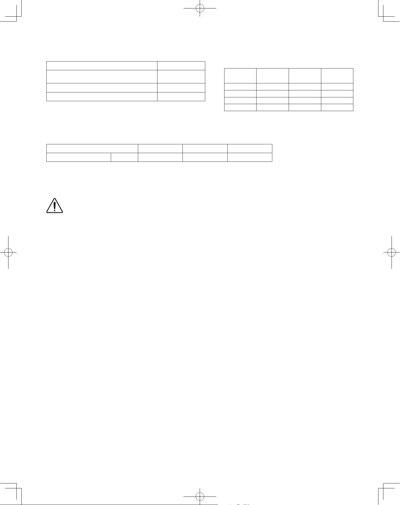
1-8. Additional Refrigerant Charge
Additional refrigerant charge amount is calculated from the liquid tubing total length, combination number of outdoor unit and
refrigerant amount according to all indoor unit cooling capacity.
Required amount of additional refrigerant charge
= [(Necessary amount of additional refrigerant charge per ft. (m) of each size of liquid tube x its tube length) + (...) + (...)]
+ [Necessary amount of additional refrigerant charge per outdoor unit]
+ [Necessary amount of additional refrigerant charge for all indoor unit cooling capacity]
* Always charge accurately using a scale for weighing.
Table 1-10-1 Necessary Amount of Additional Refrigerant Charge Per ft. (or per meter), According to Liquid Tubing Size
Liquid tubing size
Additional amount
Table 1-10-2 Necessary Amount of Additional Refrigerant Charge Per Outdoor Unit
Further charge a certain amount listed below in addition to the amount of refrigerant charge.
Combination number of outdoor unit 1 2 3
Additional amount oz (g) 70.5 (2,000) 141.0 (4,000) 212 (6,000)
Necessary Amount of Additional Refrigerant Charge for All Indoor Unit Cooling Capacity
Charge a refrigerant amount calculated in the following formula according to the total amount of indoor unit cooling capacity.
inch ø1/4" ø3/8" ø1/2" ø5/8" ø3/4" ø7/8"
(mm) (ø6.35) (ø9.52) (ø12.7) (ø15.88) (ø19.05) (ø22.22)
oz/ft. 0.279 0.602 1.38 1.99 2.78 3.93
(g/m) (26) (56) (128) (185) (259) (366)
Additional refrigerant amount when cooling capacity is BTU/h = Cooling capacity (BTU/h) x 1.034 x 0.001 + 10.6 (oz)
or Additional refrigerant amount when cooling capacity is kW = Cooling capacity (kW) x 1000 x 0.1 + 300 (g)
10
00_302411_EN.indd 10 2018/7/4 13:27:17
1-9. System Limitations
CAUTION
Table 1-11 System Limitations
Max. No. allowable connected outdoor units 3
Max. capacity allowable connected outdoor
units
360,000 BTU/h
(30 ton, 105.5 kW)
Max. connectable indoor units 64
Max. allowable indoor/outdoor capacity ratio 50 – 200 %
*2
*1
*3
*1: In the case of 18 ton (63.3kW) or smaller units, the number is
limited by the total capacity of the connected indoor units.
*2: Up to 3 units can be connected if the system has been extended.
*3: It is strongly recommended that you choose the unit so the load
can become between 50 and 130%.
Table 1-12 System Limitations of Total Refrigerant Amount
Combination number of outdoor unit 1 2 3
g
Upper limit oz (
) 1,763 (50,000) 2,821 (80,000) 3,703 (105,000)
Make sure the values calculated using the following formula should not exceed the maximum allowable values (Table 1-12).
Total refrigerant amount = Refrigerant charge amount at shipment (for outdoor unit)
+ Necessary amount of additional refrigerant charge per ft. (or per meter) according to liquid tubing size
+ Necessary amount of additional refrigerant charge per outdoor unit
+ Necessary amount of additional refrigerant charge for all indoor unit cooling capacity
Maximum number of connectable indoor units
when connected with minimum capacity
Total system
tonnage
Number of
indoor units
Total system
tonnage
Number of
indoor units
6 20 14 45
8 25 16 50
10 32 18 55
12 39 20~30 64
WARNING
Always check the gas density limit for the room in which the unit is installed.
1-10. Check of Limit Density
When installing an air conditioner in a room, it is necessary to ensure that even if the refrigerant gas accidentally leaks out, its
density does not exceed the limit level for that room.
11
00_302411_EN.indd 11 2018/7/4 13:27:17
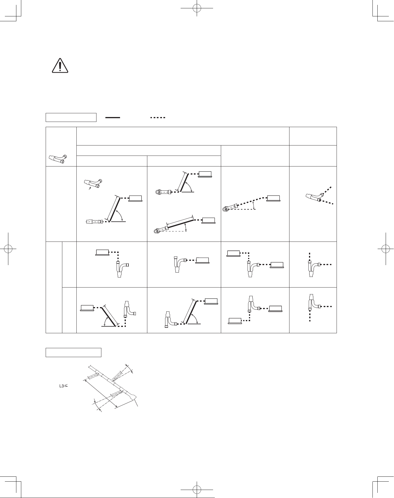
1-11. Installing Distribution Joint
CAUTION
15〜90°
CAUTION
Pay special attention to any location, such as a basement, etc., where leaking refrigerant can
accumulate, since refrigerant gas is heavier than air.
(1) Refer to “HOW TO ATTACH DISTRIBUTION JOINT” enclosed with the optional distribution joint kit (CZ-P680PJ1U,
CZ-P1350PJ1U, CZ-P160BK1U, CZ-P680BK1U, CZ-P1350BK1U).
● When connecting a branch tubing to the indoor unit directly, it is necessary for each branch tubing to install at a positive angle
with respect to horizontal in order to prevent accumulation of refrigerant oil in stopped units. (See the below chart.)
Branch tubing system Restricted
How to install
branch tubing
B
A
Horizontal
* In case of common use solenoid valve kit
When connecting to A When connecting to B
B
A
D
Straight tubing
length over
8 in. (200mm)
Arrow view D
When connecting branch tubing to indoor unit directly
Suction tube
15〜90°
Not restricted
Straight tubing
length over
8 in. (200mm)
Horizontal
Straight tubing length
over 8 in. (200mm)
or
15〜90°
15〜30°
(Branch tubing
angle)
Liquid tube / Discharge tube
0〜30°
(Branch tubing
angle)
When not connecting
branch tubing to indoor
unit directly
Suction tube /
Discharge tube /
Liquid tube
Horizontal
Upward
Vertical
Downward
Header branch system
Outdoor
Indoor
6.5 ft. (2m)
(From 1st branch to tip
of solidly welded part)
Horizontal line
Install at a positive angle
Vertical
Straight tubing
length over
8 in. (200mm)
15〜90°
(Main tubing is horizontal.)
Indoor
Install at a positive angle
Indoor
(15~30°)
Vertical
Straight tubing
length over
Vertical
Horizontal line
Solidly welded shut (X)
8 in. (200mm)
Vertical
(15~30°)
Vertical
Vertical
15〜90°
Vertical
Vertical
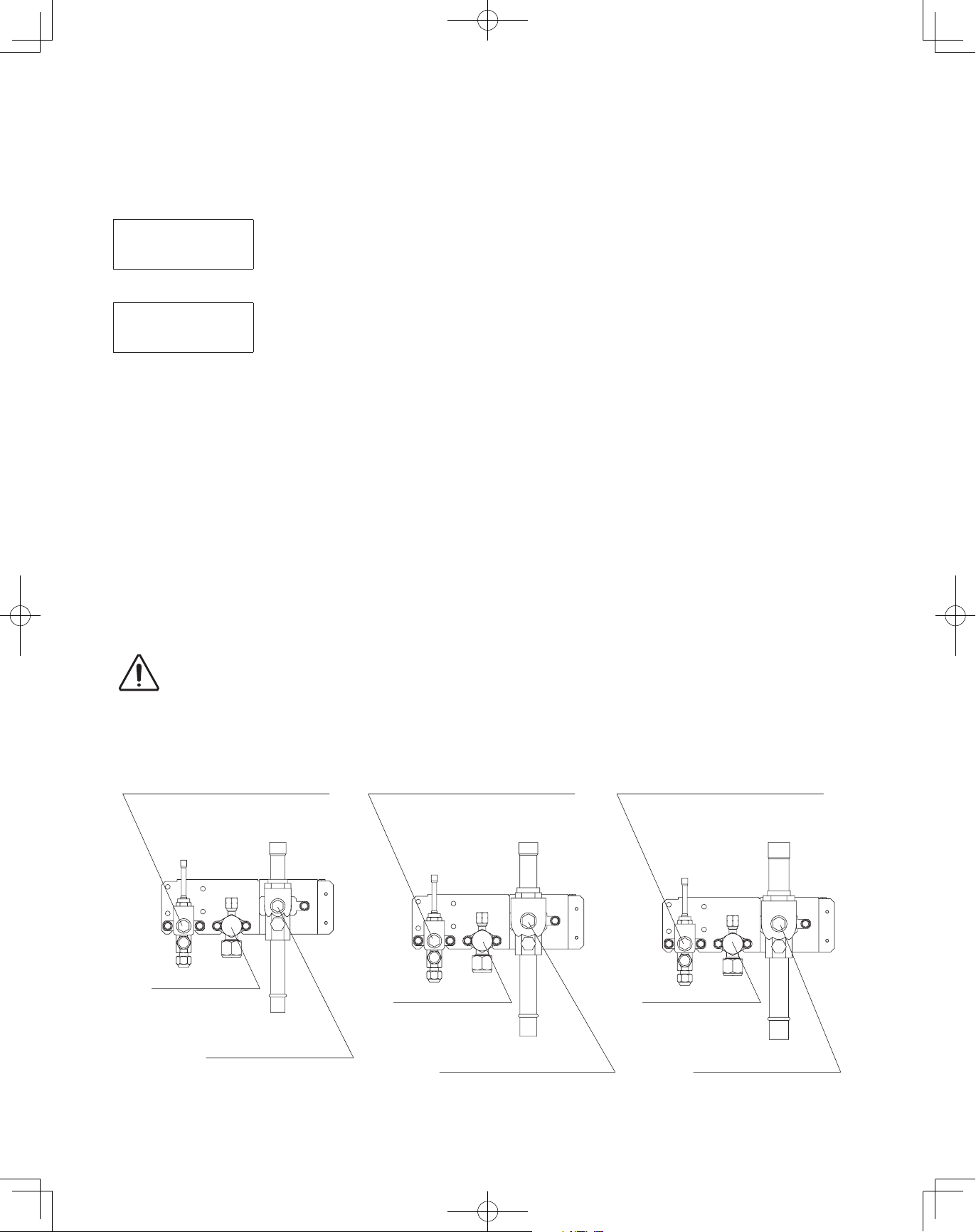
● Be sure to solidly weld shut the T-joint end (marked by X in
the figure). In addition, pay attention to the insertion depth
of each connected tube so that the flow of refrigerant within
the T-joint is not impeded.
Be sure to use a commercial available T-joint.
● When using the header joint system, do not make further
branches in the tubing.
● Do not use the header joint system on the outdoor unit
side.
12
00_302411_EN.indd 12 2018/7/4 13:27:18
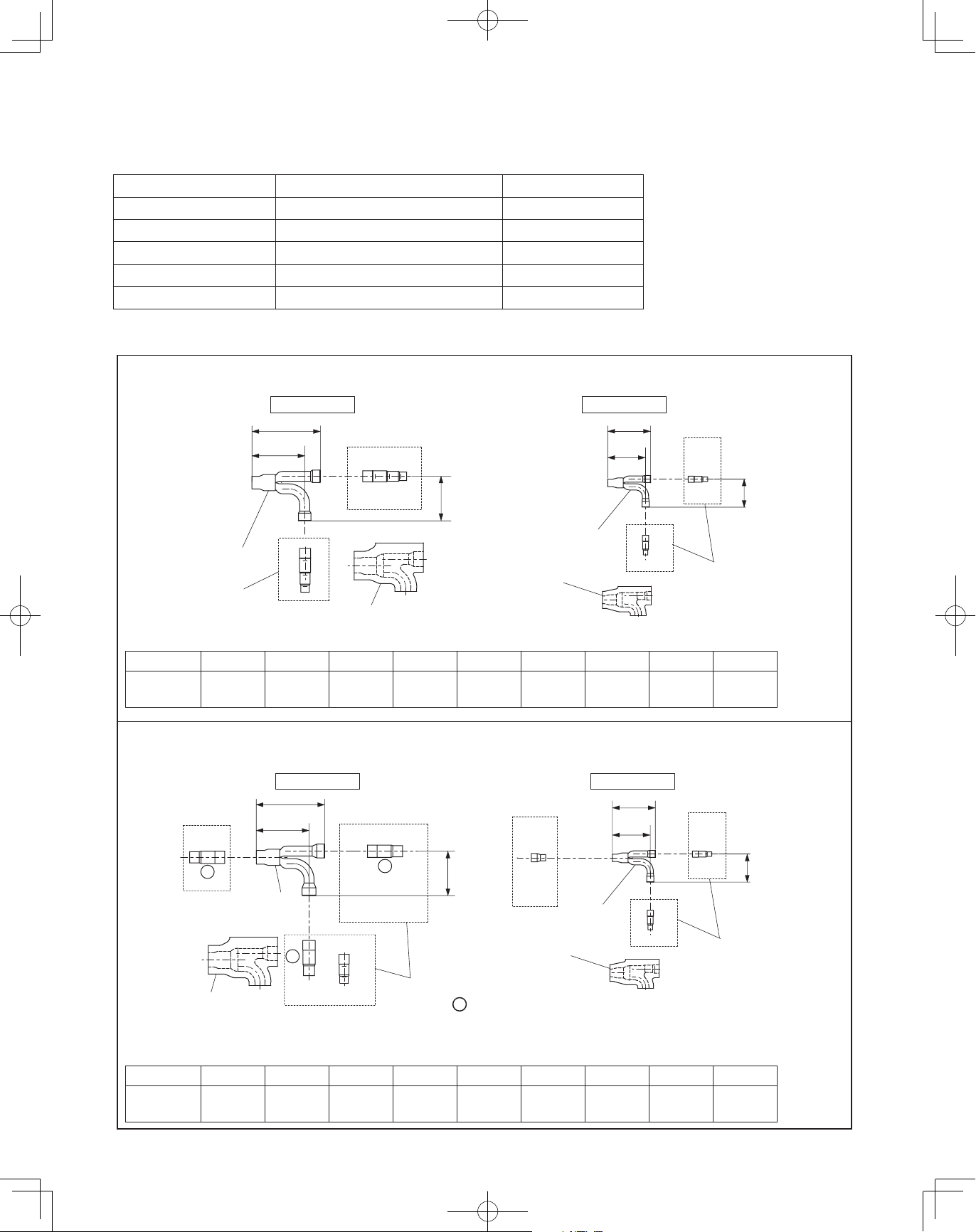
1-12. Optional Distribution Joint Kits
4-21/64
2-53/64
2-53/64
6-57/64
4-21/64
See the installation instructions packaged with the distribution joint kit for the installation procedure.
Table 1-12
Model name Cooling capacity after distribution Remarks
1. CZ-P680PJ1U 232,000 BTU/h (68.0 kW) or less For outdoor unit
2. CZ-P1350PJ1U more than 232,000 BTU/h (68.0 kW) For outdoor unit
3. CZ-P160BK1U 76,400 BTU/h (22.4 kW) or less* For indoor unit
4. CZ-P680BK1U 232,000 BTU/h (68.0 kW) or less* For indoor unit
5. CZ-P1350BK1U more than 232,000 BTU/h (68.0 kW)* For indoor unit
Tubing size (with thermal insulation)
n
1. CZ-P680PJ1U
For outdoor unit (Capacity after distribution joint is 232,000 BTU/h (68.0 kW) or less.)
Example:
Distribution
Joint
Reducing
Joints
Gas tubing Liquid tubing
6-59/64
(175)
5-5/16
(135)
C
C
Insulation
4-31/64
(114)
F E D C
Insulation
G
Distribution
Joint
* In case the total capacity of indoor
(110)
3-13/16
(97)
G
G
H
I
units connected after distribution
exceeds the total capacity of the
outdoor units, select the distribution
tube size for the total capacity of the
outdoor units.
HI
(72)
Reducing
Joints
Unit: in. (mm)
Table 1-13 Size of connection point on each part (Shown are inside diameters of tubing)
Size Part A Part B Part C Part D Part E Part F Part G Part H Part I
in. (mm)
ø1-3/8"
(ø34.92)
ø1-1/4"
(ø31.75)
ø1-1/8"
(ø28.58)
ø1"
(ø25.4)
ø7/8"
(ø22.22)
ø3/4"
(ø19.05)
ø5/8"
(ø15.88)
ø1/2"
(ø12.7)
2. CZ-P1350PJ1U
For outdoor unit (Capacity after distribution joint is greater than 232,000 BTU/h (68.0 kW).)
Example:
C
D
Insulation
With regard to the diameter of the tube without description in Table 1-14, use a reducer (field supply) to adjust the tube diameter.
*
B
A
Distribution
Joint
Gas tubing Liquid tubing
(175)
5-5/16
(135)
B
B
C
A
D
E
F
C
A
Reducing
Joints
D
4-31/64
(114)
: Outside dimension
F
Insulation
G
Distribution
Joint
(110)
3-13/16
(97)
G
H I
G
H
I
Reducing
Joints
Table 1-14 Size of connection point on each part (Shown are inside diameters of tubing)
ø3/4"
ø5/8"
(ø15.88)
ø1/2"
(ø12.7)
Size Part A Part B Part C Part D Part E Part F Part G Part H Part I
in. (mm)
ø1-3/8"
(ø34.92)
ø1-1/4"
(ø31.75)
ø1-1/8"
(ø28.58)
ø1"
(ø25.4)
ø7/8"
(ø22.22)
(ø19.05)
ø3/8"
(ø9.52)
(72)
Unit: in. (mm)
ø3/8"
(ø9.52)
13
00_302411_EN.indd 13 2018/7/4 13:27:18
3. CZ-P160BK1U Use: For indoor unit (Capacity after distribution joint is 76,400 BTU/h (22.4 kW) or less.)*
4-21/64
4-21/64
2-53/64
6-57/64
2-53/64
2-53/64
6-57/64
Example:
A
Insulation
(110)
3-13/16 3-13/16
(97)
B
Distribution
Joint
B
B
C
Gas tubing
C
A
(72)
2-53/64
D
Insulation
(110)
(97)
C
Distribution
Joint
C
C
D
E
Liquid tubing
D E
Unit: in. (mm)
(72)
Table 1-15 Size of connection point on each part (Shown are inside diameters of tubing)
Size Part A Part B Part C Part D Part E
in. (mm)
ø3/4"
(ø19.05)
ø5/8"
(ø15.88)
ø1/2"
(ø12.7)
ø3/8"
(ø9.52)
ø1/4"
(ø6.35)
4. CZ-P680BK1U Use: For indoor unit (Capacity after distribution joint is greater than 76,400 BTU/h (22.4 kW) and no more
than 232,000 BTU/h (68.0 kW).)*
Example:
D C B
Insulation
A
Distribution
Joint
(175)
5-5/16
(135)
A
Gas tubing
4-31/64
A
B
C
D
E
F
B C D
Reducing
Joints
E F
(114)
F G
Distribution
Joint
Insulation
4-21/64
(110)
3-13/16
(97)
E
E
F
G
H
E
Liquid tubing
(72)
F G H
Reducing
Joints
Unit: in. (mm)
Table 1-16 Size of connection point on each part (Shown are inside diameters of tubing)
Size Part A Part B Part C Part D Part E Part F Part G Part H
in. (mm)
ø1-1/8"
(ø28.58)
ø1"
(ø25.4)
ø7/8"
(ø22.22)
ø3/4"
(ø19.05)
ø5/8"
(ø15.88)
ø1/2"
(ø12.7)
ø3/8"
(ø9.52)
ø1/4"
(ø6.35)
5. CZ-P1350BK1U Use: For indoor unit (Capacity after distribution joint is greater than 232,000 BTU/h (68.0 kW).)*
G
ø5/8"
(ø15.88)
4-21/64
(110)
3-13/16
(97)
G
H
I
J
G
ø1/2"
(ø12.7)
Liquid tubing
F
H
Reducing
Joints
Unit: in. (mm)
ø3/8"
(ø9.52)
(72)
Example:
A
C D
Insulation
*
With regard to the diameter of the tube without description in Table 1-17, use a reducer (field supply) to adjust the tube diameter.
Table 1-17 Size of connection point on each part (Shown are inside diameters of tubing)
Size Part A Part B Part C Part D Part E Part F Part G Part H Part I Part J
in. (mm)
ø1-3/8"
(ø34.92)
(175)
5-5/16
(135)
B
Distribution
Joint
C
D
E
F
G
H
ø1-1/4"
(ø31.75)
B
B
A
ø1-1/8"
(ø28.58)
Gas tubing
Reducing
Joints
ø1"
(ø25.4)
C D
A
4-31/64
(114)
: Outside dimension
ø7/8"
(ø22.22)
ø3/4"
(ø19.05)
F
Distribution
Joint
Insulation
In case the total capacity of indoor units connected after distribution exceeds the total capacity of the outdoor units, select the
distribution tube size for the total capacity of the outdoor units.
14
ø1/4"
(ø6.35)
00_302411_EN.indd 14 2018/7/4 13:27:18
1-13. Example of Tubing Size Selection and Refrigerant Charge Amount
CAUTION
Additional refrigerant charging
Based on the values in Tables 1-3, 4, 5, 7, 10-1 and 10-2, use the liquid tubing size and length, and calculate the amount of
additional refrigerant charge using the formula below.
Unit of account (oz)
Required additional
refrigerant charge (oz)
or
g
Unit of account (
)
Required additional
refrigerant charge (g)
(a) : Liquid tubing Total length of ø7/8" (ft.) or (m) (d) : Liquid tubing Total length of ø1/2" (ft.) or (m)
(b) : Liquid tubing Total length of ø3/4" (ft.) or (m) (e) : Liquid tubing Total length of ø3/8" (ft.) or (m)
(c) : Liquid tubing Total length of ø5/8" (ft.) or (m) (f) : Liquid tubing Total length of ø1/4" (ft.) or (m)
Charging procedure
●
Be sure to charge with R410A refrigerant in liquid form.
1. After performing a vacuum, charge with refrigerant from the liquid tubing side.
At this time, all valves must be in the “fully closed” position.
2. If it was not possible to charge the designated amount, operate the system in Cooling mode while charging with refrigerant
from the gas tubing side. (This is performed at the time of the test run. For this, all valves must be in the “fully open” position.
However, if only one outdoor unit is installed, a balance tube is not used. Therefore, leave the valves fully closed.)
Charge with R410A refrigerant in liquid form.
With R410A refrigerant, charge while adjusting the amount being fed a little at a time in order to prevent liquid refrigerant from
backing up.
After charging is completed, turn all valves to the “fully open” position.
●
Replace the tubing covers as they were before.
●
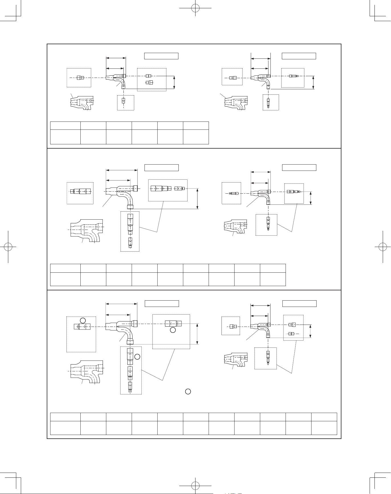
CAUTION
For type 72 For type 96 For type 120/144
Balance tube
Use a flathead screwdriver and
open by turning the part with the
screw groove to the right, from “–”
to “|”.
Necessary Amount of Additional Refrigerant Charge Per Outdoor Unit
=
+ 3.93 × (a) + 2.78 × (b) + 1.99 × (c) + 1.38 × (d) + 0.602 × (e) + 0.279 × (f)
+ Necessary amount of additional refrigerant charge for all indoor unit cooling capacity
Necessary Amount of Additional Refrigerant Charge Per Outdoor Unit
=
+ 366 × (a) + 259 × (b) + 185 × (c) + 128 × (d) + 56 × (e) + 26 × (f)
+ Necessary amount of additional refrigerant charge for all indoor unit cooling capacity
1. R410A additional charging absolutely must be done through liquid charging.
2. The R410A refrigerant cylinder has a gray base color, and the top part is pink.
3. The R410A refrigerant cylinder includes a siphon tube. Check that the siphon tube is present.
(This is indicated on the label at the top of the cylinder.)
4. Due to differences in the refrigerant, pressure, and refrigerant oil involved in installation, it is
not possible in some cases to use the same tools for R22 and for R410A.
Balance tube
Use a flathead screwdriver and
open by turning the part with the
screw groove to the right, from “–”
to “|”.
Balance tube
Use a flathead screwdriver and
open by turning the part with the
screw groove to the right, from “–”
to “|”.
Liquid tube
Use a hex wrench
(width 5/32 inch (4mm))
and turn to the left to
open.
Gas tube
Use a flathead screwdriver and
open by turning the part with the
screw groove to the right, from “–”
to “|”.
Liquid tube
Use a hex wrench
(width 5/32 inch (4mm))
and turn to the left to
open.
Gas tube
Use a flathead screwdriver and
open by turning the part with the
screw groove to the right, from “–”
to “|”.
Liquid tube
Use a hex wrench
(width 5/32 inch (4mm))
and turn to the left to
open.
Gas tube
Use a flathead screwdriver and
open by turning the part with the
screw groove to the right, from “–”
to “|”.
15
00_302411_EN.indd 15 2018/7/4 13:27:19
Example:
Outdoor unit
Type 96 Type 72
B
Example of all outdoor units
●
cooling capacity
Type 72: 72,000 BTU/h (21.1 kW)
Type 96: 96,000 BTU/h (28.1 kW)
[Total]
A
LA
168,000 BTU/h (49.2 kW)
LB
1 2 3 4
LC
Example of each tubing length
●
Main tubing Distribution joint tubing
LA = 131 ft. (40m) Outdoor side Indoor side
LB = 16 ft. (4.9m)
LC = 16 ft. (4.9m)
A = 7 ft.
B = 7 ft.
(2.1m)
(2.1m)
1 = 98 ft.
2 = 16 ft.
3 = 16 ft.
4 = 65 ft.
Example of all indoor unit cooling capacity
●
(30m)
(4.9m)
(4.9m)
(19.8m)
[Type 48 x 3] 47,800 x 3 = 143,400 BTU/h (14.0 x 3 = 42.0 kW)
Type 48 Type 48 Type 48 Type 36
[Type 36 x 1] 36,000 x 1 = 36,000 BTU/h (10.6 x 1 = 10.6 kW)
[Total] 179,400 BTU/h (52.6 kW)
Obtain liquid tubing size from Tables 1-3, 4, 5, 7 and 10-1.
●
Main tubing
LA = ø5/8 (in.) (Total capacity of indoor unit is 179,400 BTU/h (52.6kW))
LB = ø1/2 (in.) (Total capacity of indoor unit is 131,600 BTU/h (38.6kW))
LC = ø3/8 (in.) (Total capacity of indoor unit is 83,800 BTU/h (24.6kW))
Distribution joint tubing
Outdoor side
Indoor side
Obtain additional charge amount for each tubing size and additional refrigerant charge amount for all indoor unit cooling capacity.
●
A: ø3/8 (in.) B: ø3/8 (in.) (from outdoor unit connection tubing)
1: ø3/8 (in.) 2: ø3/8 (in.) 3: ø3/8 (in.) 4: ø3/8 (in.) (from indoor unit connection tubing)
Note 1: The charge amounts per 1 ft. are different for each liquid tubing size.
ø5/8 (in.)
ø1/2 (in.)
ø3/8 (in.)
LA : 131 ft. × 1.99 oz/ft. = 261 oz (40m × 185 g/m = 7,400g)
→
LB : 16 ft. × 1.38 oz/ft. = 22 oz (4.9m × 128 g/m = 627g)
→
→
LC +
A – B + 1 – 4
: 225 ft. × 0.602 oz/ft. = 135 oz (68.6m × 56 g/m = 3,842g)
Total 418 oz (Total 11,869g)
Additional refrigerant charge amount is 418 oz (11,869g).
Note 2: Necessary amount of additional refrigerant charge per outdoor unit is 141oz (4,000g) in combination of 2 units.
(See the Table 1-10-2.)
Note 2) Amount of additional charge for outdoor unit (combination number) : 141oz (4,000g)
Note 3: Necessary amount of additional refrigerant charge for all indoor unit cooling capacity
[BTU/h] [kW]
179,400 BTU/h
Cooling capacity (BTU/h) x 1.034 x 0.001 + 10.6 oz
= 179,400 x 1.034 x 0.001 + 10.6 = 196 oz
(52.6 kW)
(Cooling capacity (kW) x1000 x 0.1 + 300
= 52.6 x 1000 x 0.1 + 300 = 5,560 g)
g
Note 1) Amount of additional charge per tubing length : 418 oz (11,869g)
Note 2) Amount of additional charge for outdoor unit (combination number) : 141 oz (4,000g)
Note 3) Amount of additional charge for all indoor unit cooling capacity : 196 oz (5,560g)
Total of additional refrigerant charge amount : 755 oz (21,429g)
Therefore, the total of additional refrigerant charge amount reaches 755 oz (21,429g).
Obtain overall refrigerant charge amount.
●
Overall refrigerant charge amount of the system indicates the calculated value shown above the additional charge amount in
addition to the total refrigerant charge amount (shown in the Table 1-6) at shipment in total cooling capacity of outdoor unit.
Refrigerant charge amount at shipment
(total cooling capacity of outdoor unit) : : [168,000BTU/h] 684 oz [49.2kW] (19,400g)
Total of additional refrigerant charge amount
:
755 oz (21,429g)
Grand total 1,439 oz (40,829g)
Therefore, overall refrigerant charge amount of the system reaches 1,439 oz (40,829g).
Remark:
Be sure to include the values in Table 1-10-2 Necessary Amount of Additional Refrigerant Charge Per Outdoor Unit.
CAUTION
Be sure to check the limit density for the room in which the indoor unit is installed.
16
00_302411_EN.indd 16 2018/7/4 13:27:19
2. SELECTING THE INSTALLATION SITE
CAUTION
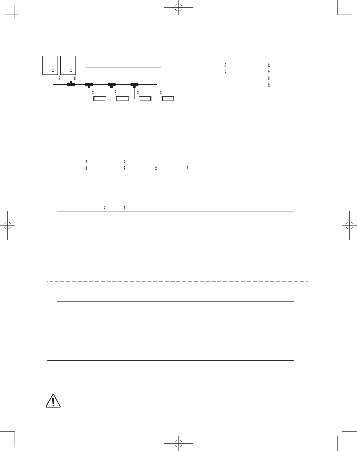
2-1. Outdoor Unit
AVOID:
heat sources, exhaust fans, etc.
●
damp, humid or uneven locations
●
indoors (no-ventilation location)
●
DO:
choose a place as cool as possible.
●
choose a place that is well ventilated.
●
allow enough room around the unit for air intake/exhaust
●
and possible maintenance.
use lug bolts or equal to bolt down unit, reducing vibration
●
and noise.
Exhaust fan
Hot air
Heat
Out-
door
unit
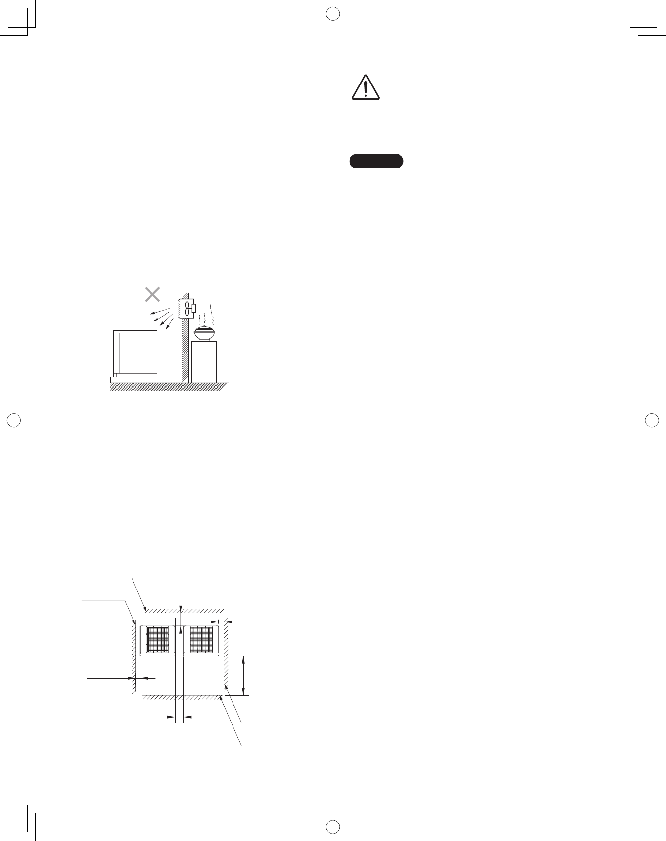
Installation Space
Install the outdoor unit where there is enough space for
ventilation. Otherwise the unit may not operate properly.
The figure shows the minimum space requirement around
the outdoor units when 3 sides are open and only 1 side is
shuttered, with open space above the unit. The mounting
base should be concrete or a similar material that allows for
adequate drainage. Make provisions for anchor bolts, platform
height, and other site-specific installation requirements.
source
Leave space open above the
CAUTION
●
unit.
Construct louvers or other
●
openings in the wall, if
necessary, to ensure adequate
ventilation.
NOTE
Do not do any wiring or tubing within 1 ft. (300mm) of the
●
front panel, because this space is needed as a servicing
space for the compressor.
Ensure a base height of 4 in. (100mm) or more to ensure
●
that drainage water does not accumulate and freeze
around the bottom of the unit.
If installing a drain pan, install the drain pan prior to
●
installing the outdoor unit.
* Make sure there is at least 6 in. (150mm) between the
outdoor unit and the ground.
Also, the direction of the tubing and electrical wiring should
be from the front of the outdoor unit.
* When setting the anchor bolt to "B" or "C" (see page 20),
make enough space for installation operation.
(Space between units: Over 0.6 ft. (180mm), Space from
wall: Over 0.83 ft. (250mm))
* When installing a snow-proof ducting, make space between
the units 7-3/32 in. (180mm) regardless of the positions (A C) for installation holes.
* Make a walk-in space in front and behind the unit to ensure
ease of operation.
Example: 2 units installation
* For other installation, follow the standards of combination
installation.
Wall height: Less than 1.7ft. (500mm)
Wall height:
Unlimited
* Over 2 in.
(50mm)
Over 2-3/8 in. (60mm)
Wall height: Less than 4.9 ft. (1500mm)
Over 1 ft.(300mm)
* Over 2 in. (50mm)
Over 1.7ft. (500mm)
Wall height: Unlimited
17
00_302411_EN.indd 17 2018/7/4 13:27:19
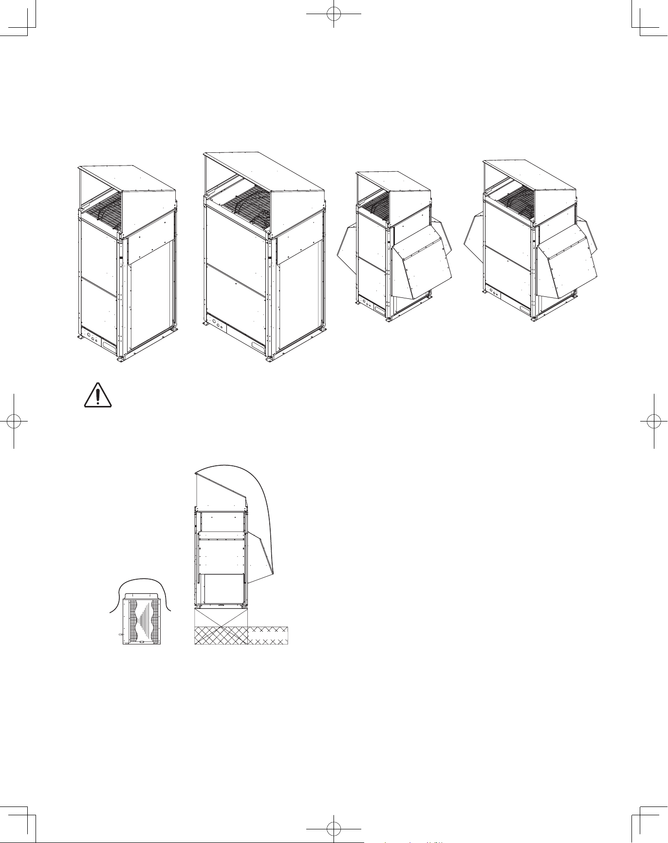
2-2. Shield for Horizontal Exhaust Discharge
CAUTION
It is necessary to install an air-discharge chamber (field
supply) to direct exhaust from the fan horizontally if it is difficult
to provide a minimum space of 7 ft. (2m) between the airdischarge outlet and a nearby obstacle.
In regions with heavy snowfall,
CAUTION
the outdoor unit should be
provided with a solid, raised
platform and snow-proof
ducting (field supply).
DO
2-3. Installing the Outdoor Unit in Heavy Snow
Areas
In locations where wind-blown snow can be a problem,
snow-proof ducting (field supply) should be fitted to the unit
and direct exposure to the wind should be avoided as much as
possible.
The following problems may occur if proper countermeasures
are not taken:
The fan in the outdoor unit may stop running, causing the
●
unit to be damaged.
There may be no air flow.
●
The tubing may freeze and burst.
●
The condenser pressure may drop because of strong wind,
●
and the indoor unit may freeze.
AVOID
Without snowproof ducting
(Without platform)
2-4. Precautions When Installing in Heavy Snow
Areas
a) The platform should be higher than the maximum snow
depth.
b) The 2 anchoring feet of the outdoor unit should be used for
the platform, and the platform should be installed beneath
the air-intake side of the outdoor unit.
c) The platform foundation must be solid and the unit must be
secured with anchor bolts.
d) When installing on a roof subject to strong wind,
countermeasures must be taken to prevent the unit from
being overturned.
Fallen snow
With snowproof ducting
(High platform)
18
00_302411_EN.indd 18 2018/7/4 13:27:22
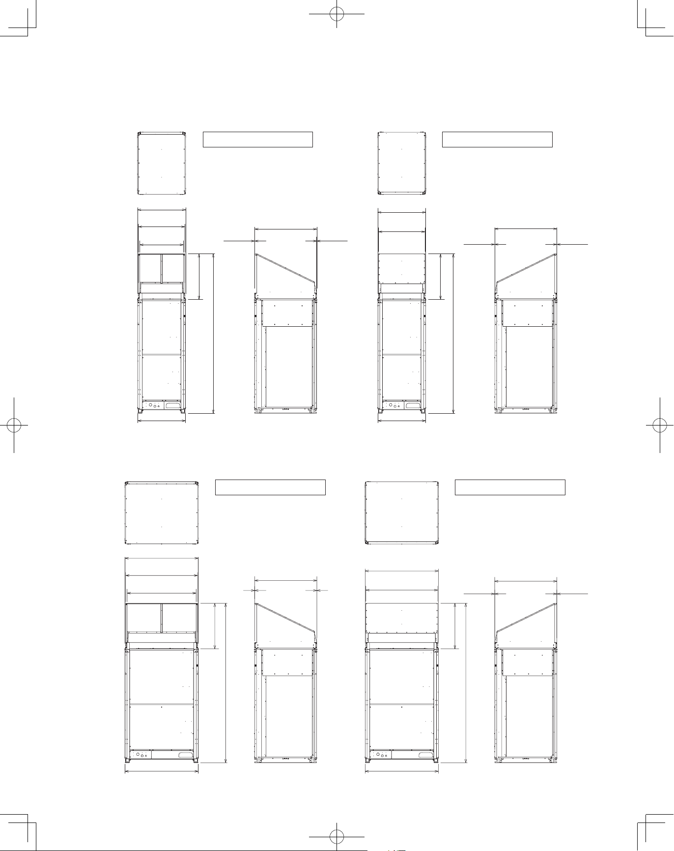
2-5. Dimensions of Wind Ducting
Reference diagram for air-discharge chamber (field supply)
For type 72/96
Note: Can be installed so that the air direction is to the front or rear direction.
unit: in. (mm)
Air direction: Front direction
30-35/64
(776)
29-29/64
(748)
27-43/64
(703)
(733)
28-55/64
(2570)
101-3/16
30-5/16
(770) (770)
Front view Right side view Front view Right side view
39-31/64
(1003)
5/64 (2)3/64 (1)
For type 120/144
Note: Can be installed so that the air direction is to the front or rear direction.
30-35/64
(776)
29-29/64
(748)
30-5/16
Air direction: Rear direction
Top viewTop view
39-31/64
(733)
28-55/64
(2570)
101-3/16
(1003)
unit: in. (mm)
3/64 (1)5/64 (2)
Air direction: Front direction
46-11/16
(1186)
45-19/32
(1158)
43-13/16
(1113)
46-29/64
(1180)
Front view Right side view Front view Right side view
3/64 (1)
(733)
28-55/64
(2570)
101-3/16
39-31/64
(1003)
5/64 (2)
46-11/16
(1186)
45-19/32
(1158)
46-29/64
(1180)
Air direction: Rear direction
Top viewTop view
39-31/64
5/64 (2)
(733)
28-55/64
(2570)
101-3/16
(1003)
19
3/64 (1)
00_302411_EN.indd 19 2018/7/4 13:27:24
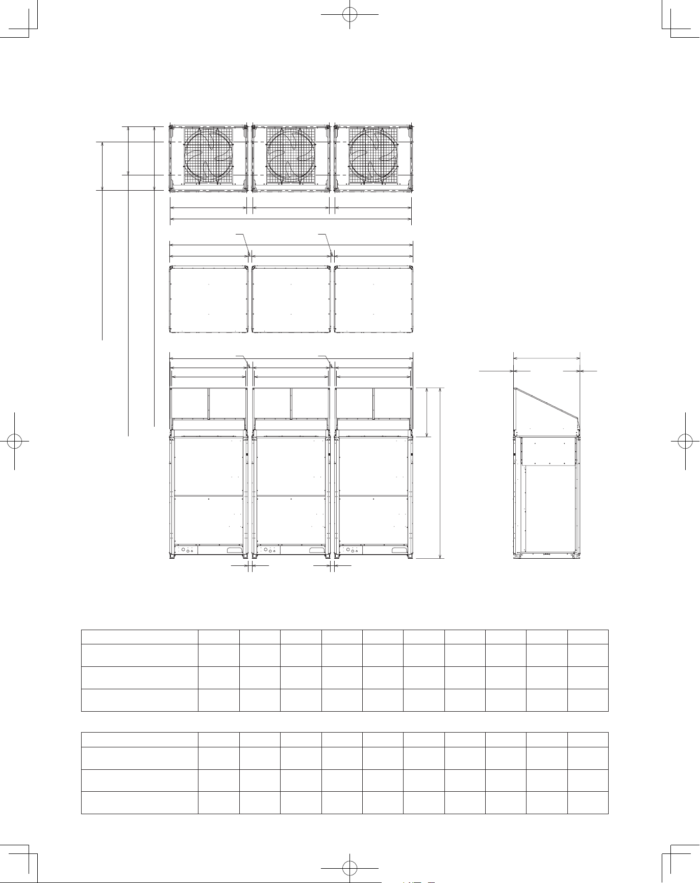
Reference diagram for air-discharge chamber (field supply) (continued)
Combination of units
For various types of combination, refer to Technical Data.
unit: in. (mm)
Top view
(Before installing air-discharge chamber)
J
K
C : 28-47/64 (730) Installation hole pitch
L
M
A : 37-61/64 (964) Installation hole pitch forward tubing direction
B : 28-47/64 (730) Installation hole pitch downward tubing direction
G
E
I I
J
H
F
K
F
L
M
G
E
J
K
Top view
39-31/64
L
M
(733)
28-55/64
(2570)
101-3/16
3/64 (1) 5/64 (2)
(1003)
D
Front view Right side view
According to the installation site, you may choose the setting position in the depth direction of the anchor bolt from “A”, “B” or “C”.
D
Sample of small size models (3 units):
D E F G H I J K L M
Installation hole pitch
A :
B :
Installation hole pitch
C :
Installation hole pitch
2-23/64
(60)
7-3/32
(180)
7-3/32
(180)
2-1/8
(54)
6-27/32
(174)
6-27/32
(174)
95-29/32
(2,436)
105-23/64
(2,676)
105-23/64
(2,676)
3-35/64
(90)
8-17/64
(210)
8-17/64
(210)
94-31/64
(2,400)
103-15/16
(2,640)
103-15/16
(2,640)
3-15/64
(82)
7-61/64
(202)
7-61/64
(202)
29-9/64
(740)
29-9/64
(740)
29-9/64
(740)
30-35/64
(776)
30-35/64
(776)
30-35/64
(776)
29-29/64
29-29/64
29-29/64
Sample of middle size models (3 units):
D E F G H I J K L M
Installation hole pitch
A :
B :
Installation hole pitch
C :
Installation hole pitch
2-23/64
(60)
7-3/32
(180)
7-3/32
(180)
2-1/8
(54)
6-27/32
(174)
6-27/32
(174)
144-21/64
(3,666)
153-25/32
(3,906)
153-25/32
(3,906)
3-35/64
(90)
8-17/64
(210)
8-17/64
(210)
142-29/32
(3,630)
152-23/64
(3,870)
152-23/64
(3,870)
3-15/64
(82)
7-61/64
(202)
7-61/64
(202)
45-9/32
(1,150)
45-9/32
(1,150)
45-9/32
(1,150)
46-11/16
(1,186)
46-11/16
(1,186)
46-11/16
(1,186)
45-19/32
(1,158)
45-19/32
(1,158)
45-19/32
(1,158)
20
(748)
(748)
(748)
27-43/64
(703)
27-43/64
(703)
27-43/64
(703)
43-13/16
(1,113)
43-13/16
(1,113)
43-13/16
(1,113)
00_302411_EN.indd 20 2018/7/4 13:27:27
 Loading...