

Panasonic RR-404 Operating Instructions
Instruction Manual
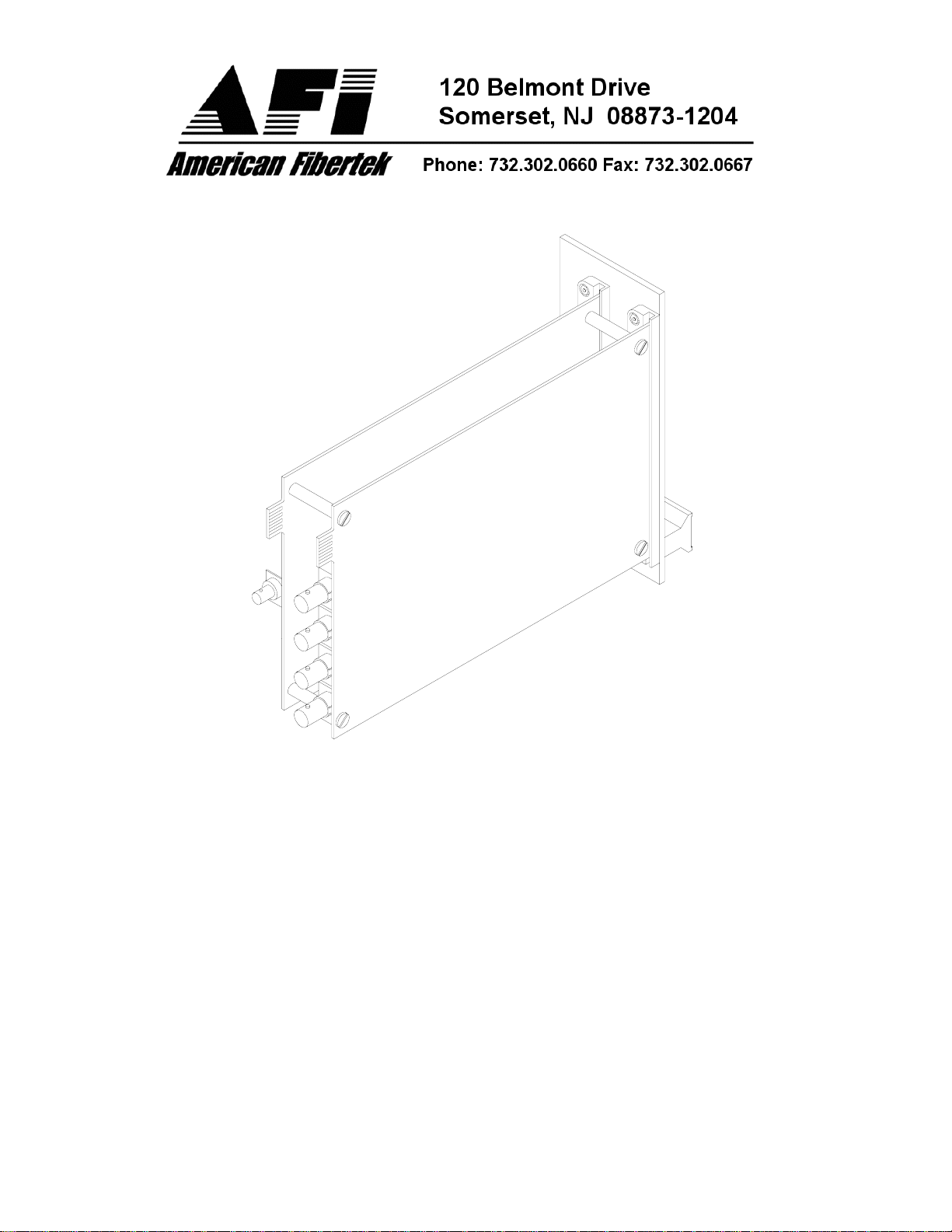
Four Channel Video Receiver
© Copyright 2003, American Fibertek, Inc. 0708JD
RR-404

INSTALLATION AND OPERATION INSTRUCTIONS
INTRODUCTION
Thank you for purchasing your American Fibertek RR-404 multimode four channel video
receiver. Please take a few minutes to read these installation instructions in order to
obtain the maximum performance from this product.
FUNCTIONAL DESCRIPTION
The RR-404 operates as half of a transmitter / receiver pair for the transmission of four
simultaneous, real time, baseband NTSC, PAL, RS170, or RS343 video signals over a
single multimode fiber optic cable. It is designed to operate with the MT-404 or RT-404
four channel video transmitter.
The RR-404 receiver converts a single optical input into a maximum of four video
outputs. The 404 Series product is designed to operate over an optical loss budget
range of 0 to 6 dB with a maximum distance of up to 1.5 km. The RR-404 operates on
50 um or 62.5 um multimode fiber. Refer to the data sheets for detailed performance
specifications.
This unit is designed for rack mounting in any of the three American Fibertek subracks
available. The subrack model numbers are SR-20/1, SR-20R/1, and SR-20/2. Slide in
rack mounting and LED indicators provide for easy installation and monitoring of video
and dc power.
The RR-404 is designed for rack mounting only. For a modular stand alone version
please see the MR-404.
INSTALLATION
THE INSTALLATION OF THIS UNIT SHOULD BE MADE BY A QUALIFIED SERVICE
PERSON(S) AND MUST CONFORM TO ALL LOCAL CODES.
The unit slides into any two adjacent open slots in the SR-20 subrack. Use a small
screwdriver to push and lock the four ¼ turn fasteners into place.
POWER SOURCE
Power to the unit is supplied by the subrack. Please refer to the SR-20 and PSR
instructions for further details.
POWER CONNECTION
Power is supplied to the unit via a four finger backplane connector. The RR-404 can be
inserted into the subrack or removed from the subrack with power applied to the
backplane.
INPUT / OUTPUT CONNECTIONS
The fiber optic connection is made via a ST connector located on the back of the unit.
Be sure to allow sufficient room for the required minimum bend radius of the fiber used.
2
 Loading...