

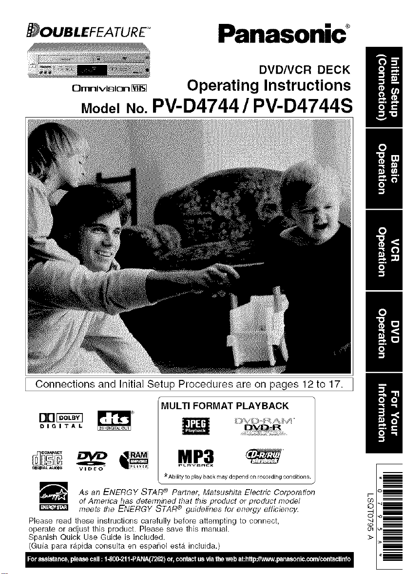
Panasonic PV-D4744S, PV-D4744 Owner’s Manual
Panasonic _
DVDNCR DECK
C}rr_rliv_ion
ModelNo.PV-D4744 / PV-D4744S
Operating Instructions
H
H
H
H
Connections and Initial Setup Procedures are on pages 12 to 17.
MULTI FORMAT PLAYBACK
Drl_
DIGITAL
=lS_ _JmO video
As an ENERGY STAR _ Partner, Matsushita Electric Corporation
of America has detem_ined that this product or product model
meets the ENERGY STAR ® guidelines for energy efficiency.
Please read these instructions carefully before attempting to connect,
operate or adjust this product. Please save this manual.
Spanish Quick Use Guide is included.
(Guia para rapida consulta en espa_ol esta incluida.)
M_P_3
_"Ability to play back may depend on/eco/ding corlditiorl8
B
0
ImportantSafeguardsandPrecautions
TO REDUCE THE RISK OF ELECTRIC SHOCK, FIRE, INJURY TO PERSONS OR DAMAGE TO
THIS PRODUCT, READ AND RETAIN ALL SAFETY AND OPERATING INSTRUCTIONS. HEED ALL
WARNINGS IN THE MANUAL AND OH THE PRODUCT.
I ,NSTALLATION ] I OU OORANTENNA,NSTALLAT,ONI
1 POWERSOURCECAUTION
O_iate ordyfroma powerso_ce _icaled c+_theunRorin thEs
manual Ifnecessary, have your ElectacUtil_ySer_ce
Company orV_deoP_oductsDearervet@_ power sourcein
your hom_
2 POLARIZEDOR GROUNDING PLUG
#,sa safetyfealure,t_s p_educlcomes wi_qe_qe_a polarized
powercord I_ug(or_ blade _ wder thanl_e o_qer),of atr¢ee-
wi_egto_c_ng_ PkO
POLARIZEDPLUGCAUTION:
T_s pklgwillonly _t intoan outer oneway _iyoucannotfully inse_
_qeplug,try reversing _tIf_tstill _ll not f4,have an etectfidan
ins'tallthep_operwalloulet Do notdefeal_ safetyfe_re by
tampe_ngw_qthe pk_g
GROUNDING PLUG CAUTION:
Tf_s _ug wglo4y _tintoa _ree-hete grounding out_ If necessary,
havean etec_dan #stall _qepropel_L Do notdefeat_e safety
feaze by tamperingwith_qepl_
3 POWERCORD
Make sL,repowel cordsareroutedso that_ey are not I_k_yto
haveany_ng reston _em, rollover_tef_,of be inlJte_y of
waling t_af_ Ifan extensioncord _sused, make sue _ta_so
has _e_ a _zed orgroundedp_ugand that_e cordscan
be securelyconnected¸Fiayedcofds, damagedplugs,and
damagedorc_ackedw_reinsu_at_oharehazardousandsheL4d
be _ep_aoedbya qualifiedser_ce t_dan
Overbaded ou_etsand ext_on cords are_re hazardsand
shoL_dbe avoaded
4 DONOT BLOCK VENTILATION HOLES
Veqt_on r4)emgs in_e cabaretreteasehealgeneratedduring
opera,on If_qeyare biocked,hea_b_k_upinside_qeunitcan
causefailures_qalmayresL4tin a _rehazardof heat damage
cassettesor d4so£
Fol protec_on,follow_tese lL_es:
& Nevel covel ven_latlonslols or_ ur_twhitein use,or
_elate _qeun_whenp_acedon a bed, sofa,lug, orother
softsurface
b_ AvoidbuHt4ninstal_a_on,se:h as a bookcaseor le_k,
ur_essproperve+_]at_on_sp_ovtded
5 PLACEMENT:AVOID EXTREMELY HOT LOCATIONSOR
SUDDEN TEMPERATURE CHANGES
Do rtot place_e _t overor pear heater or radiator,in direct
sunIoht, insidedosed veh_ctes,in_gh tempelatu_e[over 104OF
(4d'C)], or in ove_75% humidrty Ifthe t_t _ suddenlymoved
froma coldp_aceto a wa_rnone,mo;stt_emay condense_n_qe
urJtand on_e tape Caus_rE_damage¸Nevel sub,eel_qeL_t
wblat_on,_pect, or p_aceit so that _ surfaceistHUdas
intelpelparism_ be se_ous_ydamaged¸
6 TO AVOID PERSONALINJURY
• DOnotplaceupseculed_est o_a
_Joping_face
• Do notp4ace_s Ltmton any suptx_t_at
is not_lm, tev_, and adequat_y st _ong
The ur_tco_d _l caumngseriousir_u_y
_)a d_d oradleranddarq_geto_qettn_L
• Ana_iaz_e andcartcomb_r_on shoed
be moved withcare¸Quickstops,excessiveforce,and
L'P_vensurfacesrr_y cause _3e_arz:e and cart
comb_a12onto ove_fn
• CarefJ_yfollowalloperatinginstruc_onsand use_e
manufacturer'srecommendedaoc_ssofieswhenopel_ng
_q__t or oonpec_ng_to ar_ o_qerequ_pent
2
1 SAFE ANTENNA AND CABLE CONNECTION
Ifan o_d_ ant_i_ or _e syst_ll is¢_lpe_ed to t]_ eqL_pment, be _::e t_
entenna or cable system _sgrounded so as to prowde some proteceon against
bLilt up sta'ded_alges and voltage _ges
beacon of ante#ha discharge uiit+ conpedeon to groL_dii_g
etectrodes and ieqL_lemen% for the ground_ _ectrode
2 KEEP ANTENNA CLEAR OF HIGH VOLTAGE POWER LINES OR
CIRCUITS
At+ outside antenna _ystef_ should be located well a_tay from power I_es,
erectile Hght or power d_cL_ts and where _twill never co_e into contact with
_ese power soulces if _tsho_d hair+ _ fa_l When instaIHng an ou_de
enter, expense ca_e shoed be takeq to avoid touching powel lines, d_cu_ of
o_el power sources as _q_scoukJ be fetal Because of _e hazards _vo_ved,
entenpe _taHat_ sho_d be leit to a p_ofesslonai
I US,NGTHEUNIT I
t_,e L_',+thas been in storage or moved to a new Ioca_on, refer _ist to t_'e
INSTALLATION sec_on of t_,ese safegualds
1 KEEP THE UNIT AWAY FROM WATER OR MOISTURE OF ANY KIND.
2 IF EQUIPMENT IS EXPOSED TO RAIN, MOISTURE, OR STRONG
IMPACT, L_'_Iug _e L_t and have it inspected by e quaiifled se_ce techn_an
before
3 DURING AN ELECTRICAL STORM
DuIIng a _gh_q_ storm, ',_4tet_'erindoors or or,tdeore, or before leaving _te u_t
unused fof extended p_iiods of _me, d_ect a_equ_pent from L_ powel
souroe as w_l as f_,e8_tenpe and cab{e system
4 WHEN THE UNIT IS PLUGGED IN
• Nevel expose _le unit to ta_nor walel DO NOT OPERATE _ I_d has been
_l_d into _ _t Iilli_d+ate;y unpl_ _e _t, and have it _¢t_d by a
se_,,4cetechnici_n Fire and s_ock hazards can lesult from eteot flcal shorts
caused by I_uld coqtact in_4de
• Never di_ or pu,_ a_/oL_t through op_l_ngs _ L_ L_t Some _te_a_ pads
cai_y _ardous vo_ta_ and conta_ can ca_ _ee_ _k or f_;e hazard
Do not put a_y forelgr_ object on tl-_ d_sct _ay
• AvOkl placing t_le unr_d41ectlyabove or be4ow your TV set as tl'_smay cause
electfi_,l inte#erei_e K_p e_ magnets away from et_tronic eq_pm_t
5 USING ACCESSORIES
Use only accesso_es iecommeqded by _e ma+_f_'t urel to avoid risk of fire,
shock, or o_er hazalds
6 CLEANING THE UNIT
Ut'_lug _e _ Then, use a dean, dry, d_el_cally untreated cloth to geq_y
lemove d_t or debts DO NOT USE cleaning flL_ds, aeloso{s, or forced air that
could over-spray, or seep into t_le unit and cause etecttic_ shock Any substance
st_h as wax, adhesive ta_e, ere may l'r+ar the cab_pet suffice Exposure to
greasy, hurtled, or dusty areas may adversely affect _temai parts
I SERV,CE I
1 DO NOT SERVICE THIS PRODUCT YOURSELF
If, alter carefJly fo_lo_ng t_le detailed opelating instructions, th_s prod_t
does not operate prope_y, do not attempl to open or remove covets, or make
any adjustm_t_ not d_l_ in_e rr_nua] Unpko Lhe _t and conta_ a
qualified servtoe technidan
2 IF REPLACEMENT PARTS ARE REQUIRED
Make sure _te se_wce techniciat_ uses orgy parts spedfied by the
manulaot,llel, or those having t_le same safety characteristics as the ofigil_al
parts The use of unau_or_zed s_st_tutes may result in _re, electric shock,
or o_er hez_rds
3 HAVE THE SERVICE TECHNICIAN PERFORM A SAFETY CHECK
After any se_ce ol lepeils to the L_, request _e s_ce techl_c_n to
conduct a t_lorough safety check as described _ the manufacturel's servtee
literatule to ensule that the _t is in safe operaf_ng cond_lon
SafetyPrecauti0ns/Mesuresdesecurite
To prevent fire or shock hazard, do not expose this equipment to rain
or moisture.
To prevent electric shock, match wide blade of plug to wide slot, fully insert.
AVERTISSEMENT:
Afin de prevenir tout risque d'incendie ou de chocs _lectriques, ne pas
exposer cet appareil a la plumeou a une humidit_ excessive.
ATTENTION :
Pour _viter les chocs _lectriques, introduire la lame la plus large de la
fiche dans la borne correspondante de la prise et pousser jusqu'au fond.
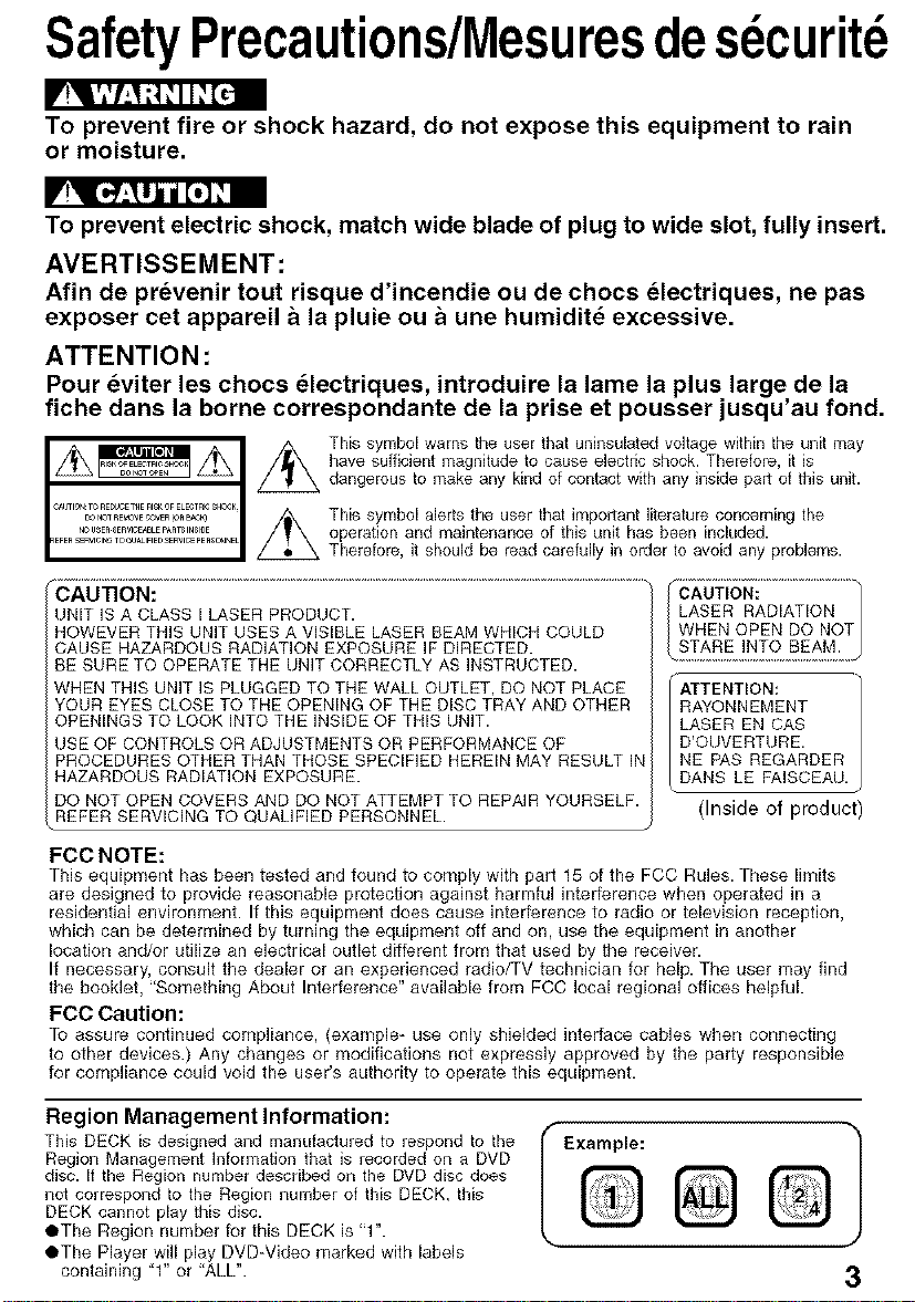
This symbol warns the user that uninsulatad voltage within the unit may
have sufficient magnitude to cause electric shook. Therefore, it is
dangerous to make any kind of contact with any inside part of this unit.
This symbol alerts the user that important literature concerning the
operation and maintenance of this unit has been included.
Therefore, it should be read carefully in order to avoid any problems.
_€-AO0_ 0_ .....................................................................................................................................................................................
UNIT ISA CLASS I LASER PRODUCT.
HOWEVER THIS UNIT USES A VISIBLE LASER BEAM WHICH COULD
CAUSE HAZARDOUS RADIATION EXPOSURE IF DIRECTED.
BE SURE TO OPERATE THE UNIT CORRECTLY AS INSTRUCTED.
WHEN THiS UNIT IS PLUGGED TO THE WALL OUTLET, DO NOT PLACE
YOUR EYES CLOSE TO THE OPENING OF THE DISC TRAY AND OTHER
OPENINGS TO LOOK INTO THE INSIDE OF THIS UNIT.
USE OF CONTROLS OR ADJUSTMENTS OR PERFORMANCE OF
PROCEDURES OTHER THAN THOSE SPECIFIED HEREIN MAY RESULT iN
HAZARDOUS RADIATION EXPOSURE.
DO NOT OPEN COVERS AND DO NOT ATTEMPT TO REPAIR YOURSELF.
REFER SERVICING TO QUALIFIED PERSONNEL.
FCC NOTE:
This equipment has been tested and found to comply with part 15 of the FCC Rules. These limits
are designed to provide reasonable protection against harmful interference when operated in a
residential environment. If this equipment does cause interference to radio or television reception,
which can be determined by turning the equipment off and on, use the equipment in another
location and/or utilize an electrical outlet different from that used by the receiver.
If necessary, consult the dealer or an experienced radio/TV technician for help. The user may find
the booklet, "Something About Interference" available from FCC local regional offices helpful.
FCC Caution:
To assure continued compliance, (example- use only shielded interface cables wben connecting
to other devices.) Any changes or modifications not expressly approved by the party responsible
for compliance could void the user's authority to operate this equipment.
LASER RADIATION
WHEN OPEN DO NOT
(i (ufi6_ ..................................
_ !_2 _M: .....
ATTENTION:
RAYONNEMENT
LASER EN CAS
D'OUVERTURE.
NE PAS REGARDER
DANS LE FAISCEAU.
(Inside of product)
Region Management Information:
This DECK is designed and manufactured to respond to the
Region Management Information that is recorded on a DVD
disc. It the Region number described on the DVD disc does
not correspond to the Region number of this DECK, this
DECK cannot play this disc.
OThe Region number for this DECK is "1".
OThe Player will play DVD-Video marked with labels
containing "1" or "ALL".
Example:
Q
3
Congratulations
on your purchase of one of the most
sophisticated and reliable products on the Playing older or damaged tapes may eventually
market today. Used properly, it will bring you cause video heads to become clogged.
years of enjoyment. Please fill in the information Video Head Clog Sensor r
below. The serial number is oil the tag located woEoH_ACS_¥
on the back of your DECK.
• Date of Purchase
• Dealer Purchased From
• Dealer Address
• Dealer Phone No.
• Model No.
• Serial No
[] Remote Control
[] Batteries 2 "AA"
EUR7724KAO
During playback, this screen
appears if clogging is detected.
To remove screen, press PLAY
on the remote or DECK.
• Use "dry" type head cleaning cassette only.
(Part No. NV-TCL3OPT is recommended.)
• Follow cleaning tape instructions carefully.
Excessive use of tape can shorten head life.
• If head clog symptoms persist, contact your
nearest servicenter by visiting our Web Site
(see p. 61 ).
N_EDCLEb,NIN(_
PEEAqE INSERT HEAD
CLE_*NINGCA_ETrE
ORREFERTO M_NUAL
END PLAY
[] RF Coaxial Cable
LSJA0418
To order accessories,
call toll free
1-800-332-5368.
j 1) Open cover.
2) Insert batteries as
marked.
3) Close cover.
[] Battery replacement caution
• Do not mix old and new batteries.
• Do not mix alkaline with manganese batteries.
• . H m*. o.
Only use tapes with the _ mark in this DECK.
Tape Speed Type of Video Cassette
Setting T120 Tt60 T180
SP 2 Hours
Standard Play) 2 Hours 40 Minutes 3 Hours
SLP
(Super Long Play) 6 Hours 8 Hours 9 Hours
t.] m]=[,j
Use a soft cloth or dusting attachment of a vacuum
cleaner to remove dust from the ventilation holes on
the back sides and bottom of the cabinet.
Plastic surfaces are easily scratched and can be
marred by alcohol and various solvents.
Avoid excessive use of oibbased furniture polishes
since the materials used in the cabinet will
accumulate more dust. We recommend using a
non-abrasive, antistatic cleaner and polisher.
*. - . . e . L " - ;
Diqital Auto Picture
Automatically controls the video output signal for
less noise depending on the tape condition.
Diaita] Auto Trackina
Continuously analyzes the signal and adjusts for
optimum picture quality.
Manual Trackina Control
(to reduce picture noise)
Use during Playback and Slow Motion mode to
reduce picture noise.
Press CH (TRACKING) A/y on the remote control
or on DECK until the picture clears up.
To return to Auto Tracking, press POWER off, then
on again a few seconds later.
V-Lock Control tto reduce picture iittert
In Still mode, CH (TRACKING) _JV operate as a
V-Lock control.
4
il
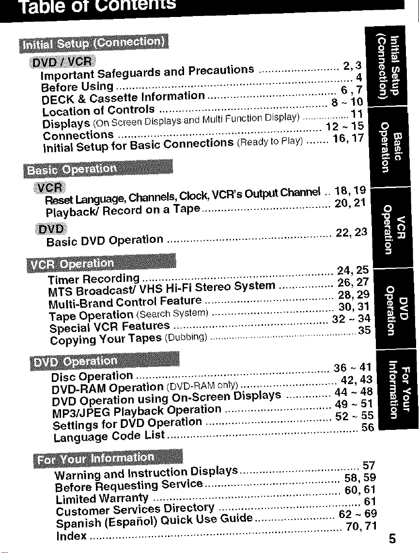
Important Safeguards and Precautions ......................... 2, 3
Before Using ......................................................................... 4,
DECK & Cassette Information ........................................ 6,7
Location of Controls .................................................... 8 ~ 10
Displays/on Screen Displays and Multi Function Display) ............. 11 m
Connections ............................................................... 12 ~ 15
Initial Setup for Basic Connections (Readyto Play) ....... 16, 17
m
=
Reset Language, Channels, Clock, VCR's Output Channel .. 18, 19
Playback/Record on a Tape ........................................ 20, 21
Basic DVD Operation ................................................... 22, 23
Timer Recording ........................................................... 24, 25 m
MTS Broadcast/VHS Hi-Fi Stereo System ................. 26, 27
Multi-Brand Control Feature ........................................ 28, 29
Tape Operation (Seat'chSystem) ...................................... 30, 31
Special VCR Features ................................................ 32 ~ 34
Copying Your Tapes (Oubb(_g)...................................................... 35
8
Disc Operation ............................................................ 36 ~ 41
DVD-RAM Operation (DVD-RAM only) .............................. 42, 43
DVD Operation using On-Screen Displays .............. 44 ~ 48 I
MP3/JPEG Playback Operation ................................. 49 - 51
Settings for DVD Operation .......................................
Language Code List ........................................................... 56
Warning and Instruction Displays ..................................... 57
Before Requesting Service .......................................... 58, 59
Limited Warranty .......................................................... 60, 61
Customer Services Directory ............................................ 61
Spanish (Espahol) Quick Use Guide ......................... 62 ~ 69
Index .............................................................................. 70, 71
5
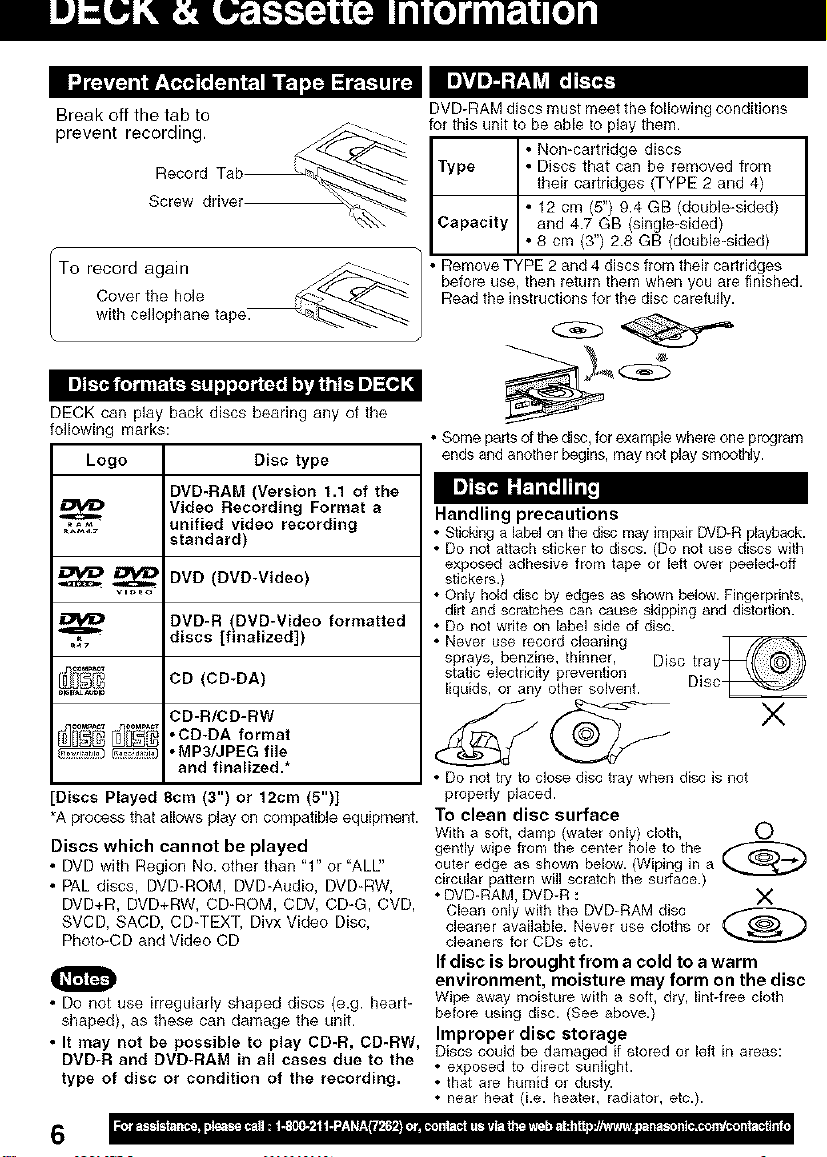
Break off the tab to
prevent recording,
Screw driver
"To record again _-- /
wC,ti_eret,,hopI:',a°'netape__ /
I I]l_Ji 1,1/ilt:,l 1.11.1II[ ,Iel/i_rll ;'_'f]t;'il_l I] _1,] ,!
DECK can play back discs bearing any of the
following marks:
Logo Disc type
DVD-RAM (Version 1.1 of the
.,_f_% unified video recording
_i_ CD (CD-DA)
[Discs Played 8cm (3") or 12cm (5")]
•A process that allows play on compatible equipment.
Discs which cannot be played
• DVD with Region No. other than "1" or "ALU'
• PAL discs, DVD-ROM, DVD-Audio, DVD-RW,
DVD+R, DVD+RW, CD-ROM, CDV, CD-G, CVD,
SVCD, SACD, CD-TEXT, Divx Video Disc,
Photo-CD and Video CD
• Do not use irregularly shaped discs (e.g. heart-
shaped), as these can damage the unit.
• It may not be possible to play CD-R, CD-RW,
DVD-R and DVD-RAM in all cases due to the
type of disc or condition of the recording.
Video Recording Format a
standard)
_ DVD (DVD-Video)
DVD-R (DVD-Video formatted
discs [finalized])
CD-R/CD-RW
• CD-DA format
_ .MP3/JPEG file
and finalized.*
DVD-RAM discs must meet the following conditions
for this unit to be able to play them.
Type • Discs that can be removed from
Capacity
• Remove TYPE 2 and 4 discs fiom theil cartridges
before use, then letum them when you are finished.
Read the instructions for the disc carefully.
• Some pads of the disc, for example where one program
ends and another begins, may not play smootNy.
• Non-cartridge discs I
their cartridges (TYPE 2 and 4)
• 12 cm (5") 9.4 GB (double-sided)
and 4.7 GB (single-sided)
• 8 cm (3") 2.8 GB (double-sided)
Im]_'_ I:I_'BIII_j
Handling precautions
• Sticldng a label on the disc may impair DVD-R playback.
• Do not attach sticker to discs. (Do not use discs with
exposed adhesive from tape or left over peeled-off
stickers.)
• Only hold disc by edges as shown below. Fingerprints,
dirt and scratches can cause skipping and distortion.
• Do not write on label side of disc.
• Never use record cleaning
sprays, benzine, thinner, Disc tray
static electricity prevention
liquids, or any other solvent. Disc
• Do not try to close disc tray when di_c is not
properly placed.
To clean disc surface
With a soft, damp (water only) cloth, 0
gently wipe from the center hole to the
outer edge as shown below. (Wiping in a
circular pattern will scratch the surface.)
• DVD-RAM, DVD-R : X
Clean only with fhe DVD-RAM disc _-_
cleaner available. Never use cloths or
cleaners for CDs etc.
If disc is brought from a cold to a warm
environment, moisture may form on the disc
Wipe away moisture with a soft, dry, lint-free cloth
before using disc. (See above.)
Improper disc storage
Discs coulct be damaged if stored or left in areas:
• exposed to direct sunlight.
• that are humid or dusty.
• near heat (i.e. heater, radiator, etc.).
I
6
Power Sou t_;e_
Power Consumption:
Video Signal:
Video Recording System:
Audio Track:
Tuner
Broadcast Channels:
CABLE Channels:
Input/Output Terminal:
Input Terminal:
Output Terminal:
Operating Temperature:
Operating Humidity:
Weight:
Dimensions:
Discs Played
(1) DVD-Video Disc
DVD-RAM Disc
(2) Compact Disc
(CD-DA)
(CD-R/CD-RW, MP3, JPEG)
Digital Audio Output:
Pickup:
120 V AC, 60 Hz
Power On: Approx. 28 watts, Power Off: Approx. 0.85 watts
EiA Standard NTSC color
4 rotary heads helical scanning system
1 track (Normal), 2 channel (Hi-Fi Audio Sound)
VHF 2 - 13, UHF 14 _ 69
Midband A through i (14 - 22), Superband J through W (23 - 36)
Hyperband AA _ EEE (37 - 64), Lowband A-5 - A-1 (95 - 99)
Special CABLE channel 5A (01), UJtraband 65 - 94, 100 - 125
Audio/Video Line Input/Output, RF Input/Output
Audio/Video Line input (Front)
S-Video Output (DVD only), Component Video Output (DVD only)
Audio Output 2 (L), (R)
5 C - 40°0 (41 F _ 104 F)
10%-75%
3.85 k_z(8.5 Ibs).
430 (W) x 95 (H) x 273 (D) mm
16-15/16" (W) x 3-3/4" (H) x 10-3/4" (D) inch
5" (12 cm) single-sided single-layer
5" (12 cm) single-sided doubleqayer
5" (12 cm} double-sided double-layer (one layer per side)
3" (8 cm) single-sided single-layer
3" (8 cm) single-sided doubleqayer
3" (8 era} double-sided double-layer (one layer per side)
5" (12 cm} 9.4 GB (double-sided) and 4.7 GB (single-sided)
3" (8 era} 2.8 GB (double-sided)
5" (12 cm) disc
3" (8 era) disc
Digital Optical Connector
Wavelength: 655 nm (DVD), 790 nm (CD)
Laser power: CLASS II
Note: * Designs and specifications are subject to change without notice.
Angle: Some DVD discs feature scenes simultaneously shot from different angles.
Chapter Number:Titles are subdivided into numbered sections. You can quickly search for
DVD: A high-density optical disc on which high-quality pictures and sound have
Subtitles: Written dialogue which appears at the bottom of the screen.
Time Number: The elapsed play time from the start of a disc or title. Use to quickly find
Title Number: For DVD discs with two or more titles, the title is numbered as title 1, title 2, etc.
Track Number: Numbers assigned to tracks on CDs to allow specific tracks to be quickly
Apparatus Claims of U.S. Patent Nos. 4,631,603, 4,577,216, 4,819,098 and 4,907,093,
licensed for limited viewing uses only.
P_ ....
This roduct incorporates copyright protection technology that is Erotected by method claims of
other rights owners. Use of this copyright protection technology must be authorized by Maerovision
i
Corporation, and is intended for home and other limited viewing uses only unless otherwise
The ANGLE button can be used to view the scene from different angles.
(ANGLE Indicator lights on DECK when a scene recorded at different
angles is detected.)
a favorite scene using these numbers.
been digitally recorded. DVD incorporates video compression technology
(MPEG II) and high-density recording technology which allow entire
movies to be recorded with incredible playback quality.
scenes. (May not work with some discs.)
located.
rights owned _y Macrovlslon Corporahon and
o orsieng,,ee,ngordisassembly,sprohibited
7
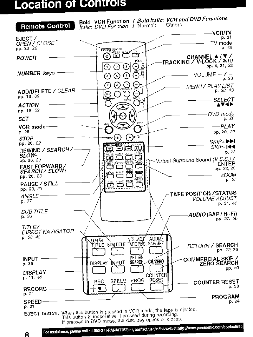
Bold: VCR Function / Bold Italic: VCR and DVD Functions
Italic: DVD Function I Normal: Others
EJECT / / p_21
OPEN! CLOSE
pp, 20, 22 TV mode
POWER
©®®'
CHANNEL A/, /
/ V-LOCK / _ 10
NUMBER keys
®®@
ADD/DELETE / CLEAI
pp, 19, 39
VOLUME+/ -
ACTION
pp. 18. 52
SET
VCR mode
p. 28
STOP
pp. 20, 22
REWINC
SLOW-
pp, 20, 23
FAST FO
SEARCH/SLOW+
pp, 20, 23
PAUSE / STILL
pp, 20, 2,3
ANGLE
p 37
SUB TITLE
p 36
TITLE/ ,'
DIRECT NA VIGA TOR _ "
p 38, 42
TITLE TAPEP
/ p. 28
TAPE POSITION/STATUS
VOLUME ADJUST
VCR/TV
p. 28
pp, 4, 21, 22
AYLIST
p38.43
SELECT
A_41b
DVD mode
PLA Y
pp. 20, 22
SKIP+
SKIP- HI<
p23
(v.s.s.) /
ENTER
pp 23, 2_
ZDOM
p 37
p, 31, 41
(SAP / Hi-Fi)
pp. 27, 3d
pp. 22, 30
INPUT- _ETL_
p. ss IERCIAL SKIP /
ZERO SEARCH
DISPLAY pp. 30
p, 11, 44 COUNTER
REC SPEED PROG RESET
RECORD p. 30
,o.21
SPEED PROGRAM
p. 21 p. 24
EJECT button: Wl'_en 1hi5 buttor_ is pressed in VCR mode, the tape is ejected.
This button is inoperative if pressed during recording.
It pressed in DVD mo_e, _he dis_ t_ay operas or closes.
=
Bold: VCR Function
Italic: DVD Function
Bold ltalic: VCR and DVD Functions
Normal: Others
PLAY
p. 20
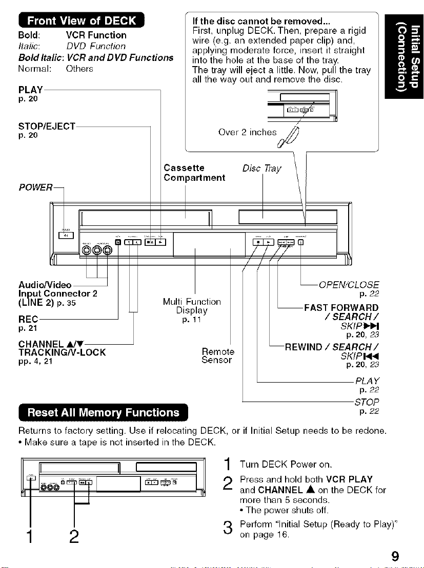
If the disc cannot be removed...
First, unplug DECK, Then, prepare a rigid
wire (e.g. an extended paper clip) and,
applying moderate force, insert it straight
into the hole at the base of the tray.
The tray will eject a little, Now, pull the tray
all the way out and remove the disc.
STOP/EJECT
p. 20
Casms;ttrfment Disc Tray \
POWER_I _
Audio/Video
Input Connector 2
(LINE 2) p. 35
REC
p. 21
CHANNEL_JT
TRACKING/V-LOCK Remote
pp. 4,21 Sensor
Multi Function
Display
p, ll
Over 2 inches
,I , \ '!R
, , R EIoPN/CLOSE
p. 22
FAST FORWARD
/ SEARCH /
SKIPI_I_I
p. 20, 23
REWIND / SEARCH/
SKIPI<NI
p. 20, 23
PLAY
p. 22
STOP
p. 22
Returns to factory setting, Use if relocating DECK, or if Initial Setup needs to be redone,
• Make sure a tape is not inserted in the DECK.
] Turn DECK Power on.
E
2
,'_ Press and hold both VCR PLAY
(-..
and CHANNEL • on the DECK for
more than 5 seconds.
• The power shuts off.
3 Perform "Initial Setup (Ready to Play)"
on page 16,
9
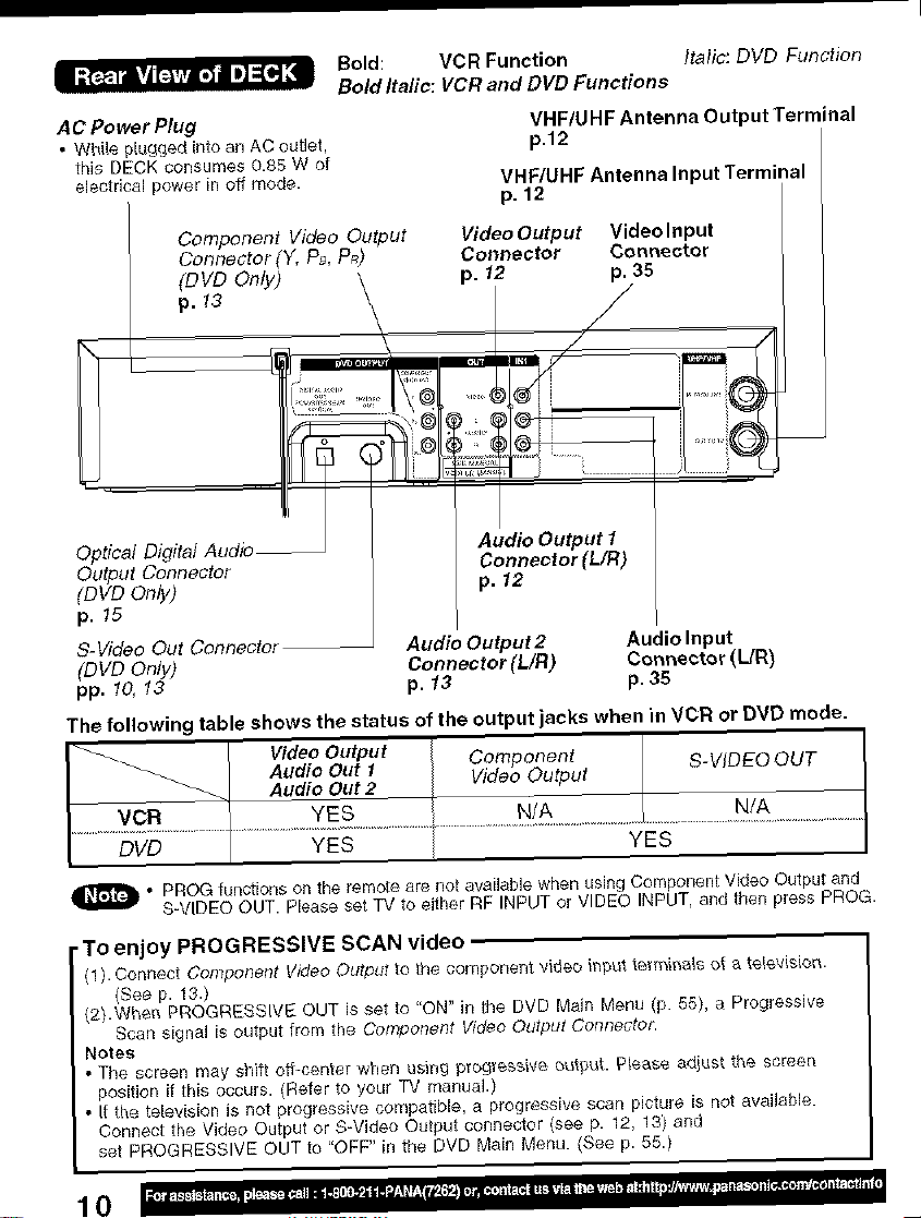
Bold: VCR Function Italic: DVD Function
Bold Italic: VCR and DVD Functions
AC Power Plug
• While pl_lgged into ar_AC outlet,
this DECK consumes 0.85 W of
electrical power in off mode.
Component Video Output
Connector(Y, PB,P_)
(DVD Only)
Video Output Video Input
Connector Connector
p. 12 p. 35
VHF/UHF Antenna Output Terminal
p.t2
VHF/UHF Antenna Input Terminal
p. 12
p. 13
f
Optical Digital Audio_
Output Connector
(DVDOnly)
p. 15
S- Video Out Connector
(DVD Only)
pp. 10, 13
The following table shows the status of the output jacks when in VCR or DVD mode.
I Video Output Corn CheRt
I Audio Out 1 . P S-VIDEOOUT
Audio Out 2 Video Output
Audio Output 2 Audio Input
Connector (UR) Connector (L/R)
p. 13 p. 35
Audio Output t
Connector (L/R)
p. 12
I
DVD [ YES YES
_ o PROG functions on the remote are not available when using Compor_ent Video Output and
• To enjoy PROGRESSIVE SCAN video
(1). Connect Componerlt Video Output to the coi_qponent video inptit tem_ii-_a_sot _ te_÷visioi_.
(2).Whei_ PROGRESSIVE OUT is set to "ON" in the DVD Main Menu (p. 55), a Progressive
Notes
• The screen may shift ott-center when using p_ogTessive, _utput, Please adiust the screen
position if tffis occurs. (Refer to your TV manual.)
• It the television is not progressive compatible, a progressive scan picture is not availaNe.
Connect the Video Output or S-Video Output connector (see p. 12, 13) and
set PROGRESSIVE OUTto "OFF" in the DVD Main Menu. (See p. 55.)
S-VIDEO OUT. Please set TV to either RF INPUT or VIDEO INPUT, _nd then press PROG.
(See p. 13.)
Scan signal is output from the Component Video Odtput Cont_ecto&
10
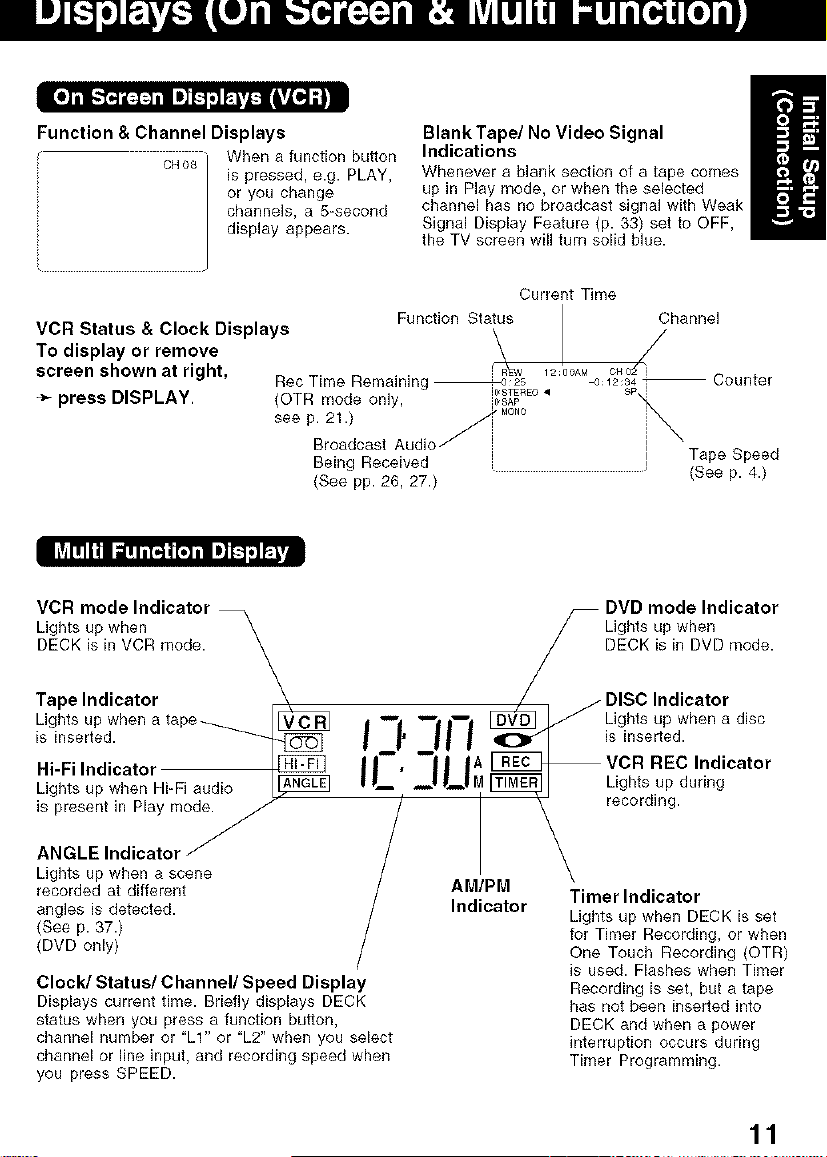
Function & Channel Displays
c_o_ _ Wben a function button
is pressed, e.g. PLAY,
or you change
channels, a 5=second
display appears.
VCR Status & Clock Displays
To display or remove
screen shown at right,
_- press DISPLAY.
IIAIllli1 a=nn[_i[.qii =]L'4r;']_._
BlankTape/No Video Signal
Indications
Wbenever a blank section of a tape comes
up in Play mode, or when the selected
channel has no broadcast signal with Weak
Signal Display Feature (p. 33) set to OFF,
the TV screen will turn solid blue.
Current Time
Function Status
Rec Time Remaining ht,STEREO•
(OTR mode only, I_SAP
seeP2:'dcastAud,of....
Being Received
(See pp. 26, 27.)
Channel
/
Tape Speed
(See p. 4.)
VCR mode Indicator
Ligbts up wben \
DECK is in VCR mode.
\
Tape Indicator
Lights up when a tape ____
is inserted.
Hi-Fi Indicator
Lights up
i;G:'2:indi_:tYori°_ "/
Lights up when a scene
recorded at different
angles is detected.
(Bee p. 37.)
(DVD only)
Clock/Status/Channel/Speed Display
Displays current time. Briefly displays DECK
status when you press a function button,
channel number or "LI" or "L2" when you select
channel or line input, and recording speed when
you press SPEED.
when Hi-Fi audio A_
/
d m'l "--'| Iwl [_ _ Lights up when a disc
I I' II I isinse ed.
I1-, |A VCR REC Indicator
II,_ _ P_lM_Ligbtsupdudng
/ AM_PaMt°r _, sdo_e r_dgi:i';i!i:, )
DVD mode Indicator
LDight_<uPiwhDe_Dmode"
DISC Indicator
' recording,
Recording is set, but a tape
has not been inserted into
DECK and when a power
interruption occurs during
Timer Programming.
11
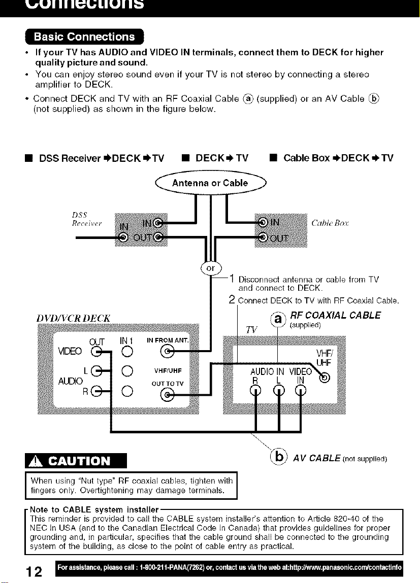
• If your TV has AUDIO and VIDEO IN terminals, connect them to DECK for higher
quality picture and sound.
• You can enjoy stereo sound even if your TV is not stereo by connecting a stereo
amplifier to DECK.
• Connect DECK and TV with an RF Coaxial Cable _) (supplied) or an AV Cable _
(not supplied) as shown in the figure below.
• DSSReceiver =I,DECK=I, TV • DECK_TV • Cable Box ,I, DECK,_TV
Antenna or Cable
DSS'
Receiver (Table flov
Disconnect antenna or cable from TV
and connect to DECK.
2 Connect DECK to TV with RF Coaxial Cable.
DVI)/VCR DECK
RF COAXIAL CABLE
(supplied)
_@ AV CABLE(not supp((ed)
f,WhgtYsTn; 't''g l,7o,,w'th
• Note to CABLE system installer
This reminder is provided to call the CABLE system installer's attention to Article 820-40 of the
NEC in USA (and to the Canadian Electrical Code in Canada) that provides guidelines for proper
grounding and, in particular, specifies that the cable ground shall be connected to the grounding
system of the building, as close to the point of cable entry as practical.
12
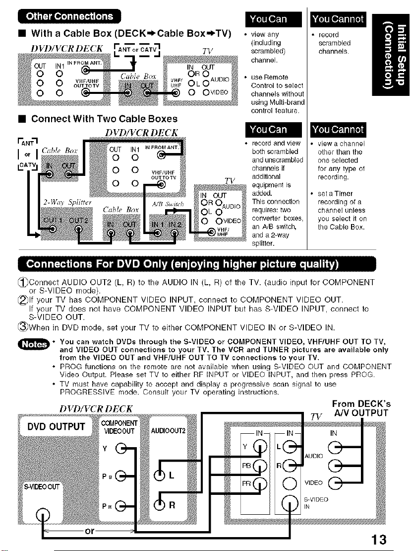
• With a Cable Box (DECK=l_Cable Box,_TV) • v+ewany
D VD/VCR l l_ CK TV scrambled)
Onc]uding
channel
• use Remote
Control to select
channels without
using Multi-brand
cont£ol feature.
record
scrambled
channels.
• Connect With Two Cable Boxes
DVD/VCR DECK
• record and view
TV
both scrambled
and uRscrarnb]ed
channels if
ddditiona]
equipment is
added.
This connection
requires: two
oonveddr boxes
an A/B switch,
and a 2-way
splitter.
view a channel
otherthanthe
ore selected
for any type of
recording.
set a Timer
recording of a
channel unless
you select it on
the Cable Box.
[l';.],lil.--:,,ll[.],l-'_ i_"r_ i1_'11][i]"1111"j[1:4_[_ _'_li[:]l ,]_llll[:i.lIP-Ili;'|
_)Connect AUDIO OUT2 (L, R) to the AUDIO IN (L, R) of the TV. (audio input for COMPONENT
or S-VIDEO mode).
@)If your TV has COMPONENT VIDEO INPUT, connect to COMPONENT VIDEO OUT.
If your TV does not have COMPONENT VIDEO INPUT but has S-VIDEO INPUT, connect to
S-VIDEO OUT.
_3_When in DVD mode, set your TV to either COMPONENT VIDEO IN or S-VIDEO IN.
_D • You can watch DVDs through the S-VIDEO or COMPONENT VIDEO, VHF/UHE OUT TO TV,
and VIDEO OUT connections to your TV. The VCR and TUNER pictures are available only
from the VIDEO OUT and VNE/UHE OUT TO TV connections to your TV.
• PROG functions on the remote are not available when using S-VIDEO OUT and COMPONENT
Video Output. Please set TV to either RF INPUT or VIDEO INPUT, and then press PROG.
• TV must have capability to accept and display a progressive scan signal to use
PROGRESSIVE mode. Consult your TV operating instructions.
DVD/VCRDECK From DECK's
7_/ A/V OUTPUT
13
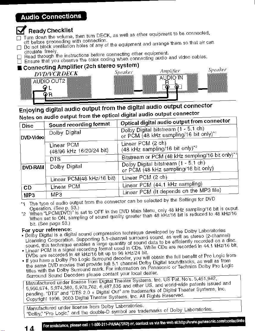
_/_ Ready Checklist
[] Turn down the volume, then turn DEDK, as well as othe_ equipl_ent to be connected,
oil beto_e proceeding with connection.
[] Do not block ventilation holes of any of the equipment and arrange them so that ai[ can
circulate tree_y.
[] Read through the instructions before connecting other equipment.
D Ensure that you observe the ¢o_or coding when connecting audio and video cables.
• Connecting Amplifier (2ch stereo system)
DVD/VCRDF_ K Speal,_r
Enjoying digital audio output from the digital audio output connector
Notes on audio output from the optical digital audio output connector
Disc
DV_d_
DVI_RAM
DD
MP3
"1 The type of audio output from the connector can be selected by the Settings for DVD
Operation. (See p. 53.)
"2 When 'LPCM{DVDy' is set to OFF in the DVD Main Menu, only 48 kHz sampling/16 bit is ouput.
When set to ON, sampling of sound quality greater than 48 kHz/16 bit is reduced to 48 kHz/16
bit. {See page 53.)
For your reference:
• Dofby Digital is a digital sound compression tecSnique developed by the Dolby Laboratories
Licensing Corporation. Supporting 5.1-channel suffot_nd scrod, as we_[ as stereo (2-charlnel)
so_d, this technique enables a large quantity of sound data to be efficiently recorded on a disc.
• Linear PCM is a signal recording format used in CDs. While CDs are recorded in 44.1 kHz/16 bit,
DVDs are recorded in 4B kHTJt6 bit up to 96 kHz/24 bit,
• If you have a DoJby Pro Logic Surround decoder, you wi!l obtain the fu_Jbene#l of Pro Logic #urn
the same DVD movies that provide full 5.1 channel Do,by Digital soundtracks, as well as from
titles with _te Oolby Surround mark. For fluorination on Panasonic or Tectmics Do/by Pro Logic
Surround Sound Decoders please contact your local dealer.
Sound recording format Optical digital audio output from connector
Dolby Digital Dolby Digital bitstream (1 - 5.1 ch)
or PCM (48 kHz sm'npling/16 bit only)*_
Linear PCM Linear PCM (2 ch)
(48/96 kNz f 6/20/24 bit) (48 kHz samplJng/l 6 bit only) .2
DTS Bitstream or PCM 148 kHz sampling/16 bit only) _'
Dolby Digital Polby Digital bitstream (1 - 5.1 ch)
or PCM (48 kHz sampling/16 bit only)
Linear PCM(48 kHz/16 bit) Linear PCM (2 ch)
Linear PCM Linear PCM (44.1 kHz sampling)
MP3 Linear PCM (It depends on the MP3 file)
5,956,674, 5,974,330, 5,978,762, 6,487,535 and other US. and world-wide patents issued and
pending. "DTS" and "DTS 2.0 + Digital Out" are trademarks of Digital Theater Systems, inc.
I Manufactured under license from Digital Theater System$, inc. US P_t. No's. 5,451,942,
Copyright 1996, 2003 Digital Theater Sy_tems,,,_tInc. A_l R(ghts Reserved.
Manufactured under license from Dolby Laboratories.
["Dolby_' "Pro Logic," and the double-D symbol are trademarks of Dolby Laboratories.
t.4
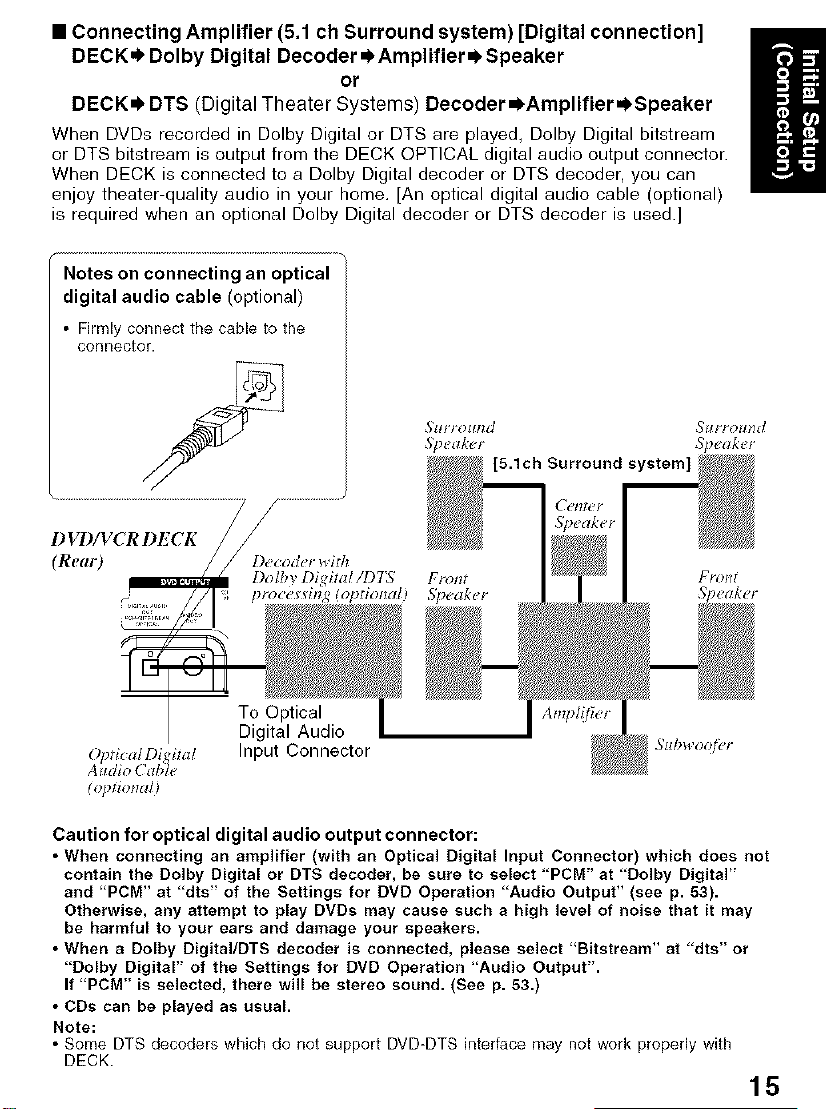
• Connecting Amplifier (5.1 ch Surround system) [Digital connection]
DECK.I. Dolby Digital Decoder =_AmplifierOSpeaker
or
DECK=) DTS (Digital Theater Systems) Decoder =)Amplifier._Speaker
When DVDs recorded in Dolby Digital or DTS are played, Dolby Digital bitstream
or DTS bitstream is output from the DECK OPTICAL digital audio output connector.
When DECK is connected to a Dolby Digital decoder or DTS decoder, you can
enjoy theater-quality audio in your home, [An optical digital audio cable (optional)
is required when an optional Dolby Digital decoder or DTS decoder is used.]
Notes on connecting an optical
digital audio cable (optional)
• Firmly connect the cable to the
connector.
DVD/VCRDECK
(Real9
Dolby Digital/1)7"5 Front Front
pro€e lng (optiorzal) 5_eaker Speaker"
To Optical
Digital Audio
O_ficalDijital Input Connector
Alll O(d _1€
(lfl_tiotldl)
Caution for optical digital audio output connector:
• When connecting an amplifier (with an Optical Digital Input Connector) which does not
contain the Dolby Digital or DTS decoder, be sure to select 'PCM" at "Dolby Digital"
and 'PCM" at "dts" of the Settings for DVD Operation "Audio Output" (see p. 53).
Otherwise, any attempt to play DVDs may cause such a high level of noise that it may
be harmful to your ears and damage your speakers.
• When a Dolby Digital/DTS decoder is connected, please select 'Bitstream" at "dts" or
"Dolby Digital" of the Settings for DVD Operation 'Audio Output".
If PCM" is selected, there will be stereo sound. (See p. 53.)
• CDs can be played as usual.
Note:
• Some DTS decoders which do not support DVD-DTS interface may not work properly with
DECK.
15
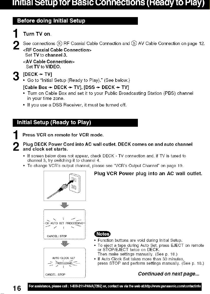
IP,p+'_1,+]i[:+]l,o[.] iil,_i im"i'_I_"I ll,.++,j'_| wi
Turn TV on.
1
See connections @ RF Coaxial Cable Connection and @ AV Cable Connection on page 12.
<BF Coaxial Cable Connection>
Set TVto channel 3.
<AV Cable Connection>
Set TV to VIDEO.
[DECK ÷ TV]
• Go to "Initial Setup (Ready to Play)." (See below.)
[Cable Box -_ DECK -_ TV], [DSS ÷ DECK -_ TV]
• Turn on Cable Box and set it to your Public Broadcasting Station (PBS) channel
in your time zone.
• If you use a DSS Receiver, it must be turned off.
Ii iiiii R i-"F4 Ifl_l ;_ L,=€,n d R'_
Press VCB on remote for VCB mode.
Plug DECK Power Cord into AC wall outlet. DECK comes on and auto channel
and clock set starts.
• If screen below does not appear, check DECK - TV connection and, if TV is tuned to
channel 3, try switching itto channel 4.
• To change VCR's output channel, please see "VCR's Output Channel" on page 19.
Plug VCR Power plug into an AC wall outlet.
16
i _ \ I f/
_CH AUTO SET PROCEEDING_
CANCEL : _TOP
AUTO CLOCK SET
pROCEEDiNG
I / i _-- ,
CANCEL:STOP
0
• Function buttons are void during Initial Setup•
• To eject a tape during Auto Set, press EJECT on remote
or STOP/EJECT twice on DECK.
Then make settings manually. (See p. 18.)
• If Auto Clock Set takes more than 30 minutes,
press STOP and perform settings manually. (See p. 18.)
Continued on next page,,,
,_vsE_ _E zoo _r_r_
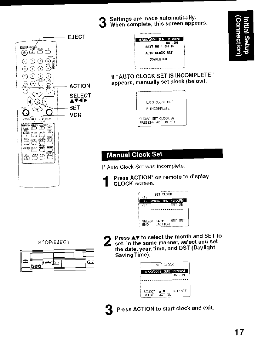
EJECT
When complete, this screen appears.
Settings are made automatically, l
If "AUTO CLOCK SET IS INCOMPLETE"
appears, manually set clock (below).
[_ ENCONFLETE
I AUTO CLOCK SET
PLEASE SET CLOCK 8Y
pRESSING ,_GTION _Ey
li_l_lil!k.1 11_r,] _;Ib'l"_
If Auto Clock Set was )ncomp)ete.
Press ACTION _on remote to display
CLOCK screen.
STOP/EJECT
Press &T to seleot the month and SET to
set. In the same manner, select and set
the date, year, time, and DST (Daylight
Saving Time).
SET CLOCK
....................
SELECT • • _ET SET
;_ START :A_T[ON ....
DST: 01_
Press ACTION to start clock and exit.
17
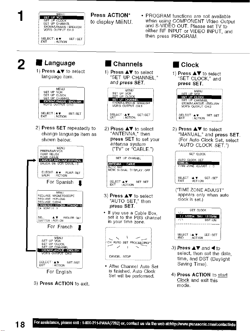
1
_4ENU Press ACTION*
SETUPCLOCK tO display MENU
SET UP CHANNEL
IDIOM_NGUE ; ENGUSH i!_ VORS OUTPUT CH:3
EXiT _C'T_ON i
• PROGRAM functions are not available
when using COMPONENT Video Output
and S-VIDEO OUT. Please set TV to
either RF INPUT or VIDEO INPUT, and
ther_ press PROGRAM•
2 • Language
1) Press &_" to select
language item.
_ENU
SET UP VCR
SET UP CLOCK
_ISET UP CHANNEL
• EXIT RACTION . .
2) Press SET repeatedly to
change language item as
shown below,
FrJAR RELO#
For Spanish ,_ i SELECT_*_ SETS_
i_EGLAGMAGNETOSCQpE 3) Press A_' to select
i_e_ _:_.'_ "AUTO SET," then
i_4 GLAG CANA_
_NU
For French ]
• Channels
1) Press _,V to select
"SET UP CHANNEL
and press SET.
i IDIOM&&AN_b_ :ENGU_4
i VCR,£ OUTPUT OH:3
i S_L_Cq'_A'f SET:S_T i
DqT :A_T_ON
2) Press A,T to select
'ANTENNA," then
press SET to set your
a I] t_]3 [_c3 sys_eITI
("TV" or "CABLE•'
iAuro SET
press SET.
• If you use a Cable Box,
set it to the PBS cha_nel
in your time zone.
• Clock
1) Press _V to select
'SET CLOCK," and
press SET.
i _T UP v(:n
i SET UP CHANNEL
i VOR'S OUTf_UT CH:3
EXfT : ACTION
2) Press _' to select
'MANUAL," and press SET.
(For Auto Clock Set, select
"AUTO CLOCK SET." /
"TIME ZONB AD,_UST"
appears only when auto
clock is set.)
i SELECT :_,V SET:SET
18
For English
3) Press ACTION to exit.
; CAN_EL:STOP
• After Channel Auto Set
is finished, Auto Clock
Set will be performed.
3} Press &_ and • to
select, then set the date,
time, and DST (Daylight
Saving Time}.
4) Press ACTION to start
Clock and exit this
mode.
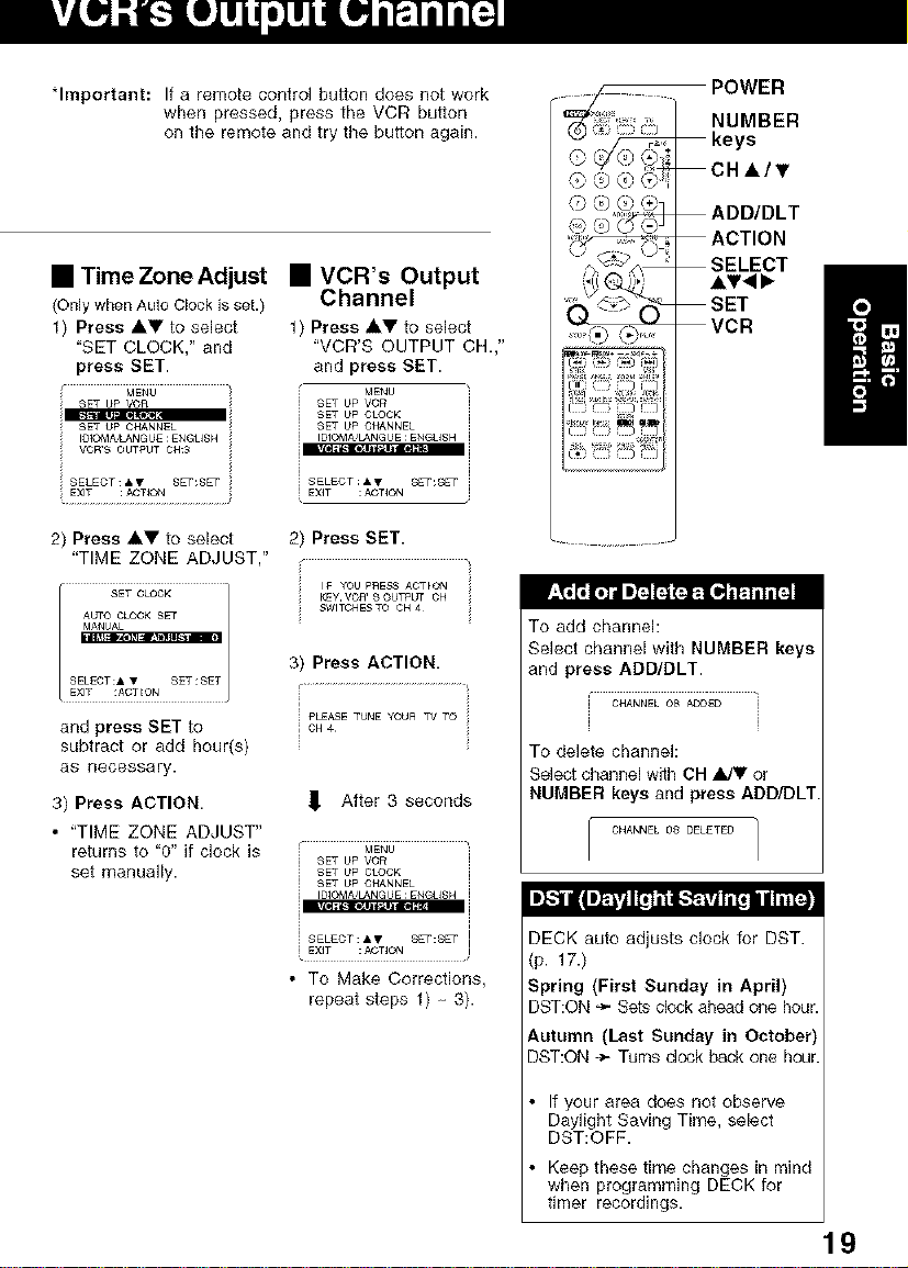
"Important: If a remote control button does not work
• Time Zone Adjust
(Onlywhen Auto Clock isset.)
1) Press AV to select
"SET CLOCK," and
press SET.
SET UP YOn
SET UP CHANNEL
VOR'S OUTf_UTCH:3
IOIOMA'LANGUE;ENGUSH i
when pressed, press the VCR button
on the remote and try the button again.
• VCR's Output
Channel
Press AY to select
"VCR'S OUTPUT CH.,"
and press BET.
MENU
SET UP VCf_
SET UP CLOCK
SET UP CHANNEL
IDIOMA&ANGUE :ENGUSH
i SELECT &V SET:SET
i EXIT ;ACTION
POWER
NUMBER
keys
CHi/T
'_ "_ ADD/DLT
'_ ACTION
,i i)_,
SELECT
SET
VCR
m
2) Press &V to select
"TIME ZONE ADJUST,"
and press SET to
subtract or add hour(s)
as necessary.
3) Press ACTION.
• "TIME ZONE ADJUST"
returns to "0" if clock is
set manually.
2) Press SET.
IF YOU P_ESS AOTION
SWITOHESTO CH 4
KEy VOA' S OUTpUt CH
3) Press ACTION.
i PLEASETUHE YOUR TVTO
,_ After 3 seconds
MENU
SET UP VCR
SET UP CLOCK
SET UP CHANNEL
IDIOMA&ANGUE:ENGUSH
• To Make Corrections,
repeat steps 1) 3).
To add channel:
Select channel with NUMBER keys
and press ADD/DLT.
CHANNEL 08 ADDED
To delete channel:
Select channel with CH _ or
NUMBER keys and press ADD/DLT
CHANNEL 08 DELETE{3 ]
I
it.i iII I]_i'iI11I11i'l i_-1¢t_tll 1,,ii I _
DECK auto adjusts clock for DST.
(p. 17.)
Spring (First Sunday in April)
DST:ON _ Sets clock ahead one hour.
Autumn (Last Sunday in October
DST:ON -_- Turns dock back one ho_
If your area does not observe
Daylight Saving Time, select
DST:OFF.
Keep these time changes in mind
when programming DECK for
timer recordings.
19
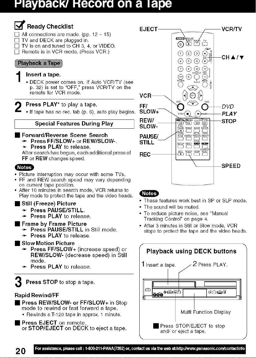
E_ Ready Checklist
[] All connections are made. (pp. 12, 15)
[] TV and DECK are plugged in.
[] TV is on and tuned to CH 3, 4, or VIDEO.
[] Remote is in VCR mode. (Press VCR.)
Insert a tape.
1
• DECK power comes on. If Auto VCR/TV (see
p. 32} is set to "OFF," press VCR/TV on the
remote for VCR mode.
CHA/T
Press PLAY* to play a tape.
• If tape has no rec. tab (p. 6), auto play begins.
Special Features During Play
• Forward/Reverse Scene Search
÷ Press FF/SLOW+ or REW/SLOW-.
_- Press PLAY to release.
After search has begun, each additional press of
FF or REW changes speed.
• Picture interruption may occur with some TVs.
• FF and REW search speed may vary depending
on current tape position.
• After 10 minutes in search mode, VCR returns to
Play mode to protectthe tape andthe video heads.
• Still (Freeze) Picture
-_ Press PAUSE/STILL
-_" Press PLAY to release.
• Frame by Frame Picture
-_ Press PAUSE/STILL in Still mode.
-_ Press PLAY to release.
• Slow Motion Picture
-_- Press FF/SLOW+ (increase speed) or
REW/SLOW- (decrease speed) in Still
mode.
Press PLAY to release.
Press STOP to stop a tape.
FF/
REW/
SLOW-
PAUSE/
STILL
O
• These features work best in SP or SLP mode.
• The sound will be muted.
• To reduce picture noise, see "Manual
Tracking Control" on page 4.
• After 3 minutes in Still or Slow mode, VCR
stops to protect the tape and the video heads.
Playback using DECK buttons
Insert a tipe. [,///- 2 Press PLAY.
Rapid Rewind/FF
• Press REW/SLOW- or FF/SLOW+ in Stop
mode to rewind or fast forward a tape.
• Rewinds aT-120 tape in approx. 1 minute.
• Press EJECT on remote,
or STOP/EJECT on DECK to eject a tape.
20
I Multi Function Display
• Press STOP/EJECT to stop
and/or eject a tape.

Insert a tape with a record tab (p. 6).
• DECK power comes on. If Auto VCR/TV (see p. 32)
is set to "OFF," press VCR/TV on the remote for
VCR mode.
Press CH AT, or NUMBER keys
to select the channel.
• If channel number is over 100, first press 100 key
then the other 2 digits.
• For "LINE" input, see p. 35.
Press SPEED
to select the record speed (p. 4).
SP = Standard Play
SLP = Super Long Play
• Speed appears on-screen and on Multi Function Display.
Press REC
to start recording.
(The VCR REC indicator lights up on Multi Function
Display),
• To edit out unwanted scenes, press PAUSE/STILL
to pause, and again to resume recording.
• You cannot view another channel during recording.
Press STOP
to stop recording.
• One Touch Recording (recording in progress),
-_ press REC repeatedly to set the recording length
(30 min. 4 hours) (see right).
• DECK shuts off after the preset record length.
• Record one station, watch another,
-_ press VCR/TV on the remote
(change to TV mode),
÷ select channels at TV (recording continues).
• Select Channels at DECK (In Stop or
Rec. Pause mode)
-_ press VCR/TV on the remote
(change to TV mode),
÷ select channels at DECK.
• Play a disc while recording a tape.
÷ insert a disc during recording,
÷ press DVD, and then press PLAY.
This video recorder, equipped with HQ
(High Quality) system, is compatible
with existing VHS equipment.
Only use tapes with the IVl:Eqmark. /
Only tapes tested and inspected for
use in 2, 4, 6, and 8 hour machines
are recommended.
0
Remove loose or peeling
labels from tapes to prevent
tape jam.
<One Touch Recording screen>
Record using DECK buttons
4 Press REC
to start
recording.
/
w
• It is not possible to record from DVD/CD to
VHS tape usinq DECK.
• Watching one channel and recording another
is not possible when using Cable Box or
DSS Receiver.
• After 5 minutes in Pause mode, DECK stops to
protect a tape and video heads.
2 Select I
Channel.
Multi Function Display
• Press STOP/EJECT to stop.
21
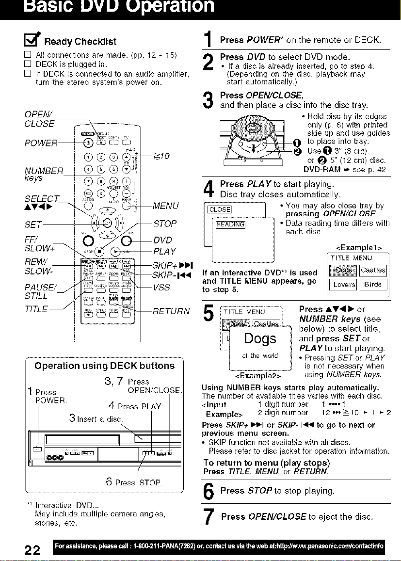
[_ Ready Checklist
[] All connections are made. (pp. 12, 15)
[] DECK is plugged in.
[] If DECK is connected to an audio amplifier,
turn the stereo system's power oil.
OPEN/
CLOSE
POWER
>10
@@@
_eUy_BER
SELECT
AV.9 •
SET
FF/
SLOW+_
REW/
SLOW-
PAUSE/j
STILL
TITLE _
[) [:) [[_
_OEQ_
Operation using DECK buttons
3, 7 Press
Press OPEN/CLOSE
POWER.
4 Press PLAY.
3 Insert a disc.
6 Press STOP.
*_Interactive DVD...
May include multiple camera angles,
stories, etc.
MENU
STOP
DVD
PLAY
_KIP+
SKIP- I_
VSS
RETURN
Press POWER* on the remote or DECK.
Press DVD to select DVD mode.
• If a disc is already inserted, go to step 4.
(Depending on the disc, playback may
start automatically.)
Press OPEN/CLOSE,
and then place a disc into the disc tray.
• Hold disc by its edges
only (p. 6) with printed
side up and use guides
to place into tray.
Use_) 3" (8 cm}
or _ 5" (12 cm} disc.
DVD-RAM .., see p. 42
Press PLAYto start playing.
Disc tray closes automatically.
pressing OPEN/CLOSE.
• Data reading time differs with
each disc.
_ • You may also close tray by
If an interactive DVD *_ is used
and TITLE MENU appears, go
to step 5.
f ..........................................
5 ;;TITLE MENU
ogs
I of the world
<Example2>
Using NUMBER keys starts play automatically.
The number of available titles varies with each disc.
<Input 1 digit number 1 •••• 1
Example> 2 digit number 12ooo-->10 * 1 * 2
Press SKIP+ IH_I or SKIP- I<< to go to next or
previous menu screen.
• SKIP function not available with all discs.
Please refer to disc jacket for operation information.
To return to menu (play stops)
Press TITLE, MENU, or RETURN.
Press AV<I • or
NUMBER keys (see
below) to select title,
and press SETor
PLAYto start playing.
• Pressing SETor PLAY
iS not necessary when
using NUMBER keys.
<Example1 >
TITLE MENU
Press STOPto stop playing.
Press OPEN/CLOSEto eject the disc.
22
 Loading...