

Panasonic PV310 Installation Manual

Before Reading This Manual
Thank you for purchasing the MICRO-IMAGECHECKER PV310.
In this manual, information on the hardware (installation, wiring, etc.) and the software (functions, setting
procedures, etc.) is described. Read this User’s Manual carefully before use.
Safety Precautions
To ensure that you use this product correctly, read this User’s Manual thoroughly before use. Make sure
that you fully understand the product and information on safe.
Conventions used in the Safety Precautions
Symbols:
The following symbols used in Safety Precautions.
Symbol Explanation:
WARNING
This indicates the existence of a hazard that could result in death of or serious damage to the operator, if
the safety instruction is not observed.
CAUTION
This indicates the existence of a hazard that could result in serious bodily injury or property damage, if
the safety instruction is not observed.
WARNING
• Use the product within its specified ratings and environmental conditions. Failure to do so might
result in abnormal heat and smoke coming from the product.
• Do not use the product in the environment where combustible gas presents. This might cause
explosion.
• Do not throw the product into fire. This might cause the batteries and electronic parts in the product
to explode.
CAUTION
• To prevent abnormal heat and smoke coming from the product, do not make the product operate up
to the limits of guaranteed features and performance.
• Never attempt to disassemble or alter the product. Failure to do so might result in abnormal heat and
smoke coming from the product.
• Do not touch the terminals while the power is ON. This might result in an electric shock.
• Surely connect the wires and connectors. Failure to do so might result in abnormal heat and smoke
coming from the product.
• Do not allow liquid, combustible materials or metallic objects to come into the product. Failure to do
so might result in abnormal heat and smoke coming from the product. Be sure to ground the product.
Failure to do so might result in an electric shock.
• Do not install (connect or disconnect) the product while the power is ON. This might result in an
electric shock.

Table of Contents
Precautions before Use............................................................... xi
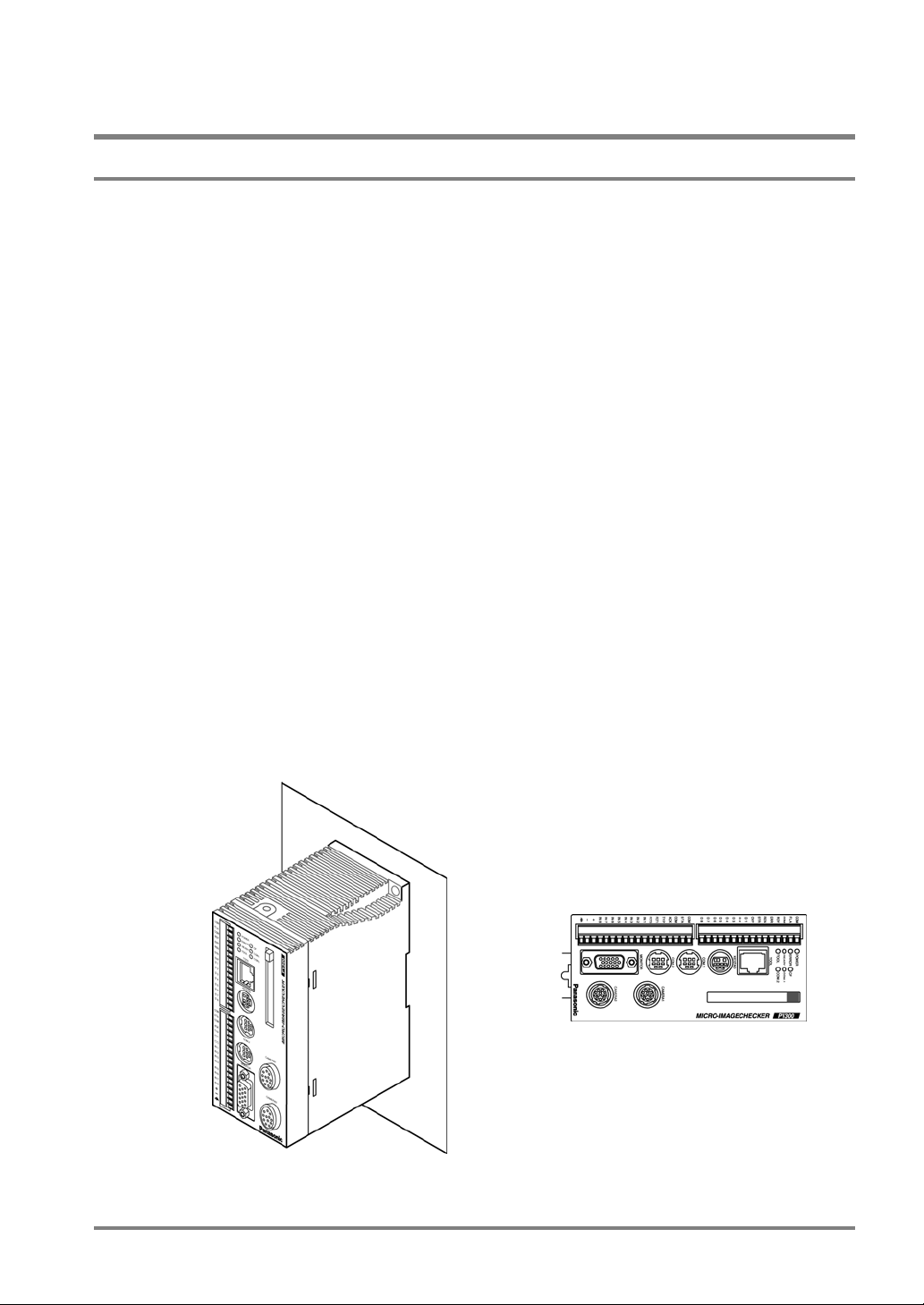
1. Names and Functions of Parts .............................................. 1
1.1 About the PV310 .......................................................................................... 2
1.2 Camera Peripherals...................................................................................... 4
1.2.1 Double Speed Random Camera: ANM831................................................ 4
1.2.2 Standard Camera: ANM832....................................................................... 5
1.2.3 Camera Cable/Camera Extension Cable................................................... 5
1.2.4 Camera Switching Unit: ANPV3700........................................................... 6
1.3 Keypad ......................................................................................................... 7
1.4 VGA Monitor ................................................................................................. 8
2. Installation and Wiring............................................................ 9
2.1 Connecting Peripherals .............................................................................. 10
2.2 Installation Environment and Mounting Space ........................................... 11
2.2.1 Installation Environment........................................................................... 11
2.2.2 Mounting the PV310................................................................................. 13
2.3 VGA Monitor Installation Environment........................................................ 14
2.3.1 Installation Environment........................................................................... 14
2.3.2 VGA Monitor Installation ..........................................................................15
2.3.3 VGA Monitor: Power Wiring ..................................................................... 16
2.4 Installing the Camera.................................................................................. 17
2.5 View Range - Lens Selection Table ........................................................... 18
2.5.1 Double Speed Random Camera: ANM831.............................................. 18
2.5.2 Standard Camera: ANM832..................................................................... 19
2.5.3 Notes on Mounting a Camera .................................................................. 21
3. Input and Output Interface Ports ......................................... 23
3.1 Parallel Ports .............................................................................................. 24
3.1.1 Wiring to the Terminal Blocks ..................................................................24
3.1.2 Pin Assignments....................................................................................... 25
3.1.3 Notes on Power Supply and Wiring .........................................................26
3.1.4 About Grounding ...................................................................................... 27
3.1.5 Arrangements of the Output Terminals and Output Circuit...................... 28
i

3.1.6 Arrangements of Input Terminals and Input Circuit .................................30
3.1.7 FLASH Output Synchronizing Signal ....................................................... 32
3.2 About RS-232C Port ...................................................................................34
3.2.1 Port Used for RS-232C Communication .................................................. 34
3.2.2 Pin Assignments of COM1 Port And Example of Connections to External
Device ......................................................................................................35
3.3 About Ethernet Port.....................................................................................39
3.3.1 Port Used for Ethernet Communication ...................................................39
3.3.2 Pin Assignments of TOOL Port and Example of Connection with PC .....40
3.3.3 Vision Support Tool AXTOOL Ver. 3........................................................ 41
4. Basic Operation .....................................................................43
4.1 About Screen Monitor .................................................................................44
4.2 RUN and SETUP Modes.............................................................................45
4.2.1 About SETUP and RUN Modes ...............................................................45
4.2.2 Switching between RUN Mode and SETUP Mode .................................. 45
4.3 How To Preprocess and Display Images ....................................................46
4.4 Basic Operation Using the Keypad .............................................................47
4.4.1 Selecting an Option from the Menu..........................................................47
4.4.2 Setting (Inputting) Values......................................................................... 47
4.4.3 Setting the Inspection Area ......................................................................48
4.5 Temporarily Switching the Display Camera Images....................................51
4.5.1 Display Images......................................................................................... 51
4.5.2 Selecting a Display Camera Image Using the Display Camera Image
Function.................................................................................................... 51
4.5.3 Selecting a Display Gray Value/Binary Using the Display Gray Value/Binary
Function.................................................................................................... 52
5. Procedure for Setting Inspection Conditions .....................53
5.1 Setting Inspection Conditions......................................................................54
5.2 Selecting a Camera Mode...........................................................................55
5.3 Setting a Shutter Speed ..............................................................................57
5.4 Selecting a Product Type ............................................................................58
5.4.1 Selecting a Product Type .........................................................................58
5.4.2 Copying an Existing Product Type ...........................................................59
5.4.3 Deleting a Product Type...........................................................................59
5.4.4 Deleting All Product Types ....................................................................... 60
ii

5.4.5 Entering a Product Type Title................................................................... 60
5.5 Importing Images into a Memory ................................................................ 61
5.6 Inspection Overview ................................................................................... 62
5.7 Storing Setting (Revised) Data in the PV310 ............................................. 63
5.8 Executing Inspection .................................................................................. 64
5.8.1 Procedure for Inspection Execution ......................................................... 64
5.8.2 Process Sequence for Executing Inspection ...........................................65
6. Setting Checkers................................................................... 67
6.1 What Is a Checker? .................................................................................... 68
6.1.1 Types and Overview of Checkers ............................................................ 68
6.1.2 Basic Settings of Checkers ......................................................................70
6.1.3 Basic Procedure for Setting Checkers ..................................................... 70
6.1.4 Selecting a Checker Number and a Checker Type..................................71
6.1.5 Selecting a Camera Image....................................................................... 73
6.1.6 Preprocessing Settings ............................................................................74
6.1.7 Setting a Slice Level................................................................................. 78
6.1.8 Setting a (Mask) Area ..............................................................................80
6.1.9 Area Size Adjustment Function................................................................ 83
6.2 Convenient Functions for Setting a Checker .............................................. 88
6.2.1 Changing the Menu Window to a Translucent Color ...............................88
6.2.2 Temporarily Hiding the Menu Window ..................................................... 89
6.3 Binary Window............................................................................................ 90
6.3.1 Menu Options........................................................................................... 90
6.3.2 What Is Binary Window? ..........................................................................90
6.3.3 Setting Procedure ....................................................................................91
6.4 Gray Window .............................................................................................. 92
6.4.1 Menu Options........................................................................................... 92
6.4.2 What Is Gray Window? ............................................................................92
6.4.3 Setting Procedure ....................................................................................93
6.5 Binary Edge ................................................................................................ 94
6.5.1 Menu Options........................................................................................... 94
6.5.2 What Is Binary Edge? ..............................................................................94
6.5.3 Setting Procedure ....................................................................................95
6.6 Gray Edge .................................................................................................. 98
6.6.1 Menu Options........................................................................................... 98
iii

6.6.2 What Is Gray Edge? .................................................................................99
6.6.3 Setting Procedure...................................................................................100
6.7 Feature Extraction.....................................................................................105
6.7.1 Menu Options .........................................................................................105
6.7.2 What Is Feature Extraction?................................................................... 106
6.7.3 Setting Procedure...................................................................................108
6.8 Smart Matching .........................................................................................112
6.8.1 Menu Options .........................................................................................112
6.8.2 What Is Smart Matching? ....................................................................... 113
6.8.3 Setting Procedure...................................................................................114
6.9 Contour Matching......................................................................................124
6.9.1 Menu Options .........................................................................................124
6.9.2 What Is Contour Matching?.................................................................... 124
6.9.3 Setting Procedure...................................................................................125
6.10 Flaw Detection ........................................................................................128
6.10.1 Menu Options.........................................................................................128
6.10.2 What Is Flaw Detection? ........................................................................129
6.10.3 Setting Procedure...................................................................................132
6.11 Position Adjustment ................................................................................139
6.11.1 Overview.................................................................................................139
6.11.2 Refering to Position Adjustment Amount Using Checkers.....................140
6.12 Position Adjustment (Binary Edge)..........................................................141
6.12.1 Setting Procedure...................................................................................141
6.12.2 Saving a Base Position ..........................................................................142
6.12.3 What To Do If You Faced a Trouble ......................................................142
6.13 Position Adjustment (Gray Edge)............................................................143
6.13.1 Setting Procedure...................................................................................143
6.13.2 Saving a Base Position ..........................................................................144
6.13.3 What To Do If You Faced a Trouble ......................................................145
6.14 Position Adjustment (Feature Extraction)................................................146
6.14.1 Setting Procedure...................................................................................146
6.14.2 Saving a Base Position ..........................................................................147
6.14.3 What To Do If You Faced a Trouble ......................................................147
6.15 Position Adjustment (Matching)...............................................................148
6.15.1 Setting Procedure...................................................................................148
6.15.2 Saving a Base Position ..........................................................................148
iv

6.15.3 What To Do If You Faced a Trouble ......................................................149
6.16 Rotation Adjustment ............................................................................... 150
6.16.1 Overview ................................................................................................ 150
6.16.2 How Checkers Refer to Adjustment Amount .........................................151
6.17 Rotation Adjustment (Binary Edge Horiz., Binary Edge Vert.)................ 152
6.17.1 Setting Procedure .................................................................................. 152
6.17.2 Saving a Base Position ..........................................................................153
6.17.3 What To Do If You Faced a Trouble ......................................................153
6.18 Rotation Adjustment (Gray Edge Horiz., Gray Edge Vert.)..................... 154
6.18.1 Setting Procedure .................................................................................. 154
6.18.2 Saving a Base Position ..........................................................................155
6.18.3 What To Do If You Faced a Trouble ......................................................155
6.19 Rotation Adjustment (Feature Extraction) .............................................. 156
6.19.1 Setting Procedure .................................................................................. 156
6.19.2 Saving a Base Position ..........................................................................157
6.19.3 What To Do If You Faced a Trouble ......................................................157
6.20 Rotation Adjustment (360 Degree Detection)......................................... 158
6.20.1 Setting Procedure .................................................................................. 158
6.20.2 Saving a Base Position ..........................................................................158
6.20.3 What To Do If You Faced a Trouble ......................................................159
6.21 Rotation Adjustment: Matching............................................................... 160
6.21.1 Setting Procedure .................................................................................. 160
6.21.2 Saving a Base Position ..........................................................................160
6.21.3 What To Do If You Faced a Trouble ......................................................161
6.22 Rotation Adjustment (Contour) ............................................................... 162
6.22.1 Setting Procedure .................................................................................. 162
6.22.2 Saving a Base Position ..........................................................................162
6.22.3 What To Do If You Faced a Trouble ......................................................163
7. Calculation, Analysis and Output of Inspection Results. 165
7.1 Overview................................................................................................... 166
7.1.1 Calculation, Analysis, and Display of the Inspection Result Data.......... 166
7.1.2 Outputting Data to the External Device.................................................. 166
7.2 Numeric Calculation (CA01 to CA99) ....................................................... 167
7.2.1 Main Functions....................................................................................... 167
7.2.2 Reference Data and Calculation Functions ...........................................167
v

7.2.3 Creating a Numeric Calaulation ............................................................. 171
7.2.4 Specifying the Judge. Max./Min. Values- Judging the Calculation Results
................................................................................................................173
7.2.5 Copying a Numeric Calculation.............................................................. 173
7.2.6 Deleting a Numeric Calculation.............................................................. 174
7.2.7 Projection Distance ................................................................................175
7.2.8 Conversion of Length L into Actual Size Value: Conversion Data.........176
7.2.9 Restrictions on Numeric Calculation Function .......................................179
7.2.10 Error Messages Displayed When You Set Numeric Calculation Formula
................................................................................................................181
7.3 Judgment (JD01 to JD96) .........................................................................182
7.3.1 Main Functions .......................................................................................182
7.3.2 Reference Data and Operators ..............................................................182
7.3.3 Creating a Judgment Formula................................................................ 184
7.3.4 Saving Total Judgments......................................................................... 185
7.3.5 Saving a Conditional Formula for Save Image.......................................186
7.3.6 Restrictions on Judgment.......................................................................188
7.3.7 Error Messages Displayed When You Set a Judgment Formula...........188
7.4 Statistics (QS01 to QS96) .........................................................................189
7.4.1 Main Functions .......................................................................................189
7.4.2 Reference Data ...................................................................................... 189
7.4.3 Statistics Items .......................................................................................190
7.4.4 Referring Statistic Object Data............................................................... 190
7.4.5 Deleting the Data Referred to Statistics .................................................191
7.4.6 Resetting the Counted Results ..............................................................192
7.5 Data Monitor..............................................................................................193
7.5.1 Main Functions .......................................................................................193
7.5.2 Data Can Be Displayed in the Data Monitor Table ................................ 194
7.5.3 Referring the Data to Data Monitor Table ..............................................194
7.5.4 Saving the Fixed Name (Title) to the Cell ..............................................196
7.5.5 Changing the Number of Rows and Columns in the Data Monitor Table196
7.5.6 Selecting the Alignment of the Data Monintor........................................ 198
7.5.7 Changing Max. / Min. Values in RUN Mode...........................................199
8. TOOL.....................................................................................201
8.1 TOOL ........................................................................................................202
8.2 Drawing an Image on the Monitor Screen: Marker Function.....................203
8.2.1 Creating a New Marker ..........................................................................203
vi

8.2.2 Copying an Existing Marker ................................................................... 204
8.2.3 Deleting a Marker................................................................................... 204
8.3 Reference Point........................................................................................ 205
8.4 Group Move.............................................................................................. 206
8.5 Displaying the Settings in RUN Mode ...................................................... 207
8.5.1 Selecting an Display Image.................................................................... 208
8.5.2 Displaying a Checker Shape, Marker and Reference Point and Data
Monitor ...................................................................................................210
8.6 Execution Modes ...................................................................................... 211
8.6.1 Overview ................................................................................................211
8.6.2 Setting to Execution Mode ..................................................................... 212
8.6.3 “Execute All” Execution Mode................................................................ 213
8.6.4 “Automatic Switch” Execution Mode ...................................................... 214
8.6.5 “User-Defined” Execution Mode............................................................. 216
9. Environment Settings ......................................................... 218
9.1 What Are Environment Settings? ............................................................. 219
9.2 Initial Settings ........................................................................................... 223
9.2.1 A list of Initialization Menu Options ........................................................ 223
9.2.2 Protecting the Setting Data Using a Password ...................................... 224
9.3 Saving Images.......................................................................................... 226
9.3.1 What Is Image Save?............................................................................. 226
9.3.2 Saving Images Using the Keypad.......................................................... 227
9.3.3 Saving an Image per Inspection.............................................................228
9.3.4 Saving the Images of Which the Conditional Formula Was Judged as NG
............................................................................................................... 228
9.3.5 Selecting Operation When the Number of Saved Images Reached 16 pairs
............................................................................................................... 229
9.3.6 Performing Inspection While Only Saved Image Is Displayd (Display a Save
Image) .................................................................................................... 230
9.3.7 Running a Test Using a Saved Image ................................................... 231
9.3.8 Outputting a Save Image to the External Device (Backing up to Memory
Card) ......................................................................................................232
9.3.9 Erasing All the Saved Image.................................................................. 232
9.4 Outputting Images .................................................................................... 233
9.4.1 What Is Image Outputting? ....................................................................233
9.4.2 Outputting the Images to a Compact Flash Card................................... 234
9.4.3 Outputting the Images to PC (support in the near future)...................... 236
vii

9.5 Re-Registering the Template ....................................................................237
9.5.1 Re-Registering Mode and Diplay Options..............................................237
9.5.2 Setting Procedure...................................................................................237
9.6 Initializing Environment Settings ...............................................................238
10. Parallel Communication ....................................................239
10.1 Communications via Parallel Port ...........................................................240
10.1.1 Input from the External Device............................................................... 240
10.1.2 The Data Output from the PV310........................................................... 240
10.1.3 Data Assignment for Hanshake .............................................................242
10.2 Input/Output Timing According to Start Settings .....................................243
10.2.1 Starting Inspection - Once......................................................................243
10.2.2 Starting Inspection - Repeat...................................................................244
10.3 Input/Output Timing According to Handshake Settings...........................245
10.3.1 When the Handshake Function Is Set To “None” ..................................245
10.3.2 When the Handshake Function Is Set Not To “Yes”..............................246
10.4 Data Switch Timing According to Data Reset Conditions .......................247
10.4.1 Reset Condition: Hold ............................................................................247
10.4.2 Reset Condition: Output Off after Image Capture.................................. 248
10.4.3 Reset Condition: Output Off before Image Capture............................... 248
10.5 Switching Data Using External Signals ...................................................249
10.5.1 Switching the Product Types..................................................................249
10.5.2 Switching the Display Camera Images .................................................. 251
10.5.3 Re-registering the Template...................................................................252
10.5.4 Restoring the Setting Data Stored in CF Card....................................... 255
11. RS-232C Communication ..................................................257
11.1 Overview .................................................................................................258
11.2 Serial (Per Start)/Serial (Async.) .............................................................259
11.2.1 Selecting and Setting the Output Data to the External Device ..............259
11.2.2 Formats of the Commands from the External Device ............................259
11.2.3 Setting COM Port ...................................................................................260
11.2.4 Output Data ............................................................................................260
11.2.5 A List of Commands...............................................................................262
11.2.6 Details of Commands.............................................................................263
11.3 Computer Link.........................................................................................283
11.3.1 Overview and Communication Specifications........................................283
viii

11.3.2 Setting a Computer Link Communication .............................................. 286
11.3.3 Setting Output Conditions ...................................................................... 287
11.3.4 Configuring the COM Port...................................................................... 288
12. Ethernet Communication.................................................. 289
12.1 Overview and Ethernet Outputs ............................................................. 290
12.1.1 Overview ................................................................................................ 290
12.1.2 Selecting an Output Procedure and Output Data .................................. 291
12.2 Communication Methods........................................................................ 292
12.2.1 Communicating between one PV310 and one Computer...................... 292
12.2.2 Communicating between a Computer and Multiple PV310s .................293
13. Using a Compact Flash Card............................................ 295
13.1 Storing Data in a Compact Flash Card................................................... 296
13.2 Inserting and Removing the Memory Card............................................. 297
13.2.1 Inserting the Memory Card.....................................................................297
13.2.2 Removing the Memory Card.................................................................. 297
13.3 Backing up and Restoring Setting Data and Images.............................. 298
13.3.1 Backing up and Restoring the Setting Data........................................... 298
13.3.2 Backing up and Restoring the Memory Images .....................................299
13.3.3 Backing up and Restoring the Saved Images........................................ 301
13.4 Copying the Screen Display ................................................................... 303
13.5 Outputting the Inspection Results to a CF Card ..................................... 304
13.6 Using a Folder Tree................................................................................ 305
14. Information on the PV310 and Help Function Settings.. 307
14.1 Information on the PV310....................................................................... 308
14.1.1 Options of the INFO. Menu .................................................................... 308
14.1.2 Checking Remaining Storage Capacity of Memory............................... 308
Setting Date and Time Using the Calendar Feature.......................................... 309
14.1.3 Setting IP Address .................................................................................310
14.1.4 Version Information................................................................................ 310
14.2 Setting Help ............................................................................................ 311
14.2.1 Making Light Adjutments........................................................................ 311
14.2.2 Making Focal and Aperture Adjustments ...............................................312
14.2.3 Displaying an Image Profile ...................................................................313
14.2.4 Checking Connections Using I/O Monitor.............................................. 314
ix

15. Troubleshooting.................................................................315
15.1 ERROR (Error) Signal Is Output .............................................................316
15.2 Error Code Number Is Displayed in SETUP Mode..................................317
16. Camera Switching Unit ......................................................319
16.1 Overview .................................................................................................320
16.2 Functions and Settings............................................................................321
16.3 Remote Switching Signal ........................................................................322
17. General Specifications ......................................................323
18. Product Numbers ...............................................................329
19. Dimensions.........................................................................335
20. Appendix.............................................................................341
20.1 Pin Assignment of a Double Speed Random Camera (ANM831)...........342
20.2 Pin Assignment of a Standard Camera (ANM832)..................................343
Record of Changes ...................................................................344
x

Precautions before Use
Installation Environment
Avoid installing the PV310 in the following locations:
• Locations with direct sunlight or environmental temperatures that exceed a range between 0°C and
50 °C (a range of 0 to 40 °C for VGA monitor).
• Locations with a relative humidity exceeding a range of 35%RH to 75%RH (a range of 20%RH to
85%RH for VGA monitor) or with a condensing due to a sharp temperature change.
• Locations with an atmosphere containing corrosive gases or flammable gases.
• Locations subject to the main unit to direct vibration or impact.
• Locations with a lot of fine particles, iron filings or salt.
• Locations where the product can become wet with water, oil or chemicals.
• Locations with an atmosphere likely to contain organic solvents (such as benzene, paint thinner, and
alcohol) or strongly alkaline materials (such as ammonia and caustic soda).
Static Electricity
• In dry environment, there is a risk of generation of static electricity of extremely high voltage, so when
there is a need to touch the product, you should always discharge the accumulated static electricity
through your body by touching a grounded metal surface.
Cleaning
• Never use thinners or similar solvents, as they may dissolve the board and cause colors to run.
Power Supply Unit and Power Sequence
• Use an insulated power supply unit with a built-in protection circuit. The PV310 power supply unit is a
non-insulated circuit. Therefore, applying an abnormal voltage might damage the internal circuit. If
you use a power supply unit without a protection circuit, supply power through a protective device
such as a fuse.
• Consider the power supply sequence so that the power supply unit for the PV310 can be turned off
before the one for the input/output is turned off.
• If you turn the input/output power off before turning the PV310 off, the PV310 will detect a change in
the input signal level and may malfunction.
Before Turning on the PV310
Pay attentions to the followings when turning on the PV310 for the first time;
• Confirm no wiring waste or especially any conductive substance is on the printed circuit board.
• Confirm that the power wiring, input/output wiring and power supply voltage are correct.
• Confirm that the fixing and terminal screws are securely tightened.
xi

General Cautions
• Use the monitor, monitor cable, keypad, camera and camera cables of serial numbers specified by
Matsushita Electric Works, Ltd. A breakdown, damage or destruction by using any other than the
specified will not be covered by our guarantee.
• Do not disassemble, remodel the PV310 or change its internal settings. A breakdown, damage or
destruction by disassembling, remodeling the PV310 or not following the instruction described in the
manuals will not be covered by our guarantee.
• Do not change or set items that should not be as described in the manuals or the specifications.
Breakdown, damage or destruction resulting from changing or setting them will not be covered by our
guarantee.
• When all PV310 settings are complete, disconnect the keypad and the computer used for backing up
or restoring data from the PV310 in order to prevent a malfunction or an operation mistake due to
noises.
• Do not perform the insulation resistance or withstand voltage test between the power source or
input/output signals and the metallic part of connectors or camera cases.
To USA Customer
Products sold by Seller are covered by the warranty and patent indemnification provisions in its Terms
and Conditions of Sale only.
xii

Chapter 1
Names and Functions of Parts
1
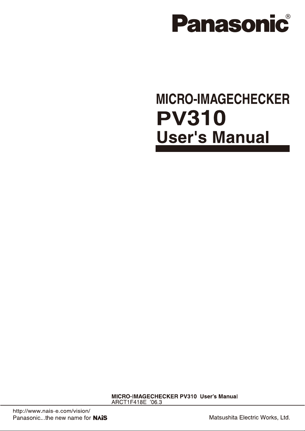
1.1 About the PV310
Designations and Descriptions of Each Part
No. Designation Description
1 External output terminal
(16 pins)
2 External input terminal (15
pins)
3 Power terminal Acceptable input voltage is 24V DC. The power terminal is located on the
4 Operating LEDs Indicate the operating status of the PV310.
5 Memory card slot Supports for a FAT16- formatted Compact Flash card (Max. 512MB )
6 TOOL port (Ethernet Port) Connects to the external device via Ethernet port. Use a cross cable
7 KEYPAD connector Connects to the operation keypad.
8 COM port (RS-232C port) Connects to the external device via the COM port. COM2 is not available.
9 Camera connectors Can connect to up to two cameras: CAMERA 1 and CAMERA 2. Using a
10 MONITOR Connects to the VGA monitor
11 DIN rail attachment lever
(for hooking with
one-touch operation)
An external output terminal block (by Phoenix), product #: 1840502.
An external input terminal. COMMON terminal is for +/-. An external
output terminal block (by Phoenix), product #: 1840528.
input terminal block.
• POWER (green):
The green POWER LED lights when the PV310 is being energized.
• ERROR (red):
The red ERROR LED lights when an error is detected.
• READY (green):
The green READY LED lights when the PV310 is ready to receive the
signals including start signal from the external device
• CF: The green CF LED lights when the PV310 is accessing the
memory card.
• COM1: The green COM1 LED lights when serial communication is
established.
when connecting between an external device and a PV310.
camera switching unit enables you to connect to maximum four standard
cameras.
Offers quick and easy mounting of the PV310 onto the DIN rail.
2

No. Designation Description
12 Backup battery This is a battery for retaining information about calendar in the PV310. If
the backup battery runs out, the screen monitor displays “Battery used
up!”. In such a case, replace with a new backup battery. Product number:
AFPG804 (Service life: About 10 years at 25°C)
Connect only the designated products to the PV310.
3
1.2 Camera Peripherals
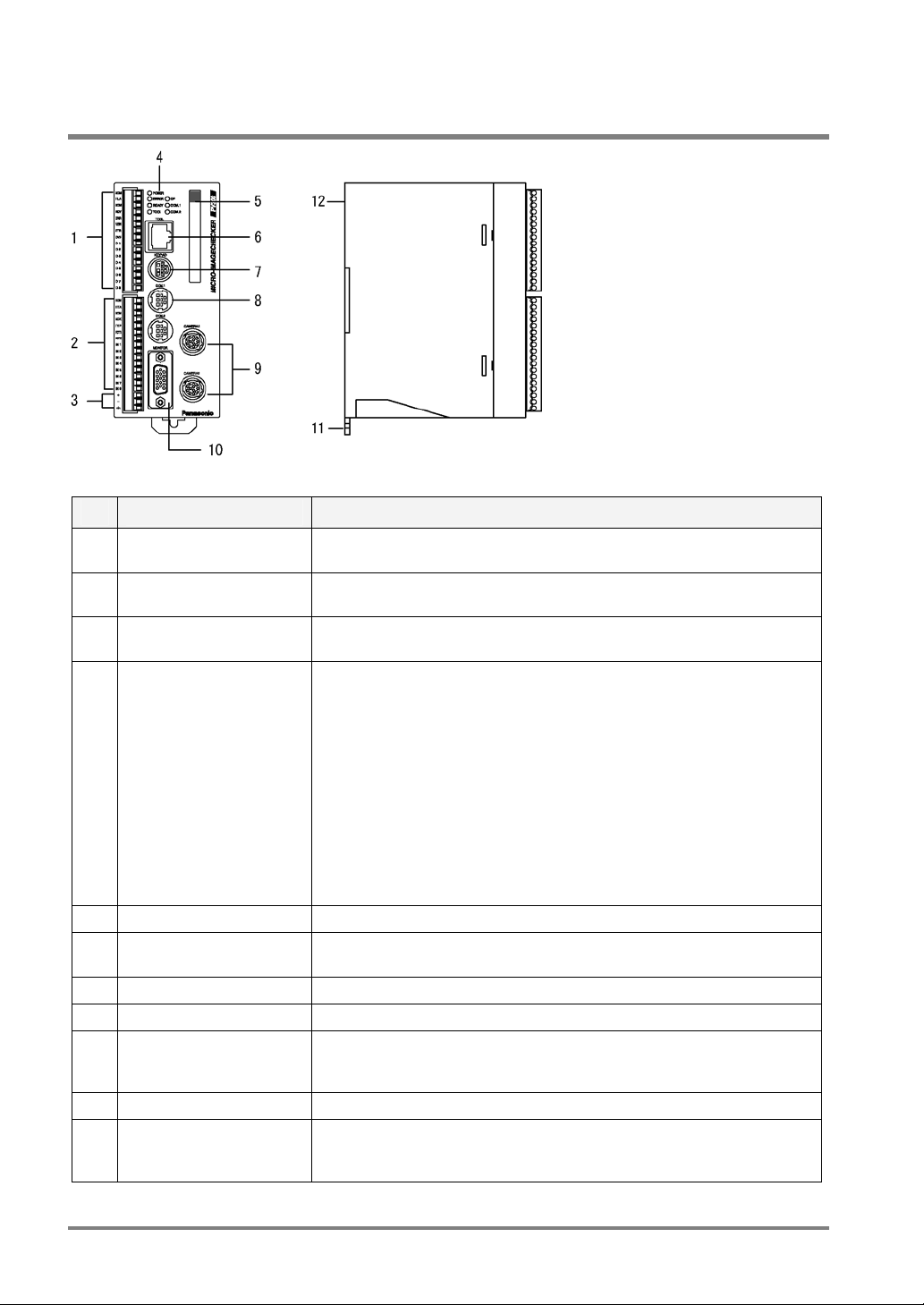
1.2.1 Double Speed Random Camera: ANM831
Names and the Description
No. Name Description
1 Camera Refers to the camera body.
2 Lens mount C-mount.
3 Lens Use the C-mount lens together with an adapter ring as necessary. Refer to
4 Cable connector Connects to the controller with a camera cable. (ANM84303**)
5 VOL knob for fine
adjustment of gain
6 DIP-SW Switches camera modes or adjusts camera gain
7 Holding fixture Mounts the camera
page 18 for selecting view range and lens.
Makes a fine adjustment for camera gain
If you turned this knob clockwise when the DIP SW 5 is in the ON position,
the image to be captured becomes brighter.
Positions of DIP Switches and VOL knob
No. Description
1-4
5 Gain fine
6 Camera
7-8 Always leave OFF.
*Default settings: DIP SW 5: ON, the rest of the dip switches: OFF, VOL knob: +10 dB
Always leave OFF
adjustment
mode
switching
ON: Allows you to make fine adjustment
within the range between 0 and +10dB
using the VOL knob
OFF: 0dB
ON: D.S. Random Frame mode
OFF: D.S. Random Field mode (default)
• Do not connect different types of cameras to the controller.
• Use the CAMERA 1 port when connecting just one camera to the controller.
• Use only the designated camera cable or camera extension cable.
• Use the specified camera (extension) cable.
• Do not connect multiple cables to extend the camera cable and camera extension cable.
• Do not touch the CCD element or the lens surface of the camera. Attach the lens cap to
keep off dust when not in use.
• Switch the dip switches in accordance with your camera mode.
• Leave the dip switches 1, 2, 3, 4, 7, and 8 OFF (default).
4
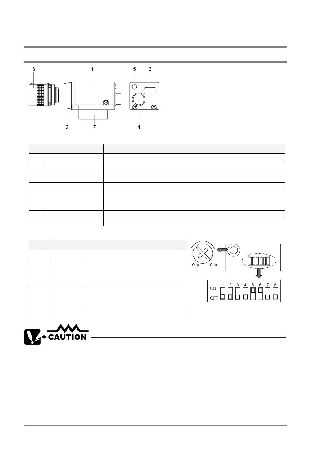
1.2.2 Standard Camera: ANM832
Part Names and the Descriptions
No
Part name Description
.
1 Camera The camera main unit.
2 Lens fixture CS-mount
3 Lens Use the C/CS-mount lens together with an adapter ring as necessary.
4 Connector Connects to the controller. Use a designated camera extension cable.
5 Holding fixture To mount the camera
• Do not connect different types of cameras to the controller.
• Use the CAMERA 1 port when connecting just one camera to the controller.
• Use only the designated camera cable or camera extension cable.
• Do not connect multiple cables to extend the camera cable and the camera extension cable.
• Do not touch the CCD element or the lens surface of the camera. Attach the lens cap to
keep off dust when not in use.
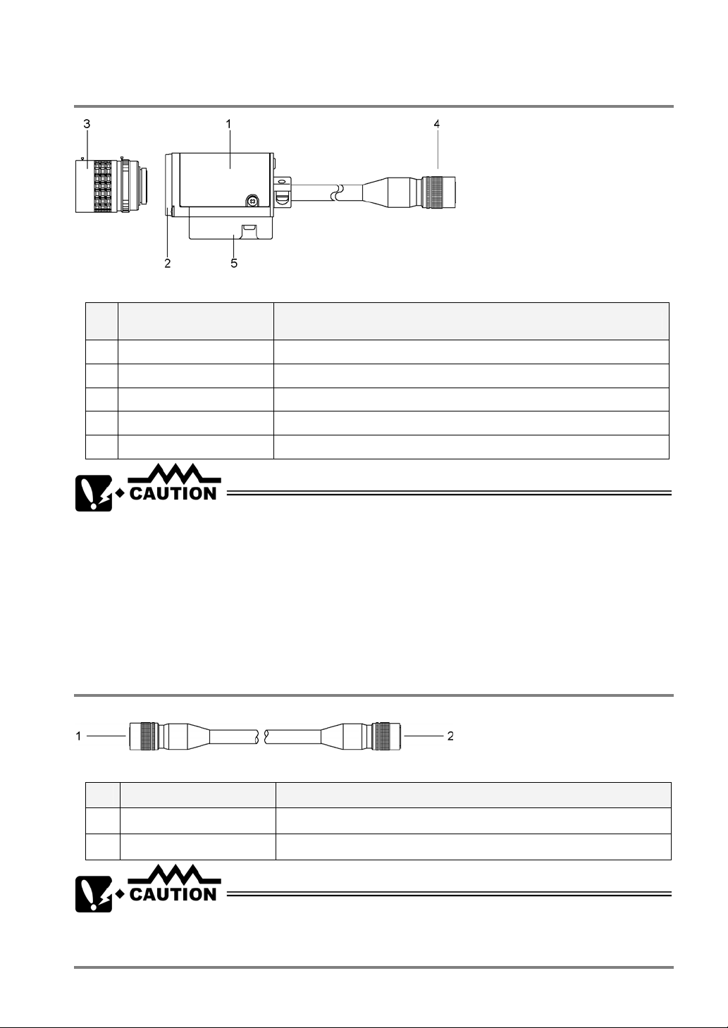
1.2.3 Camera Cable/Camera Extension Cable
Part Names and the Descriptions
No. Part name Description
1 Connector (round, male) Connects the male connector to the controller
2 Connector (round, female) Connects the female connector to the camera
• Use only the designated camera cable.
• Do not bend the camera cable forcibly or apply load to the connector joints.
5
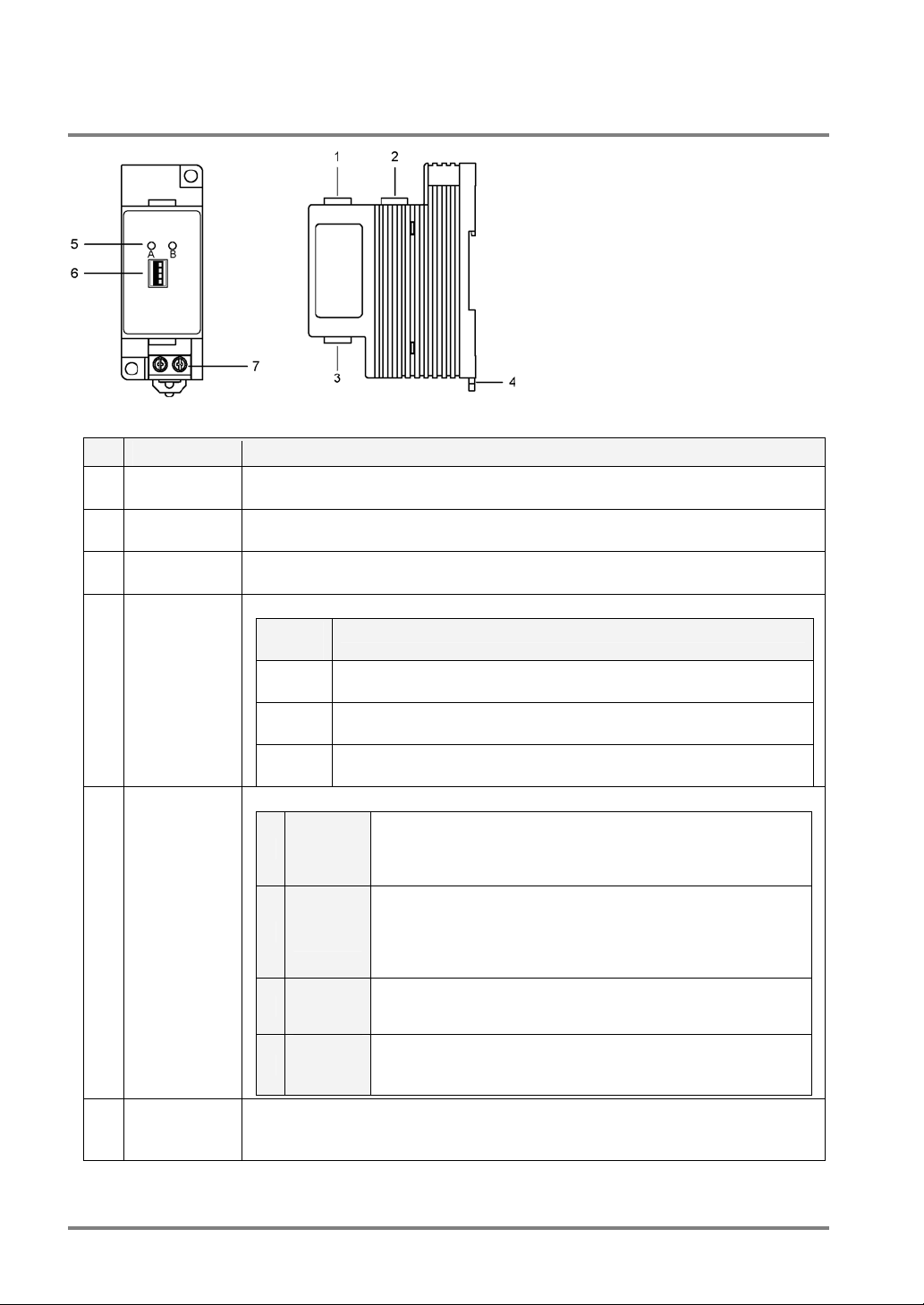
1.2.4 Camera Switching Unit: ANPV3700
Designations and Descriptions of Each Part
No Name Description
Input port for
1
Camera A
Input port for
2
Camera B
OUT (image
3
output) port
Camera
4
A/Camera B
indicators
Dip switches
5
(4)
6 Input terminal
for external
signal
*The division mode is available only in a standard camera ANM832 (ANM832CE). A double speed random
camera ANM831 is not available if it is in the division mode.
Connects a camera. Camera A is connected to this port.
Connects a camera. Camera B is connected to this port.
Outputs images to the PV310. Use the provided cable for switching cameras.
The indicators tell which camera is in use for capturing images.
Lighting
Lamp
A only The PV310 is in camera switching mode (the dip switch 2 is placed in
B only The PV310 is in camera switching mode (the dip switch 2 is placed in
A and B The PV310 is in DIV mode (the dip switch 2 is placed in the DIV
The four dip switches change the functions shown in the table below.
1
2
3 A / B
4
This is a terminal for switching cameras in DIV mode.
Status
the NORMAL position). The image captured by Camera A is output.
the NORMAL position.) The image captured by Camera B is output.
position).
If you want to switch between Camera A and Camera B using
LOCAL /
REMOTE
NORMAL
/ DIV*
Upper/
Lower
division
an external device when the PV310 is in camera switching
mode (the dip switch 2 is placed in the NORMAL position), set
to “REMOTE”.
If you want to switch between Camera A and Camera B (in
camera switching mode), set to “NORMAL”. If you want to
combine the upper and lower half parts of two images captured
by Camera A and Camera B in one image (in the DIV mode),
set to “DIV”.
This is a switch for changing the cameras to output the images
in camera switching mode (the dip switch 1 and 2 are placed in
LOCAL and NORMAL positions respectively).
In camera division mode (the dip switch 2 is placed in the DIV
position), select a part of the images captured by Camera A
and Camera B that you want, upper half or lower half.
6
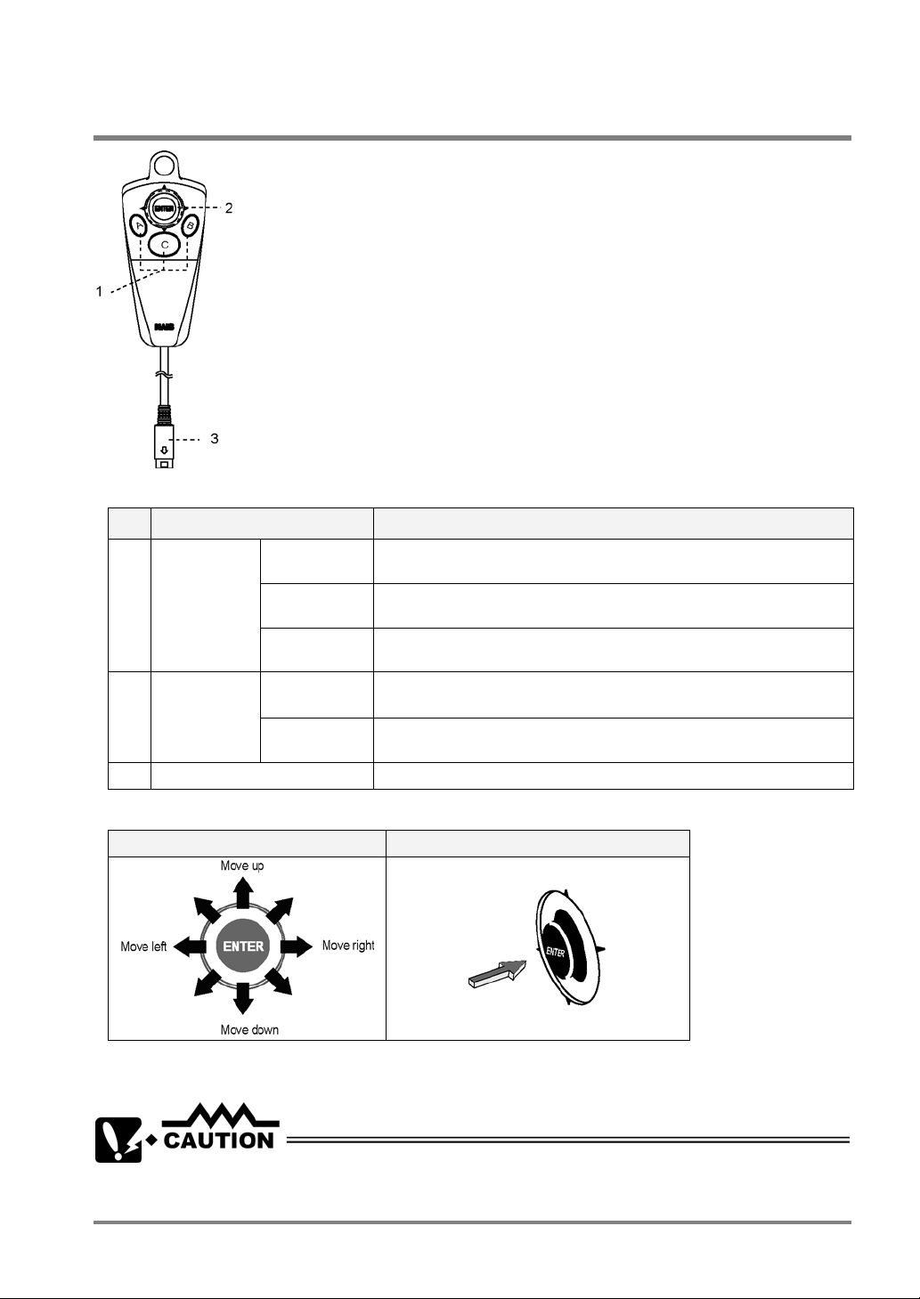
1.3 Keypad
Names and the Descriptions
No. Description Details
1 A, B, C keys
2 ENTER key
3 Connector Connects the keypad to the PV310.
A key Starts an inspection. Performs a test in SETUP mode. Executes
B key Displays a sub-menu for each menu. Press and hold down this key for
C key Switches between SETUP mode and RUN mode. Goes back to the
Cursor
Operation
Confirmation
Operation
inspection in RUN mode.
more than one second to save the screen copy on the memory card.
previous hierarchy or close the window.
Moves the cursor in the up to 8 directions.
Use this lever to select the menu and move the start and end points.
Executes (or Determines) the selected option.
Cursor Operation and Determination Operation with the Cursor Lever
Cursor operation Determination (ENTER) key operation
If you try to move the cursor while pressing and holding down the ENTER key, the highlighted option may be
determined. Release and move the ENETER key when you move the cursor.
Connect only the designated keypad (ANM852**) to the PV310.
7
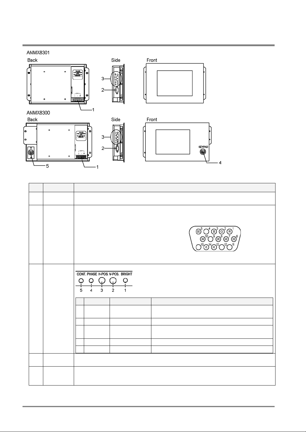
1.4 VGA Monitor
Part Names and the Descriptions
No. Part name Description
1 Power
connector
2 RGB input
connector
3 Adjustment
volume
Acceptable input voltage: 24V DC
A connector for RGB input. Connects to the monitor with the VGA monitor cable
-ANMX8331*. (Connector: Mini D-sub, 15 pins, female)
• 1 - R: Red image signal
• 2 - G: Green image signal
• 3 - B: Blue image signal
• 5, 6, 7, 8, and 10 - GND: Signal ground
• 13 - HS: Horizontal synchronizing signal
• 14 - VS: Vertical synchronizing signal.
The following adjustments are available
100%)
Adjusts the screen horizontal position (per 16 pixels).
4 Keypad
connector
5 Keypad
cable
connector
# Indication Name Function
1 BRIGHT Brightness Adjusts the brightness. (Brightness: approx. 20 to
2 V-POS. Vertical Position Adjusts the screen vertical position (per 16 lines).
3 H-POS. Horizontal
Position
4 PHASE Phase Adjusts the screen flickering.
5 CONT. Contrast Adjusts the contrast.
Connects the keypad (ANM852**). However, the keypad connector is available only if the
monitor is connected to the PV310 with the keypad cable.
Connects the keypad link cable (ANMX8333). (Connect one end of the cable to the
PV310). Use the connector in order to connect the keypad to the monitor front.
Caution: Check for proper connections before turning the PV310 on.
8

Chapter 2
Installation and Wiring
9
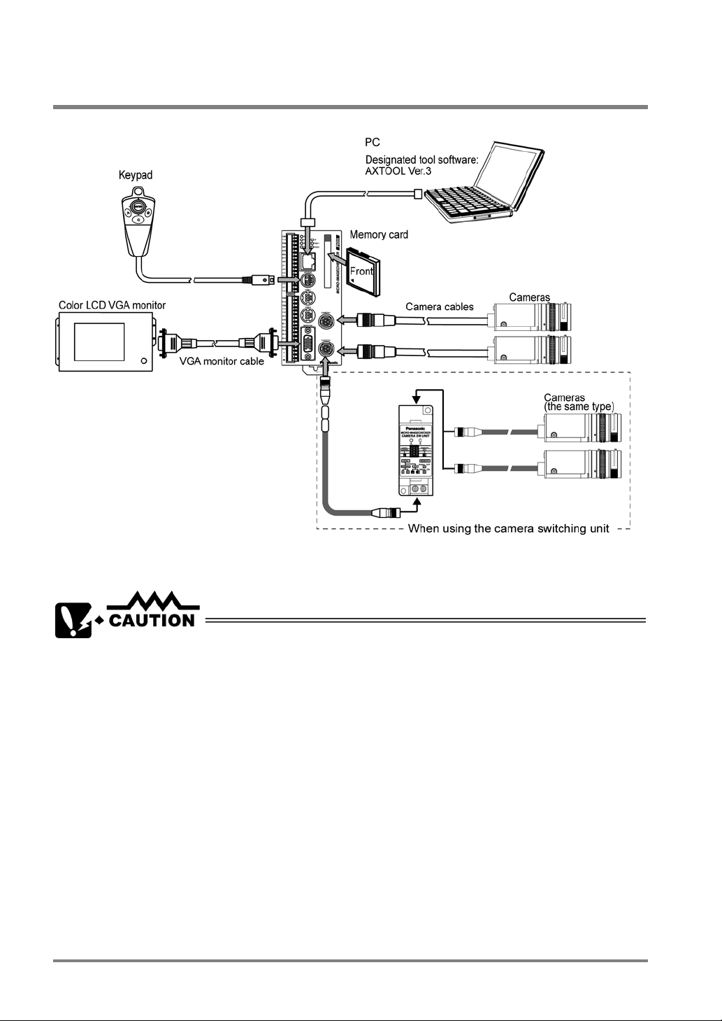
2.1 Connecting Peripherals
Be sure to turn the PV310 off before connecting the peripherals to the PV310.
• Connect only the designated products to the PV310.
• Be sure to remove power from the PV310 before connecting the peripherals to the PV310.
Failure to do so may damage to the device.
• Arrange the wiring not to apply load on the cable connector joints; otherwise, the
disconnection may be occurred.
• When unplugging the cable from the connector, be sure to hold it by its plug and avoid
exerting unnecessary force on the cable. Also, do not touch the terminals inside the
connectors. Take care not to allow water and dust to come into the connectors.
10
2.2 Installation Environment and Mounting Space
2.2.1 Installation Environment
Avoid Installing the Equipment in the Following Types of Locations:
• Locations with direct sunlight or environmental temperatures that exceed a range between 0ºC and
50ºC.
• Locations with a relative humidity exceeding a range of 35%RH to 75%RH
• Locations with a condensing due to a sharp temperature change
• Locations with an atmosphere containing corrosive gases or flammable gases
• Locations with a lot of fine particles, iron filings or salt
• Locations with an atmosphere likely to contain organic solvents (such as benzene, paint thinner),
and alcohol or strongly alkaline materials (such as ammonia and caustic soda)
• Locations subject to direct vibration or impact
• Locations subject to direct sunlight
• Locations where the product can become wet with water, oil or chemicals
• Locations where the product is applied with excessive load
Noise Countermeasure
• Keep the PV310 away from the devices that generate large switching surges, such as high-voltage
wires, high-voltage devices, power-driven lines and power-driven product as much as possible.
• Keep the PV310 as far away from the devices with a transmission system, such as radio equipment
as possible.
Countermeasure for Heat Radiation
• Install the PV310 in the correct direction for heat radiation (refer to the figures below).
• Do not mount the PV310 above the object with strong heat sources, such as a heater, transformer
and high-capacity resistor.
Correct Wrong
11

About Mounting Space
• Keep 50 mm or more space from other equipment to facilitate the unit exchange and cable wiring.
• When mounting a device in front of the PV310 (on the door of the control box, etc.) keep 100mm or
more space between them in order to prevent an impact from noise radiation or heating.
• Always keep 100mm or more space from upper surface of the PV310 to facilitate a keypad
connection or a wiring.
12
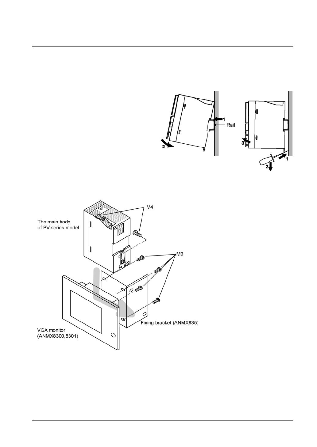
2.2.2 Mounting the PV310
There are the two ways to mount the PV310, by using screws or by hooking on the DIN rail.
Mounting the PV310 on the DIN rail
The PV310 can be mounted on or removed from a 35 mm wide DIN rail (DIN EN50022) with a single easy
operation.
To mount the PV310 on the DIN rail:
1. Hook the PV310 onto the DIN rail.
2. Press the lower part of the PV310 to fix it into
position.
To remove the PV310 from the DIN rail:
1. Insert the slot-head driver into the mounting
lever.
2. Press the mounting lever downward.
3. Lift and detach the PV310.
Mounting the PV310 to the VGA Monitor
If you want to mount the PV310 on the VGA monitor, use the fixture (ANMX835).
13

2.3 VGA Monitor Installation Environment
2.3.1 Installation Environment
Avoid installing the VGA Monitor in the Following Types of Locations:
• Locations with environmental temperatures that exceed a range of 0°C to 40°C
• Locations with a relative humidity exceeding a range of 20%RH to 85%RH
• Locations with a condensing due to a sharp temperature change
• Locations with an atmosphere containing corrosive gases or flammable gases
• Locations with a lot of dust, oily smoke and conductive dust
• Locations with a lot of fine particles, iron filings or salt
• Locations with an atmosphere likely to contain organic solvents (such as benzene, paint thinner,
and alcohol) or strongly alkaline materials (such as ammonia and caustic soda)
• Locations subject to direct vibration or impact
• Locations subject to direct sunlight
• Locations where the product can become wet with water, oil or chemicals
• Locations where the product is applied with excessive load
Noise Countermeasure
• Keep the PV310 as far away from the product that generates large switching surges, such as
high-voltage cable, high-voltage equipment, power cable and power equipment as possible.
• Keep as far away from the transmitting device (radio equipment, etc) as possible.
• Wire between the high-voltage line or power line and the DC power cable, VGA monitor cable or
keypad cable by using a duct or by keeping as much space between the lines and cables as
possible.
14
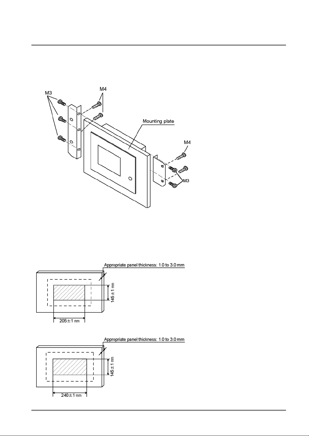
2.3.2 VGA Monitor Installation
To install the VGA monitor:
1. Insert the VGA monitor into the mounting plate.
2. Install the fixing fitting into the ditch of the VGA monitor using M3 screws and fix the VGA
monitor on the mounting plate using M4 screws.
Mounting Plate Cutting Dimensions
• When fixing the monitor or parts on the mounting plate or wiring the cables, it is recommended to
keep 30 mm to 50 mm spaces around the ANMX830* to prevent the cables from being damaged and
to increase work efficiency.
• Never block the ventilation slits.
ANMX8301
ANMX8300
15
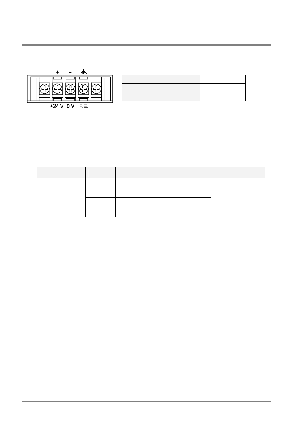
2.3.3 VGA Monitor: Power Wiring
Pin Assignments
Rated Voltage
Tolerance Voltage Range
Rated Consumption Current
Applicable Solderless Terminal
• Terminal screws are M3.
• It is suggested that solderless terminals are used to perform wiring. If you do not use a solderless
terminal, use the wires of which diameter is 0.5 mm
• Use up to 0.8 N•m of a tightening torque for fixing the terminal block. Failure to do so might damage
to the product.
Manufacturer Shape Model No. Applicable wire Tightening torque
JST Mfg. Co., Ltd.
R-type 1.25-MS3
A-type 1.25-B3A
R-type 2-MS3
A-type 2-N3A
2
to 1.25 mm2
0.25 mm
1.04mm
2
to 1.65 mm2
2
to 2.63 mm2
24 V DC
22.8 to 25.2 V DC
Less than 0.5 A
0.5N•m
16
 Loading...