

Page 1
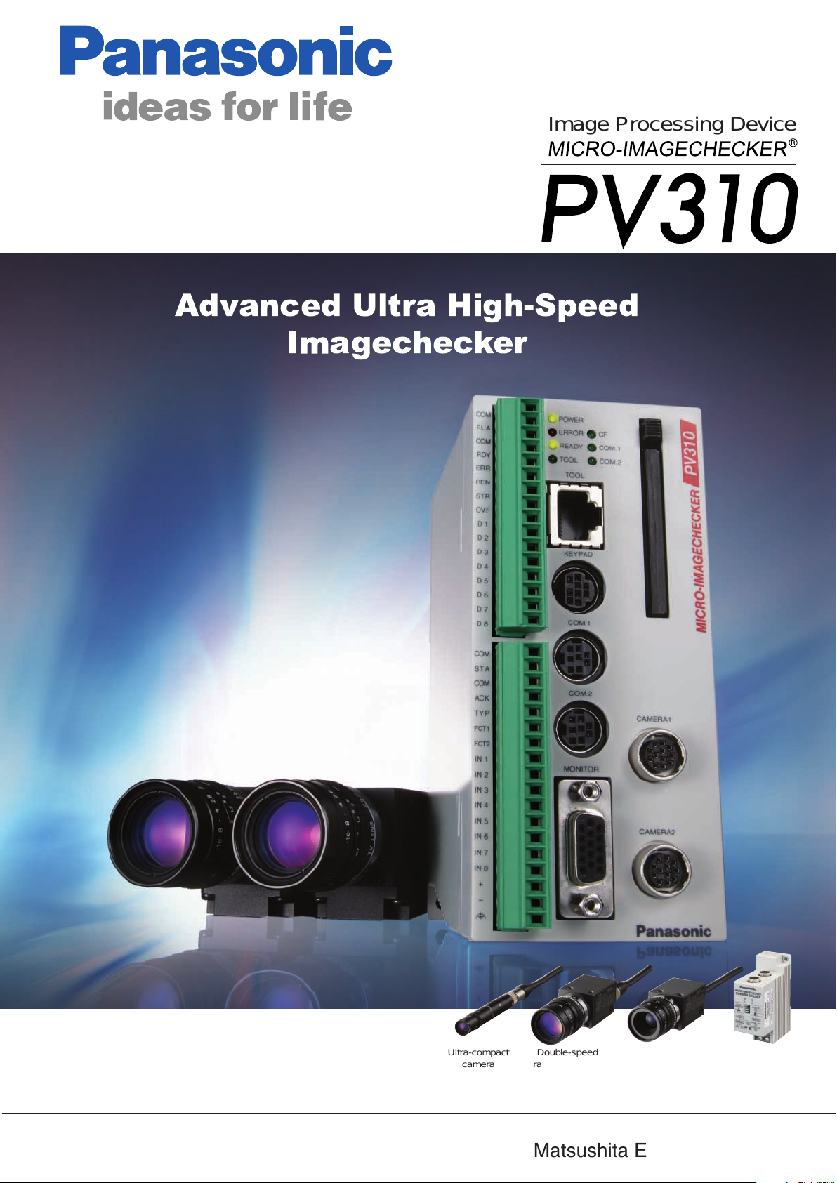
Image Processing Device
Advanced Ultra High-Speed
Imagechecker
http://www.mew.co.jp/ac/e
Ultra-compact
camera
Image Processing Device MICRO-IMAGECHECKER PV310
ARCT1B268E-2 '07 2
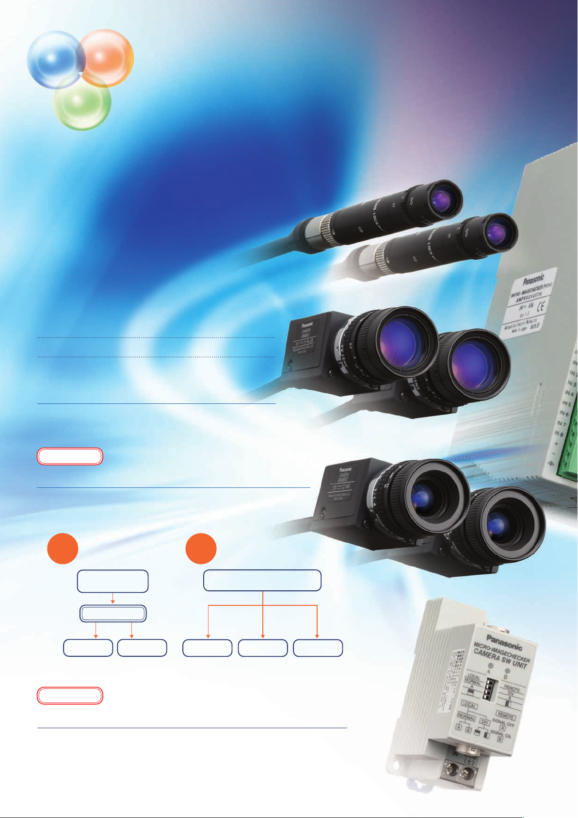
Double-speed
random camera
Standard camera Camera switching
Matsushita Electric Works, Ltd.
unit
Page 2
High
Performance
RISC-CPU
Image
Processor
Software
Optimization
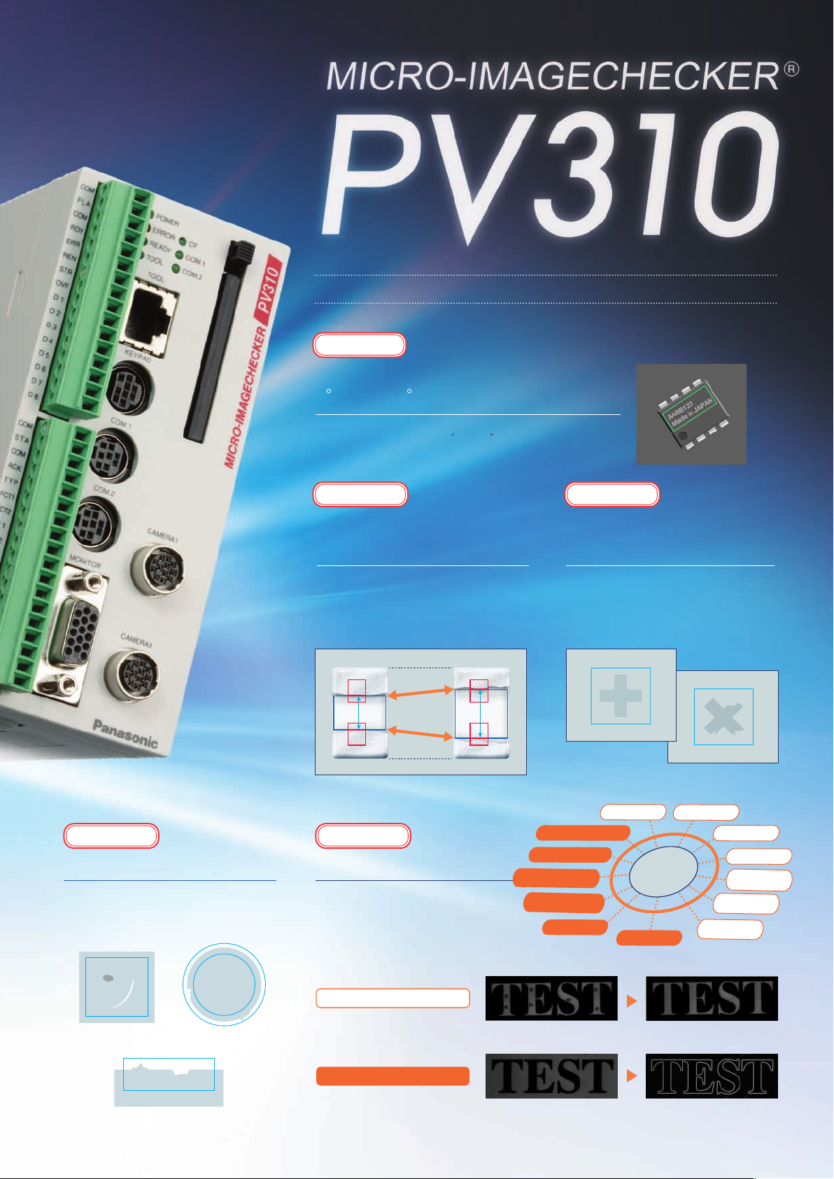
The PV310 achieves ultra high-speed image processing by:
• utilizing two processors
(image processor + high-performance RISC CPU)
• optimizing its software
(unique, high-speed image processing algorithm)
Excellent Peripheral Functions of the PV310
Ultra-Compact Camera
(12 mm diameter)
Ultra-compact camera have been added to the conventional variety of
cameras already supported. This facilitates miniaturizing target
equipment and retrofitting cameras in narrower spaces.
New Function
Branch Execution/Designated Execution
Change inspection routines immediately! Tooling changes are a thing of
the past!
Branch
execu-
tion
Branches the instruction
stream to choose an
inspection to be executed
depending on the test results.
Start signal input
Execute Block 1
Test + Judgment
OK NG
Desig-
execution
Provides high-speed
execution without tooling
nated
changes, reducing time for
inspections.
Start signal input
(Designate the inspections to be executed)
Inspection 1 Inspection 2 Inspection 1 Inspection 2 Inspection 3
Block 1Execute Block 2 Execute Block 3 Block 2 Block 3
<Three different inspections>
New Function
Image Data Transfer and Storage When Running
Image data can be saved on a CF card even during inspection, which allows you to
examine the data in your office at your convenience or transfer configuration settings to
another Imagechecker.
You can also transfer image data via Ethernet. You can set the file name to be transferred,
image output method, etc. The software which allows you to receive data is available on
our website free of charge.
2 3
Page 3
Enhanced Functionality, Improved Performance
Improved
Smart Matching From
0 to 360
The matching function has been improved to inspect
workpieces rotated from 0 to 360.
New Function
Auto Area
Adjustment
The inspection area can be
automatically adjusted to the workpiece
size to cover slight variations
(dimensional tolerance of workpieces).
New Function New Function
Flaw Detection
Scratches, stains, chipped edges, burrs
and other defects that could previously
only be detected by a more upscale
model can now be detected.
Filters Increase Reliability
13 filters are available to increase
the reliabilty and accuracy of
inspections. You may combine up
to 5 filters.
Auto
adjustment
New Function
Low Contrast
Matching
The workpiece can be detected even if
the contrast to the background is low or
if the workpiece itself is damaged.
Detects low-contrast
images.
Edge enhancement
Laplacian
Edge detection:
Y direction
Edge detection:
X direction
Sobel
Expansion
Workpiece
Prewitt
Detects partly chipped
images.
Contraction
Median
Smoothing
Expansion →
Contraction
Contraction →
Expansion
Background
cutting
Surface scratches
and stains
Chipping and burrs
Chipping and burrs
Filter useful for noise removal
•
Expansion → Contraction
(Black noise removal)
Filter useful for contour extraction
•
Sobel
(Edge detection)
Page 4
High-Speed Enhancements
[High Speed 1]
Smart Matching
Detects the presence (or absence) of a pattern (object) in
the search area that matches the template registered.
Detection of sub-pixel position possible with gray scale
matching. In addition, using the gray scale differential
processing function, shape inspection, e.g. to detect chips
or other flaws in an object, can also be carried out
simultaneously.
[High Speed 2]
Feature Extraction
Features, such as the number of objects, the area, central
coordinates, angle of the main axis, projection width or
perimeter length, can be extracted using a binary image.
High
Performance
RISC-CPU
Software
Optimization
[Processing Time]
Previous Model: 36.0 ms
3.8 ms
PV310:
Condition: Without orientation
correction
Template: 128 x 128
Search area: 512 x 480
[Processing Time]
Previous Model: 61.0 ms
3.9 ms
PV310:
Condition: With orientation
correction
Template: 486 x 452
Object color: Black
Image
Processor
Approx.
10
times faster than
previous model
Approx.
16
times faster than
previous model
Detects registered
template
Detection Image
[High Speed 3]
Gray Scale Window
An area can be created in a 256 gray scale image, with a
rectangular, circular or polygonal shape over the area
where object detection is to take place. An average value
for the brightness data (gray scale value) for all pixels in
that area can be calculated.
[High Speed 4]
Gray Scale Edge
The distance between lead pins or pitch size can be
measured for an inspection object. Parameters allow settings
to be made in great detail. Using the extreme accuracy of
sub-pixel processing, the edge in question can be reliably
extracted for a wide variety of object states.
[Processing Time]
Previous Model: 69.0 ms
1.7 ms
PV310:
Condition: With orientation
correction
Inspection area: 486 x 452
[Processing Time]
Previous Model: 28.0 ms
2.7 ms
PV310:
Condition: With orientation
correction
Inspection area: 200 x 160
Approx.
40
times faster than
previous model
Approx.
10
times faster than
previous model
Binary Window
Judges whether a certain amount of area for an object is present
using a binary image. High-speed processing is 23 times as fast
as previous models, even when multiple inspection areas are
specified.
4 5
[Processing Time] PV310: 2.1 ms Previous Model: 49.1 ms
Conditions: With orientation correction, inspection area: 486 x 452
Conditions: With orientation correction, inspection area: 486 x 452
Binary Edge
Determination of position and simple size measurement can be
carried out at approximately twice the speed of previous models. There
is no effect on inspection speed even if the inspection area is
increased for purposes of stability.
[Processing Time] PV310: 0.9 ms Previous Model: 1.8 ms
Conditions: With orientation correction, inspection area: 200 x 160
Page 5

User-Friendly Interface
An operation keypad makes configuration as easy as child's play.
The color display is easy to read and allows you to grasp information quickly.
Rich Information Display
The high performance VGA monitor displays inspected objects on the screen with high fidelity. Operations and settings can be
carried out easily via the pull-down menus and keypad.
Readability has been improved by displaying guidelines and character information in color and using a large character font.
In addition, parallel inspection output results can be monitored in color.
Status Display Area
Currently Selected Model Number,
Model Title and Shutter Speed
Currently Displayed Image Type
Message Area
Displays various messages, sub-windows for
checker settings and checker test results.
Overall Judgment Result
Displays OK (in green) when the output
judgment meets the judgment requirements
set in "Overall Judgment"
Signal Output Status
When the following signals are output, the
box below each signal is illuminated. (RUN
mode only)
R: READY signal
E: ERROR signal
1~8: D1 to D8 signals
Execution Time
Menu Bar
Displays menus for
setting inspection
conditions and the
inspection environment.
Screen Display Area
<RUN mode>
Displays images, checker
areas, inspection results,
etc. depending on the
settings in Settings Mode.
<Settings Mode>
Displays images, checker
areas, etc.
Settings windows called
from the menu bar are also
displayed in this area.
Menu Background Settings
A semi-transparent mode, allowing operations to be carried out while viewing captured images,
and a fill mode, which blocks out background colors, are both supported. You can select the menu
background color and set it as default.
Operation
keypad
Just position the cursor on a
menu item and press
<Enter>.
Semi-Translucent Mode
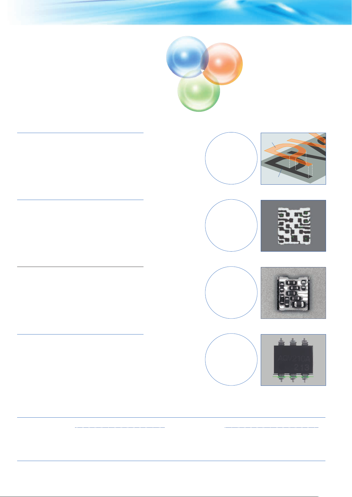
The PV310 can be used for a wide range of applications where high-speed processing is required, e.g.
Applications
inspecting:
Presence/absence of parts
Part size
Part orientation
Presence/absence of date or
serial no.
Product nameplate label
Remote control switch printing
Cap tightness
Fill Mode
Logo mark printing
Flat cable width
Label position
Debris/dirt on part
7-segment illumination
Substrate positioning
Metal part picking, etc.
Data Monitor
Up to 50 inspection results can be displayed in
a list on the monitor, allowing the operator to
check the results on the monitor. Threshold
adjustment (upper and lower limit values) can
also be changed on the data monitor without
having to enter them in the settings menu.
The size and display position can also be
changed.
Page 6

Full Selection of Interfaces
External interfaces are essential for image processing
devices of the future. The PV310 is equipped with a full
selection of interfaces that rival even large-scale devices.
Ethernet Connection
• The PV310 can be connected to a LAN using high-speed Ethernet
(100BASE-TX) to meet various application requirements.
• Captured images and measurement data can be transmitted to a PC at
high speed even during operation.
• The inspection status of multiple PV310 units can be monitored from a
single PC.
• With the high-speed connection to a PC, backing up image data is also
easy.
PC
Operation Keypad
The dedicated keypad with an
ergonomic structure provides
excellent operability.
External Memory (CF Card) Support
In RUN mode:
•
• Can save captured images.
[Storage capacity:
Approx. 2,000 images (512 MB)]
• Saves inspection results.
Facilitates trend tracking and data
analyses.
In the setting mode:
•
• Backs up setting data and image data
captured by the unit.
Note: Backup image data can be used as
regular bitmap files on a PC.
DIN Rail Installation
Connection of up to Two
Identical Cameras
Up to two identical cameras can be
connected. The following camera types
are available.
Standard camera
[ANM832 (CE)]
Double-speed random
camera [ANM831]
PLC Link Function
• The PV310 can communicate easily with external
devices, such as PLCs, using the RS232C port.
• The PV310 can be connected to other companies'
PLCs without requiring additional programming. Of
course it can be connected to our PLCs, too.
Supported Models:
• Matsushita Electric Works PLCs
• OMRON Corporation - C, CV and CS1 series
• Mitsubishi Electric Corporation - A, Q and FX series
• Rockwell Automation DF1 protocol
• Fuji Electric SX series
VGA Monitor
Judgment results and program
settings are displayed in color for
outstanding visibility.
(Captured images are in black
and white.)
Note: Commercially available VGA monitors may also be connected
(devices supporting horizontal synchronous frequency: 31.466KHz
and vertical synchronous frequency: 59.94KHz only.)
Operation cannot be guaranteed with devices from other manufacturers.
Ultra-compact camera
[ANPVCA1012]
PV310
Two cameras
Connection of up to Four Cameras
by a Camera Switching Unit
Up to four identical standard or double-speed random cameras can be
connected using a camera switching unit (option: ANPV3700).
* Excluding Ultra-compact camera
This connection is ideal for:
• Control of different inspections by a single controller unit
• Inspection of wide areas, and positioning of workpieces during the LCD
lamination process, etc.
PV310
Camera switching unit
(ANPV3700)
Cameras
Camera Switching Mode
•
Images taken by either of two cameras
connected to the camera switching unit
are output to the PV310.
* Available for ANM832 (CE) and
ANM831
Camera Image Split Mode
•
(top/bottom split and left/right split)
Half images taken by two cameras are
combined into one, which is then
output to the PV310.
* Available for ANM832 (CE) only
6 7
Page 7

Functions
Inspection programs for as many
as 64 product types can be set.
Upgraded
Improved
Smart Matching
Detection of sub-pixel position possible with gray
scale matching. In addition, using the gray scale
differential processing function, shape inspection,
etc. can also be carried out simultaneously. Memory
capacity has been increased 4 times over previous
models, allowing support for an even wider range of
applications.
Detects registered
template
Detection Image
Feature Extraction
Features, such as the number of objects, workpieces,
area, central coordinates, angle of the main axis,
projection width or perimeter length can be extracted.
Differential Function
Based on the position information obtained by the
matching function, the registered object and detected
object are overlapped and compared on a pixel-bypixel basis. Any pixels with a difference in brightness
over a certain level are detected. The area value of
such pixels can then be used to make pass/fail
judgments.
Template
Matching
detection
Difference detected =
NG
Gray Scale Window
An inspection area can be created in a 256 gray
scale image, with a rectangular, circular or polygonal
shape, over the area where object detection is to take
place. An average value for the brightness data (gray
scale value) for all pixels in that area can be
calculated.
Numerical Calculation/
Judgment Output
The numerical output function has been greatly
simplified so that even a novice can set it easily.
Operation has also become even easier as both
numerical calculations and judgment output can now
be set on the same screen (up to 96 formulas).
360° Contour Matching
Stable position detection is possible even for objects
that overlap because their contours can be extricated.
The range of settings has been doubled and support
has been added for 4 cameras.
Rotation/Position Adjustment
Highly accurate and reliable inspection is realized by automatically adjusting object orientation
and stop position deviation.
Complicated adjustments are also possible using the multiple adjustment function.
Multiple Adjustment
Position
adjustment 1
Detection Image
Position
adjustment 2
Search area Inspection object
Position Adjustment
Rotation Adjustment
Multiple Adjustment
Priority Adjustment
Previous
PV310
Mask
The shape of the inspection area can be set to
match particular targets. Mask area settings
can also be combined to allow efficient
inspections to be carried out only on the
necessary parts.
Inspection
area
Mask
Mask
Page 8

Settings
A full range of inspection modes to meet customers' needs. Support functions for optimal settings.
Setting Help
This function helps the user make settings that in the past relied heavily on human judgment, e.g. setting the focus, adjusting
the aperture, finding the optimal settings for the parallel monitor, lighting adjustment, density profile display, etc.
Density Profile Parallel Monitor
Collective Movement
Checkers that have been set can be moved
collectively all at once. This is useful for fine
adjustment when re-setting cameras. It is also
convenient when transferring product type data to a
different device.
Collective
Collective
Movement
Movement
Image Storage
Using a calendar function, the date a defect was
discovered and the number of inspections can be
added to saved color images. This is useful for later
verification (checking a defective product against a
saved image) and for analyzing defect tendencies.
Gray scale values for the image are displayed
in an easily understandable table.
Security
Passwords can be set in "environment" - "initial
settings". Vital setting data can be protected from
careless operating errors.
Global Support
(Multi-language Display & CE
Compliance)
Considering that the device may be shipped
overseas, the display can be switched between 6
different languages. The controller and dedicated
cameras are standardized items and CE compliant.
(Japanese)
The "Parallel Monitor" function is also useful during
actual operation for monitoring parallel input and
output signals to and from the PV310.
Inspection Mode
The PV300 is equipped with a variety of inspection
modes, such as position adjustment, rotation
adjustment, gray scale and binarization, to support a
wide range of inspection needs.
Position
Adjustment
Rotation
Adjustment
Binary Window
Gray Scale Window
Gray Scale Edge
Binary Edge
Feature Extraction
Binary Edge
Gray Scale
Edge
Feature
Extraction
Matching
Binary
Horizontal Edge
Binary Vertical
Edge
Gray Scale
Horizontal Edge
Gray Scale
Vertical Edge
Feature
Extraction
Matching
(Two checkers)
Contour
Matching
360 Matching
Smart Matching
Contour Matching
Flaw Detection
(English)
Selection is easy using
the Environment Settings Language menu.
8 9
Page 9

Support
Our popular menus and support software greatly improve workability during inspections.
Download from
CF Card
A program stored on a Compact Flash card
can be downloaded to the controller unit using
a parallel external signal.
CF Card
Statistical Support Print Screen
Statistical data such as the maximum, minimum and
average data values, number of failed results, etc.
can be displayed. Maximum, minimum and average
values in pass judgments can be checked, allowing
them to be used as a guide for subsequent upper and
lower limit settings.
Parallel Handshake Support
Parallel external output of 96 inspection and numerical calculation results is available.
Display and settings screens can be saved to
a memory card as bitmap files. This is
convenient for creating documents or for
checking previous images.
Full Peripheral Support with "AXTOOL" Vision Support Tool
The "AXTOOL" Vision Support Tool is full of enhanced functions and connects to PV310s
using a high-speed interface (100BASE-TX) to meet various application requirements.
PC
Ethernet
100BASE-TX
1. Backup/recovery of image and settings data
2. Copy/move/deletion of image and settings data
3. Check saved images on PC
4. Convert settings data to CSV format. Editing possible with Excel.
PV310
Product type
data backup
screen
Document
display screen
Image data
display screen
Download AXTOOL for free from:
http://www.mew.co.jp/ac/e/fasys/vision/
Note: The screen design may differ from that shown.
Page 10

Dimensions (Unit: mm)
Main Unit (Controller)
ANPV0310EDN
4.6
5
(10)
Operation Keypad
10059
130
(5) (Pullout dimensions)
ANM852**
ANM852**CE
54.4
ENTER
B
A
C
46
124.6
18
L
11.5
Double-Speed Random Camera: C Mount
ANM831
Without mounting bracket
29
2-M3
31
(
Depth
4mm)
54.5
(46.5)
8
24.5±0.6
19
13
4-M3
(
Depth
Ultra-Compact Camera
ANPVCA1012
(6.4)39.4±1
5.65
3.5
M10.5 P=0.5
12±0.1
2.42
9 (length toCCD)
(in air 7.4mm)
CCU
110±3
70
1
±
28
(3.1)
10
2.5mm)
0.6
±
26
156±3
Standard Camera: CS Mount
ANM832/ANM832CE/ANM83203
*1)
8
29
14
24.5±0.2
8
4mm)
Without mounting bracket
49.5
( 6.7)
4-M3 (
(19)
(31.3)
24.5
(3.25)
31
31
1/4-20UNC
±
0.6
(
Depth
9mm)
31
With mounting bracket
2.5
2-M3 (
Depth
0.2
±
26
Double-Speed Random Camera Cable
ANM84303
( 12.5)
9131
ANM84303CE
*2)
(43)
( 14.7)
Note *2) This is the length of cable in use.
Becomes slightly shorter with CE attached.
7.0
Camera Extension Cable
ANM840 A
ANM840 ACE
(43)
7.0
( 14.7)
(43)
L
The boxes correspond to the length of cable in use.
(43)
Depth
2.5mm)
Double-Speed Random Camera Cable
(Durable Type)
ANM84603
Camera Extension Cable (Durable Type)
ANM845
( 14)
( 11.9)
2-M3 (
( 14.7)
( 14.7)
( 14.7)
Depth
Note *1)
ANM832: 3000
ANM832CE: 2780
ANM83203: 300
7mm)
18.15
0.2
±
23
32.15
With mounting bracket
(52)
(52)
38
28±0.2
3000±50
7.9
7.9
1/4-20UNC
L
0.2
±
10.5
Depth
10mm
(52)
(52)
( 14)
( 11.9)
Lens
Mounting screws (lenses with lock only)
A
VGA Monitor
ANMX8301
C Mount Lens
ANB843L
ANB845NL
ANB846NL
ANB847L
ANM88161
ANM88251
ANM8850
B
B
A
55 55
ANM88501
Ultra-Compact Lens
ANPVL0401
ANPVL1201
ANPVL3001
258
255
f=8.5
f=16
f=25
f=50
f=16
f=25
f=50
f=50
f=4
f=12
f=30
AB
φ42
40
φ30
33
φ30
37.3
φ48
48
φ30.5
25
φ30.5
25.5
φ27.5
38.5
φ30.5
38.5
AB
φ12
14.8
φ12
14.4
φ12
25.3
45
2
43
3540
10
160
Camera Switching Unit
ANPV3700
ANMX8301
36
26.5±0.5
5.4
5
5
0.5
±
86.0
5.5
5.4
55 55
9.5 (Pullout dimensions)
223
220
74.6
51.4
59
29.5
25.4
7.2
96
35.4
48
DIN hook
45
2
43
90
160
Keypad hole
Without Keypad
Connector
31
Keypad Cable
(between VGA monitor and
controller)
ANMX8333*
With Keypad Connector
40
12
L
40
12
VGA Monitor Cable
ANMX8331*
57
31
18
L
10 11
Page 11

Part Nos. and Specifications
Part Nos.
Product Name
PV310 Controller
Double-Speed Random
Camera (C Mount)
Standard Camera
(CS Mount)
Double-Speed
Random Camera
Cable
Ultra-Compact Camera
Camera Extension
Cable
Camera Switching
Unit
VGA Monitor
Kit for
Installation
on Main Unit
Controller
Mounting
Brackets
Monitor
Cable
(With keypad
controller)
Keypad Cable
for Connection
to Main Unit
C Mount
Lens
UltraCompact
Camera Lens
Adapter Ring
Operation Keypad
COM Port
Cable
Specification Part No.
JPN/ENG
JPN/ENG
ENG/JPN
ENG/GER/FRN/ITA/SPN
progressive support
with 3 m cable
with 3 m cable
with 30 cm cable
3 m
3 m
Double-Speed Random
Camera Cable
(Durable Type) = 3 m
12-mm diameter
2 m extension: Total 5 m
7 m extension: Total 10 m
12 m extension: Total 15 m
17 m extension: Total 20 m
2 m extension: Total 5 m
7 m extension: Total 10 m
12 m extension: Total 15 m
17 m extension: Total 20 m
Durable extention 2 m: Total 5 m
Durable extention 7 m: Total 10 m
Durable extention 12 m: Total 15 m
Durable extention 17 m: Total 20 m
Supports standard camera
and double-speed random
camera
With keypad connector
Without keypad connector
With keypad connector.
Mounting brackets
(ANMX835)/Monitor cable:
0.5 m/Keypad cable: 0.5 m
Without keypad connector.
Mounting brackets
(ANMX835)/Monitor cable:
0.5 m
Brackets for mounting
VGA monitor on the
controller
Cable length: 0.5 m
(for single-unit mounting)
Cable length: 1 m
Cable length: 2 m
Cable length: 3 m
Cable length : 0.5 m
Cable length: 1 m
Cable length: 2 m
Cable length: 3 m
C mount lens with lock
f8.5
C mount lens with lock
f16
C mount compact lens with lock
f16
C mount compact lens
f25
C mount compact lens with lock
f25
C mount super-compact lens with lock
f50
C mount super-compact lens with lock
f50
C mount super-compact lens
f50
f4
Ultra-Compact Lens 12mm
f12
Ultra-Compact Lens 12mm
f30
Ultra-Compact Lens 12mm
5 mm
0.5/1/5/10/20/40 mm
with 2 m cable
with 3 m cable
with 5 m cable
with 10 m cable
with 2 m cable
with 3 m cable
with 5 m cable
with 10 m cable
for connection to PC
(D-SUB: 9 pins): 3 m
for connection to PLC
(discrete-wire cable): 3 m
CE
NPN
PNP
NPN
PNP
ANPV0310JDN
ANPV0310JDP
ANPV0310EDN
ANPV0310MDP
ANM831
ANM832
ANM832CE
ANM83203
ANM84303
ANM84303CE
ANM84603
ANPVCA1012
ANM84002A
ANM84007A
ANM84012A
ANM84017A
ANM84002ACE
ANM84007ACE
ANM84012ACE
ANM84017ACE
ANM84502
ANM84507
ANM84512
ANM84517
ANPV3700
ANMX8300
ANMX8301
ANMX8302
ANMX8303
ANMX835
ANMX83310
ANMX83311
ANMX83312
ANMX83313
ANMX83330
ANMX83331
ANMX83332
ANMX83333
ANB843L
ANB845NL
ANM88161
ANB846NL
ANM88251
ANB847L
ANM8850
ANM88501
ANPVL0401
ANPVL1201
ANPVL3001
ANB84805
ANB848
ANM85202
ANM85203
ANM85205
ANM85210
ANM85202CE
ANM85203CE
ANM85205CE
ANM85210CE
ANM81103
ANM81303
General Specifications
Controller: ANPV0310
Specification
Specification
Product Name
Product Name
Item
Rated Operating Voltage
Rated Operating Voltage
Rated Operating Voltage
Operating Voltage Range
Operating Voltage Range
Operating Voltage Range
Rated Current Consumption
Rated Current Consumption
Rated Current Consumption
Ambient Temperature (in use)
Ambient Temperature (in use)
Ambient Temperature (in use)
Storage Ambient Temperature
Storage Ambient Temperature
Storage Ambient Temperature
Ambient Humidity (in use and storage)
Ambient Humidity (in use and storage)
Ambient Humidity (in use and storage)
Noise Immunity
Noise Immunity
Noise Immunity
Vibration Resistance
Vibration Resistance
Vibration Resistance
Shock Resistance
Shock Resistance
Shock Resistance
Weight
Weight
Weight
Dimensions (mm)
24 V DC
24 V DC
24 V DC
21.6 to 26.4 V DC (including ripples)
21.6 to 26.4 V DC (including ripples)
21.6 to 26.4 V DC (including ripples)
0.7 A max. (1 camera) 0.9 A max. (2 cameras)
0.7 A max. (1 camera) 0.9 A max. (2 cameras)
0.7 A max. (1 camera) 0.9 A max. (2 cameras)
0 to 50∞C (no freezing or condensation)
0 to 50∞C (no freezing or condensation)
0 to 50°C (no freezing or condensation)
-20 to +60∞C (no freezing or condensation)
-20 to +60∞C (no freezing or condensation)
-20 to +60°C (no freezing or condensation)
35 to 75%
35 to 75%
35 to 75%
1000 V pulse width 50 ns/1 µs
1000 V pulse width 50 ns/1 µs
(using noise simulator method)
(using noise simulator method)
10 to 55 Hz, 1 cycle/1 min.
10 to 55 Hz, 1 cycle/1 min.
Double amplitude of 0.75 mm.
Double amplitude of 0.75 mm.
30 min. each in X, Y and Z directions
30 min. each in X, Y and Z directions
196 m/s2, 5 times each in X, Y and Z directions
196 m/s2, 5 times each in X, Y and Z directions
Approx. 450g
Approx. 450 g
W59 × H130 × D100 (with connector 110)
Specification
(at 25∞C with no freezing or condensation)
(at 25∞C with no freezing or condensation)
(at 25°C with no freezing or condensation)
Functional Specifications
Functional Specifications
Specification
Settings Data Storage Capacity
Frame Memory
Operation
Environment
Cameras
Monitor Output
Input/Output
Memory Card
Serial
Parallel
Keypad Input
Tools
Image Processing Functional Specifications
Item
Monitor Display
Number of Connected
Cameras
Processing Method
No. of Product Types
Inspection Functions
Numerical
Computation
Judgment Output
Statistics
Data Monitor
Approx. 4 MB
512 x 480 (pixels)
Menu selection by dedicated keypad
Key Emulation
Menu selection by serial command
2 Standard cameras, double-speed random
cameras, or ultra-compact cameras
(max. 4 cameras when using camera switching
unit, excluding ultra-compact camera)
Color VGA ouput
Compact Flash: 1 slot
RS-232C x 1 channel
Input: 13 points; output: 14 points;
removable screw-down terminal block
1 Connector for dedicated keypad (ANM8520*)
Ethernet: 1 channel
Specification
Full color VGA/gray scale image/
binary image
Two-screen compressed display: side-by-side
display (when gray scale image selected)
through/memory, data monitor, marker,
+ information display region (128x480)
Max. 2 cameras (Max. 4 cameras using camera
switching unit, excluding ultra compact camera)
Gray scale processing - Binary processing
Max. 64 types
(depends on settings data capacity)
Max. 99 checkers/product type
•Position adjustment, rotation adjustment,
binary window
•Gray scale window, binary edge, gray scale
edge
•Feature extraction, smart matching, contour
matching, scratch detection
Max. 96 functions/product type
Operators:
4-operation calculation, , arc tangent,
distance between 2 points,
parenthesis, sin, cos, absolute value of
difference
Max. 96 functions/product type
Operators:
NOT/AND/OR/XOR/parenthesis
Max. 96/product type
Calculation of no. of passes/no. of fails/pass
average/pass distribution/
pass max. value/pass min. value/pass range
(for judgment output no. of passes/no. of fails
only)
Max. 50/product type
Displayed on screen in table form during RUN
Title input and substitution of numerical
computation results, judgment output results,
statistical results and product numbers
possible
Camera Switching Unit: ANPV3700
Specification
Item
Product Name
Camera Switching 2-camera input - 1-camera output
Camera Image Split
ANM832 (CE) only
Functions
External Switching
Signal Input
DIP Switch Setting LOCAL/REMOTE, NORMAL/DIV, A/B,
Rated Voltage Range 12 V DC (supplied from the MICRO-
Weight
Included items: 1 connection cable (30 cm), 2 ferrite cores, and
The operation condition requirements are the same as those for the PV310
Controller.
(Switching by external signal input/Manual switching)
2-camera input - 1-camera output of top/bottom
split images/
2-camera input - 1-camera output of left/right
split images
1 input, photo-coupler bidirectional input
supported, 5 to 24 V DC
Top-Bottom/Left-Right
IMAGECHECKER unit)
Approx. 150 g (Main unit only)
1 installation manual
ItemItem
Operation Data
Marker
Serial
External Input/Output
Parallel
Ethernet
(1 channel)
CF Card
(1 slot)
Display
Functions
Other
Collective
Movement
Image Storage
Setting Help
Calendar
Password
Max. 4/environment
Substitution in numerical computation possible
Max. 8/product type
Graphic display on screen during RUN
RS-232C=1ch (max. speed 115200 bps)
• Input: start/product type switch/camera
display switch/template re-registration/
CompactFlash settings restore/reference to
and alteration of upper and lower values for
numerical computation/reference to and
alteration of binary level/reference to and
alteration of gray scale edge thresholds/data
storage/fixed length input for input commands
for statistics initialization (for PLC)
• Output: output (no. of inspections/judgment
output/numerical computations/statistics)
synchronous or asynchronous to inspection
start trigger
• Computer link support:
Supported models:
• Matsushita Electric Works PLC
• OMRON Corporation - C, CV and CS1 series
•
Mitsubishi Electric Corporation - A, Q and FX series
• Rockwell Automation DF1 protocol
• Fuji Electric SX series
Input: 13 points; output: 14 points
• Input: start/product type switch/camera
display switch/template re-registration/
data restore from Compact Flash
• Output: ready/error/flush/image
acquired/strobe/judgment output data/
synchronous output (no. of inspections/
judgment output/numerical computation/
statistics) possible by handshake output
• Output: no. of inspections/judgment
output/numerical computations/statistics/
settings data/image backup and
restore/conversion to documentation for
settings data (Vision AXTOOL)
• Output: no. of inspections/judgment
output/numerical computations/statistics/
settings data/image backup and restore/screen
dumps
Transparent menu/parallel output status
monitor/reference coordinate display/checkers
with fail results highlighted in different color
Collective movement of set checkers in units
of position/rotation adjustment groups
Max. 16 images/camera
Each time/storage possible according to
judgment result
Test runs available on stored images
Display of date and time saved
Function to maintain display of last image
saved
Focusing/aperture adjustment/parallel monitor/
lighting adjustment/gray scale profile display
Calendar information added to stored images
File time stamp
Password function for when moving between
settings modes
Specification
Specification
Page 12

PV310
ARCT1B268E-2
ARCT1B268E-2 200702-2YT
http://www.mew.co.jp/ac/e
 Loading...