

Page 1

Operating Instructions
Functional Manual
LCD Projector
Model No.
PT-MW730
Thank you for purchasing this Panasonic product.
Commercial Use
PT-MZ770
■ This manual is common to all the models regardless of sufxes of the Model No.
zfor India
D: White model, the standard zoom lens supplied
zfor Asia (except for Taiwan, Korea) / Oceania
A: White model, the standard zoom lens supplied LA: White model, the lens sold separately
zfor Taiwan
A: White model, the standard zoom lens supplied
zfor Korea
Without L: White model, the standard zoom lens supplied
With L: White model, the lens sold separately (PT-MZ770L only)
zfor other countries or regions
Without L / LB: White model, the standard zoom lens supplied With L: White model, the lens sold separately
With LB: Black model, the lens sold separately (PT-MZ770LB only)
■ Before operating this product, please read the instructions carefully and save this manual
for future use.
■ Before using this product, be sure to read “Read this rst!” (x pages 5 to 15).
ENGLISH
DPQP1224ZB/X1
Page 2

Contents
Contents
Read this rst! 5
Chapter 1 Preparation
Precautions for use 20
Intended use of the product 20
Lens protection material 20
Cautions when transporting 20
Cautions when installing 20
Security 23
Notes regarding the wireless LAN 23
Light ID 24
DIGITAL LINK 25
Application software supported by the projector
25
Storing 26
Disposal 26
Cautions on use 26
Accessories 27
Optional accessories 28
About your projector 29
Remote control 29
Projector body 31
Preparing the remote control 34
Inserting and removing the batteries 34
When using the multiple projectors 34
Connecting the remote control to the projector
with a cable 34
Chapter 2 Getting Started
Setting up 36
Installation mode 36
Parts for installation (optional) 37
Projected image and throw distance 38
Adjusting adjustable feet 48
Removing/attaching the projection lens 49
Removing the projection lens 49
Attaching the projection lens 50
Attaching the Wireless Module 51
Attaching the Wireless Module 51
Connecting 52
Before connecting 52
Connecting example: AV equipment 53
Connecting example: Computers 54
Connecting example using DIGITAL LINK 55
Chapter 3 Basic Operations
Switching on/off the projector 58
Connecting the power cord 58
Power indicator 59
Switching on the projector 60
When the initial setting screen is displayed 61
Making adjustments and selections 65
Switching off the projector 66
Projecting 67
Selecting the input signal 67
Adjusting the focus, zoom, and lens shift 68
Moving the lens position to the home position 69
Adjustment range by the lens position shift
(optical shift) 69
Using the USB memory 70
Notes on use 70
USB memory that can be used with the
projector 70
Attaching the USB memory 70
Removing the USB memory 71
Operating with the remote control 72
Using the shutter function 72
Using the mute function 72
Adjusting the volume 73
Using the freeze function 73
Using the on-screen display function 73
Using the automatic setup function 74
Using the screen adjustment function 74
Using the digital zoom function 75
Switching the image aspect ratio 76
Using the presentation timer function 76
Using the function button 76
Displaying internal test pattern 76
Using the status function 77
Using the ECO management function 77
Setting ID number of the remote control 77
Chapter 4 Settings
Menu navigation 80
Navigating through the menu 80
Main menu 81
Sub-menu 82
2 - ENGLISH
Page 3

Contents
[PICTURE] menu 85
[PICTURE MODE] 85
[CONTRAST] 85
[BRIGHTNESS] 85
[COLOR] 86
[TINT] 86
[COLOR TEMPERATURE] 86
[GAMMA] 87
[DAYLIGHT VIEW] 88
[SHARPNESS] 88
[NOISE REDUCTION] 88
[DYNAMIC CONTRAST] 89
[SYSTEM SELECTOR] 89
[POSITION] menu 91
[SHIFT] 91
[ASPECT] 91
[ZOOM] 92
[CLOCK PHASE] 93
[REALTIME KEYSTONE] 93
[SCREEN ADJUSTMENT] 94
[ADVANCED MENU] menu 97
[DIGITAL CINEMA REALITY] 97
[BLANKING] 97
[INPUT RESOLUTION] 98
[CLAMP POSITION] 98
[RASTER POSITION] 98
[DISPLAY LANGUAGE] menu 99
Changing the display language 99
[DISPLAY OPTION] menu 100
[COLOR ADJUSTMENT] 100
[COLOR CORRECTION] 100
[SCREEN SETTING] 101
[AUTO SIGNAL] 101
[AUTO SETUP] 101
[RGB IN] 102
[HDMI IN] 103
[DIGITAL LINK IN] 105
[ON-SCREEN DISPLAY] 106
[CLOSED CAPTION SETTING] (only when
NTSC signal is input) 108
[SIGNAL SEARCH] 109
[BACK COLOR] 109
[STARTUP LOGO] 110
[SHUTTER SETTING] 110
[P-TIMER] 111
[FREEZE] 11 2
[DIGITAL ZOOM] 11 2
[PROJECTOR SETUP] menu 11 3
[PROJECTOR ID] 113
[PROJECTION METHOD] 11 3
[ECO MANAGEMENT] 114
[LightID] 116
[INITIAL STARTUP] 117
[STARTUP INPUT SELECT] 117
[DATE AND TIME] 11 8
[SCHEDULE] 11 9
[RS-232C] 120
[REMOTE1 MODE] 122
[FUNCTION BUTTON] 122
[LENS CALIBRATION] 122
[AUDIO SETTING] 123
[FILTER COUNTER] 125
[DC OUT] 126
[STATUS] 126
[DATA CLONING] 127
[SAVE ALL USER DATA] 130
[LOAD ALL USER DATA] 130
[INITIALIZE] 131
[SERVICE PASSWORD] 131
[TEST PATTERN] menu 132
[TEST PATTERN] 132
[SIGNAL LIST] menu 133
Registering new signals 133
Renaming the registered signal 133
Deleting the registered signal 133
Protecting the registered signal 134
Expanding signal lock-in range 134
Sub memory 135
[SECURITY] menu 136
[SECURITY PASSWORD] 136
[SECURITY PASSWORD CHANGE] 136
[DISPLAY SETTING] 136
[TEXT CHANGE] 137
[MENU LOCK] 137
[MENU LOCK PASSWORD] 137
[CONTROL DEVICE SETUP] 138
[CONTROL DEVICE PASSWORD CHANGE]
139
ENGLISH - 3
Page 4

Contents
[NETWORK/USB] menu 140
[DIGITAL LINK MODE] 140
[DIGITAL LINK STATUS] 140
[DIGITAL LINK MENU] 141
[WIRED LAN] 141
[WIRELESS LAN] 142
[PROJECTOR NAME] 146
[NETWORK CONTROL] 146
[MEMORY VIEWER] 146
[Panasonic APPLICATION] 148
[MIRRORING] 150
[NETWORK STATUS] 151
Chapter 5 Operations
Network connection 154
Connecting via wired LAN 155
Connecting with the wireless LAN 157
Web control function 159
Computer that can be used for setting 159
Accessing from the web browser 159
Projecting with Panasonic APPLICATION input
179
Application that can be used 179
Connecting the device 179
Ending the connection with the device 179
Description of the standby screen 180
Using the moderator mode in the Panasonic
APPLICATION input 181
Projecting with MIRRORING input 182
Connecting the device 182
Ending the connection with the device 183
Using the moderator mode in the MIRRORING
input 183
Operating with the web browser 184
Description of the [MODERATOR MODE] page
185
Projecting with MEMORY VIEWER input 186
Images that can be played back with the
Memory Viewer function 186
Displaying the Memory Viewer screen 187
Operating the Memory Viewer screen 187
Playing back still images 189
Playing back movies 190
Description of the Memory Viewer screen 193
Playing back using the contents list 194
Using the pairing function 195
Pairing the USB memory 195
Maintenance/replacement 200
Before performing maintenance/replacement 200
Maintenance 200
Replacing the unit 202
Troubleshooting 204
FAQ 206
Wireless LAN connection 206
Mirroring connection 206
[SELF TEST] display 208
Chapter 7 Appendix
Technical information 211
PJLink protocol 2 11
Control commands via LAN 212
<SERIAL IN> terminal 215
<REMOTE 1 IN> terminal 219
Operating [MENU LOCK PASSWORD] 219
List of compatible signals 220
Specications 223
Dimensions 228
Precautions for attaching the Ceiling Mount
Bracket 229
Index 231
Chapter 6 Maintenance
Light source/temperature/lter indicators 198
When an indicator lights up 198
4 - ENGLISH
Page 5

Read this rst!
Read this rst!
WARNING: THIS APPARATUS MUST BE EARTHED.
WARNING: To prevent damage which may result in re or shock hazard, do not expose this appliance to rain
or moisture.
This device is not intended for use in the direct eld of view at visual display workplaces. To avoid
incommoding reexions at visual display workplaces this device must not be placed in the direct
eld of view.
The equipment is not intended for used at a video workstation in compliance BildscharbV.
The sound pressure level at the operator position is equal or less than 70 dB (A) according to ISO 7779.
WARNING:
1. Remove the plug from the mains socket when this unit is not in use for a prolonged period of time.
2. To prevent electric shock, do not remove cover. No user serviceable parts inside. Refer servicing to qualied
service personnel.
3. Do not remove the earthing pin on the mains plug. This apparatus is equipped with a three prong earthing-
type mains plug. This plug will only t an earthing-type mains socket. This is a safety feature. If you are
unable to insert the plug into the mains socket, contact an electrician. Do not defeat the purpose of the
earthing plug.
WARNING:
This equipment is compliant with Class A of CISPR32.
In a residential environment this equipment may cause radio interference.
(for Taiwan)
WARNING:
This equipment complies with the Class A standard of CISPR32.
This is Class A information technology equipment that may cause radio frequency interference when used in a
residential environment, in which the user will be required to take certain appropriate countermeasures.
CAUTION: To assure continued compliance, follow the attached installation instructions. This includes using
the provided power cord and shielded interface cables when connecting to computer or peripheral
devices. Also, any unauthorized changes or modications to this equipment could void the user’s
authority to operate this device.
This is a device to project images onto a screen, etc., and is not intended for use as indoor lighting in a
domestic environment.
Directive 2009/125/EC
WARNING: TO REDUCE THE RISK OF FIRE OR ELECTRIC SHOCK, DO NOT EXPOSE THIS PRODUCT
TO RAIN OR MOISTURE.
WARNING: RISK OF ELECTRIC SHOCK. DON’T OPEN
or
Indicated on the projector
The lightning ash with arrowhead symbol, within an equilateral triangle, is intended to alert the
user to the presence of uninsulated “dangerous voltage” within the product’s enclosure that may
be of sufcient magnitude to constitute a risk of electric shock to persons.
The exclamation point within an equilateral triangle is intended to alert the user to the presence of
important operating and maintenance (servicing) instructions in the literature accompanying the
product.
ENGLISH - 5
Page 6
Read this rst!
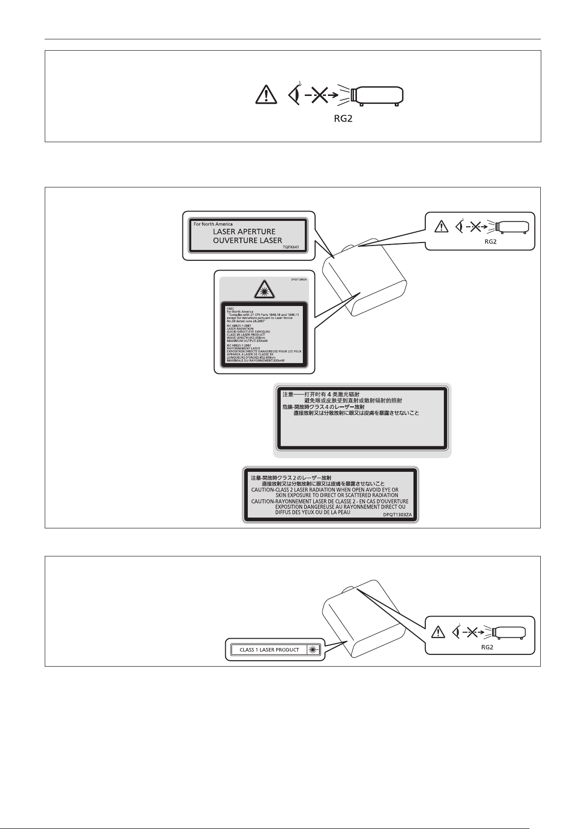
WARNING: Do not look at the light emitted from the lens while the projector is being used.
As with any bright source, do not stare into the direct beam, RG2 IEC 62471-5:2015.
Indicated on the projector
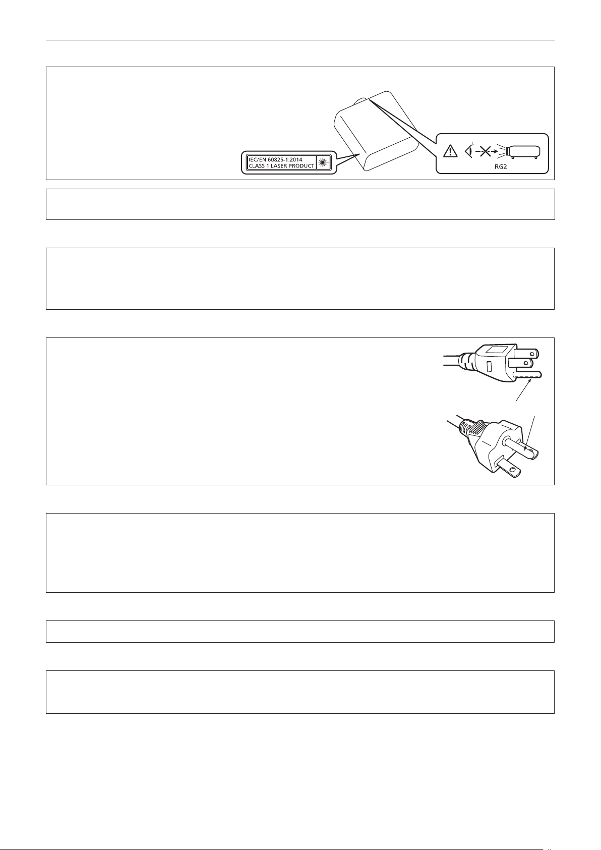
Notice on laser
(for USA and Canada)
This projector is the Class 3R laser product that complies with IEC 60825-1:2007.
DANGER-
CLASS 4 LASER RADIATION WHEN OPEN AVOID EYE OR
SKIN EXPOSURE TO DIRECT OR SCATTERED RADIATION
DANGER-
RAYONNEMENT LASER DE CLASSE 4 - EN CAS D'OUVERTURE
EXPOSITION DANGEREUSE AU RAYONNEMENT DIRECT OU
DIFFUS DES YEUX OU DE LA PEAU
(for India)
This projector is the Class 1 laser product that complies with IEC/EN 60825-1:2014.
DPQT1359ZA
(Inside of product)
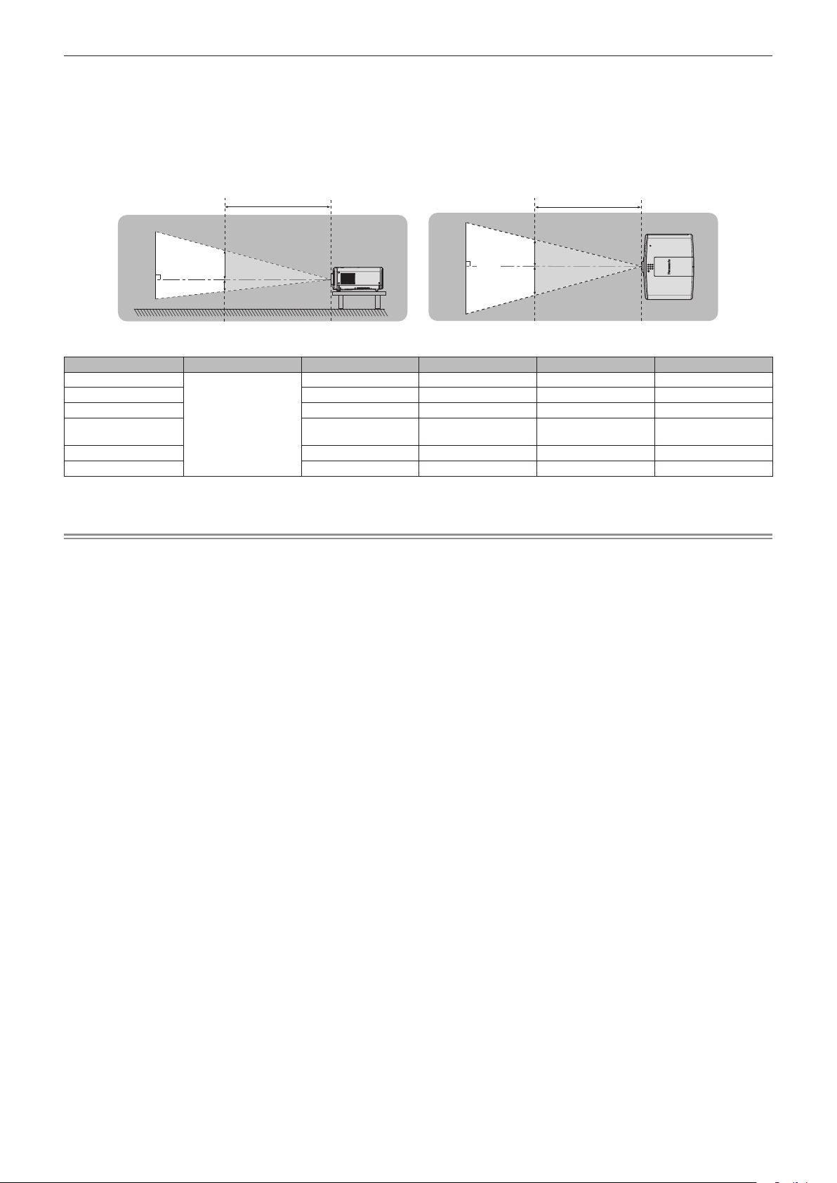
Indicated on the projector
6 - ENGLISH
Page 7
Read this rst!
(for other countries or regions)
This projector is the Class 1 laser product that complies with IEC/EN 60825-1:2014.
CAUTION: Use of controls or adjustments or performance of procedures other than those specied herein
may result in hazardous radiation exposure.
CAUTION (North/Middle/South America/Taiwan)
Power Supply: This Projector is designed to operate on 100 V - 240 V, 50 Hz/60 Hz AC, house current only.
CAUTION: The AC power cord which is supplied with the projector as an accessory can only be used for
power supplies up to 125 V. If you need to use higher voltages than this, you will need to obtain a
separate 250 V power cord. If you use the accessory cord in such situations, re may result.
CAUTION (North/Middle/South America/Taiwan)
This equipment is equipped with a three-pin grounding-type power plug. Do not
remove the grounding pin on the power plug. This plug will only t a grounding-type
power outlet. This is a safety feature. If you are unable to insert the plug into the
outlet, contact an electrician. Do not defeat the purpose of the grounding plug.
Do not remove
WARNING (USA and Canada)
fNot for use in a computer room as dened in the Standard for the Protection of Electronic Computer/Data
Processing Equipment, ANSI/NFPA 75.
fFor permanently connected equipment, a readily accessible disconnect device shall be incorporated in the
building installation wiring.
fFor pluggable equipment, the socket-outlet shall be installed near the equipment and shall be easily
accessible.
NOTIFICATION (Canada)
This class A digital apparatus complies with Canadian ICES-003.
For USA-California Only
This product contains a CR Coin Cell Lithium Battery which contains Perchlorate Material – special handling
may apply.
See www.dtsc.ca.gov/hazardouswaste/perchlorate
ENGLISH - 7
Page 8

Read this rst!
FCC NOTICE (USA)
Supplier’s Declaration of Conformity
Model Number: PT-MZ770 / PT-MZ770L / PT-MZ770LB / PT-MW730 / PT-MW730L
Trade Name: Panasonic
Responsible Party: Panasonic Corporation of North America
Address: Two Riverfront Plaza, Newark, NJ 07102-5490
General Contact: http://www.panasonic.com/support
Projector Contact: https://panasonic.net/cns/projector/
This device complies with Part 15 of the FCC Rules.
Operation is subject to the following two conditions:
(1) This device may not cause harmful interference, and (2) this device must accept any interference received,
including interference that may cause undesired operation.
Caution:
This equipment has been tested and found to comply with the limits for a Class A digital device, pursuant to part
15 of the FCC Rules. These limits are designed to provide reasonable protection against harmful interference
when the equipment is operated in a commercial environment. This equipment generates, uses, and can
radiate radio frequency energy and, if not installed and used in accordance with the instruction manual, may
cause harmful interference to radio communications. Operation of this equipment in a residential area is likely
to cause harmful interference in which case the user will be required to correct the interference at his own
expense.
FCC Warning:
To assure continued compliance, follow the attached installation instructions. This includes using the provided
power cord and shielded interface cables when connecting to computer or peripheral devices. Also, any
unauthorized changes or modications to this equipment could void the user’s authority to operate this device.
8 - ENGLISH
Page 9

Read this rst!
IMPORTANT: THE MOLDED PLUG
FOR YOUR SAFETY, PLEASE READ THE FOLLOWING TEXT CAREFULLY.
This appliance is supplied with a molded three pin mains plug for your safety and convenience. A 13 amp fuse
is tted in this plug. Should the fuse need to be replaced, please ensure that the replacement fuse has a rating
of 13 amps and that it is approved by ASTA or BSI to BS1362.
Check for the ASTA mark or the BSI mark on the body of the fuse.
If the plug contains a removable fuse cover, you must ensure that it is retted when the fuse is replaced. If you
lose the fuse cover, the plug must not be used until a replacement cover is obtained. A replacement fuse cover
can be purchased from an Authorized Service Center.
If the tted molded plug is unsuitable for the mains socket in your home, then the fuse should be
removed and the plug cut off and disposed of safely. There is a danger of severe electrical shock if the
cut off plug is inserted into any 13 amp socket.
If a new plug is to be tted, please observe the wiring code as shown below.
If in any doubt, please consult a qualied electrician.
WARNING: THIS APPLIANCE MUST BE EARTHED.
IMPORTANT: The wires in this mains lead are colored in accordance with the following code:
Green - and - Yellow: Earth
Blue: Neutral
Brown: Live
As the colors of the wire in the mains lead of this appliance may not correspond with the colored markings
identifying the terminals in your plug, proceed as follows.
The wire which is colored GREEN - AND - YELLOW must be connected to the terminal in the plug
which is marked with the letter E or by the Earth symbol or colored GREEN or GREEN - AND -
YELLOW.
The wire which is colored BLUE must be connected to the terminal in the plug which is marked
with the letter N or colored BLACK.
The wire which is colored BROWN must be connected to the terminal in the plug which is marked
with the letter L or colored RED.
How to replace the fuse: Open the fuse compartment with a screwdriver and replace the fuse.
Importer’s name and address within the European Union
Panasonic Marketing Europe GmbH
Panasonic Testing Centre
Winsbergring 15, 22525 Hamburg, Germany
ENGLISH - 9
Page 10
Read this rst!
Hazard distance (IEC 62471-5:2015)
The distance at which the level of exposure has reached the level of the applicable Exposure Limit Value is known
as the hazard distance (HD) or safety distance.
Do not look into the projected light from inside the hazard distance (within RG3 range). The eyes may be damaged
by the direct irradiation. It is considered to be safe to look into the projected light from outside the hazard distance
(within RG2 range).
RG2
D1
D2
RG3
HD
D3
RG2
D4
HD
RG3
(Unit: m)
< 1.0
*1
D1*2 D2*2 D3*2 D4*2
0.97 0.97 1.13 1.13
0.47 0.47 0.55 0.55
Lens HD
ET-ELW21
ET-ELW22 0.89 0.89 1.03 1.03
ET-ELW20 0.62 0.62 0.72 0.72
Standard Zoom Lens/
ET-ELS20
ET-ELT22 0.29 0.29 0.34 0.34
ET-ELT23 0.19 0.19 0.23 0.23
*1 HD: Hazard Distance
*2 D1, D2, D3, and D4 change in accordance with projection lens shift amount. Each value in this table represents the maximum range.
Note
fThe values in the table comply with IEC 62471-5:2015.
10 - ENGLISH
Page 11

Read this rst!
WARNING:
rPOWER
The wall outlet or the circuit breaker shall be installed near the equipment and shall be easily accessible
when problems occur. If the following problems occur, cut off the power supply immediately.
Continued use of the projector in these conditions will result in re or electric shock, or will cause visual
impairment.
fIf foreign objects or water get inside the projector, cut off the power supply.
fIf the projector is dropped or the cabinet is broken, cut off the power supply.
fIf you notice smoke, strange smells or noise coming from the projector, cut off the power supply.
Please contact an Authorized Service Center for repairs, and do not attempt to repair the projector yourself.
During a thunderstorm, do not touch the projector or the cable.
Electric shocks can result.
Do not do anything that might damage the power cord or the power plug.
If the power cord is used while damaged, electric shocks, short-circuits or re will result.
fDo not damage the power cord, make any modications to it, place it near any hot objects, bend it
excessively, twist it, pull it, place heavy objects on top of it or wrap it into a bundle.
Ask an Authorized Service Center to carry out any repairs to the power cord that might be necessary.
Do not use anything other than the provided power cord.
Failure to observe this will result in electric shocks or re. Please note that if you do not use the provided power
cord to ground the device on the side of the outlet, this may result in electric shocks.
Completely insert the power plug into the wall outlet and the power connector into the projector terminal.
If the plug is not inserted correctly, electric shocks or overheating will result.
fDo not use plugs which are damaged or wall outlets which are coming loose from the wall.
Do not handle the power plug and power connector with wet hands.
Failure to observe this will result in electric shocks.
Do not overload the wall outlet.
If the power supply is overloaded (ex., by using too many adapters), overheating may occur and re will result.
Clean the power plug regularly to prevent it from becoming covered in dust.
Failure to observe this will cause a re.
fIf dust builds up on the power plug, the resulting humidity can damage the insulation.
fIf not using the projector for an extended period of time, pull the power plug out from the wall outlet.
Pull the power plug out from the wall outlet and wipe it with a dry cloth regularly.
rON USE/INSTALLATION
Do not place the projector on soft materials such as carpets or sponge mats.
Doing so will cause the projector to overheat, which can cause burns, re or damage to the projector.
Do not set up the projector in humid or dusty places or in places where the projector may come into
contact with oily smoke or steam.
Using the projector under such conditions will result in re, electric shocks or deterioration of components. Oil
may also distort the plastic and the projector could fall such as when mounted on the ceiling.
Do not install this projector in a place which is not strong enough to take the full weight of the projector
or on top of a surface which is sloped or unstable.
Failure to observe this will cause projector to fall down or tip over the projector, and severe injury or damage
could result.
Do not install the projector in a location where people pass through.
People may bump into the projector or trip on the power cord, which may result in re, electric shock, or injury.
Do not cover the air intake/exhaust ports.
Doing so will cause the projector to overheat, which can cause re or damage to the projector.
fDo not place the projector in narrow, badly ventilated places.
fDo not place the projector on cloth or papers, as these materials could be drawn into the air intake port.
fProvide at least 1 m (39-3/8") of space between any walls or objects and the exhaust port, and at least
50 cm (19-11/16") of space between any walls or objects and the intake port.
ENGLISH - 11
Page 12

Read this rst!
WARNING:
Do not look at or place your skin into the light emitted from the lens while the projector is being used.
Do not enter the projection luminous ux using an optical device (such as magnier or mirror).
Doing so can cause burns or loss of sight.
fStrong light is emitted from the projector’s lens. Do not look at or place your hands directly into this light.
fBe especially careful not to let young children look into the lens. In addition, turn off the power and
disconnect the power plug when you are away from the projector.
Do not project an image with the lens cover attached.
Doing so can cause re.
Never attempt to remodel or disassemble the projector.
High voltages can cause re or electric shocks.
fFor any inspection, adjustment and repair work, please contact an Authorized Service Center.
Do not allow metal objects, ammable objects, or liquids to enter inside of the projector. Do not allow
the projector to get wet.
Doing so may cause short circuits or overheating, and result in re, electric shock, or malfunction of the
projector.
fDo not place containers of liquid or metal objects near the projector.
fIf liquid enters inside of the projector, consult your dealer.
fParticular attention must be paid to children.
Use the ceiling mount bracket specied by Panasonic.
Using the ceiling mount bracket other than the specied one will result in falling accidents.
fAttach the supplied safety cable to the ceiling mount bracket to prevent the projector from falling down.
Installation work such as mounting the projector on the ceiling should only be carried out by a qualied
technician.
If installation is not carried out and secured correctly, it can cause injury or accidents, such as electric shocks.
rACCESSORIES
Do not use or handle the batteries improperly, and refer to the following.
Failure to observe this will cause burns, batteries to leak, overheat, explode or catch re.
fDo not use unspecied batteries.
fDo not charge dry cell batteries.
fDo not disassemble dry cell batteries.
fDo not heat the batteries or place them into water or re.
fDo not allow the + and – terminals of the batteries to come into contact with metallic objects such as
necklaces or hairpins.
fDo not store or carry batteries together with metallic objects.
fStore the batteries in a plastic bag and keep them away from metallic objects.
fMake sure the polarities (+ and –) are correct when inserting the batteries.
fDo not use a new battery together with an old battery or mix different types of batteries.
fDo not use batteries with the outer cover peeling away or removed.
If the battery uid leaks, do not touch it with bare hands, and take the following measures if necessary.
fBattery uid on your skin or clothing could result in skin inammation or injury.
Rinse with clean water and seek medical advice immediately.
fBattery uid coming in contact with your eyes could result in loss of sight.
In this case, do not rub your eyes. Rinse with clean water and seek medical advice immediately.
Do not allow children to reach the batteries.
Accidentally swallowing them can cause physical harm.
fIf swallowed, seek medical advice immediately.
Remove the depleted batteries from the remote control promptly.
fLeaving them in the unit may result in uid leakage, overheating, or explosion of the batteries.
12 - ENGLISH
Page 13

Read this rst!
CAUTION:
rPOWER
When disconnecting the power cord, be sure to hold the power plug and power connector.
If the power cord itself is pulled, the lead will become damaged, and re, short-circuits or serious electric shocks
will result.
When not using the projector for an extended period of time, disconnect the power plug from the wall
outlet.
Failure to do so may result in re or electric shock.
Before replacing the projection lens, be sure to turn off the power and disconnect the power plug from
the wall outlet.
fUnexpected projection of light may cause injury to eyes.
fReplacing the projection lens without removing the power plug may result in electric shock.
Disconnect the power plug from the wall outlet before carrying out any cleaning and replacing the unit.
Failure to do so may result in electric shock.
rON USE/INSTALLATION
Do not place heavy objects on top of the projector.
Failure to observe this will cause the projector to become unbalanced and fall, which could result in damage or
injury. The projector will be damaged or deformed.
Do not put your weight on this projector.
You could fall or the projector could break, and injury will result.
fBe especially careful not to let young children stand or sit on the projector.
Do not place the projector in extremely hot locations.
Doing so will cause the outer casing or internal components to deteriorate, or result in re.
fTake particular care in locations exposed to direct sunlight or near heaters.
Do not place your hands in the openings beside the optical lens, while shifting the lens.
Failure to observe this could cause injury.
Do not install the projector in a location where salt pollution or corrosive gas may occur.
Doing so may result in falling due to corrosion. Also, it may result in malfunctions.
Do not stand in front of the lens while the projector is being used.
Doing so can cause damage and burns to clothing.
fStrong light is emitted from the projector’s lens.
Do not place objects in front of the lens while the projector is being used.
Do not block the projection by placing an object in front of the projection lens.
Doing so can cause re, damage to an object, or malfunction of the projector.
fStrong light is emitted from the projector’s lens.
Always disconnect all cables before moving the projector.
Moving the projector with cables still attached can damage the cables, which will cause re or electric shocks to
occur.
Never plug headphones and earphones into <VARIABLE AUDIO OUT> terminal.
Excessive sound pressure from headphones and earphones can cause hearing loss.
When mounting the projector on the ceiling, keep mounting screws and power cord from contact with
metal parts inside the ceiling.
Contact with metal parts inside the ceiling can cause electric shocks.
ENGLISH - 13
Page 14
Read this rst!
CAUTION:
rACCESSORIES
When not using the projector for an extended period of time, remove the batteries from the remote
control.
Failure to observe this will cause the batteries to leak, overheat, catch re or explode, which may result in re or
contamination of surrounding area.
rMAINTENANCE
Do not attach the air lter unit while it is wet.
Doing so may result in electric shock or malfunctions.
fAfter you clean the air lter units, dry them thoroughly before reattaching them.
Ask your dealer about cleaning inside the projector every 20 000 hours of usage as an estimated
duration.
Continuous use while dust is accumulated inside the projector may result in re.
fFor cleaning fee, ask your dealer.
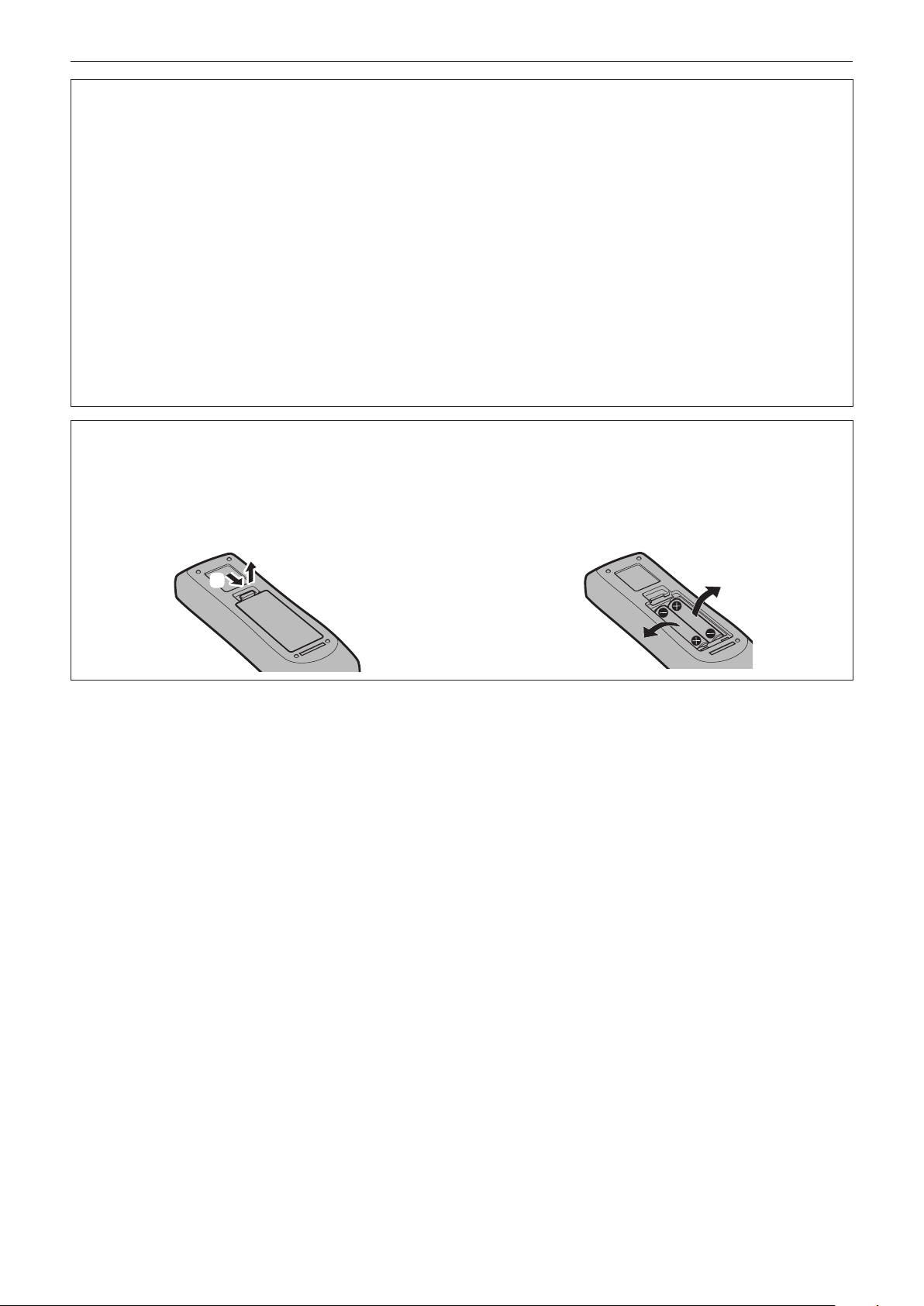
To remove the battery
Remote Control Battery
1. Press the guide and lift the cover.
(ii)
(i)
2. Remove the batteries.
14 - ENGLISH
Page 15

Read this rst!
Brazil Only
Brasil Apenas
rManuseio de baterias usadas
BRASIL
Após o uso, as pilhas e/ou baterias deverão
ser entregues ao estabelecimento comercial
ou rede de assistência técnica autorizada.
Cobrir os terminais positivo (+) e negativo (-) com uma ta isolante adesiva, antes de depositar numa caixa
destinada para o recolhimento. O contato entre partes metálicas pode causar vazamentos, gerar calor, romper
a blindagem e produzir fogo. (Fig. 1)
Fig. 1
Como isolar os terminais
Não desmonte, não remova o invólucro, nem amasse a bateria. O gás liberado pela bateria pode irritar a
garganta, danicar o lacre do invólucro ou o vazamento provocar calor, ruptura da blindagem e produzir fogo
devido ao curto circuito dos terminais. Não incinere nem aqueça as baterias, elas não podem car expostas a
temperaturas superiores a 100 °C (212 °F). O gás liberado pela bateria pode irritar a garganta, danicar o lacre
do invólucro ou o vazamento provocar calor, ruptura da blindagem e produzir fogo devido ao curto circuito dos
terminais provocado internamente.
Evite o contato com o liquido que vazar das baterias. Caso isto ocorra, lave bem a parte afetada com bastante
água. Caso haja irritação, consulte um médico.
Fita Isolante
Fita Isolante
rRemoção das baterias
1. Pressione a guia e levante a tampa.
(ii)
(i)
2. Remova as baterias.
ENGLISH - 15
Page 16

rTrademarks
f SOLID SHINE is a trademark of Panasonic Corporation.
f Panasonic owns patents relating to Light ID technology in Japan and other countries.
f “LinkRay” and the icon are trademarks of Panasonic Corporation.
f Wi-Fi®, Wi-Fi DirectTM and MiracastTM are registered trademarks or trademarks of Wi-Fi Alliance.
f Windows, Internet Explorer and Microsoft Edge are registered trademarks or trademarks of Microsoft
Corporation in the United States and other countries.
f Mac, macOS, and Safari are trademarks of Apple Inc., registered in the United States and other countries.
f PJLinkTM is a registered trademark or pending trademark in Japan, the United States, and other countries and
regions.
f The terms HDMI and HDMI High-Denition Multimedia Interface, and the HDMI Logo are trademarks or
registered trademarks of HDMI Licensing Administrator, Inc. in the United States and other countries.
f Crestron Connected, the Crestron Connected logo, Crestron Fusion, Crestron RoomView, and RoomView are
trademarks or registered trademarks of Crestron Electronics, Inc. in the United States and/or other countries.
f HDBaseTTM is a trademark of HDBaseT Alliance.
f IOS is a trademark or registered trademark of Cisco in the U.S. and other countries and is used under license.
f Android is a trademark of Google Inc.
f QR Code is a registered trademark of DENSO WAVE INCORPORATED in Japan and in other countries.
f Adobe, Adobe Flash Player, and Adobe Reader are trademarks or registered trademarks of Adobe Systems Inc.
in the United States and/or other countries.
f Some of the fonts used in the on-screen menu are Ricoh bitmap fonts, which are manufactured and sold by
Ricoh Company, Ltd.
f This product is licensed under AVC Patent Portfolio License, VC-1 Patent Portfolio License, and MPEG-4 Visual
Patent Portfolio License, and following actions except for the personal or non-prot use are not licensed.
g Recording the image information in compliance with the AVC standard, the VC-1 standard, and the MPEG-4
Visual standard (AVC/VC-1/MPEG-4 video hereafter)
g Playing back the AVC/VC-1/MPEG-4 video recorded by consumer practicing in a private activity, or AVC/VC-1/
MPEG-4 video acquired from the licensed provider
For details, refer to the website of MPEG LA, LLC (http://www.mpegla.com).
f All other names, company names, and product names mentioned in this manual are trademarks or registered
trademarks of their respective owners.
Please note that the ® and TM symbols are not specied in this manual.
rSoftware information regarding this product
This product incorporates the following software:
(1) the software developed independently by or for Panasonic Corporation,
(2) the software owned by third party and licensed to Panasonic Corporation,
(3) the software licensed under the GNU General Public License, Version 2.0 (GPL V2.0),
(4) the software licensed under the GNU LESSER General Public License, Version 2.1 (LGPL V2.1), and/or
(5) open source software other than the software licensed under the GPL V2.0 and/or LGPL V2.1.
The software categorized as (3) - (5) are distributed in the hope that it will be useful, but WITHOUT ANY
WARRANTY, without even the implied warranty of MERCHANTABILITY or FITNESS FOR A PARTICULAR
PURPOSE. Please refer to the detailed terms and conditions thereof shown in the attached CD-ROM.
At least three (3) years from delivery of this product, Panasonic will give to any third party who contacts us at
the contact information provided below, for a charge no more than our cost of physically performing source code
distribution, a complete machine-readable copy of the corresponding source code covered under GPL V2.0, LGPL
V2.1 or the other licenses with the obligation to do so, as well as the respective copyright notice thereof.
Contact Information: oss-cd-request@gg.jp.panasonic.com
rIllustrations in this manual
f Illustrations of the projector, menu screen (OSD), and other parts may vary from the actual product.
f Illustrations displayed on the computer screen may differ depending on the computer type and its operating
system.
f Illustrations of the projector with the power cord attached are only examples. The shape of the supplied power
cords varies depending on the country where you purchased the product.
16 - ENGLISH
Page 17

rReference pages
f Reference pages in this manual are indicated as (x page 00).
rTerm
f In this manual, the “Wireless/wired remote control unit” accessory is referred to as “Remote control”.
ENGLISH - 17
Page 18

Features of the Projector
High picture quality
▶ With a unique optical system which uses
a new-generation laser light source, and
the laser light source drive system, high
luminance of 8 000 lm and high contrast
of 3 000 000:1*1 are achieved even with its
compact size. Also, 4K video signal input is
supported.
*1 When [PICTURE MODE] is set to [DYNAMIC], and
[DYNAMIC CONTRAST] is set to [1] or [2]
Easy and highly exible setup
▶ In addition to the lens replacement method
and equipping of the lens shift, usage
in a wide range of application is made
possible by supporting a wide range of
interfaces such as DIGITAL LINK, and by
supporting the 360° installation utilizing the
characteristics of solid-sate light source.
Quick Steps
For details, refer to the corresponding pages.
1. Set up the projector.
(x page 36)
2. Attach the projection lens.
(x page 50)
3. Connect with external devices.
(x page 52)
4. Connect the power cord.
(x page 58)
5. Switch on the projector.
(x page 60)
Long life and high reliability
▶ The maintenance cost for long-term
operation is reduced by the unique light
source cooling control technology and
improvement of the dust resistance.
6. Make initial settings.
(x page 61)
f Take this step when you switch on the
power for the rst time after purchasing the
projector.
7. Select the input signal.
(x page 67)
8. Adjust the image.
(x page 68)
18 - ENGLISH
Page 19

Chapter 1 Preparation
This chapter describes things you need to know or check before using the projector.
ENGLISH - 19
Page 20

Chapter 1 Preparation — Precautions for use
Precautions for use
Intended use of the product
The product is intended to project still/moving image signals from video equipment and computers onto a screen.
Lens protection material
If you purchased the projector with the standard zoom lens, remove the lens protection material before use, and
store it for the future use. Move the lens position to the home position and attach the lens protection material
when transporting.
If you purchased the projector with the lens sold separately, remove the lens hole cover before use, and store it
for the future use. Move the lens position to the home position, remove the projection lens, and attach the lens
hole cover when transporting.
For the steps to move the lens position to the home position, refer to “Moving the lens position to the home
position” (x page 69).
Lens protection material
Lens hole cover
Cautions when transporting
f When transporting the projector, hold it securely by its bottom and avoid excessive vibration and impacts. They
may damage the internal components and result in malfunctions.
f Do not transport the projector with the adjustable feet extended. Doing so may damage the adjustable feet.
Cautions when installing
rDo not set up the projector outdoors.
The projector is designed for indoor use only.
rDo not set up the projector in the following locations.
f Places where vibration and impacts occur such as in a car or vehicle: Doing so may cause damage to internal
components or malfunction.
f Location close to sea or where corrosive gas may occur: The projector may fall due to corrosion. Also, failure to
do so may shorten the life of the components and result in malfunction.
f Near the exhaust of an air conditioner: Depending on the conditions of use, the screen may uctuate in rare
cases due to the heated air from the air exhaust port or the hot or cooled air from the air conditioner. Make sure
that the exhaust from the projector or other equipment, or the air from the air conditioner does not blow toward
the front of the projector.
f Places with sharp temperature uctuations such as near lights (studio lamps): Doing so may shorten the life of
the light source, or result in deformation of the projector due to heat, which may cause malfunctions.
Follow the operating environment temperature of the projector.
f Near high-voltage power lines or near motors: Doing so may interfere with the operation of the projector.
20 - ENGLISH
Page 21
Chapter 1 Preparation — Precautions for use
rAsk a qualied technician or your dealer for the installation work such as installing to
a ceiling, etc.
To ensure projector performance and safety, ask a qualied technician or your dealer when installing to a ceiling
or in a high place.
rAsk a qualied technician or your dealer to install the cable wiring for DIGITAL LINK
connection.
Image and sound may be disrupted if cable transmission characteristics cannot be obtained due to inadequate
installation.
rThe projector may not work properly due to strong radio wave from the broadcast
station or the radio.
If there is any facility or equipment which outputs strong radio waves near the installation location, install the
projector at a location sufciently far from the source of the radio waves. Or, wrap the LAN cable connected to the
<DIGITAL LINK/LAN> terminal using a piece of metal foil or a metal pipe which is grounded at both ends.
rFocus adjustment
The high clarity projection lens is thermally affected by the light from the light source, making the focus unstable in
the period just after switching on the power. It is recommended that images be projected continuously for at least
30 minutes before the focus is adjusted.
rDo not install the projector at an altitude of 2 700 m (8 858') or higher above sea level.
rDo not use the projector in a location that the ambient temperature exceeds 45 °C
(113 °F).
Using the projector in a location that the altitude is too high or the ambient temperature is too high may reduce the
life of the components or result in malfunctions.
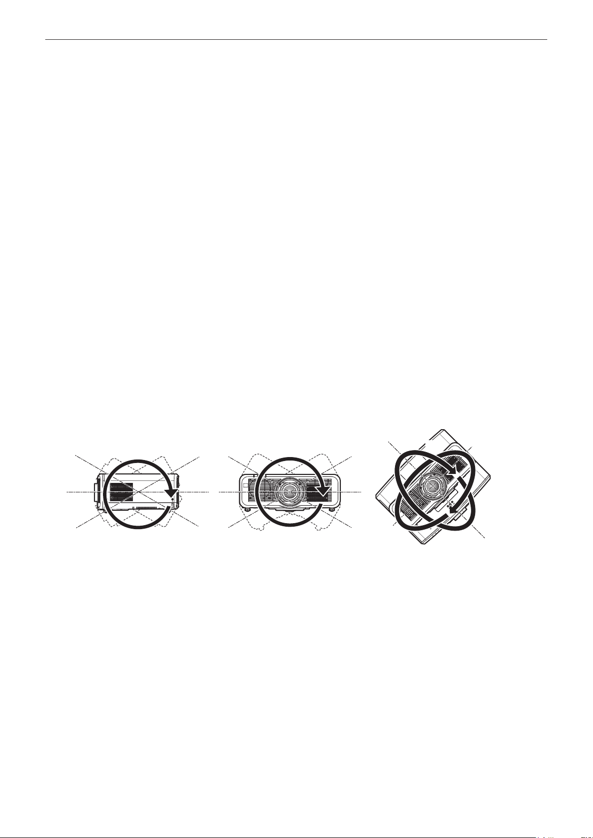
rProjection in all 360° direction is possible.
360°
360° vertically 360° horizontally 360° tilted
360°
(combination of vertical and horizontal)
360°
ENGLISH - 21
Page 22

Chapter 1 Preparation — Precautions for use
rCautions when setting up the projector
f Use the adjustable feet only for the oor standing installation and for adjusting the angle. Using them for other
purposes may damage the projector.
f When installing the projector with a method other than the oor installation using the adjustable feet or the
ceiling installation using the ceiling mount bracket, use the four screw holes for ceiling mount (as shown in the
gure) to x the projector.
In such case, make sure that there is no clearance between the screw holes for ceiling mount on the projector
bottom and the setting surface by inserting spacers (metallic) between them.
f Use a torque screwdriver or Allen torque wrench to tighten the xing screws to their specied tightening torques.
Do not use electric screwdrivers or impact screwdrivers.
(Screw diameter: M6, tapping depth inside the projector: 12 mm (15/32"), screw tightening torque: 4 ± 0.5 N·m)
Adjustable feet
Screw holes for ceiling mount
(M6)
Positions of screw holes for ceiling mount and
adjustable feet
f Do not stack projectors on top of each other.
f Do not use the projector supporting it by the top.
f Do not block the ventilation ports (intake and exhaust) of the projector.
f Prevent hot and cool air from the air conditioning system to blow directly to the ventilation ports (intake and
exhaust) of the projector.
500 mm (19-11/16") or longer 500 mm (19-11/16") or longer
1 000 mm (39-3/8") or longer
100 mm (3-15/16") or longer
f Do not install the projector in a conned space.
When installing the projector in a conned space, provide air conditioning or ventilation separately. Exhaust heat
may accumulate when the ventilation is not enough, triggering the protection circuit of the projector.
22 - ENGLISH
Page 23

Chapter 1 Preparation — Precautions for use
f Panasonic takes no responsibility for any damage to the product caused by an inappropriate choice of location
for installing the projector, even if the warranty period of the product has not expired.
Security
When using this product, take safety measures against the following incidents.
f Personal information being leaked via this product
f Unauthorized operation of this product by a malicious third party
f Interfering or stopping of this product by a malicious third party
Take sufcient security measures.
f Make your password difcult to guess as much as possible.
f Change your password periodically. The password can be set in the [SECURITY] menu → [SECURITY
PASSWORD CHANGE] or the [NETWORK/USB] menu → [Panasonic APPLICATION] → [PASSWORD
CHANGE].
f Panasonic Corporation or its afliate companies will never ask for your password directly. Do not divulge your
password in case you receive such inquiries.
f The connecting network must be secured by a rewall, etc.
f Set a password for the web control and restrict the users who can log in. A password for the web control can be
set in the [Change password] page of the web control screen.
rSecurity when using the wireless LAN product
The advantage of a wireless LAN is that information can be exchanged between a computer or other such
equipment and a wireless access point using radio waves, instead of using a LAN cable, as long as you are within
range for radio transmissions.
On the other hand, because the radio wave can travel through an obstacle (such as a wall) and is accessible from
anywhere within a given range, following problems may occur if security setting is insufcient.
f Transmitted data may be intercepted
A malicious third part may intentionally intercept radio waves and monitor the following transmitted data.
g Personal information such as your ID, password, credit card number
g Content of an Email
f Illegally accessed
A malicious third party may access your personal or corporate network without authorization and engage in the
following types of behavior.
g Retrieve personal and/or secret information (information leak)
g Spread false information by impersonating a particular person (spoong)
g Overwrite intercepted communications and issue false data (tampering)
g Spread harmful software such as a computer virus and crash your data and/or system (system crash)
Since most wireless LAN adapters or access points are equipped with security features to take care of these
problems, you can reduce the possibility of these problems occurring when using this product by making the
appropriate security settings for the wireless LAN device.
Some wireless LAN devices may not be set for security immediately after purchase. To decrease the possibility
of occurrence of security problems, be sure to make all security related settings according to the operation
instructions supplied with each wireless LAN device before using a wireless LAN device.
Depending on the specications of the wireless LAN, a malicious third party may be able to break security settings
by special means.
Panasonic asks customers to thoroughly understand the risk of using this product without making security
settings, and recommends that the customers make security settings at their own discretion and responsibility.
Notes regarding the wireless LAN
Radio wave in the 2.4 GHz/5 GHz band is used when the wireless LAN connection function of the projector is
used. The license of wireless station is not required, but understand the following when using.
To use the wireless LAN function with the projector, it is necessary to attach the optional Wireless Module (Model
No.: ET-WM300).
For details on how to attach the optional Wireless Module (Model No.: ET-WM300), refer to “Attaching the
Wireless Module” (x page 51).
ENGLISH - 23
Page 24

Chapter 1 Preparation — Precautions for use
rDo not use close to other wireless devices.
Following devices may be using radio wave in the same bandwidth as the projector. Using the projector close to
these devices may cause the communication to be disabled or the communication speed to slow down due to
interference of radio wave.
f Microwave oven, etc.
f Industrial, scientic, or medical devices, etc.
f In-plant wireless station for identifying moving vehicles used in the manufacturing lines at a plant
f Specied low power wireless station
rDo not use cell phone, television, or radio as much as possible close to the projector.
Cell phone, television, or radio is using radio wave with different bandwidth from the projector, so there is no effect
on the wireless LAN communication or the send/receive on these devices. However, noise may occur in the audio
or video due to the radio wave from the projector.
rRadio wave for wireless LAN communication does not go through the reinforcing
bars, metal, or concrete.
The projector can communicate through wall or oor made of wood or glass (excluding the glass with metal mesh
embedded), but it cannot communicate through wall or oor made of reinforcing bars, metal, or concrete.
rDo not use the projector as much as possible in a location where static electricity is
generated.
The communication via wireless LAN or wired LAN may be prone to disruption when the projector is used in a
location where static electricity or noise is generated.
There is a rare case that the LAN connection may not be established due to static electricity or noise, so in such
case, turn off the projector, remove the source of problematic static electricity or noise, and turn the projector back
on.
rThis device is restricted to indoor use when operated in the 2.412 to 2.472 GHz band,
in the 5.18 to 5.825 GHz frequency range (Channels 36 to 165).
rUsing the projector outside the country
Note that depending on countries or regions there are restrictions on the channels and frequencies at which you
can use the wireless LAN.
Light ID
Light ID is one of the visible light communication technologies to transfer information with fast speed and stability
using ashing of light. This projector is equipped with a function to transmit the Light ID signal, and following
usage is possible by utilizing the LinkRay Light ID solution service provided by Panasonic.
f By receiving the Light ID signal transmitted by the projector using the camera on a device (smartphone/tablet)
and a dedicated application software, the contents linked to that Light ID signal are acquired and displayed on
the screen of the device.
For details, visit the Panasonic website (https://panasonic.net/cns/LinkRay/).
Note
f A separate contract is necessary to use the LinkRay Light ID solution service.
f The smartphone application software “LinkRay - Light ID Solution” is required.
Search and download “LinkRay” from App Store or Google Play. For the latest information of devices that the operation has
been veried, visit the Panasonic website (https://panasonic.net/cns/LinkRay/).
rNotes regarding Light ID function
f The projected image may icker when the Light ID signal is transmitted, but this is caused luminance change
during the transmission of the Light ID, and it is not a malfunction.
f A striped pattern may generate on the recorded image when the projected image is recorded by a camera, etc.
f The light output will decrease while the Light ID function is used.
f The Light ID signal may become difcult to receive by a device (smartphone/tablet) in following cases.
g When strong light such as outside light is illuminating on the projected screen
g When a Light ID transmitting device other than this projector is installed nearby
g When receiving a signal in a location far from the screen
24 - ENGLISH
Page 25

Chapter 1 Preparation — Precautions for use
g When receiving a signal in a location that is angled against the screen
g When the light reection loss is large due to the screen characteristics
g When the size of the projected image is small
g When the displayed projected image is dark
f When using a laser format bar code reader, take care not to illuminate the bar code reading surface with the
projection light or its reected light. Doing so may cause bar code reader not to read or misread.
f The Light ID function of the projector is not guaranteed to operate on all devices.
DIGITAL LINK
“DIGITAL LINK” is a technology to transmit the video, audio, Ethernet, and serial control signals using a twisted
pair cable by adding unique functions by Panasonic to the HDBaseTTM communication standard formulated by
HDBaseT Alliance.
This projector supports the optional Panasonic DIGITAL LINK output supported device (Model No.: ET‑YFB100G,
ET‑YFB200G) and peripheral devices by other manufacturers (twisted‑pair‑transmitters such as the “XTP
transmitter” of Extron Electronics) based on the same HDBaseTTM standard. For the devices of other
manufacturers that the operation has been veried with this projector, visit the Panasonic website (https://
panasonic.net/cns/projector/). Note that the verication for devices of other manufacturers has been made for the
items set by Panasonic Corporation, and not all the operations have been veried. For operation or performance
problems caused by the devices of other manufacturers, contact the respective manufacturers.
Application software supported by the projector
The projector supports following application software. For details or downloading each application software, visit
the Panasonic website (https://panasonic.net/cns/projector/).
f Logo Transfer Software
This application software transfers the original image, such as company logo, which is projected at the start, to
the projector.
f Smart Projector Control
This application software sets and adjusts the projector connected via LAN using a smartphone or a tablet.
f Multi Monitoring & Control Software
This application software monitors and controls the multiple display devices (projector and at panel display)
connected to an intranet.
f Early Warning Software
This plug-in software monitors the status of the display devices and their peripherals within an intranet, and
noties of abnormality of such equipment and detects the signs of possible abnormality. “Early Warning
Software” is preinstalled in the “Multi Monitoring & Control Software”. To use the early warning function of
this plug‑in software, install “Multi Monitoring & Control Software” in the PC to be used. By enabling the early
warning function, it will notify of the approximate time to replace the consumables for the display devices,
to clean each part of the display devices, and to replace the components of the display devices, allowing to
execute maintenance in advance.
The early warning function can be used by registering maximum of 2048 display devices free of charge for
90 days after installing the “Multi Monitoring & Control Software” into a PC. To continuously use after the 90
days, it is necessary to purchase the license of “Early Warning Software” (ET-SWA100 Series) and perform
the activation. Also, depending on the type of license, the number of display devices that can be registered for
monitoring varies. For details, refer to the Operating Instructions of “Multi Monitoring & Control Software”.
f Wireless Manager ME6.4
This application software transmits the computer screen to the projector via wireless LAN or wired LAN.
Simultaneous projection from one computer to multiple projectors, or simultaneous projection from multiple
computers to one projector is possible.
f Plug and Share
This application software makes it possible to project the computer screen with the projector easily by omitting
the selection of the device when connecting the computer via network by pairing a projector and a computer
using the USB memory.
f Wireless Projector
This application software for iOS/Android is used to project les such as PDF or image by transmitting to the
projector via wireless LAN.
ENGLISH - 25
Page 26

Chapter 1 Preparation — Precautions for use
Storing
To store the projector, store in a dry room.
Disposal
To dispose of the product, ask your local authorities or dealer for correct methods of disposal. Also, dispose of the
product without disassembling.
Cautions on use
rTo get a good picture quality
In order to view a beautiful image in higher contrast, prepare an appropriate environment. Draw curtains or blinds
over windows and turn off any lights near the screen to prevent outside light or light from indoor lamps from
shining onto the screen.
rDo not touch the surface of the projection lens with your bare hands.
If the surface of the projection lens becomes dirty from ngerprints or anything else, this will be magnied and
projected onto the screen.
rLCD panel
The LCD panel is manufactured by a technology with extremely high precision, but there may be missing pixels or
pixels that is constantly illuminated in a rare case. Note that these phenomenon are not malfunction.
Also, a residual image may remain in the image of the LCD panel when a still image is projected for long time, and
in such case, project a full white image for 1 hour or longer. Note that the residual image may not be completely
erased.
rOptical parts
The replacement cycle for the optical parts such as the LCD panel or polarization plate may become shorter even
if it is used for less than one year when the ambient temperature is high or in an environment with large amount of
dust or cigarette smoke. For details, consult your dealer.
rLight source
The light source of the projector uses lasers, and has the following characteristics.
f Depending on the operating environment temperature, the luminance of the light source will decrease.
The higher the temperature becomes, the more the luminance of the light source decreases.
f The luminance of the light source will decrease by duration of usage.
If brightness is noticeably reduced and the light source does not turn on, ask your dealer to clean inside the
projector or replace the light source unit.
rComputer and external device connections
When connecting a computer or an external device, read this manual carefully regarding the use of power cords
and shielded cables as well.
26 - ENGLISH
Page 27
Chapter 1 Preparation — Precautions for use
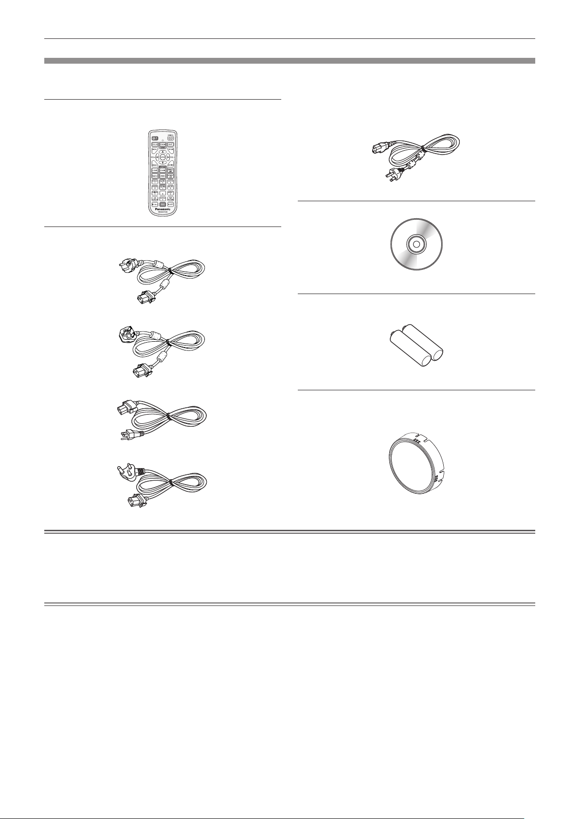
Accessories
Make sure that the following accessories are provided with your projector. Numbers enclosed in < > show the
number of accessories.
Wireless/wired remote control unit <1>
(N2QAYA000150)
Power cord
(TXFSX01RXQZ)
(TXFSX01RXRZ)
(TXFSX03VARZ)
For Taiwan
(1JP1RZ970) <1>
CD-ROM <1>
(Operating Instructions are included.)
AAA/R03 or AAA/LR03 battery <2>
(For remote control unit)
Lens cover <1>
(Only for models with lens)
(6103626291)
(TXFSX02UTRZ)
Attention
f After unpacking the projector, discard the power cord cap and packaging material properly.
f Do not use the supplied power cord for devices other than this projector.
f For missing accessories, consult your dealer.
f Store small parts in an appropriate manner, and keep them away from small children.
Note
f The type and number of the supplied power cords vary depending on the country or region where you purchased the
product.
f The model numbers of accessories are subject to change without prior notice.
ENGLISH - 27
Page 28

Chapter 1 Preparation — Precautions for use
Optional accessories
Optional accessories (product name) Model No.
Projection lens
Zoom Lens
Fixed-focus Lens ET-ELW21
Ceiling Mount Bracket
Early Warning Software
(Basic license/3‑year license)
Digital Interface Box ET‑YFB100G
DIGITAL LINK Switcher ET‑YFB200G
Replacement Filter Unit ET-RFM100
Wireless Module ET-WM300
*1 This product is equivalent to the lens attached to the projector models with standard zoom lens. The availability of this product
varies depending on the country. For details, contact your dealer.
*2 When the projector is mounted to the existing Ceiling Mount Bracket (in combination with the Model No.: ET‑PKD120H (for High
Ceilings) or ET‑PKD120S (for Low Ceilings), and the Model No.: ET‑PKE300B (Projector Mount Bracket)), it is necessary to
replace the drop-prevention wire rope with the one corresponding to this projector. Consult your dealer.
Drop-prevention set (service model no.: DPPW1004ZA/X1)
*3 The sufx of the Model No. differs according to the license type.
*4 The availability of this product varies depending on the country. For details, contact your dealer.
ET-ELW20, ET-ELT22, ET-ELS20*1, ET-ELT23, ET-ELW22
ET-PKD120H (for High Ceilings)
ET-PKD120S (for Low Ceilings)
ET‑PKE301B (Projector Mount Bracket)
ET-SWA100 Series
*4
*3
*2
Note
f The model numbers of optional accessories are subject to change without prior notice.
28 - ENGLISH
Page 29
Chapter 1 Preparation — About your projector
About your projector
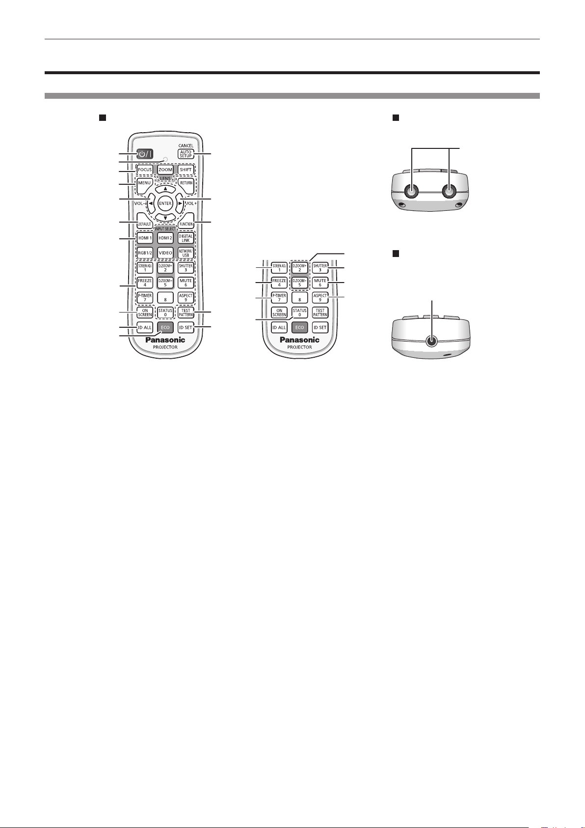
Remote control
Front Top
1
2
3
4
5
6
7
8
9
10
11
1 Power <v/b> button
(v: Standby, b: Power on)
Sets the projector to the state where the projector is turned
off (standby mode) when the <MAIN POWER> switch on the
projector is set to <ON> and in projection mode.
Sets the projector to projection mode when the power is
switched off (standby mode).
2 Remote control indicator
Blinks if any button in the remote control is pressed.
3 Lens buttons (<FOCUS>, <ZOOM>, <SHIFT>)
Adjusts the focus, zoom, and lens shift of the lens.
(x page 68)
4 <MENU> button/<RETURN> button/<ENTER> button/
asqw buttons
Used to navigate through the menu screen. (x page 80)
asqw buttons are also used to enter the password in
[SECURITY] or enter characters.
5 <VOL-> button/<VOL+> button
Adjusts the volume of the built-in speaker and the audio output.
(x page 73)
6 <DEFAULT> button
Resets the content of the displayed sub-menu to the factory
default. (x page 81)
7 Input selection buttons (<HDMI 1>, <HDMI 2>, <DIGITAL
LINK>, <RGB1/2>, <VIDEO>, <NETWORK/USB>)
Switches the input signal to project. (x page 67)
8 Number (<0> - <9>) buttons
Used for entering an ID number or a password in a multiple
projector environment.
9 <ON SCREEN> button
Switches the on-screen display function on (display) or off
(hide). (x page 73)
10 <ID ALL> button
Used to simultaneously control all the projectors with a
single remote control in a multiple projector environment.
(x page 34)
11 <ECO> button
Displays the setting screen relating to ECO management. (x
pages 77, 114 )
12
13
14
15
5
16
17
18
19
24
20
21
22
23
12 <AUTO SETUP/CANCEL> button
Automatically adjusts the image display position while projecting
the image.
[PROGRESS] is displayed while in automatic adjustment.
(x page 74)
Also used for cancel operation during digital zoom and the
operation of the Memory Viewer screen, or while the standby
screen for Panasonic APPLICATION input is displayed.
During MIRRORING input, the receiving device name and the
URL to access the projector are displayed at the top left of the
screen. (x page 184)
13 <FUNCTION> button
Assigns a frequently used operation as a shortcut button.
(x page 76)
14 <TEST PATTERN> button
Displays the test pattern. (x page 76)
15 <ID SET> button
Sets the ID number of the remote control in a multiple projector
environment. (x page 34)
16 <SCREEN ADJ> button
Used to correct the distortion of the projected image. (x pages
74, 94)
17 <FREEZE> button
Used when pausing the image and turning off the audio.
(x page 73)
18 <P-TIMER> button
Operates the presentation timer function. (x page 76)
19 <STATUS> button
Displays the projector information.
20 <D.ZOOM+> button/<D.ZOOM-> button
Enlarges or reduces the image. (x page 75)
21 <SHUTTER> button
Used when temporarily turning off the image and audio.
(x page 72)
22 <MUTE> button
Used when temporarily turning off the audio. (x page 72)
23 <ASPECT> button
Switches the aspect ratio of the image. (x page 76)
24 Remote control signal transmitter
Bottom
25
ENGLISH - 29
Page 30

Chapter 1 Preparation — About your projector
25 Remote control wired terminal
This is a terminal used to connect to the projector via a cable
when the remote control is used as a wired remote control.
(x page 34)
Attention
f Do not drop the remote control.
f Avoid contact with liquids or moisture.
f Do not attempt to modify or disassemble the remote control.
f Observe the following instructions that are indicated on the caution label at the back of the remote control:
g Do not use old battery with new one.
g Do not use batteries other than the type specied.
g Be sure the batteries are inserted properly.
For other instructions, read the instructions related to batteries that are described in “Read this rst!”.
Caution label at the back of the remote control
Note
f When operating the remote control by directly pointing at the remote control signal receiver of the projector, operate the remote control
within a distance approximately 30 m (98'5") from the remote control signal receiver. The remote control can control at angles of up to ±30°
vertically and horizontally, but the effective control range may be reduced.
f If there are any obstacles between the remote control and the remote control signal receiver, the remote control may not operate properly.
f The signal will be reected off the screen. However, the operating range may be limited from light reection loss due to the screen material.
f If the remote control signal receiver directly receives strong light, such as uorescent light, the remote control may not operate properly. Use
it in a place distant from the light source.
f The power indicator <ON (G)/STANDBY (R)> will blink if the projector receives a remote control signal.
30 - ENGLISH
Page 31

Projector body
Chapter 1 Preparation — About your projector
Front
1 2 3
7
Rear
5
4
8
9
11 12 13 14 815
10 9
Side
6
16
8
88
17 18 19
Projection direction
1 Remote control signal receiver (front)
2 Power indicator <ON (G)/STANDBY (R)>
Indicates the status of the power.
3 Light source indicator <LIGHT>
Indicates the status of the light source.
4 Temperature indicator <TEMP>
Indicates the internal temperature status.
5 Filter indicator <FILTER>
Indicates the status of the air lter unit.
6 Projection lens
7 Adjustable feet
Adjusts the projection angle.
8 Air intake port
BottomTop
20
9 Air exhaust port
10 Connecting terminals (x page 33)
11 Remote control signal receiver (rear)
12 <MAIN POWER> switch
Turns on/off the main power.
13 <AC IN> terminal
Connect the supplied power cord.
14 Speaker
15 Security slot
This security slot is compatible with the Kensington security
cables.
16 Air lter cover
There is the air lter unit inside.
ENGLISH - 31
Page 32

Chapter 1 Preparation — About your projector
17 Luminance sensor (x page 88)
18 Control panel (x page 32)
19 Top slide cover
20 Burglar hook port
Attention
f Do not block the ventilation ports (intake and exhaust) of the projector.
The components may deteriorate faster if cooling inside the projector is inhibited.
r Control panel
1
2
3
4
5
1 Power <v/b> button
(v: Standby, b: Power on)
Sets the projector to the state where the projector is turned
off (standby mode) when the <MAIN POWER> switch on the
projector is set to <ON> and in projection mode.
Sets the projector to projection mode when the power is
switched off (standby mode).
2 <MENU> button
Displays or hides the main menu. (x page 80)
Returns to the previous menu when a sub-menu is displayed.
3 <VOL-> button/<VOL+> button
Adjusts the volume of the built-in speaker and the audio output.
(x page 73)
4 <SHUTTER> button
Used to turn off the image and audio temporarily. (x page 72)
5 <ENTER> button
6 <INPUT SELECT> button
7 <LENS/CANCEL> button
8 asqw buttons
There is the wireless module connection terminal inside.
(x page 51)
Attaches a burglar prevention cable, etc.
6
3
7
8
Determines and executes an item in the menu screen.
Switches the input signal to project. (x page 67)
Adjusts the focus, zoom, and lens shift of the lens.
(x page 68)
Also used for cancel operation during digital zoom and
operation in the Memory Viewer screen, or while the standby
screen for MIRRORING input or Panasonic APPLICATION input
is displayed.
Selects an item in the menu screen, changes the setting, and
adjusts the level.
Also used to enter a password in the [SECURITY] menu or
enter characters.
32 - ENGLISH
Page 33

r Connecting terminals
Chapter 1 Preparation — About your projector
1 2 3 4 5 86 7
129 10 11 13 14 15
1 <DC OUT> terminal
This is the USB terminal only used for power supply. (DC 5 V,
maximum 2.0 A)
This can be used when the projector is in projecting status and
when power is to be supplied to the wireless display adapter,
etc.
2 <RGB 1 IN> terminals (<G/Y>, <B/PB>, <R/PR>, <SYNC/HD>,
<VD>)
This is a terminal to input the RGB signal or YCBCR/YPBPR
signal.
3 <VIEWER/PAIRING> terminal
This is a terminal to connect the USB memory when using
the Memory Viewer function, pairing function, or data cloning
function. (x pages 186, 195)
4 <LAN> terminal
This is the LAN terminal to connect to the network.
This also supports the image transfer from the image transfer
application software. (x page 154)
5 <RGB 2 IN> terminal
This is a terminal to input the RGB signal or YCBCR/YPBPR
signal.
6 <DIGITAL LINK/LAN> terminal
This is a terminal to connect a device that transmits video
signal or audio signal via the LAN terminal. Also, this is the LAN
terminal to connect to the network.
7 <VIDEO IN> terminal
This is a terminal to input video signal.
8 <HDMI 1 IN> terminal/<HDMI 2 IN> terminal
This is a terminal to input the HDMI signal.
9 <REMOTE 1 IN> terminal
This is a terminal to remotely control the projector using the
external control circuit.
10 <MONITOR OUT> terminal
This is a terminal to output the RGB signal or the YCBCR/
YPBPR signal input in the <RGB 1 IN> terminal or the <RGB 2
IN> terminal. When the input is switched to RGB1 or RGB2,
corresponding input signal is output.
11 <SERIAL IN> terminal
This is the RS-232C compatible terminal to externally control
the projector by connecting a computer.
12 <AUDIO IN 1> terminal/<AUDIO IN 2> terminal
This is a terminal to input audio.
13 <AUDIO IN 3> terminal
This is a terminal to input audio signal. There are right input
<R> and left input <L>.
14 <VARIABLE AUDIO OUT> terminal
This is a terminal to output the audio signal input to the
projector.
15 <REMOTE 2 IN> terminal
This is a terminal to connect the remote control with a cable
when controlling the projector with a wired remote control.
Attention
f When a LAN cable is directly connected to the projector, the network connection must be made indoors.
The signal may deteriorate due to the effect of noise or cable length.
f The <DIGITAL LINK/LAN> terminal and the <LAN> terminal are connected inside the projector. When using both the <DIGITAL LINK/
LAN> terminal and the <LAN> terminal, congure the system to prevent them from being connected to the same network directly or via the
peripheral devices such as a hub or twisted-pair-cable transmitter.
ENGLISH - 33
Page 34

Chapter 1 Preparation — Preparing the remote control
Preparing the remote control
Inserting and removing the batteries
(i)
1) Open the cover. (Fig. 1)
2) Insert the batteries and close the cover (insert the m side first). (Fig. 2)
f When removing the batteries, perform the steps in reverse order.
(ii)
Fig. 1 Fig. 2
When using the multiple projectors
When you use the multiple projectors together, you can operate all the projectors simultaneously or each projector
individually using single remote control, if a unique ID number is assigned to each projector.
When using the projectors by setting the ID numbers, set the ID number of the projector body after initial settings
have been completed. Then, set the ID number of the remote control. For initial settings, refer to “When the initial
setting screen is displayed” (x page 61).
The factory default ID number of the projector (projector body and remote control) is set to [ALL], so you can use
it as it is. Set the ID numbers of the projector body and remote control as necessary.
For details on setting the ID number of the remote control, refer to “Setting ID number of the remote control”
(x page 77).
Note
f Set the ID number of the projector body from the [PROJECTOR SETUP] menu → [PROJECTOR ID].
Connecting the remote control to the projector with a cable
To control the projector with a wired remote control, connect the remote control wired terminal of the remote
control with the <REMOTE 2 IN> terminal of the projector with commercially available M3 stereo mini plug cable.
This is effective when using the projector in location where there is an obstacle between the projector and the
remote control or location that is affected by the outside light.
f The wireless remote control cannot be used when a cable is connected to the <REMOTE 2 IN> terminal of the
projector.
M3 stereo mini jack cable (commercially
available)
Remote control
Connecting to the remote control wired terminal
Connecting terminals
Attention
f Use a cable that is 15 m (49'3") or shorter, with 2 core shielded. The remote control may not operate when the length of the cable exceeds
15 m (49'3") or when the shielding of the cable is inadequate.
34 - ENGLISH
Page 35

Chapter 2 Getting Started
This chapter describes things you need to do before using the projector such as the setup and connections.
ENGLISH - 35
Page 36

Chapter 2 Getting Started — Setting up
Setting up
Installation mode
The installation modes of the projector are as follows. Set [FRONT/REAR]/[FLOOR/CEILING] in the
[PROJECTOR SETUP] menu → [PROJECTION METHOD] (x page 113) depending on the installation mode.
Setting on a desk/oor and projecting forward Setting on a desk/oor and projecting from rear
(Using the translucent screen)
Menu item Setting value Menu item Setting value
[FRONT/REAR]
[FLOOR/CEILING]
Mounting on the ceiling and projecting forward Mounting on the ceiling and projecting from rear
[FRONT]
[AUTO] or [FLOOR]
(Using the translucent screen)
[FRONT/REAR]
[FLOOR/CEILING]
[REAR]
[AUTO] or [FLOOR]
Menu item Setting value Menu item Setting value
[FRONT/REAR]
[FLOOR/CEILING]
Portrait setting and projecting forward Portrait setting and projecting from rear
Menu item Setting value Menu item Setting value
[FRONT/REAR]
[FLOOR/CEILING]
Set in accordance with the image
to project.
[FRONT]
[AUTO] or [CEILING]
(Using the translucent screen)
[FRONT]
[FRONT/REAR]
[FLOOR/CEILING]
[FRONT/REAR]
[FLOOR/CEILING]
[REAR]
[AUTO] or [CEILING]
[REAR]
Set in accordance with the image
to project.
Note
f In the portrait setting, the on-screen menu is displayed sideways.
To display the on-screen menu vertically, go to the [DISPLAY OPTION] menu → [ON-SCREEN DISPLAY] (x page 106) and change the
[OSD ROTATION] setting.
f The projector has a built-in angle sensor. The attitude of the projector is automatically detected by setting [FLOOR/CEILING] to [AUTO] in
the [PROJECTOR SETUP] menu → [PROJECTION METHOD].
36 - ENGLISH
Page 37

Chapter 2 Getting Started — Setting up
r Angle sensor
The range of the installation attitude that is detected by the angle sensor built-in the projector is as follows.
Floor standing installation
30°
30°
Floor standing installation
Projection direction
Ceiling mount installation
Parts for installation (optional)
The optional Ceiling Mount Bracket is required. The Ceiling Mount Bracket (Model No.: ET-PKD120H (for
High Ceilings) or ET-PKD120S (for Low Ceilings)) is used together with the Ceiling Mount Bracket (Model No.:
ET-PKE301B (Projector Mount Bracket)).
Model No.: ET‑PKD120H (for High Ceilings), ET‑PKD120S (for Low Ceilings), ET‑PKE301B (Projector
Mount Bracket)
When the projector is mounted to the existing Ceiling Mount Bracket (in combination with the Model No.:
ET-PKD120H (for High Ceilings) or ET-PKD120S (for Low Ceilings), and the Model No.: ET-PKE300B (Projector
Mount Bracket)), it is necessary to replace the drop-prevention wire rope with the one corresponding to this
projector. Consult your dealer.
Drop‑prevention set (service model no.: DPPW1004ZA/X1)
f Be sure to use the Ceiling Mount Bracket specied for this projector.
f Refer to the Installation Instructions of the Ceiling Mount Bracket when installing and setting up the projector.
Attention
f To ensure projector performance and security, installation of the Ceiling Mount Bracket must be carried out by your dealer or a qualied
technician.
ENGLISH - 37
Page 38

Chapter 2 Getting Started — Setting up
Projected image and throw distance
Install the projector referring to the projected image size and projection distance. Image size and image position
can be adjusted in accordance with the screen size and screen position.
f Following illustration is prepared on the assumption that the projected image size and position have been
aligned to t full in the screen.
Projected image
SH
L (LW/LT)
*1 LW: Minimum projection distance when the Zoom Lens is used
LT: Maximum projection distance when the Zoom Lens is used
Projection lens Model No. Dimension for L1 (approximate value)
Standard zoom lens / ET-ELS20
*1
L1 Lens protrusion dimension
SH Projected image height
SW Projected image width
H Distance from the lens center to the bottom edge of the projected image
SD Projected image size
ET-ELW21 0.005
ET-ELW22 0.050
ET-ELW20 0.035
ET-ELT22
ET-ELT23
SD
SW
Projection distance
SW SH
H
Screen
Screen
L1
L (LW/LT)
L1
L (LW/LT)
(Unit: m)
0.015
0.036
0.032
Attention
f Before setting up, read “Precautions for use” (x page 20).
f Do not use the projector and the high-power laser equipment in the same room. The LCD panel may be damaged if a laser beam hits the
projection lens surface.
38 - ENGLISH
Page 39

Chapter 2 Getting Started — Setting up
[SCREEN ADJUSTMENT] projection range
[VERTICAL KEYSTONE] (viewed from the side) [HORIZONTAL KEYSTONE] (viewed from above)
Screen
Vertical arc correction (viewed from the side) Horizontal arc correction (viewed from above)
Projection distance
Arc radius
Screen
Screen
Projection distance
Arc radius
Screen
Arc center
Screen
Projection distance
Arc radius
Arc center
Screen
Projection distance
Arc radius
ENGLISH - 39
Page 40

PT‑MZ770
Chapter 2 Getting Started — Setting up
[KEYSTONE] and [CURVED CORRECTION] used
Only [KEYSTONE] used
Projection lens
Model No.
Standard zoom
lens/ET-ELS20
ET-ELW21 ±22 ±15 ±8 ±8 1.7 4.3 1.0 2.6
ET-ELW22 ±22 ±15 ±8 ±8 1.7 4.3 1.0 2.6
ET-ELW20 ±25 ±30 ±20 ±15 1.2 3.1 0.7 1.8
ET-ELT22 ±25 ±30 ±20 ±15 0.6 1.1 0.3 0.6
ET-ELT23 ±25 ±30 ±20 ±15 0.4 0.7 0.2 0.4
*1 When [VERTICAL KEYSTONE] and [HORIZONTAL KEYSTONE] are used simultaneously, correction cannot be made exceeding total of 55°.
Vertical
keystone
correction
angle α (°)
±25 ±30 ±20 ±15 0.9 1.8 0.5 1.0
Horizontal
keystone
correction
angle β (°)
*1
Vertical
keystone
correction
angle α (°)
together
Horizontal
keystone
correction
angle β (°)
Min. value
of R2/L2
Min. value
of R3/L3
Only [CURVED
CORRECTION] used
Min. value
of R2/L2
Min. value
of R3/L3
PT‑MW730
[KEYSTONE] and [CURVED CORRECTION] used
Only [KEYSTONE] used
Projection lens
Model No.
Standard zoom
lens/ET-ELS20
ET-ELW21 ±22 ±15 ±8 ±8 1.7 4.3 1.0 2.6
ET-ELW22 ±22 ±15 ±8 ±8 1.7 4.3 1.0 2.6
ET-ELW20 ±35 ±35 ±20 ±15 1.2 3.1 0.7 1.8
ET-ELT22 ±35 ±35 ±20 ±15 0.6 1.1 0.3 0.6
ET-ELT23 ±35 ±35 ±20 ±15 0.4 0.7 0.2 0.4
Vertical
keystone
correction
angle α (°)
±35 ±35 ±20 ±15 0.9 1.8 0.5 1.0
Horizontal
keystone
correction
angle β (°)
*1
Vertical
keystone
correction
angle α (°)
together
Horizontal
keystone
correction
angle β (°)
Min. value
for R2/L2
Min. value
for R3/L3
Only [CURVED
CORRECTION] used
Min. value
for R2/L2
Min. value
for R3/L3
*1 When [VERTICAL KEYSTONE] and [HORIZONTAL KEYSTONE] are used simultaneously, correction cannot be made exceeding total of 55°.
Note
f When [SCREEN ADJUSTMENT] is used, the focus of the entire screen may be lost as correction increases.
f Make the curved screen a circular arc shape with one part of a perfect circle removed.
40 - ENGLISH
Page 41

Chapter 2 Getting Started — Setting up
Projection distance of each projection lens
A ±5 % error in listed projection distances may occur.
When [SCREEN ADJUSTMENT] is used, distance is corrected to become smaller than the specied image size.
PT‑MZ770
r When the screen aspect ratio is 16:10
(Unit: m)
Fixed‑
Lens type Zoom Lens
Projection lens Model No.
Throw ratio
Projected image size Projection distance (L)
Diagonal (SD)
1.016 (40") 0.538 0.862 1.36 2.35 ― ― 1.02 1.41 2.29 3.81 3.72 6.03 0.63
1.270 (50") 0.673 1.077 1.71 2.95 ― ― 1.29 1.77 2.89 4.79 4.70 7.59 0.80
1.524 (60") 0.808 1.292 2.06 3.55 1.00 1.26 1.55 2.14 3.49 5.77 5.68 9.15 0.97
1.778 (70") 0.942 1.508 2.42 4.15 1.18 1.48 1.82 2.50 4.09 6.75 6.66 10.71 1.14
2.032 (80") 1.077 1.723 2.77 4.76 1.35 1.69 2.09 2.87 4.69 7.73 7.64 12.27 1.32
2.286 (90") 1.212 1.939 3.12 5.36 1.53 1.91 2.36 3.23 5.30 8.71 8.63 13.83 1.49
2.540 (100") 1.346 2.154 3.48 5.96 1.71 2.13 2.63 3.60 5.90 9.69 9.61 15.39 1.66
3.048 (120") 1.615 2.585 4.18 7.16 2.06 2.56 3.16 4.33 7.10 11.65 11.57 18.51 2.00
3.810 (150") 2.019 3.231 5.24 8.96 2.58 3.22 3.97 5.42 8.90 14.59 14.52 23.19 2.52
5.080 (200") 2.692 4.308 7.01 11.96 3.46 4.30 5.31 7.25 11.91 19.49 19.43 30.99 3.38
6.350 (250") 3.365 5.385 8.77 14.96 4.34 5.39 6.65 9.07 14.91 24.39 24.34 38.79 4.24
7.620 (300") 4.039 6.462 10.54 17.97 5.21 6.48 7.99 10.90 17.92 29.29 29.25 46.59 5.10
8.890 (350") 4.712 7.539 12.30 20.97 6.09 7.56 9.33 12.73 20.92 34.19 34.16 54.39 5.95
10.160 (400") 5.385 8.616 14.07 23.97 6.97 8.65 10.67 14.55 23.93 39.09 39.07 62.19 6.81
*1
Height
(SH)
Width
(SW)
Standard zoom
lens/ET‑ELS20
1.61‑2.76:1 0.786‑0.983:1 1.21‑1.66:1 2.72‑4.48:1 4.44‑7.12:1 0.764:1
Min.
(LW)
Max.
(LT)
ET‑ELW22 ET‑ELW20
Min.
(LW)
Max.
(LT)
Min.
(LW)
Max.
(LT)
ET‑ELT22 ET‑ELT23
Min.
(LW)
Max.
(LT)
Min.
(LW)
Max.
(LT)
focus
Lens
ET‑ELW21
Fixed
Projection lens Model No.
Projected image size
Diagonal (SD)
1.016 (40") 0.538 0.862
1.270 (50") 0.673 1.077
1.524 (60") 0.808 1.292
1.778 (70") 0.942 1.508
2.032 (80") 1.077 1.723
2.286 (90") 1.212 1.939
2.540 (100") 1.346 2.154
3.048 (120") 1.615 2.585
3.810 (150") 2.019 3.231
5.080 (200") 2.692 4.308
6.350 (250") 3.365 5.385
7.620 (300") 4.039 6.462
8.890 (350") 4.712 7.539
10.160 (400") 5.385 8.616
*1 The throw ratio is based on the value during projection of 2.03 m (80") projected image size.
*2 When the Fixed-focus Lens (Model No.: ET-ELW21) is attached, the lens shift is not possible, therefore the height position (H) becomes SH/2.
Height
(SH)
Width
(SW)
Standard zoom lens/
ET‑ELS20/ET‑ELW20/
ET‑ELT22/ET‑ELT23
-
0.09 - 0.63 ― 0.27
-
0.11 - 0.79 ― 0.34
-
0.14 - 0.95
-
0.16 - 1.10
-
0.18 - 1.26
-
0.21 - 1.42
-
0.23 - 1.58
-
0.27 - 1.89
-
0.34 - 2.36
-
0.46 - 3.15
-
0.57 - 3.94
-
0.69 - 4.73
-
0.80 - 5.51
-
0.92 - 6.30
ET‑ELW22
Height position (H)
-
0.08 - 0.89 0.40
-
0.09 - 1.04 0.47
-
0.11 - 1.18 0.54
-
0.12 - 1.33 0.61
-
0.13 - 1.48 0.67
-
0.16 - 1.78 0.81
-
0.20 - 2.22 1.01
-
0.27 - 2.96 1.35
-
0.34 - 3.70 1.68
-
0.40 - 4.44 2.02
-
0.47 - 5.18 2.36
-
0.54 - 5.92 2.69
*2
ET‑ELW21
(Fixed)
ENGLISH - 41
Page 42

Chapter 2 Getting Started — Setting up
r When the screen aspect ratio is 16:9
(Unit: m)
Fixed‑
Lens type Zoom Lens
Projection lens Model No.
Throw ratio
Projected image size Projection distance (L)
Diagonal (SD)
1.016 (40") 0.498 0.886 1.40 2.42 ― ― 1.05 1.45 2.36 3.92 3.83 6.20 0.65
1.270 (50") 0.623 1.107 1.76 3.04 ― ― 1.32 1.82 2.97 4.92 4.83 7.81 0.83
1.524 (60") 0.747 1.328 2.12 3.65 1.03 1.30 1.60 2.20 3.59 5.93 5.84 9.41 1.00
1.778 (70") 0.872 1.550 2.49 4.27 1.21 1.52 1.87 2.57 4.21 6.94 6.85 11.01 1.18
2.032 (80") 0.996 1.771 2.85 4.89 1.39 1.74 2.15 2.95 4.83 7.95 7.86 12.62 1.35
2.286 (90") 1.121 1.992 3.21 5.51 1.57 1.97 2.43 3.32 5.45 8.95 8.87 14.22 1.53
2.540 (100") 1.245 2.214 3.57 6.12 1.75 2.19 2.70 3.70 6.06 9.96 9.88 15.82 1.71
3.048 (120") 1.494 2.657 4.30 7.36 2.11 2.64 3.25 4.45 7.30 11.97 11.90 19.03 2.06
3.810 (150") 1.868 3.321 5.39 9.21 2.66 3.31 4.08 5.58 9.15 15.00 14.93 23.84 2.59
5.080 (200") 2.491 4.428 7.20 12.29 3.56 4.42 5.46 7.45 12.24 20.03 19.98 31.86 3.47
6.350 (250") 3.113 5.535 9.02 15.38 4.46 5.54 6.83 9.33 15.33 25.07 25.02 39.87 4.36
7.620 (300") 3.736 6.641 10.83 18.47 5.36 6.66 8.21 11.20 18.42 30.10 30.07 47.89 5.24
8.890 (350") 4.358 7.748 12.65 21.55 6.26 7.77 9.59 13.08 21.51 35.14 35.12 55.91 6.12
10.160 (400") 4.981 8.855 14.46 24.64 7.16 8.89 10.97 14.96 24.60 40.18 40.17 63.92 7.00
*1
Height
(SH)
Width
(SW)
Standard zoom
lens/ET‑ELS20
1.61‑2.76:1 0.787‑0.984:1 1.21‑1.66:1 2.73‑4.49:1 4.44‑7.12:1 0.765:1
Min.
(LW)
Max.
(LT)
ET‑ELW22 ET‑ELW20
Min.
(LW)
Max.
(LT)
Min.
(LW)
Max.
(LT)
ET‑ELT22 ET‑ELT23
Min.
(LW)
Max.
(LT)
Min.
(LW)
Max.
(LT)
focus
Lens
ET‑ELW21
Fixed
Projection lens Model No.
Projected image size
Diagonal (SD)
1.016 (40") 0.498 0.886
1.270 (50") 0.623 1.107
1.524 (60") 0.747 1.328
1.778 (70") 0.872 1.550
2.032 (80") 0.996 1.771
2.286 (90") 1.121 1.992
2.540 (100") 1.245 2.214
3.048 (120") 1.494 2.657
3.810 (150") 1.868 3.321
5.080 (200") 2.491 4.428
6.350 (250") 3.113 5.535
7.620 (300") 3.736 6.641
8.890 (350") 4.358 7.748
10.160 (400") 4.981 8.855
*1 The throw ratio is based on the value during projection of 2.03 m (80") projected image size.
*2 When the Fixed-focus Lens (Model No.: ET-ELW21) is attached, the lens shift is not possible, therefore the height position (H) becomes SH/2.
Height
(SH)
Width
(SW)
Standard zoom lens/
ET‑ELS20/ET‑ELW20/
ET‑ELT22/ET‑ELT23
-
0.12 - 0.62 ― 0.25
-
0.15 - 0.77 ― 0.31
-
0.18 - 0.93
-
0.21 - 1.08
-
0.24 - 1.24
-
0.27 - 1.39
-
0.30 - 1.55
-
0.37 - 1.86
-
0.46 - 2.32
-
0.61 - 3.10
-
0.76 - 3.87
-
0.91 - 4.65
-
1.07 - 5.42
-
1.22 - 6.20
ET‑ELW22
Height position (H)
-
0.12 - 0.87 0.37
-
0.15 - 1.02 0.44
-
0.17 - 1.16 0.50
-
0.19 - 1.31 0.56
-
0.21 - 1.45 0.62
-
0.25 - 1.74 0.75
-
0.31 - 2.18 0.93
-
0.42 - 2.91 1.25
-
0.52 - 3.63 1.56
-
0.62 - 4.36 1.87
-
0.73 - 5.08 2.18
-
0.83 - 5.81 2.49
*2
ET‑ELW21
(Fixed)
42 - ENGLISH
Page 43

Chapter 2 Getting Started — Setting up
r When the screen aspect ratio is 4:3
(Unit: m)
Fixed‑
Lens type Zoom Lens
Projection lens Model No.
Throw ratio
Projected image size Projection distance (L)
Diagonal (SD)
1.016 (40") 0.610 0.813 1.54 2.67 ― ― 1.16 1.60 2.61 4.33 4.24 6.85 0.72
1.270 (50") 0.762 1.016 1.94 3.35 ― ― 1.46 2.01 3.29 5.43 5.35 8.62 0.91
1.524 (60") 0.914 1.219 2.34 4.03 1.14 1.43 1.77 2.43 3.97 6.54 6.46 10.39 1.11
1.778 (70") 1.067 1.422 2.74 4.71 1.34 1.68 2.07 2.84 4.65 7.65 7.57 12.15 1.30
2.032 (80") 1.219 1.626 3.14 5.39 1.54 1.92 2.37 3.25 5.33 8.76 8.68 13.92 1.50
2.286 (90") 1.372 1.829 3.54 6.07 1.74 2.17 2.68 3.67 6.01 9.87 9.79 15.68 1.69
2.540 (100") 1.524 2.032 3.94 6.75 1.94 2.42 2.98 4.08 6.69 10.98 10.91 17.45 1.89
3.048 (120") 1.829 2.438 4.74 8.11 2.33 2.91 3.59 4.91 8.05 13.20 13.13 20.98 2.28
3.810 (150") 2.286 3.048 5.94 10.15 2.93 3.65 4.50 6.15 10.09 16.53 16.47 26.28 2.86
5.080 (200") 3.048 4.064 7.94 13.55 3.92 4.88 6.02 8.21 13.49 22.08 22.03 35.11 3.83
6.350 (250") 3.810 5.080 9.94 16.95 4.91 6.11 7.53 10.28 16.90 27.62 27.58 43.94 4.80
7.620 (300") 4.572 6.096 11.94 20.34 5.91 7.34 9.05 12.35 20.30 33.17 33.14 52.77 5.78
8.890 (350") 5.334 7.112 13.93 23.74 6.90 8.57 10.57 14.41 23.70 38.72 38.70 61.60 6.75
10.160 (400") 6.096 8.128 15.93 27.14 7.89 9.80 12.09 16.48 27.10 44.27 44.26 70.43 7.72
*1
Height
(SH)
Width
(SW)
Standard zoom
lens/ET‑ELS20
1.93‑3.32:1 0.947‑1.18:1 1.46‑2.00:1 3.28‑5.39:1 5.34‑8.56:1 0.922:1
Min.
(LW)
Max.
(LT)
ET‑ELW22 ET‑ELW20
Min.
(LW)
Max.
(LT)
Min.
(LW)
Max.
(LT)
ET‑ELT22 ET‑ELT23
Min.
(LW)
Max.
(LT)
Min.
(LW)
Max.
(LT)
focus
Lens
ET‑ELW21
Fixed
Projection lens Model No.
Projected image size
Diagonal (SD)
1.016 (40") 0.610 0.813
1.270 (50") 0.762 1.016
1.524 (60") 0.914 1.219
1.778 (70") 1.067 1.422
2.032 (80") 1.219 1.626
2.286 (90") 1.372 1.829
2.540 (100") 1.524 2.032
3.048 (120") 1.829 2.438
3.810 (150") 2.286 3.048
5.080 (200") 3.048 4.064
6.350 (250") 3.810 5.080
7.620 (300") 4.572 6.096
8.890 (350") 5.334 7.112
10.160 (400") 6.096 8.128
*1 The throw ratio is based on the value during projection of 2.03 m (80") projected image size.
*2 When the Fixed-focus Lens (Model No.: ET-ELW21) is attached, the lens shift is not possible, therefore the height position (H) becomes SH/2.
Height
(SH)
Width
(SW)
Standard zoom lens/
ET‑ELS20/ET‑ELW20/
ET‑ELT22/ET‑ELT23
-
0.10 - 0.71 ― 0.30
-
0.13 - 0.89 ― 0.38
-
0.16 - 1.07
-
0.18 - 1.25
-
0.21 - 1.43
-
0.23 - 1.60
-
0.26 - 1.78
-
0.31 - 2.14
-
0.39 - 2.67
-
0.52 - 3.57
-
0.65 - 4.46
-
0.78 - 5.35
-
0.91 - 6.24
-
1.04 - 7.13
ET‑ELW22
Height position (H)
-
0.09 - 1.01 0.46
-
0.11 - 1.17 0.53
-
0.12 - 1.34 0.61
-
0.14 - 1.51 0.69
-
0.15 - 1.68 0.76
-
0.18 - 2.01 0.91
-
0.23 - 2.51 1.14
-
0.30 - 3.35 1.52
-
0.38 - 4.19 1.91
-
0.46 - 5.03 2.29
-
0.53 - 5.87 2.67
-
0.61 - 6.71 3.05
*2
ET‑ELW21
(Fixed)
ENGLISH - 43
Page 44

Chapter 2 Getting Started — Setting up
PT‑MW730
r When the screen aspect ratio is 16:10
(Unit: m)
Fixed‑
Lens type Zoom Lens
Projection lens Model No.
Throw ratio
Projected image size Projection distance (L)
Diagonal (SD)
1.016 (40") 0.538 0.862 1.38 2.38 ― ― 1.03 1.42 2.32 3.85 3.76 6.10 0.64
1.270 (50") 0.673 1.077 1.74 2.99 ― ― 1.30 1.79 2.93 4.85 4.76 7.68 0.81
1.524 (60") 0.808 1.292 2.09 3.60 1.01 1.26 1.58 2.16 3.54 5.84 5.75 9.26 0.99
1.778 (70") 0.942 1.508 2.45 4.21 1.18 1.48 1.85 2.53 4.14 6.83 6.75 10.84 1.16
2.032 (80") 1.077 1.723 2.81 4.82 1.36 1.70 2.12 2.90 4.75 7.82 7.74 12.42 1.33
2.286 (90") 1.212 1.939 3.16 5.42 1.54 1.92 2.39 3.27 5.36 8.81 8.73 14.00 1.51
2.540 (100") 1.346 2.154 3.52 6.03 1.71 2.14 2.66 3.64 5.97 9.80 9.73 15.58 1.68
3.048 (120") 1.615 2.585 4.24 7.25 2.06 2.57 3.21 4.38 7.19 11.79 11.72 18.73 2.03
3.810 (150") 2.019 3.231 5.31 9.07 2.59 3.23 4.02 5.48 9.01 14.76 14.70 23.47 2.55
5.080 (200") 2.692 4.308 7.09 12.11 3.47 4.32 5.38 7.33 12.05 19.72 19.67 31.36 3.42
6.350 (250") 3.365 5.385 8.88 15.15 4.35 5.41 6.74 9.17 15.10 24.68 24.64 39.26 4.29
7.620 (300") 4.039 6.462 10.66 18.20 5.23 6.50 8.10 11.02 18.14 29.64 29.61 47.15 5.16
8.890 (350") 4.712 7.539 12.45 21.24 6.11 7.59 9.46 12.86 21.18 34.59 34.58 55.04 6.03
10.160 (400") 5.385 8.616 14.24 24.28 6.99 8.68 10.82 14.71 24.22 39.55 39.55 62.94 6.89
*1
Height
(SH)
Width
(SW)
Standard zoom
lens/ET‑ELS20
1.63‑2.79:1 0.789‑0.987:1 1.23‑1.68:1 2.76‑4.54:1 4.49‑7.21:1 0.774:1
Min.
(LW)
Max.
(LT)
ET‑ELW22 ET‑ELW20
Min.
(LW)
Max.
(LT)
Min.
(LW)
Max.
(LT)
ET‑ELT22 ET‑ELT23
Min.
(LW)
Max.
(LT)
Min.
(LW)
Max.
(LT)
focus
Lens
ET‑ELW21
Fixed
Projection lens Model No.
Projected image size
Diagonal (SD)
1.016 (40") 0.538 0.862
1.270 (50") 0.673 1.077
1.524 (60") 0.808 1.292
1.778 (70") 0.942 1.508
2.032 (80") 1.077 1.723
2.286 (90") 1.212 1.939
2.540 (100") 1.346 2.154
3.048 (120") 1.615 2.585
3.810 (150") 2.019 3.231
5.080 (200") 2.692 4.308
6.350 (250") 3.365 5.385
7.620 (300") 4.039 6.462
8.890 (350") 4.712 7.539
10.160 (400") 5.385 8.616
*1 The throw ratio is based on the value during projection of 2.03 m (80") projected image size.
*2 When the Fixed-focus Lens (Model No.: ET-ELW21) is attached, the lens shift is not possible, therefore the height position (H) becomes SH/2.
Height
(SH)
Width
(SW)
Standard zoom lens/
ET‑ELS20/ET‑ELW20/
ET‑ELT22/ET‑ELT23
-
0.09 - 0.63 ― 0.27
-
0.11 - 0.79 ― 0.34
-
0.14 - 0.95
-
0.16 - 1.10
-
0.18 - 1.26
-
0.21 - 1.42
-
0.23 - 1.58
-
0.27 - 1.89
-
0.34 - 2.36
-
0.46 - 3.15
-
0.57 - 3.94
-
0.69 - 4.73
-
0.80 - 5.51
-
0.92 - 6.30
ET‑ELW22
Height position (H)
-
0.08 - 0.89 0.40
-
0.09 - 1.04 0.47
-
0.11 - 1.18 0.54
-
0.12 - 1.33 0.61
-
0.13 - 1.48 0.67
-
0.16 - 1.78 0.81
-
0.20 - 2.22 1.01
-
0.27 - 2.96 1.35
-
0.34 - 3.70 1.68
-
0.40 - 4.44 2.02
-
0.47 - 5.18 2.36
-
0.54 - 5.92 2.69
*2
ET‑ELW21
(Fixed)
44 - ENGLISH
Page 45

Chapter 2 Getting Started — Setting up
r When the screen aspect ratio is 16:9
(Unit: m)
Fixed‑
Lens type Zoom Lens
Projection lens Model No.
Throw ratio
Projected image size Projection distance (L)
Diagonal (SD)
1.016 (40") 0.498 0.886 1.42 2.45 ― ― 1.06 1.46 2.39 3.96 3.87 6.28 0.66
1.270 (50") 0.623 1.107 1.79 3.08 ― ― 1.34 1.84 3.01 4.98 4.90 7.90 0.84
1.524 (60") 0.747 1.328 2.15 3.70 1.04 1.30 1.62 2.22 3.64 6.00 5.92 9.52 1.01
1.778 (70") 0.872 1.550 2.52 4.33 1.22 1.52 1.90 2.60 4.26 7.02 6.94 11.15 1.19
2.032 (80") 0.996 1.771 2.89 4.95 1.40 1.75 2.18 2.98 4.89 8.04 7.96 12.77 1.37
2.286 (90") 1.121 1.992 3.25 5.58 1.58 1.97 2.46 3.36 5.51 9.06 8.98 14.39 1.55
2.540 (100") 1.245 2.214 3.62 6.20 1.76 2.20 2.74 3.74 6.14 10.08 10.00 16.01 1.73
3.048 (120") 1.494 2.657 4.35 7.45 2.12 2.65 3.30 4.50 7.39 12.12 12.05 19.26 2.09
3.810 (150") 1.868 3.321 5.46 9.33 2.67 3.32 4.14 5.64 9.27 15.18 15.11 24.13 2.62
5.080 (200") 2.491 4.428 7.29 12.45 3.57 4.44 5.53 7.53 12.39 20.27 20.22 32.24 3.52
6.350 (250") 3.113 5.535 9.13 15.58 4.47 5.56 6.93 9.43 15.52 25.37 25.33 40.35 4.41
7.620 (300") 3.736 6.641 10.96 18.70 5.38 6.68 8.33 11.33 18.64 30.46 30.44 48.47 5.30
8.890 (350") 4.358 7.748 12.80 21.83 6.28 7.80 9.72 13.22 21.77 35.56 35.55 56.58 6.19
10.160 (400") 4.981 8.855 14.63 24.95 7.19 8.93 11.12 15.12 24.90 40.66 40.66 64.69 7.09
*1
Height
(SH)
Width
(SW)
Standard zoom
lens/ET‑ELS20
1.63‑2.80:1 0.790‑0.987:1 1.23‑1.68:1 2.76‑4.54:1 4.50‑7.21:1 0.775:1
Min.
(LW)
Max.
(LT)
ET‑ELW22 ET‑ELW20
Min.
(LW)
Max.
(LT)
Min.
(LW)
Max.
(LT)
ET‑ELT22 ET‑ELT23
Min.
(LW)
Max.
(LT)
Min.
(LW)
Max.
(LT)
focus
Lens
ET‑ELW21
Fixed
Projection lens Model No.
Projected image size
Diagonal (SD)
1.016 (40") 0.498 0.886
1.270 (50") 0.623 1.107
1.524 (60") 0.747 1.328
1.778 (70") 0.872 1.550
2.032 (80") 0.996 1.771
2.286 (90") 1.121 1.992
2.540 (100") 1.245 2.214
3.048 (120") 1.494 2.657
3.810 (150") 1.868 3.321
5.080 (200") 2.491 4.428
6.350 (250") 3.113 5.535
7.620 (300") 3.736 6.641
8.890 (350") 4.358 7.748
10.160 (400") 4.981 8.855
*1 The throw ratio is based on the value during projection of 2.03 m (80") projected image size.
*2 When the Fixed-focus Lens (Model No.: ET-ELW21) is attached, the lens shift is not possible, therefore the height position (H) becomes SH/2.
Height
(SH)
Width
(SW)
Standard zoom lens/
ET‑ELS20/ET‑ELW20/
ET‑ELT22/ET‑ELT23
-
0.12 - 0.62 ― 0.25
-
0.15 - 0.77 ― 0.31
-
0.18 - 0.93
-
0.21 - 1.08
-
0.24 - 1.24
-
0.27 - 1.39
-
0.30 - 1.55
-
0.37 - 1.86
-
0.46 - 2.32
-
0.61 - 3.10
-
0.76 - 3.87
-
0.91 - 4.65
-
1.07 - 5.42
-
1.22 - 6.20
ET‑ELW22
Height position (H)
-
0.12 - 0.87 0.37
-
0.15 - 1.02 0.44
-
0.17 - 1.16 0.50
-
0.19 - 1.31 0.56
-
0.21 - 1.45 0.62
-
0.25 - 1.74 0.75
-
0.31 - 2.18 0.93
-
0.42 - 2.91 1.25
-
0.52 - 3.63 1.56
-
0.62 - 4.36 1.87
-
0.73 - 5.08 2.18
-
0.83 - 5.81 2.49
*2
ET‑ELW21
(Fixed)
ENGLISH - 45
Page 46

Chapter 2 Getting Started — Setting up
r When the screen aspect ratio is 4:3
(Unit: m)
Fixed‑
Lens type Zoom Lens
Projection lens Model No.
Throw ratio
Projected image size Projection distance (L)
Diagonal (SD)
1.016 (40") 0.610 0.813 1.57 2.70 ― ― 1.18 1.62 2.64 4.38 4.29 6.94 0.73
1.270 (50") 0.762 1.016 1.97 3.39 ― ― 1.48 2.04 3.33 5.50 5.41 8.73 0.93
1.524 (60") 0.914 1.219 2.38 4.08 1.15 1.44 1.79 2.45 4.02 6.62 6.54 10.51 1.12
1.778 (70") 1.067 1.422 2.78 4.77 1.35 1.68 2.10 2.87 4.71 7.75 7.67 12.30 1.32
2.032 (80") 1.219 1.626 3.18 5.46 1.55 1.93 2.41 3.29 5.40 8.87 8.79 14.09 1.52
2.286 (90") 1.372 1.829 3.59 6.15 1.75 2.18 2.71 3.71 6.08 9.99 9.92 15.87 1.71
2.540 (100") 1.524 2.032 3.99 6.84 1.94 2.42 3.02 4.12 6.77 11. 11 11.04 17.66 1.91
3.048 (120") 1.829 2.438 4.80 8.21 2.34 2.92 3.64 4.96 8.15 13.36 13.29 21.24 2.30
3.810 (150") 2.286 3.048 6.01 10.28 2.94 3.66 4.56 6.21 10.22 16.73 16.67 26.60 2.89
5.080 (200") 3.048 4.064 8.04 13.72 3.94 4.90 6.10 8.30 13.66 22.34 22.30 35.53 3.88
6.350 (250") 3.810 5.080 10.06 17.16 4.93 6.13 7.64 10.39 17.10 27.95 27.92 44.47 4.86
7.620 (300") 4.572 6.096 12.08 20.61 5.93 7.37 9.18 12.48 20.55 33.57 33.55 53.40 5.85
8.890 (350") 5.334 7.112 14.10 24.05 6.93 8.60 10.72 14.57 23.99 39.18 39.18 62.34 6.83
10.160 (400") 6.096 8.128 16.12 27.49 7.92 9.84 12.25 16.66 27.43 44.79 44.80 71.28 7.81
*1
Height
(SH)
Width
(SW)
Standard zoom
lens/ET‑ELS20
1.96‑3.36:1 0.951‑1.19:1 1.48‑2.02:1 3.32‑5.46:1 5.41‑8.67:1 0.933:1
Min.
(LW)
Max.
(LT)
ET‑ELW22 ET‑ELW20
Min.
(LW)
Max.
(LT)
Min.
(LW)
Max.
(LT)
ET‑ELT22 ET‑ELT23
Min.
(LW)
Max.
(LT)
Min.
(LW)
Max.
(LT)
focus
Lens
ET‑ELW21
Fixed
Projection lens Model No.
Projected image size
Diagonal (SD)
1.016 (40") 0.610 0.813
1.270 (50") 0.762 1.016
1.524 (60") 0.914 1.219
1.778 (70") 1.067 1.422
2.032 (80") 1.219 1.626
2.286 (90") 1.372 1.829
2.540 (100") 1.524 2.032
3.048 (120") 1.829 2.438
3.810 (150") 2.286 3.048
5.080 (200") 3.048 4.064
6.350 (250") 3.810 5.080
7.620 (300") 4.572 6.096
8.890 (350") 5.334 7.112
10.160 (400") 6.096 8.128
*1 The throw ratio is based on the value during projection of 2.03 m (80") projected image size.
*2 When the Fixed-focus Lens (Model No.: ET-ELW21) is attached, the lens shift is not possible, therefore the height position (H) becomes SH/2.
Height
(SH)
Width
(SW)
Standard zoom lens/
ET‑ELS20/ET‑ELW20/
ET‑ELT22/ET‑ELT23
-
0.10 - 0.71 ― 0.30
-
0.13 - 0.89 ― 0.38
-
0.16 - 1.07
-
0.18 - 1.25
-
0.21 - 1.43
-
0.23 - 1.60
-
0.26 - 1.78
-
0.31 - 2.14
-
0.39 - 2.67
-
0.52 - 3.57
-
0.65 - 4.46
-
0.78 - 5.35
-
0.91 - 6.24
-
1.04 - 7.13
ET‑ELW22
Height position (H)
-
0.09 - 1.01 0.46
-
0.11 - 1.17 0.53
-
0.12 - 1.34 0.61
-
0.14 - 1.51 0.69
-
0.15 - 1.68 0.76
-
0.18 - 2.01 0.91
-
0.23 - 2.51 1.14
-
0.30 - 3.35 1.52
-
0.38 - 4.19 1.91
-
0.46 - 5.03 2.29
-
0.53 - 5.87 2.67
-
0.61 - 6.71 3.05
*2
ET‑ELW21
(Fixed)
46 - ENGLISH
Page 47

Chapter 2 Getting Started — Setting up
Formula for calculating the projection distance per projection lens
To use a projected image size not listed in this manual, check the projected image size SD (m) and use the
respective formula to calculate projection distance.
All the units for the formula are m. (Value obtained by the following calculation formula contains a slight error.)
When calculating a projection distance using image size designation (value in inches), multiply the value in inches
by 0.0254 and substitute it into SD in the formula for calculating the projection distance.
PT‑MZ770
r Zoom Lens
Projection lens Model No. Throw ratio Aspect ratio
Standard zoom lens/ET-ELS20
ET-ELW22
ET-ELW20
ET-ELT22
ET-ELT23
1.61 - 2.76:1
1.61 - 2.76:1
1.93 - 3.32:1
0.786 - 0.983:1
0.787 - 0.984:1
0.947 - 1.18:1
1.21 - 1.66:1
1.21 - 1.66:1
1.46 - 2.00:1
2.72 - 4.48:1
2.73 - 4.49:1
3.28 - 5.39:1
4.44 - 7.12:1
4.44 - 7.12:1
5.34 - 8.56:1
16:10 = 1.389961 x SD - 0.054882 = 2.363976 x SD - 0.048228
16:9 = 1.428602 x SD - 0.054882 = 2.429695 x SD - 0.048228
4:3 = 1.573583 x SD - 0.054882 = 2.676260 x SD - 0.048228
16:10 = 0.690394 x SD - 0.048460 = 0.855787 x SD - 0.045477
16:9 = 0.709587 x SD - 0.048460 = 0.879578 x SD - 0.045477
4:3 = 0.781595 x SD - 0.048460 = 0.968837 x SD - 0.045477
16:10 = 1.055748 x SD - 0.055497 = 1.437441 x SD - 0.053400
16:9 = 1.085098 x SD - 0.055497 = 1.477402 x SD - 0.053400
4:3 = 1.195197 x SD - 0.055497 = 1.627323 x SD - 0.053400
16:10 = 2.366220 x SD - 0.114022 = 3.858307 x SD - 0.112874
16:9 = 2.432001 x SD - 0.114022 = 3.965568 x SD - 0.112874
4:3
16:10 = 3.866693 x SD - 0.212284 = 6.141575 x SD - 0.210772
16:9 = 3.974187 x SD - 0.212284 = 6.312311 x SD - 0.210772
4:3 = 4.377480 x SD - 0.212284 = 6.952874 x SD - 0.210772
= 2.678780 x SD - 0.114022 = 4.367992 x SD - 0.112874
Projection distance (L) formula
Min. (LW) Max. (LT)
r Fixed‑focus Lens (Model No.: ET‑ELW21)
Projection lens Model No. Throw ratio Aspect ratio Projection distance (L) formula
ET-ELW21
0.764:1
0.765:1
0.922:1
16:10 = 0.676299 x SD - 0.057678
16:9 = 0.695100 x SD - 0.057678
4:3 = 0.765630 x SD - 0.057678
PT‑MW730
r Zoom Lens
Projection lens Model No. Throw ratio Aspect ratio
Standard zoom lens/ET-ELS20
ET-ELW22
ET-ELW20
ET-ELT22
ET-ELT23
1.63 - 2.79:1
1.63 - 2.80:1
1.96 - 3.36:1
0.789 - 0.987:1
0.790 - 0.987:1
0.951 - 1.19:1
1.23 - 1.68:1
1.23 - 1.68:1
1.48 - 2.02:1
2.76 - 4.54:1
2.76 - 4.54:1
3.32 - 5.46:1
4.49 - 7.21:1
4.50 - 7.21:1
5.41 - 8.67:1
16:10 = 1.406181 x SD - 0.050400 = 2.394370 x SD - 0.049700
16:9 = 1.445236 x SD - 0.050400 = 2.460945 x SD - 0.049700
4:3 = 1.591906 x SD - 0.050400 = 2.710613 x SD - 0.049700
16:10 = 0.693071 x SD - 0.048417 = 0.859134 x SD - 0.045448
16:9 = 0.712338 x SD - 0.048417 = 0.883018 x SD - 0.045448
4:3 = 0.784610 x SD - 0.048417 = 0.972607 x SD - 0.045448
16:10 = 1.070236 x SD - 0.055400 = 1.453031 x SD - 0.053400
16:9 = 1.099996 x SD - 0.055400 = 1.493425 x SD - 0.053400
4:3 = 1.211591 x SD - 0.055400 = 1.644945 x SD - 0.053400
16:10 = 2.395157 x SD - 0.113900 = 3.904055 x SD - 0.112800
16:9 = 2.461732 x SD - 0.113900 = 4.012598 x SD - 0.112800
4:3 = 2.711504 x SD - 0.113900 = 4.419694 x SD - 0.112800
16:10 = 3.913819 x SD - 0.212700 = 6.215236 x SD - 0.210700
16:9 = 4.022638 x SD - 0.212700 = 6.388031 x SD - 0.210700
4:3 = 4.430747 x SD - 0.212700 = 7.036131 x SD - 0.210700
Projection distance (L) formula
Min. (LW) Max. (LT)
ENGLISH - 47
Page 48

Chapter 2 Getting Started — Setting up
r Fixed‑focus Lens (Model No.: ET‑ELW21)
Projection lens Model No. Throw ratio Aspect ratio Projection distance (L) formula
ET-ELW21
0.774:1
0.775:1
0.933:1
16:10 = 0.684213 x SD - 0.057231
16:9 = 0.703228 x SD - 0.057231
4:3 = 0.774582 x SD - 0.057231
Adjusting adjustable feet
Install the projector on a at surface so that the front of the projector is parallel to the screen surface and the
projection screen is rectangular.
If the screen is tilted downward, extend the front adjustable feet so that the projected image becomes rectangular.
The adjustable feet can also be used to adjust the projector to be level when it is tilted in the horizontal direction.
Adjustable feet can be extended by turning them as shown in the gure. Turning them in the opposite direction will
return them to the original position.
Maximum adjustable range
Adjustable feet: 23 mm (29/32") each
Attention
f Be careful not to block the intake/exhaust ports with your hands or any objects when adjusting the adjustable feet while the light source is
on. (x page 31)
48 - ENGLISH
Page 49

Chapter 2 Getting Started — Removing/attaching the projection lens
Removing/attaching the projection lens
Removing and attaching methods of the projection lens are same for both standard zoom lenses and optional
lenses.
Move the lens position to the home position before replacing or removing the projection lens. (x page 69)
Attention
f Replace the projection lens after turning off the projector.
f Do not touch the electric contacts of the projection lens. Dust or dirt may cause poor contact.
f Do not touch the surface of the projection lens with your bare hands.
f Before attaching the projection lens, remove the lens cover attached to the projection lens.
f Before attaching the projection lens, remove the lens hole cover (only model with the lens sold separately) and the lens cover attached to
the projection lens.
f Panasonic takes no responsibility for any damage or malfunction of the product resulting from the use of projection lenses which are not
manufactured by Panasonic. Always use the standard zoom lens supplied with the projector or the specied projection lens.
Removing the projection lens
Remove the projection lens using the following procedure.
Top slide cover fixing screw
Lens release lever
Top slide cover
Fig. 1
Projection lens
Fig. 2
1) Slide the top slide cover. (Fig. 1)
f Turn the top slide cover xing screw (x 1) counterclockwise until it turns freely using a Philipps screwdriver,
and slowly slide the top slide cover.
2) While pressing the lens release lever, turn the projection lens counterclockwise to the end, and
remove the projection lens. (Fig. 2)
Attention
f Store the removed projection lens where it will be free from vibration and impact.
ENGLISH - 49
Page 50

Chapter 2 Getting Started — Removing/attaching the projection lens
Attaching the projection lens
Attach the projection lens using the following procedure.
Projection lens
Fig. 1 Fig. 2
Red dot
Projection lens
1) Align the mark (red dot) on the projection lens with the mark (red dot) on the projector, and insert it all
the way in. (Fig. 1)
2) Turn the projection lens clockwise to the end. (Fig. 2)
Attention
f Turn the projection lens counterclockwise to conrm that it does not come out.
50 - ENGLISH
Page 51

Chapter 2 Getting Started — Attaching the Wireless Module
Attaching the Wireless Module
To use the wireless LAN function with the projector, it is necessary to attach the optional Wireless Module (Model
No.: ET-WM300).
Attaching the Wireless Module
Top slide cover
Wireless module
attachment line
Top slide cover attachment line
Top slide cover fixing screw
Wireless Module Wireless module
connecting terminal
Wireless module fixing screw
Fig. 2Fig. 1
1) Turn off the power of the projector.
f Always follow the procedure of “Switching off the projector” (x page 66) when turning off the power.
2) Remove the top slide cover. (Fig. 1)
f Turn the top slide cover xing screw (x 1) counterclockwise until it turns freely using a Philipps screwdriver,
slide the top slide cover until the top slide cover attachment line is visible, and remove it.
3) Attach the Wireless Module. (Fig. 2)
i) Insert the Wireless Module into the wireless module connection terminal of the projector.
ii) Confirm that the edge of the Wireless Module is aligned to the wireless module attachment line, and securely
fix the Wireless Module with the fixing screw (x 1) supplied with the Wireless Module.
4) Attach the top slide cover. (Fig. 1)
f Align the top slide cover to the top slide cover attachment line, and attach it by sliding.
f Securely tighten the top slide cover xing screw (x 1) using a Phillips screwdriver.
Attention
f When tightening the screws, use a Phillips screwdriver or similar, and do not use power screwdriver or impact screwdriver.
f Do not attach any USB device other than the optional Wireless Module (Model No.: ET-WM300).
ENGLISH - 51
Page 52

Chapter 2 Getting Started — Connecting
Connecting
Before connecting
f Before connecting, carefully read the operating instructions for the external device to be connected.
f Turn off the power of all devices before connecting cables.
f Take note of the following points before connecting the cables. Failure to do so may result in malfunctions.
g When connecting a cable to a device connected to the projector or the projector itself, touch any nearby
metallic objects to eliminate static electricity from your body before performing work.
g Do not use unnecessarily long cables to connect a device to the projector or to the projector body. The longer
the cable, the more susceptible to noise it becomes. Since using a cable while it is wound makes it act like an
antenna, it is more susceptible to noise.
g When connecting cables, connect GND rst, then insert the connecting terminal of the connecting device in a
straight manner.
f Acquire any connection cable necessary to connect the external device to the system that is neither supplied
with the device nor available as an option.
f If video signals from video equipment contain too much jitter, the images on the screen may wobble. In this
case, a time base corrector (TBC) must be connected.
f If synchronization signals output from computers or video equipment are disrupted due to changes in the video
output setting or other reasons, colors of projected images may be temporarily disrupted.
f The signal that can be connected to the projector is video signal, YCBCR/YPBPR signal, analog RGB signal
(synchronization signal is TTL level), and digital signal.
f Some computer models or graphic cards are not compatible with the projector.
f Use a cable compensator when you connect devices to the projector using long cables. Otherwise the projector
may not project the image properly.
f For details of the types of video signals that can be used with the projector, refer to “List of compatible signals”
(x page 220).
<RGB 2 IN> terminal pin assignment and signal name
Outside view Pin No. Signal name Pin No. Signal name
(6)
(11) (15)
(1) (5)
(10)
(1)
(2)
(3)
(4)
(5)
(6)
(7)
(8)
R/P
G/Y
B/P
―
GND
GND
GND
GND
R
B
<MONITOR OUT> terminal pin assignment and signal name
Outside view Pin No. Signal name Pin No. Signal name
(6)
(11) (15)
(1) (5)
(10)
(1)
(2)
(3)
(4)
(5)
(6)
(7)
(8)
R/P
G/Y
B/P
―
GND
GND
GND
GND
R
B
(9)
(10)
(11)
(12)
(13)
(14)
(15)
(9)
(10)
(11)
(12)
(13)
(14)
(15)
+5 V
GND
GND
DDC data
SYNC/HD
VD
DDC clock
―
GND
GND
―
SYNC/HD
VD
―
52 - ENGLISH
Page 53

Chapter 2 Getting Started — Connecting
<HDMI 1 IN> terminal/<HDMI 2 IN> terminal pin assignments and signal names
Outside view Pin No. Signal name Pin No. Signal name
Even-numbered pins of (2) to (18)
(2) (18)
(1) (19)
Odd-numbered pins of (1) to (19)
(1)
(2)
(3)
(4)
(5)
(6)
(7)
(8)
(9)
(10)
T.M.D.S data 2+
T.M.D.S data 2 shield
T.M.D.S data 2
T.M.D.S data 1+
T.M.D.S data 1 shield
T.M.D.S data 1
T.M.D.S data 0+
T.M.D.S data 0 shield
T.M.D.S data 0
T.M.D.S clock+
-
-
-
(11)
(12)
(13)
(14)
(15)
(16)
(17)
(18)
(19)
Connecting example: AV equipment
VCR
(with built-in TBC)
T.M.D.S clock shield
T.M.D.S clock
DDC/CEC
Hot plug detection
-
CEC
―
SCL
SDA
GND
+5 V
Blu-ray disc player
Audio device
Attention
f Be sure to use one of the following when connecting a VCR.
g Use a VCR with built-in time base corrector (TBC).
g Use a time base corrector (TBC) between the projector and the VCR.
f The image may be disrupted when nonstandard burst signal is connected. In such a case, connect the time base corrector (TBC) between
the projector and the external devices.
Note
f For the HDMI cable, use an HDMI High Speed cable that conforms to the HDMI standards. If a cable that does not conform to the HDMI
standards is used, images may be interrupted or may not be projected.
f The <HDMI 1 IN>/<HDMI 2 IN> terminals can be connected to an external device with the DVI-D terminal by using an HDMI/DVI conversion
cable. However, this may not function properly for some external devices, and image may not be projected.
f The projector does not support VIERA Link (HDMI).
ENGLISH - 53
Page 54

Chapter 2 Getting Started — Connecting
Connecting example: Computers
Control computer
USB memory
Computer
Computer
Control computer
Computer
Attention
f When connecting the projector to a computer or an external device, use the power cord supplied with each device and commercially
available shielded cables.
Note
f For the HDMI cable, use an HDMI High Speed cable that conforms to the HDMI standards. If a cable that does not conform to the HDMI
standards is used, images may be interrupted or may not be projected.
f The <HDMI 1 IN>/<HDMI 2 IN> terminals can be connected to an external device with the DVI-D terminal by using an HDMI/DVI conversion
cable. However, this may not function properly for some external devices, and image may not be projected.
f If you operate the projector using the computer with the resume feature (last memory), you may have to reset the resume feature to operate
the projector.
54 - ENGLISH
Page 55

Chapter 2 Getting Started — Connecting
Connecting example using DIGITAL LINK
Twisted-pair-cable transmitter based on the communication standard HDBaseTTM such as the optional DIGITAL
LINK output supported device (Model No.: ET-YFB100G, ET-YFB200G) uses the twisted pair cable to transmit
input images, audio, Ethernet, and serial control signal, and the projector can input such digital signal to the
<DIGITAL LINK/LAN> terminal.
Computer
Projector connecting terminals
Control computer
*1 Control target is the projector or the twisted-pair-cable transmitter. The control itself may not be possible depending on the twisted-pair-cable
transmitter. Check the operating instructions of the device to be connected.
*1
Example of twisted-pair-cable transmitter
Hub
VCR (with built-in TBC)
Computer cable (commercially
available)
HDMI cable (commercially
available)
Blu-ray disc player
Attention
f Always use one of the following when connecting a VCR.
g Use a VCR with built-in time base corrector (TBC).
g Use a time base corrector (TBC) between the projector and the VCR.
f The image may be disrupted when nonstandard burst signal is connected. In such a case, connect the time base corrector (TBC) between
the projector and the external devices.
f Ask a qualied technician or your dealer to install the cable wiring between the twisted-pair-cable transmitter and the projector. Image may
be disrupted if cable transmission characteristics cannot be obtained due to inadequate installation.
f For the LAN cable between the twisted-pair-cable transmitter and the projector, use a cable that meets the following criteria:
g Conforming to CAT5e or higher standards
g Shielded type (including connectors)
g Straight-through
g Single wire
f When laying cables between the twisted-pair-cable transmitter and the projector, conrm that cable characteristics are compatible with
CAT5e or higher using tools such as a cable tester or cable analyzer.
When a relay connector is used, include it in the measurement.
f Do not use a hub between the twisted-pair-cable transmitter and the projector.
f When connecting to the projector using a twisted-pair-cable transmitter (receiver) of other manufacturers, do not place another twisted-pair-
cable transmitter between the twisted-pair-cable transmitter of other manufacturers and the projector. This may cause image to be disrupted.
f The <DIGITAL LINK/LAN> terminal and the <LAN> terminal are connected inside the projector. When using both the <DIGITAL LINK/
LAN> terminal and the <LAN> terminal, congure the system to prevent them from being connected to the same network directly or via the
peripheral devices such as a hub or twisted-pair-cable transmitter.
f Do not pull cables forcefully. Also, do not bend or fold cables unnecessarily.
f To reduce the effects of noise as much as possible, stretch out the cables between the twisted-pair-cable transmitter and the projector
without any loops.
f Lay the cables between the twisted-pair-cable transmitter and the projector away from other cables, particularly power cables.
f When laying multiple cables, run them side by side along the shortest distance possible without bundling them together.
f After laying the cable, conrm that the value of [SIGNAL QUALITY] in the [NETWORK/USB] menu → [DIGITAL LINK STATUS] is displayed
in green, which indicates a normal quality. (x page 140)
ENGLISH - 55
Page 56

Chapter 2 Getting Started — Connecting
Note
f For the HDMI cable, use an HDMI High Speed cable that conforms to the HDMI standards. If a cable that does not conform to the HDMI
standards is used, images may be interrupted or may not be projected.
f The projector does not support VIERA Link (HDMI).
f The maximum transmission distance between the twisted-pair-cable transmitter and the projector is 100 m (328'1") for the signal with
resolution of 1 920 x 1 200 dots or less. For the signal with the resolution exceeding 1 920 x 1 200 dots, the maximum transmission
distance will be 50 m (164'1"). It is possible to transmit up to 150 m (492'2") if the twisted-pair-cable transmitter supports the long-reach
communication method. However, the signal that the projector can receive is only up to 1080/60p (1 920 x 1 080 dots, dot clock frequency
148.5 MHz) for the long-reach communication method. If this distance is exceeded, image may be disrupted or a malfunction may occur
in LAN communication. Please note that Panasonic does not support the use of the projector outside the maximum transmission distance.
When connecting with the long reach, video signal or distance that can be transmitted may be restricted, depending on the specication of
the twisted-pair-cable transmitter.
f For twisted-pair-cable transmitters of other manufacturers that the operation has been veried with this projector, visit the Panasonic
website (https://panasonic.net/cns/projector/). Note that the verication for devices of other manufacturers has been made for the items set
by Panasonic Corporation, and not all the operations have been veried. For operation or performance problems caused by the devices of
other manufacturers, contact the respective manufacturers.
56 - ENGLISH
Page 57

Chapter 3 Basic Operations
This chapter describes basic operations to start with.
ENGLISH - 57
Page 58

Chapter 3 Basic Operations — Switching on/off the projector
Switching on/off the projector
Connecting the power cord
Make sure that the supplied power cord is securely xed to the <AC IN> terminal of the projector body to
prevent it from being removed easily.
Conrm that the <MAIN POWER> switch is on the <OFF> side before connecting the supplied power cord to the
projector.
Use the power cord matching with the power supply voltage and the shape of the outlet.
For details of power cord handling, refer to “Read this rst!” (x page 5).
Note
f The supplied power cords vary depending on the country or region where you purchased the product.
How to attach the power cord
For Taiwan
1) Check the shapes of the <AC IN> terminal at the rear of the projector and the power cord connector,
and insert the connector completely in the correct direction.
For other countries or regions
1) Check the shapes of the <AC IN> terminal at the rear of the projector and the power cord connector,
and insert the connector completely in the correct direction.
2) Make sure that the tabs on the left and right sides of the connector are securely engaged with the
lugs of the <AC IN> terminal.
Attention
f Do not use the power cord with its tabs damaged. Doing so may result in a poor contact between the power cord connector and the <AC
IN> terminal. Consult your dealer for repairing the power cord.
How to remove the power cord
For Taiwan
1) Confirm that the <MAIN POWER> switch at the rear of the projector is set to <OFF> side, and remove
the power plug from the outlet.
2) While holding the power cord connector, pull out the power cord from the <AC IN> terminal of the
projector.
For other countries or regions
58 - ENGLISH
Page 59

Chapter 3 Basic Operations — Switching on/off the projector
1) Confirm that the <MAIN POWER> switch at the rear of the projector is set to <OFF> side, and remove
the power plug from the outlet.
2) Remove the power cord connector from the <AC IN> terminal of the projector while pressing the side
tabs.
Attention
f Do not pull out the connector with its left and right tabs engaged with the lugs of <AC IN> terminal. If you pull it out while the tabs are
engaged with the lugs, the tip of the tabs may be damaged. If the tabs are damaged, stop using the projector and consult your dealer for
repair of the power cord.
Power indicator
Indicate the status of the power. Check the status of the power indicator <ON (G)/STANDBY (R)> before operating
the projector.
Power indicator <ON (G)/STANDBY (R)>
Indicator status Projector status
Off The main power is switched off.
The power is switched off. (standby mode)
Projection will start when the power <v/b> button is pressed.
f The setting of the projector is as follows.
g The [PROJECTOR SETUP] menu → [ECO MANAGEMENT] → [QUICK STARTUP]
Lit
Red
Blinking
Green Lit Projecting.
Orange Lit
is set to [OFF]
g The [PROJECTOR SETUP] menu → [AUDIO SETTING] → [IN STANDBY MODE] is
set to [OFF]
f The projector may not operate when the light source indicator <LIGHT> or the
temperature indicator <TEMP> is blinking. (x page 198)
The power is switched off. (standby mode)
Projection will start when the power <v/b> button is pressed.
f The projector is set to one of the following. Power consumption is high.
g The [PROJECTOR SETUP] menu → [ECO MANAGEMENT] → [QUICK STARTUP]
is set to [ON]
g The [PROJECTOR SETUP] menu → [AUDIO SETTING] → [IN STANDBY MODE] is
set to [ON]
f The indicator will change to a red light when the specied time has elapsed after the
projector enters the standby mode if the projector is set as following.
The specied time is a time set in the [PROJECTOR SETUP] menu → [ECO
MANAGEMENT] → [QUICK STARTUP] → [VALID PERIOD].
g The [PROJECTOR SETUP] menu → [ECO MANAGEMENT] → [QUICK STARTUP]
is set to [ON]
g The [PROJECTOR SETUP] menu → [AUDIO SETTING] → [IN STANDBY MODE] is
set to [OFF]
f The projector may not operate when the light source indicator <LIGHT> or the
temperature indicator <TEMP> is blinking. (x page 198)
The projector is preparing to switch off the projector.
The power is switched off after a while. (Changes to the standby mode.)
Note
f While the power indicator <ON (G)/STANDBY (R)> lights in orange, the fan is running to cool the projector.
f For approximately ve seconds after the projector is turned off, the indicator does not light up even if the power is turned on. Turn on the
power again after the power indicator <ON (G)/STANDBY (R)> lights/blinks in red.
ENGLISH - 59
Page 60

Chapter 3 Basic Operations — Switching on/off the projector
f The projector consumes power even in standby mode (power indicator <ON (G)/STANDBY (R)> lights/blinks in red). Refer to “Power
consumption” (x page 223) for the power consumption.
f The power indicator <ON (G)/STANDBY (R)> will blink if the projector receives a remote control signal.
f The power indicator <ON (G)/STANDBY (R)> will blink slowly in green while the shutter function is in use (shutter: closed).
Switching on the projector
When using the optional projection lens, attach the projection lens before switching on the projector.
Remove the lens cover rst.
4)
4)
3)
1)
2)
1) Connect the power cord to the projector.
2) Connect the power plug to an outlet.
3) Press the <ON> side of the <MAIN POWER> switch to turn on the power.
f The power indicator <ON (G)/STANDBY (R)> lights/blinks in red, and the projector enters the standby
mode.
4) Press the power <v/b> button.
f The power indicator <ON (G)/STANDBY (R)> lights in green and the image is soon projected on the screen.
Note
f When the [PROJECTOR SETUP] menu → [ECO MANAGEMENT] → [STANDBY MODE] is set to [ECO], it takes longer for the projection to
start after the power is turned on, compared to when set to [NORMAL].
f When the [PROJECTOR SETUP] menu → [ECO MANAGEMENT] → [QUICK STARTUP] is set to [ON], and the power is turned on before
the specied time elapses after the projector enters the standby mode, an image will be projected approximately one second after the power
is turned on.
The specied time is a time set in the [PROJECTOR SETUP] menu → [ECO MANAGEMENT] → [QUICK STARTUP] → [VALID PERIOD].
f When the power is turned on or an input signal is switched, you may here a high-frequency driving sound. This is not a malfunction.
f If the power was turned off at the previous use by pressing the <OFF> side of the <MAIN POWER> switch or by using the breaker directly
while projecting, the power indicator <ON (G)/STANDBY (R)> lights up in green and an image is projected after a while when the power
is turned on by pressing the <ON> side of the <MAIN POWER> switch or by turning the breaker on with the power plug connected to the
outlet. This applies only when the [PROJECTOR SETUP] menu → [INITIAL STARTUP] is set to [LAST MEMORY].
60 - ENGLISH
Page 61

Chapter 3 Basic Operations — Switching on/off the projector
When the initial setting screen is displayed
When the projector is switched on for the rst time after purchase, or when the [PROJECTOR SETUP] menu
→ [INITIALIZE] → [ALL USER DATA] is executed, the focus adjustment screen is displayed immediately after
the projection is started, and then the [INITIAL SETTING] screen is displayed. Set them according to the
circumstances.
In other occasions, you can change the settings by menu operations.
If you press the <MENU> button while the [INITIAL SETTING] screen is displayed, you can go back to the
previous screen.
Same operation is available by pressing the <RETURN> button.
Focus adjustment
Adjust the focus to display the menu screen clearly.
Adjustment of the zoom and shift may also be necessary.
For details, refer to “Adjusting the focus, zoom, and lens shift” (x page 68).
1) Press asqw to adjust the focus.
LENS
FOCUS
ADJUST
2) Press the <MENU> button to proceed to the initial setting.
Initial setting (display language)
Select the language to show on the screen.
After completed the initial setting, you can change the display language from the [DISPLAY LANGUAGE] menu.
1) Press asqw to select the display language.
INITIAL SETTING
Қазақша
SELECT
ENTER
SET
2) Press the <ENTER> button to proceed to the initial setting.
1/6
ENGLISH - 61
Page 62

Chapter 3 Basic Operations — Switching on/off the projector
Initial setting (installation setting)
Set [FRONT/REAR] and [FLOOR/CEILING] in [PROJECTION METHOD] depending on the installation mode.
Refer to “Installation mode” (x page 36) for details.
After completed the initial setting, you can change the setting from the [PROJECTOR SETUP] menu →
[PROJECTION METHOD].
1) Press qw to switch the setting.
INITIAL SETTING
PROJECTION METHOD
FRONT/REAR
FLOOR/CEILING
Change the projection method (FRONT/REAR,
FLOOR/CEILING) if the screen display is upside down
or inverted.
2/6
FRONT
AUTO
MENU SELECT
ENTER
SET
CHANGE
2) Press the <ENTER> button to proceed to the initial setting.
Initial setting (standby mode)
Set the operation mode during standby. The factory default setting is [NORMAL], which allows you to use the
network function during standby. To keep power consumption low during standby, set this item to [ECO].
After completed the initial setting, you can change the setting from the [PROJECTOR SETUP] menu → [ECO
MANAGEMENT] → [STANDBY MODE].
1) Press qw to switch the setting.
INITIAL SETTING
STANDBY MODE
When set to ECO, network functions and some RS-232C
commands are not available during standby.
CHANGE
ENTER
SET
NORMAL
3/6
2) Press the <ENTER> button to proceed to the initial setting.
Note
f The preceding initial setting screen is displayed when the projector is switched on for the rst time after purchase. When the [PROJECTOR
SETUP] menu → [INITIALIZE] → [ALL USER DATA] is executed, the [STANDBY MODE] setting before executing is displayed.
62 - ENGLISH
Page 63

Chapter 3 Basic Operations — Switching on/off the projector
Initial setting (screen setting)
Set the screen format (aspect ratio) and display position of the image.
After completed the initial setting, you can change the settings of each item from the [DISPLAY OPTION] menu →
[SCREEN SETTING].
1) Press qw to switch the setting.
f Proceed to Step 4) when [16:10] is selected.
INITIAL SETTING
SCREEN FORMAT
SCREEN POSITION
Set as necessary for the screen in use.
CHANGE
ENTER
SET
2) Press as to select [SCREEN POSITION].
INITIAL SETTING
SCREEN FORMAT
SCREEN POSITION
Set as necessary for the screen in use.
4/6
16:10
4/6
16:9
0
MENU SELECT
ENTER
SET
CHANGE
3) Press qw to adjust.
f The display position can be adjusted vertically when [16:9] is selected in [SCREEN FORMAT], and adjusted
horizontally when [4:3] is selected.
4) Press the <ENTER> button to proceed to the initial setting.
ENGLISH - 63
Page 64

Chapter 3 Basic Operations — Switching on/off the projector
Initial setting (time zone)
Set [TIME ZONE] in accordance with the country or region where you use the projector.
After completed the initial setting, you can change the setting from the [PROJECTOR SETUP] menu → [DATE
AND TIME]. The current settings are displayed in [LOCAL DATE] and [LOCAL TIME].
1) Press qw to switch the setting.
INITIAL SETTING
TIME ZONE
LOCAL DATE
LOCAL TIME
Please set up a time zone according to the area of your
country or region.
CHANGE
ENTER
SET
20XX/01/01
12 : 34 : 56
2) Press the <ENTER> button to proceed to the initial setting.
Note
5/6
+09:00
f In the factory default setting, the time zone of the projector is set to +09:00 (Japan and Korea Standard Time). Change the setting of the
[PROJECTOR SETUP] menu → [DATE AND TIME] → [TIME ZONE] to the time zone of the region where you use the projector.
Initial setting (date and time)
Set the local date and time. After completed the initial setting, you can change the setting from the [PROJECTOR
SETUP] menu → [DATE AND TIME].
To set the date and time automatically, refer to “Setting the date and time automatically” (x page 118).
1) Press as to select an item.
2) Press qw to switch the setting.
INITIAL SETTING
YEAR
MONTH
DAY
HOUR
MINUTE
SECOND
Please set the date and time of the built-in clock of the
projector.
ENTER
SET
CHANGEMENU SELECT
6/6
20XX
1
1
12
34
56
3) Press the <ENTER> button.
f Conrm the setting value and complete the initial setting.
64 - ENGLISH
Page 65

Chapter 3 Basic Operations — Switching on/off the projector
Making adjustments and selections
It is recommended that images be projected continuously for at least 30 minutes before the focus is adjusted.
2)
1) 8)
3)
4)
1) 5) 7) 8) 9)
6)
5)
7) 9)
2)
3)
1) Press the <FOCUS> button to roughly adjust the focus of the projected image. (x page 68)
2) Change the setting of the [PROJECTOR SETUP] menu → [PROJECTION METHOD] depending on the
installation mode. (x page 36)
f Refer to “Navigating through the menu” (x page 80) for the operation of the menu screen.
3) Select the input by pressing the input selection button on the remote control or the control panel.
f The buttons that can be used on the remote control or the control panel are as follows.
Remote control:
<HDMI 1> button, <HDMI 2> button, <DIGITAL LINK> button, <RGB1/2> button, <VIDEO> button,
<NETWORK/USB> button
Control panel:
<INPUT SELECT> button
f For details of operation for input selection, refer to “Selecting the input signal” (x page 67).
4) Adjust the front, back and sideway tilt of the projector with the adjustable feet. (x page 48)
5) Press the <SHIFT> button to adjust the position of the projected image. (x page 68)
6) If the input signal is the analog RGB signal, press the <AUTO SETUP/CANCEL> button to
automatically adjust the projection position.
7) Press the <ZOOM> button to adjust the projected image size to match the screen.
8) Press the <FOCUS> button again to adjust the focus. (x page 68)
9) Press the <ZOOM> button again to adjust the zoom to match the projected image size to the screen.
Note
f When the projector is switched on for the rst time after purchase, or when the [PROJECTOR SETUP] menu → [INITIALIZE] → [ALL USER
DATA] is executed, the focus adjustment screen is displayed immediately after the projection is started, and then the [INITIAL SETTING]
screen is displayed. For details, refer to “When the initial setting screen is displayed” (x page 61).
ENGLISH - 65
Page 66

Chapter 3 Basic Operations — Switching on/off the projector
Switching off the projector
3)
4)
1)
1)
2)
2)
1) Press the power <v/b> button.
f The [POWER OFF(STANDBY)] conrmation screen is displayed.
2) Press qw to select [OK], and press the <ENTER> button.
(Or press the power <v/b> button again.)
f Projection of the image will stop, and the power indicator <ON (G)/STANDBY (R)> on the projector body
lights in orange. (The fan keeps running.)
3) Wait for a few seconds until the power indicator <ON (G)/STANDBY (R)> of the projector body lights/
blinks in red.
4) Press the <OFF> side of the <MAIN POWER> switch to turn off the power.
Note
f For approximately ve seconds after the projector is turned off, the indicator does not light up even if the power is turned on.
f Even when the power <v/b> button is pressed and the projector is switched off, the projector consumes power if the main power
of the projector is on.
When the [PROJECTOR SETUP] menu → [ECO MANAGEMENT] → [STANDBY MODE] is set to [ECO], use of some functions is restricted,
but the power consumption during standby mode can be conserved.
f While projecting, the power can be turned off by pressing the <OFF> side of the <MAIN POWER> switch, or by directly using the breaker
under conditions where the <MAIN POWER> switch of the projector cannot be switched off/on easily such as while installing on the ceiling.
However, the settings or adjustments performed right before the power is turned off may not be reected.
66 - ENGLISH
Page 67

Chapter 3 Basic Operations — Projecting
Projecting
Check the external device connection (x page 52) and the power cord connection (x page 58), and turn on
the power (x page 60) to start projection. Select the image to project, and adjust appearance of the projected
image.
Selecting the input signal
The input of the image to project can be switched. Method to switch the input is as follows.
f Press the input selection button on the remote control and directly specify the input of the image to project.
f Press the <INPUT SELECT> button on the control panel to display the input selection screen, and select the
input to project from the list.
Remote control Control panel
Switching the input directly with the remote control
The input for projection can be switched by directly specifying it with the input selection button on the remote
control.
1) Press the input selection button (<HDMI 1>, <HDMI 2>, <DIGITAL LINK>, <RGB1/2>, <VIDEO>,
<NETWORK/USB>).
<HDMI 1>
<HDMI 2>
<DIGITAL LINK>
<RGB1/2>
<VIDEO>
<NETWORK/USB>
Switches the input to HDMI1.
The image of the signal input to the <HDMI 1 IN> terminal is projected.
Switches the input to HDMI2.
The image of the signal input to the <HDMI 2 IN> terminal is projected.
Switches the input to DIGITAL LINK.
The image of the signal input to the <DIGITAL LINK/LAN> terminal is projected.
Switches the input to RGB1 or RGB2.
Switches to the other input when one input has already been selected. The image of the signal input
to the <RGB 1 IN> terminal or the <RGB 2 IN> terminal is projected.
Switches the input to VIDEO.
The image of the signal input to the <VIDEO IN> terminal is projected.
Switches the input to MEMORY VIEWER, Panasonic APPLICATION, or MIRRORING.
If any of the input is selected already, the input is switched every time the button is pressed.
f MEMORY VIEWER: Displays the still image or movie recorded in the USB memory using the
Memory Viewer function. (x page 186)
f Panasonic APPLICATION: Displays the image transferred via wireless LAN/wired LAN from a
computer (including iPad/iPhone/iPod touch, Android device) using the Panasonic image transfer
application software. (x page 179)
f MIRRORING: Displays the image transferred via wireless LAN from the Miracast supported device
using the mirroring function. (x page 182)
Attention
f Images may not be projected properly depending on the external device, or the Blu-ray disc or DVD disc, to be played back.
Set the [PICTURE] menu → [SYSTEM SELECTOR].
f Conrm the aspect ratio of the projection screen and the image, and switch to an optimum aspect ratio from the [POSITION] menu →
[ASPECT].
Note
f To switch the input to MIRRORING, it is necessary to attach the optional Wireless Module (Model No.: ET-WM300).
For details on how to attach the optional Wireless Module (Model No.: ET-WM300), refer to “Attaching the Wireless Module” (x page 51).
f When the optional DIGITAL LINK output supported device (Model No.: ET-YFB100G, ET-YFB200G) is connected to the <DIGITAL LINK/
LAN> terminal, the input on the DIGITAL LINK output supported device changes each time the <DIGITAL LINK> button is pressed. The input
can also be changed using the RS-232C control command.
For twisted-pair-cable transmitters of other manufacturers, switch the input on the projector to DIGITAL LINK, and then switch the input on
the twisted-pair-cable transmitter.
For details of the RS-232C operation command, refer to “<SERIAL IN> terminal” (x page 215).
ENGLISH - 67
Page 68

Chapter 3 Basic Operations — Projecting
Switching the input by displaying the input selection screen
The input for projection can be selected by displaying the input selection screen using the <INPUT SELECT>
button on the control panel.
1) Press the <INPUT SELECT> button on the control panel.
f The input selection screen is displayed.
INPUT SELECT
RGB1
RGB2
VIDEO
HDMI1
HDMI2
DIGITAL LINK
MEMORY VIEWER
Panasonic APPLICATION
MIRRORING
SELECT
ENTER
SET
2) Press as to select the input for projection, and press the <ENTER> button.
Note
f [MIRRORING] is displayed when the optional Wireless Module (Model No.: ET-WM300) is attached.
f The input can also be switched by pressing the <INPUT SELECT> button while the input selection screen is displayed.
The input will switch each time you press the <INPUT SELECT> button.
f If the optional DIGITAL LINK output supported device (Model No.: ET-YFB100G, ET-YFB200G) is connected to the projector, the input
selection menu for the DIGITAL LINK output supported device is displayed when the <ENTER> button is pressed while the DIGITAL LINK
input is selected in the input selection screen.
f If the optional DIGITAL LINK output supported device (Model No.: ET-YFB100G, ET-YFB200G) is connected to the projector, the DIGITAL
LINK logo and the input name selected in the DIGITAL LINK output supported device are displayed in the display section of the [DIGITAL
LINK] in the input selection screen.
Adjusting the focus, zoom, and lens shift
Adjust the focus, zoom, and lens shift if the image projected to the screen or its position is shifted even if the
projector and the screen are set up in the correct positions.
Using the control panel
1) Press the <LENS/CANCEL> button on the control panel.
f Pressing the button changes the adjustment screen in the order of [FOCUS], [ZOOM], and [SHIFT].
2) Select each adjustment item and press asqw to adjust.
Using the remote control
1) Press the lens buttons (<FOCUS>, <ZOOM>, <SHIFT>) on the remote control.
f Pressing the <FOCUS> button: Adjusts the focus (adjustment of the lens focus position).
f Pressing the <ZOOM> button: Adjusts the zoom (adjustment of the lens zoom position).
f Pressing the <SHIFT> button: Adjusts the lens shift (vertical position and horizontal position of the lens).
2) Select each adjustment item and press asqw to adjust.
CAUTION
During the lens shift operation, do not insert your hand in the opening around the lens.
Your hand may get caught, resulting in an injury.
Note
f The adjustment can be performed faster by holding down asqw for approximately three seconds or longer.
f It is recommended that images be projected continuously for at least 30 minutes before the focus is adjusted.
68 - ENGLISH
Page 69

Chapter 3 Basic Operations — Projecting
f Only [FOCUS] is displayed in yellow so that the displayed menu item can be recognized by color, even when the displayed characters are
unreadable due to incorrect focus. (Factory default)
The displayed color for [FOCUS] differs depending on the setting in the [DISPLAY OPTION] menu → [ON-SCREEN DISPLAY] → [OSD
DESIGN].
f The current position and maximum movable range are displayed with a bar scale during shift adjustment.
Also, the out of movable range from current position is indicated by red bar.
The triangular mark under the bar scale indicates the home position.
Moving the lens position to the home position
To move the lens position to the home position, operate in following procedure.
1) Press the <DEFAULT> button on the remote control while the [SHIFT] adjustment screen is displayed.
f The [HOME POSITION] screen is displayed.
LENS
HOME POSITION
ENTER
EXECUTE
MENU
CANCEL
2) Press the <ENTER> button while the [HOME POSITION] screen is displayed (approximately five
seconds).
f [PROGRESS] is displayed in the [HOME POSITION] screen, and the lens position returns to the home
position.
Note
f The home position of the lens is used when the lens is replaced or when the projector is stored, and it is not the optical center of the screen.
f The [HOME POSITION] screen can also be displayed by pressing the <LENS/CANCEL> button on the control panel or the <SHIFT> button
on the remote control for three seconds or longer.
Adjustment range by the lens position shift (optical shift)
Based on the standard projection position using the optical axis shift function, the projection position can be
adjusted in the range shown in the following gure.
Following gure shows the adjustment range when the projector is installed on the oor.
Projection lens Model No.
Lens shift range
Standard zoom lens/ET‑ELS20/ET‑ELW20/
ET‑ELT22/ET‑ELT23
Projected image width H
0.35 H
0.30 H 0.30 H
Standard projection position
0.35 H
0.19 V0.19 V
Projected image width H
0.30 H
0.67 V
Projected image height V
0.67 V
Standard projection position
ET‑ELW22
0.30 H
0.25 H 0.25 H
0.60 V
0.15 V0.15 V
0.60 V
Projected image height V
ENGLISH - 69
Page 70

Chapter 3 Basic Operations — Using the USB memory
Using the USB memory
This projector supports the attachment of the USB memory. Attach the USB memory to the <VIEWER/PAIRING>
terminal when using the Memory Viewer function, the pairing function, or the data cloning function.
Note
f For details on the Memory Viewer function, refer to “Projecting with MEMORY VIEWER input” (x page 186).
f For pairing of the projector and the USB memory, refer to “Using the pairing function” (x page 195).
f For how to use the image transfer application software “Plug and Share” allowing to easily connect via the wireless LAN by pairing the
commercially available USB memory with the projector, refer to following URL.
https://panasonic.net/cns/projector/
For the method of pairing the projector and the USB memory, refer to “Using the pairing function” (x page 195). By pairing, the connection
information between the image transfer application software “Plug and Share”, and the projector and the USB memory is written into the
USB memory.
f For the data cloning function, refer to the [PROJECTOR SETUP] menu → [DATA CLONING] (x page 127).
Notes on use
Observe following.
f Do not disassemble or modify the USB memory.
f Do not apply strong impact on the USB memory.
f Do not pour liquid such as water or get it wet.
f Do not place foreign object into the terminal section.
f Do not touch the metal terminal with hand or metal.
f Do not leave the USB memory in a place with high humidity or dust.
f Do not leave the USB memory in a place where static electricity or electromagnetic radiation is generated.
f Store the USB memory appropriately in a location that small children cannot reach.
f Immediately remove the USB memory from the projector when smoke or odor is noticed, and contact the
manufacturer.
f Do not remove the USB memory from the projector while reading or writing the data.
USB memory that can be used with the projector
This projector supports the commercially available USB 2.0 compatible USB memory formatted in FAT16 or
FAT32.
f Only the single partition structure is supported.
Note
f The USB memory with a security function cannot be used for pairing.
f Free space of approximately 30 MB is required in the USB memory used for pairing.
Attaching the USB memory
1) Insert the USB memory all the way in to the <VIEWER/PAIRING> terminal.
Attention
f Take care of the orientation of the terminal when inserting the USB memory so that it will not get damaged.
f Do not use a USB extension cable or a USB hub, and directly insert the USB memory into the <VIEWER/PAIRING> terminal of the
projector.
f Do not insert the USB memory into the <DC OUT> terminal. The USB memory cannot be used on the <DC OUT> terminal.
Note
f The USB memory can be attached even when the projector is turned on.
f The pairing data is written to the USB memory when the pairing function is used. If there is a write protection switch on the USB memory to
be used, set it so that data can be written.
70 - ENGLISH
Page 71

Chapter 3 Basic Operations — Using the USB memory
Removing the USB memory
1) Remove the USB memory after confirming that the indicator on the USB memory is not blinking.
Attention
f The blinking of the indicator of the USB memory attached to the projector is indicating that the projector is accessing (reading or writing) the
USB memory. Do not remove the USB memory from the projector when the indicator is blinking.
f The access status to the USB memory cannot be conrmed when a USB memory without the monitoring function such as indicator is used.
In such case, remove the USB memory after waiting for one of following is completed.
g Turn off the projector.
g When using the Memory Viewer function, switch the input to anything other than the MEMORY VIEWER input.
g When using the pairing function, wait until the pairing data write completion message is displayed on the standby screen.
ENGLISH - 71
Page 72

Chapter 3 Basic Operations — Operating with the remote control
Operating with the remote control
Using the shutter function
If the projector is not used for a certain period of time during the meeting intermission, for example, it is possible
to turn off the image and audio temporarily.
button
1) Press the <SHUTTER> button.
f The image and audio disappear.
f This operation can be also performed by pressing the <SHUTTER> button on the control panel.
2) Press the <SHUTTER> button again.
f The image and audio reappear.
Note
f The power indicator <ON (G)/STANDBY (R)> will blink slowly in green while the shutter function is in use (shutter: closed).
f The fade-in/fade-out time of the image can be set in the [DISPLAY OPTION] menu → [SHUTTER SETTING] (x page 110).
f To output audio while the shutter function is in use (shutter: closed), set the [PROJECTOR SETUP] menu → [AUDIO SETTING]
(x page 123) → [IN SHUTTER] to [ON].
f The light source may be lit dimly due to warm up when the shutter function is used in the operating environment temperature of around 0 °C
(32 °F).
Using the mute function
Audio can be temporarily turned off.
button
1) Press the <MUTE> button.
f The audio is muted.
2) Press the <MUTE> button again.
f The audio is turned on.
72 - ENGLISH
Page 73

Chapter 3 Basic Operations — Operating with the remote control
Adjusting the volume
Adjust the volume of audio output.
button
1) Press the <VOL‑> button/<VOL+> button on the remote control.
<VOL+>
<VOL‑>
Note
f This operation can be also performed using qw on the control panel.
Increases the volume.
Decreases the volume.
Using the freeze function
The projected image can be paused and audio can be turned off regardless of the playback of the external device.
button
1) Press the <FREEZE> button.
f The image freezes and audio is muted.
2) Press the <FREEZE> button again.
f Freezing of the image is canceled and audio is turned on.
Note
f [FREEZE] is displayed on the screen when video is paused.
f When freezing of the moving image is canceled, the image may disappear or be disrupted temporarily.
Using the on‑screen display function
Turn off the on-screen display function (no display) when you do not wish the viewers to see the on-screen
display, such as the menu or the input terminal name.
button
1) Press the <ON SCREEN> button.
f The on-screen display disappears.
2) Press the <ON SCREEN> button again.
f The on-screen display appears.
Note
f If you press the <MENU> button on the control panel for at least three seconds while the on-screen display is off (hidden), the on-screen
display is turned on.
ENGLISH - 73
Page 74

Chapter 3 Basic Operations — Operating with the remote control
Using the automatic setup function
The image position when the HDMI signal is input, or the dot clock, clock phase, and image position when the
analog RGB signal is input can be adjusted automatically. (Analog RGB signal is a signal structured with dots just
like the computer signal.)
It is recommended to input an image with bright white borders at the edges and high-contrast black and white
characters when the automatic adjustment is being performed.
Avoid using images that include halftones or gradation, such as photographs and computer graphics.
button
1) Press the <AUTO SETUP/CANCEL> button.
f [PROGRESS] is displayed while automatic setup is being executed.
f [COMPLETE] is displayed when automatic setup has completed without any problem.
Note
f The clock phase may shift even if it has completed without any incident. In such a case, adjust the [POSITION] menu → [CLOCK PHASE]
(x page 93).
f The automatic setup may not correctly adjust when a image that cannot determine the edge or dark image is input. In such a case, adjust
the following settings.
g [ADVANCED MENU] menu → [INPUT RESOLUTION] (x page 98)
g [POSITION] menu → [CLOCK PHASE] (x page 93)
g [POSITION] menu → [SHIFT] (x page 91)
f Adjust special signals according to the [DISPLAY OPTION] menu → [AUTO SETUP] (x page 101).
f Automatic adjustment may not be possible depending on the computer model.
f Automatic adjustment may not be possible for the synchronization signal for composite sync or SYNC ON GREEN.
f Image may be disrupted for a few seconds during automatic adjustment, but this is not a malfunction.
f Adjustment is required for each input signal.
f Automatic adjustment can be canceled by pressing the <MENU> button or the <RETURN> button during the automatic adjustment
operation.
f Even if a signal possible to perform the automatic setup is being input, it may not be able to adjust correctly if the automatic setup function is
used while the moving image is being input.
f If the [DISPLAY OPTION] menu → [SIGNAL SEARCH] is set to [ON], the signal search function is activated when the <AUTO SETUP/
CANCEL> button is pressed while no signal is input.
For details of the signal search function, refer to the [DISPLAY OPTION] menu → [SIGNAL SEARCH] (x page 109).
Using the screen adjustment function
The [SCREEN ADJUSTMENT] menu can be displayed.
Correct the distortion of the image that occurs when the projector is installed tilted or when the screen is tilted or
curved.
button
1) Press the <SCREEN ADJ> button.
f The [SCREEN ADJUSTMENT] screen is displayed.
2) Press qw to switch the item.
f The items will switch each time you press the button.
[OFF]
[KEYSTONE]
[CORNER CORRECTION]
[CURVED CORRECTION]
f The items will also switch by pressing the <SCREEN ADJ> button.
f Proceed to Step 3) when anything other than [OFF] is selected.
3) Press the <ENTER> button.
f The [KEYSTONE] screen, the [CORNER CORRECTION] screen, or the [CURVED CORRECTION] screen
is displayed.
Disables the screen adjustment function.
Adjusts any trapezoidal distortion in the projected image.
Adjusts any distortion in the four corners of the projected image.
Adjusts any curved distortion in the projected image.
74 - ENGLISH
Page 75

Chapter 3 Basic Operations — Operating with the remote control
ABC
ABC
ABC
Note
f To adjust [KEYSTONE] or [CURVED CORRECTION], press as to select the item to adjust, and press qw to adjust the item.
f To adjust [CORNER CORRECTION], press as to select the item to adjust. Individual adjustment screen is displayed by pressing the
<ENTER> button. Adjust the item using asqw.
f Only one of the [KEYSTONE], [CORNER CORRECTION], or [CURVED CORRECTION] setting is enabled.
f Refer to the [POSITION] menu → [SCREEN ADJUSTMENT] (x page 94) for details.
Using the digital zoom function
(When RGB signal for still images, HDMI signal for still images, or DIGITAL LINK signal for still images is input.
Or, when MEMORY VIEWER, Panasonic APPLICATION, or MIRRORING is input.)
Enlarge the image or move the enlargement area of the image.
button
1) Press the <D.ZOOM‑> button/<D.ZOOM+> button.
f When executed from the remote control operation, the [DIGITAL ZOOM] individual adjustment screen is
not displayed, and the move screen is displayed.
f When executed from the menu operation, the [DIGITAL ZOOM] individual adjustment screen is displayed.
For details, refer to the [DISPLAY OPTION] menu → [DIGITAL ZOOM] (x page 112).
2) Move the enlargement position or adjust the magnification with following button operation.
f The digital zoom is canceled when the <AUTO SETUP/CANCEL> button on the remote control or the
<LENS/CANCEL> button on the control panel is pressed while performing the digital zoom.
Operation menu/button Operation Adjustment
Press a.
button
UPPER RIGHT
CENTER
LOWER RIGHT
a button
Press s.
Press q.
Press w.
Press the <MENU> button. Displays the top left corner.
Press the <RETURN> button. Displays the top right corner.
Press the <ENTER> button. Displays the center.
Press the <DEFAULT> button. Displays the bottom left corner.
Press the <FUNCTION> button.
Press the <D.ZOOM+> button. Increases the magnication.
Press the <D.ZOOM-> button. Decreases the magnication.
UPPER LEFT
SELECT
LOWER LEFT
Move screen
Remote control operation
q button w button
ABC
s button
<MENU> button
<ENTER> button
ABC
<DEFAULT> button <FUNCTION> button
The image moves down.
The image moves up.
The image moves right.
The image moves left.
Displays the bottom right
corner.
<RETURN> button
The screen display position after the button operation
Note
f The magnication is not displayed in the move screen.
f The adjustment value of the digital zoom is canceled when the type of input signal is changed while performing the digital zoom.
f The freeze function is disabled while performing the digital zoom.
f The digital zoom will not operate in some of the still image signals.
ENGLISH - 75
Page 76

Chapter 3 Basic Operations — Operating with the remote control
Switching the image aspect ratio
Switch the image aspect ratio according to the input.
button
1) Press the <ASPECT> button.
f The setting will change each time you press the button.
Note
f Refer to the [POSITION] menu → [ASPECT] (x page 91) for details.
Using the presentation timer function
The presentation timer can be operated.
The presentation can be performed while conrming the elapsed time or remaining time against the specied
time.
button
1) Press the <P‑TIMER> button.
f Starts the count.
2) Press the <P‑TIMER> button again.
f Stops the count.
Note
f The elapsed time or remaining time is displayed at the bottom right of the projected image while using the presentation timer.
f The count will restart when the <P-TIMER> button is pressed while the count is stopped.
f The presentation timer is ended when the <P-TIMER> button is pressed and held for 3 seconds or longer.
f For details such as setting of the presentation timer function, refer to the [DISPLAY OPTION] menu → [P-TIMER] (x page 111).
Using the function button
By assigning the following functions to the <FUNCTION> button, it can be used as a simplied shortcut button.
[SUB MEMORY], [SYSTEM SELECTOR], [DAYLIGHT VIEW]
button
1) Press the <FUNCTION> button.
Note
f Assignment of the function is performed from the [PROJECTOR SETUP] menu → [FUNCTION BUTTON] (x page 122).
Displaying internal test pattern
To conrm the status of the projector, ten types of internal test patterns can be displayed. To display test patterns,
perform the following steps.
button
1) Press the <TEST PATTERN> button.
2) Press qw to select the test pattern.
Note
f Test patterns can also be displayed using the menu operation. Refer to “[TEST PATTERN] menu” (x page 132) for details.
f Settings of position, size, and other factors will not be reected in test patterns. Make sure to display the input signal before performing
various adjustments.
76 - ENGLISH
Page 77

Chapter 3 Basic Operations — Operating with the remote control
Using the status function
Display the status of the projector.
button
1) Press the <STATUS> button.
f The [STATUS] screen is displayed.
STATUS
PROJECTOR TYPE
SERIAL NUMBER
PROJECTOR RUNTIME
LIGHT RUNTIME
CONTINUOUS LIGHTING TIME
MAIN/SUB VERSION
NETWORK VERSION
INTAKE AIR TEMP.
EXHAUST AIR TEMP.
LIGHT TEMP. 1
LIGHT TEMP. 2
SELF TEST
ENTER
SEND E-MAIL
SW1234567
10000h / 10000h
31°C/87°F
31°C/87°F
31°C/87°F
31°C/87°F
NO ERRORS
MENU
EXITCHANGE
1/3
PT-MZ770
10000h
1h 23m
1.00 / 1.00
1.00
Note
f The projector status can also be displayed using the menu operation. Refer to the [PROJECTOR SETUP] menu → [STATUS]
(x page 126) for details.
Using the ECO management function
Display the setting screen relating to ECO management.
button
1) Press the <ECO> button.
Note
f Refer to the [PROJECTOR SETUP] menu → [ECO MANAGEMENT] (x page 114) for details.
Setting ID number of the remote control
When you use the multiple projectors together, you can operate all the projectors simultaneously or each projector
individually using a single remote control, if a unique ID number is assigned to each projector.
After setting the ID number of the projector, set same ID number on the remote control.
The factory default ID number of the projector is set to [ALL]. When using a single projector, press the <ID
ALL> button on the remote control. Also, you can control a projector by pressing the <ID ALL> button on
the remote control even if you do not know the projector ID.
button
1) Press the <ID SET> button on the remote control.
2) Within five seconds, press and set the one‑digit or two‑digit ID number set on the projector body
using the number (<0> ‑ <9>) buttons.
f If you press the <ID ALL> button, you can control the projectors regardless of the ID number setting of the
projector body.
Attention
f Since the ID number of the remote control can be set without the projector body, do not press the <ID SET> button on the remote control
carelessly. If the <ID SET> button is pressed and no number (<0> - <9>) buttons are pressed within ve seconds, the ID number returns to
its original value before the <ID SET> button was pressed.
ENGLISH - 77
Page 78

Chapter 3 Basic Operations — Operating with the remote control
f The ID number set on the remote control will be stored unless it is set again. However, it will be erased if the remote control is left with dead
batteries. Set the same ID number again when the batteries are replaced.
Note
f When the ID number of the remote control is set to [0], the projectors can be controlled regardless of the ID number setting on the projector,
same as when set to [ALL].
f Set the ID number of the projector from the [PROJECTOR SETUP] menu → [PROJECTOR ID] (x page 113).
78 - ENGLISH
Page 79

Chapter 4 Settings
This chapter describes the settings and adjustments you can make using the on-screen menu.
ENGLISH - 79
Page 80

Chapter 4 Settings — Menu navigation
Menu navigation
The on-screen menu (Menu) is used to perform various settings and adjustments of the projector.
Navigating through the menu
Operating procedure
button
1) Press the <MENU> button on the remote control or control panel.
f The [MAIN MENU] screen is displayed.
MAIN MENU
PICTURE
POSITION
ADVANCED MENU
DISPLAY LANGUAGE
DISPLAY OPTION
PROJECTOR SETUP
TEST PATTERN
SIGNAL LIST
SECURITY
NETWORK/USB
MENU SELECT
ENTER
SUB MENU
2) Press as to select an item from the main menu.
f The selected item is highlighted in yellow.
MAIN MENU
PICTURE
POSITION
ADVANCED MENU
DISPLAY LANGUAGE
DISPLAY OPTION
PROJECTOR SETUP
TEST PATTERN
SIGNAL LIST
SECURITY
NETWORK/USB
MENU SELECT
ENTER
SUB MENU
3) Press the <ENTER> button.
f The sub-menu items of the selected main menu are displayed.
POSITION
SHIFT
ASPECT
ZOOM
CLOCK PHASE
REALTIME KEYSTONE
SCREEN ADJUSTMENT
NORMAL
0
ON
OFF
80 - ENGLISH
ENTER
MENU SELECT
SUB MENU
Page 81

Chapter 4 Settings — Menu navigation
4) Press as to select a sub-menu, and press qw or the <ENTER> button to change or adjust settings.
f Some items will switch in order as follows each time you press qw.
A B C
f For some items, press qw to display an individual adjustment screen with a bar scale as shown below.
CONTRAST
ADJUST
0
Note
f Pressing the <MENU> button while the menu screen is displayed returns to the previous menu.
Same operation is available by pressing the <RETURN> button.
f Some items cannot be adjusted or some functions cannot be used depending on the signal that is input to the projector.
The item in the menu screen is displayed in black text when it cannot be adjusted or selected.
If the item in the menu screen is displayed in black characters and the item cannot be adjusted or set, the factor causing it is displayed by
pressing the <ENTER> button while the corresponding menu is selected.
f Some items can be adjusted even if signals are not input.
f Individual adjustment screen is cleared automatically if no operation is performed for approximately ve seconds.
f For menu items, refer to “Main menu” (x page 81) and “Sub-menu” (x page 82).
f The cursor color depends on the setting in the [DISPLAY OPTION] menu → [ON-SCREEN DISPLAY] → [OSD DESIGN]. The selected item
is displayed with the yellow cursor by the factory default.
f In the portrait setting, the on-screen menu is displayed sideways.
To display the on-screen menu vertically, change the setting of the [DISPLAY OPTION] menu → [ON-SCREEN DISPLAY] → [OSD
ROTATION].
Resetting adjustment values to the factory default
If the <DEFAULT> button on the remote control is pressed, the values adjusted in the menu items are restored to
the factory default settings.
button
1) Press the <DEFAULT> button on the remote control.
CONTRAST
ADJUST
Note
f You cannot reset all the settings to the factory default at a time.
f To reset all the settings adjusted in the sub-menu item to the factory default one at a time, execute the [PROJECTOR SETUP] menu →
[INITIALIZE].
f Some items cannot be reset to the factory default settings even when the <DEFAULT> button on the remote control is pressed. Adjust those
items individually.
f The triangular mark under the bar scale in the individual adjustment screen indicates the factory default setting. The position of the triangular
mark varies according to the selected input signals.
Current adjustment value
0
Factory default setting
Main menu
The following items are in the main menu.
When a main menu item is selected, the screen changes to a sub-menu selection screen.
Main menu item Page
[PICTURE] 85
[POSITION] 91
[ADVANCED MENU] 97
ENGLISH - 81
Page 82

Chapter 4 Settings — Menu navigation
Main menu item Page
[DISPLAY LANGUAGE] 99
[DISPLAY OPTION] 100
[PROJECTOR SETUP] 113
[TEST PATTERN] 132
[SIGNAL LIST] 133
[SECURITY] 136
[NETWORK/USB] 140
Sub-menu
The sub-menu of the selected main menu item is displayed, and you can set and adjust items in the sub-menu.
[PICTURE]
Sub-menu item Factory default Page
[PICTURE MODE] [STANDARD]
*1
[CONTRAST] [0] 85
[BRIGHTNESS] [0] 85
[COLOR] [0]
*2
[TINT] [0] 86
[COLOR TEMPERATURE] [DEFAULT]
*2
[GAMMA] [0] 87
[DAYLIGHT VIEW] [AUTO]
[SHARPNESS] [+6]
[NOISE REDUCTION] [OFF]
[DYNAMIC CONTRAST] [OFF]
[SYSTEM SELECTOR] [AUTO]
*1 Depends on the signal input.
*2 Depends on the [PICTURE MODE].
*2
*2
*2
*2
*1
[POSITION]
Sub-menu item Factory default Page
[SHIFT] ― 91
[ASPECT] [NORMAL]
[ZOOM] ― 92
[CLOCK PHASE] [0]
[REALTIME KEYSTONE] [OFF] 93
[SCREEN ADJUSTMENT] [OFF] 94
*1
*1
85
86
86
88
88
88
89
89
91
93
*1 Depends on the signal input.
[ADVANCED MENU]
Sub-menu item Factory default Page
[DIGITAL CINEMA REALITY] [AUTO]
*1
[BLANKING] ― 97
[INPUT RESOLUTION] ― 98
[CLAMP POSITION] [24]
*1
82 - ENGLISH
97
98
Page 83

Chapter 4 Settings — Menu navigation
Sub-menu item Factory default Page
[RASTER POSITION] ― 98
*1 Depends on the signal input.
Note
f The factory default setting varies depending on the selected input terminal.
[DISPLAY LANGUAGE]
Details (x page 99)
[DISPLAY OPTION]
Sub-menu item Factory default Page
[COLOR ADJUSTMENT] [OFF] 100
[COLOR CORRECTION] [OFF] 100
[SCREEN SETTING] ― 101
[AUTO SIGNAL] [OFF] 101
[AUTO SETUP] ― 101
[RGB IN] ― 102
[HDMI IN] ― 103
[DIGITAL LINK IN] ― 105
[ON-SCREEN DISPLAY] ― 106
[CLOSED CAPTION SETTING] ― 108
[SIGNAL SEARCH] [ON] 109
[BACK COLOR] [BLUE] 109
[STARTUP LOGO] [DEFAULT LOGO] 110
[SHUTTER SETTING] ― 11 0
[P-TIMER] ― 111
[FREEZE] ― 112
[DIGITAL ZOOM] ― 11 2
[PROJECTOR SETUP]
Sub-menu item Factory default Page
[PROJECTOR ID] [ALL] 113
[PROJECTION METHOD] ― 11 3
[ECO MANAGEMENT] ― 11 4
[LightID] [OFF] 116
[INITIAL STARTUP] [LAST MEMORY] 11 7
[STARTUP INPUT SELECT] [LAST USED] 117
[DATE AND TIME] ― 11 8
[SCHEDULE] [OFF] 119
[RS-232C] ― 120
[REMOTE1 MODE] [DEFAULT] 122
[FUNCTION BUTTON] ― 122
[LENS CALIBRATION] ― 122
[AUDIO SETTING] ― 123
[FILTER COUNTER] ― 125
[DC OUT] [ON] 126
[STATUS] ― 126
[DATA CLONING] ― 127
[SAVE ALL USER DATA] ― 130
[LOAD ALL USER DATA] ― 130
[INITIALIZE] ― 131
[SERVICE PASSWORD] ― 131
ENGLISH - 83
Page 84

Chapter 4 Settings — Menu navigation
[TEST PATTERN]
Details (x page 132)
[SIGNAL LIST]
Details (x page 133)
[SECURITY]
Sub-menu item Factory default Page
[SECURITY PASSWORD] [OFF] 136
[SECURITY PASSWORD CHANGE] ― 136
[DISPLAY SETTING] [OFF] 136
[TEXT CHANGE] ― 137
[MENU LOCK] [OFF] 137
[MENU LOCK PASSWORD] ― 137
[CONTROL DEVICE SETUP] ― 138
[CONTROL DEVICE PASSWORD CHANGE] ― 139
[NETWORK/USB]
Sub-menu item Factory default Page
[DIGITAL LINK MODE] [AUTO] 140
[DIGITAL LINK STATUS] ― 140
[DIGITAL LINK MENU] ― 141
[WIRED LAN] ― 141
[WIRELESS LAN]
[PROJECTOR NAME] ― 146
[NETWORK CONTROL] ― 146
[MEMORY VIEWER] ― 146
[Panasonic APPLICATION] ― 148
[MIRRORING]
[NETWORK STATUS] ― 151
*1 The sub-menu item can be selected when the optional Wireless Module (Model No.: ET-WM300) is attached.
Note
f Some items may not be adjusted or used for certain signal formats to be input to the projector.
The item in the menu screen is displayed in black text when it cannot be adjusted or selected.
f Display of the sub-menu item and the value of factory default setting vary depending on the selected input.
*1
*1
[SIMPLE] 142
― 150
84 - ENGLISH
Page 85

Chapter 4 Settings — [PICTURE] menu
[PICTURE] menu
On the menu screen, select [PICTURE] from the main menu, and select an item from the sub-menu.
Refer to “Navigating through the menu” (x page 80) for the operation of the menu screen.
[PICTURE MODE]
You can switch to the desired picture mode suitable for the image source and the environment in which the
projector is used.
1) Press as to select [PICTURE MODE].
2) Press qw or the <ENTER> button.
f The [PICTURE MODE] individual adjustment screen is displayed.
3) Press qw to switch the item.
f The items will switch each time you press the button.
[STANDARD]
[DYNAMIC]
[DICOM SIM.]
[BLACKBOARD]
[WHITE BOARD]
[CINEMA]
[NATURAL]
The image becomes suitable for moving images in general.
The image becomes suitable for use in bright areas.
The image becomes similar to that of DICOM Part 14 Grayscale Standard.
The image becomes appropriate to project on a blackboard.
The image becomes appropriate to project on a whiteboard.
The image becomes suitable for movie contents.
The image becomes appropriate to use in a dark room.
Note
f DICOM is an abbreviation of “Digital Imaging and COmmunication in Medicine” and is a standard for medical imaging devices. Although the
DICOM name is used, the projector is not a medical device, and display images should not be used for medical purposes such as diagnosis.
[CONTRAST]
You can adjust the contrast of the colors.
1) Press as to select [CONTRAST].
2) Press qw or the <ENTER> button.
f The [CONTRAST] individual adjustment screen is displayed.
3) Press qw to adjust the level.
Operation Adjustment Range of adjustment
Press w.
Press q.
The screen becomes brighter.
The screen becomes darker.
-
31 - +31
Attention
f When it is necessary to adjust [CONTRAST] and [BRIGHTNESS], adjust the [PICTURE] menu → [BRIGHTNESS] rst.
[BRIGHTNESS]
You can adjust the dark (black) part of the projected image.
1) Press as to select [BRIGHTNESS].
2) Press qw or the <ENTER> button.
f The [BRIGHTNESS] individual adjustment screen is displayed.
3) Press qw to adjust the level.
Operation Adjustment Range of adjustment
Press w.
Press q.
Increases the brightness of the dark (black) parts of the screen.
Reduces the brightness of the dark (black) parts of the screen.
ENGLISH - 85
-
31 - +31
Page 86

Chapter 4 Settings — [PICTURE] menu
[COLOR]
You can adjust the color saturation of the projected image.
1) Press as to select [COLOR].
2) Press qw or the <ENTER> button.
f The [COLOR] individual adjustment screen is displayed.
3) Press qw to adjust the level.
Operation Adjustment Range of adjustment
Press w.
Press q.
Deepens colors.
Weakens colors.
[TINT]
You can adjust the skin tone in the projected image.
1) Press as to select [TINT].
2) Press qw or the <ENTER> button.
f The [TINT] individual adjustment screen is displayed.
-
31 - +31
3) Press qw to adjust the level.
Operation Adjustment Range of adjustment
Press w.
Press q.
Adjusts skin tone toward greenish color.
Adjusts skin tone toward reddish purple.
-
[COLOR TEMPERATURE]
You can switch the color temperature if the white areas of the projected image are bluish or reddish.
Adjusting with color temperature
1) Press as to select [COLOR TEMPERATURE].
2) Press qw or the <ENTER> button.
f The [COLOR TEMPERATURE] individual adjustment screen is displayed.
3) Press qw to switch the item.
f The items will switch each time you press the button.
[DEFAULT]
[USER]
[LOW]/[HIGH]
Factory default setting.
Adjusts white balance as desired. Refer to “Adjusting desired white balance” (x page 86) for
details.
Select an item so that images become natural.
31 - +31
Note
f [DEFAULT] cannot be selected when the [PICTURE] menu → [PICTURE MODE] is set to [DICOM SIM.].
f This item is xed to [USER] when the [DISPLAY OPTION] menu → [COLOR ADJUSTMENT] is set to anything other than [OFF].
Adjusting desired white balance
1) Press as to select [COLOR TEMPERATURE].
2) Press qw or the <ENTER> button.
f The [COLOR TEMPERATURE] individual adjustment screen is displayed.
3) Press qw to select [USER].
4) Press the <ENTER> button.
f The [COLOR TEMPERATURE] screen is displayed.
86 - ENGLISH
Page 87

Chapter 4 Settings — [PICTURE] menu
5) Press as to select [WHITE BALANCE].
6) Press the <ENTER> button.
f The [WHITE BALANCE] screen is displayed.
7) Press as to select [WHITE BALANCE HIGH] or [WHITE BALANCE LOW].
8) Press the <ENTER> button.
f The [WHITE BALANCE HIGH] screen or the [WHITE BALANCE LOW] screen is displayed.
9) Press as to select [RED], [GREEN], or [BLUE].
10) Press qw to adjust the level.
Item Operation Adjustment Range of adjustment
[RED]
[GREEN]
[BLUE]
Press w.
Press q.
Press w.
Press q.
Press w.
Press q.
Deepens red.
Weakens red.
Deepens green.
Weakens green.
Deepens blue.
Weakens blue.
[WHITE BALANCE HIGH]: 0 - +255 (factory default is
[WHITE BALANCE LOW]: -127 - +127 (factory default is
Note
+255)
0)
f Adjust [COLOR TEMPERATURE] correctly. All colors will not be displayed properly unless adequate adjustment is made. If the adjustment
does not look suitable, you can press the <DEFAULT> button on the remote control to return the setting for the selected item only to the
factory default setting.
Changing the [USER] name
1) Press as to select [COLOR TEMPERATURE].
2) Press qw or the <ENTER> button.
f The [COLOR TEMPERATURE] individual adjustment screen is displayed.
3) Press qw to select [USER].
4) Press the <ENTER> button.
f The [COLOR TEMPERATURE] screen is displayed.
5) Press as to select [COLOR TEMPERATURE NAME CHANGE].
6) Press the <ENTER> button.
f The [COLOR TEMPERATURE NAME CHANGE] screen is displayed.
7) Press asqw to select the text, and press the <ENTER> button to enter the text.
8) Press asqw to select [OK], and press the <ENTER> button.
f The name set to color temperature is changed.
Note
f When a name is changed, display of [USER] is also changed.
[GAMMA]
You can switch gamma mode.
1) Press as to select [GAMMA].
2) Press qw or the <ENTER> button.
f The [GAMMA] individual adjustment screen is displayed.
3) Press qw to adjust the level.
ENGLISH - 87
Page 88

Chapter 4 Settings — [PICTURE] menu
Operation Adjustment Range of adjustment
Press w.
Press q.
The intermediate tome becomes brighter.
The intermediate tone becomes darker.
[DAYLIGHT VIEW]
You can correct the image to the optimal vividness even if it is projected under a bright light.
1) Press as to select [DAYLIGHT VIEW].
2) Press qw or the <ENTER> button.
f The [DAYLIGHT VIEW] individual adjustment screen is displayed.
3) Press qw to switch the item.
f The items will switch each time you press the button.
-
8 - +7
[AUTO]
[OFF]
[1]
[2]
[3]
Detects the brightness of the installed environment by the luminance sensor, and automatically
corrects the vividness of the image.
No correction.
Corrects the image to weaken vividness.
Corrects the image to medium vividness.
Corrects the image to high vividness.
Note
f [AUTO] cannot be selected when the [PROJECTOR SETUP] menu → [FRONT/REAR] of [PROJECTION METHOD] is set to [REAR].
f The luminance may not be detected correctly when an object is placed on top of the projector, blocking the luminance sensor. In such a
case, this function may not operate properly even if it is set to [AUTO].
f When the [PICTURE] menu → [PICTURE MODE] is set to [DICOM SIM.], the factory default value is [OFF].
[SHARPNESS]
You can adjust the sharpness of the projected image.
1) Press as to select [SHARPNESS].
2) Press qw or the <ENTER> button.
f The [SHARPNESS] individual adjustment screen is displayed.
3) Press qw to adjust the level.
Operation Adjustment Range of adjustment
Press w.
Press q.
Contours become sharper.
Contours become softer.
0 - +15
[NOISE REDUCTION]
You can reduce noises when the input image is degraded and noise is occurring in the image signal.
1) Press as to select [NOISE REDUCTION].
2) Press qw or the <ENTER> button.
f The [NOISE REDUCTION] individual adjustment screen is displayed.
3) Press qw to switch the item.
f The items will switch each time you press the button.
[OFF]
[1]
[2]
[3]
No correction.
Slightly corrects the noise.
Moderately corrects the noise.
Strongly corrects the noise.
Attention
f When this is set for an input signal with less noise, the image may look different from the original image. In such a case, set it to [OFF].
88 - ENGLISH
Page 89

Chapter 4 Settings — [PICTURE] menu
[DYNAMIC CONTRAST]
Light adjustment of the light source and signal compensation are performed automatically according to the image
to make the contrast optimum for the image.
1) Press as to select [DYNAMIC CONTRAST].
2) Press qw or the <ENTER> button.
f The [DYNAMIC CONTRAST] individual adjustment screen is displayed.
3) Press qw to switch the item.
f The items will switch each time you press the button.
[OFF]
[1]
[2]
[USER]
Disables the dynamic contrast function.
Adjusts the light source and compensates signals to a small extent.
Adjusts the light source and compensates signals to a large extent.
The light source can be set to turn off when the brightness level of the input video signal falls below a
certain value.
Refer to “Setting the light off condition of the light source” (x page 89) for details.
Note
f When the [PROJECTOR SETUP] menu → [LightID] is set to [EXTERNAL CONTROL] or [INTERNAL ID], [DYNAMIC CONTRAST] is set to
[OFF].
Setting the light off condition of the light source
1) Press as to select [DYNAMIC CONTRAST].
2) Press qw or the <ENTER> button.
f The [DYNAMIC CONTRAST] individual adjustment screen is displayed.
3) Press qw to select [USER].
4) Press the <ENTER> button.
f The [DYNAMIC CONTRAST] screen is displayed.
5) Press as to select the item to set.
f The items in the detailed setting will switch each time you press qw.
Setting item Details
[DISABLE] Does not turn off the light source.
[LIGHTS OUT TIMER]
(Setting of the waiting time
before turning off the light)
[LIGHTS OUT SIGNAL LEVEL]
(Setting of the brightness level
of the signal to turn off the
light)
[0.5s] ~ [10.0s]
[0%] ~ [5%]
Turns off the light source when the brightness level of the video signal being
input goes under the value set in [LIGHTS OUT SIGNAL LEVEL].
Select an item from [0.5s] - [4.0s], [5.0s], [7.0s], or [10.0s].
[0.5s] - [4.0s] can be selected in increments of 0.5.
Sets the level of the brightness of the video signal to turn off the light source
with [LIGHTS OUT TIMER].
Can be set in increments of 1%. (Factory setting: 0%)
Note
f [LIGHTS OUT SIGNAL LEVEL] cannot be set when [LIGHTS OUT TIMER] is set to [DISABLE].
f When [LIGHTS OUT TIMER] is set to anything other than [DISABLE], the following are the conditions to turn the light source back on again
from the state that the light source has turned off by this function.
g When the brightness level of the video signal being input has exceeded the value set in [LIGHTS OUT SIGNAL LEVEL]
g When the input signal is gone
g When on-screen display such as menu screen (OSD) or input guide, a test pattern, or a warning message is displayed
f When the image of analog signal is projected, the image may be affected by the signal noise while the brightness level of the video signal
is detected. In such case, it is determined that the signal has not fallen below even when the brightness level of the image falls below the
value set in [LIGHTS OUT SIGNAL LEVEL].
[SYSTEM SELECTOR]
The projector will automatically detect the input signal, but you can set the system method manually when an
unstable signal is input. Set the system method matching the input signal.
ENGLISH - 89
Page 90

Chapter 4 Settings — [PICTURE] menu
1) Press as to select [SYSTEM SELECTOR].
2) Press the <ENTER> button.
3) Press as to select a system format.
f Available system formats vary depending on the input signal.
Terminal System format
Select [AUTO], [NTSC], [NTSC4.43], [PAL], [PAL-M], [PAL-N], [SECAM], or [PAL60].
<VIDEO IN> terminal
<RGB 1 IN> terminal, <RGB 2
IN> terminal
<HDMI 1 IN> terminal, <HDMI
2 IN> terminal, <DIGITAL
LINK/LAN> terminal
Select [AUTO] normally. ([AUTO] will automatically determine from [NTSC], [NTSC4.43], [PAL],
[PAL-M], [PAL-N], [SECAM], or [PAL60].)
Switch the setting to the appropriate TV signal format.
480/60i, 576/50i, or 576/50p
signal
640 x 480/60 or 480/60p
signal
Other moving image signals
480/60i, 576/50i, 480/60p, or
576/50p signal
Other moving image signals
4) Press the <ENTER> button.
Note
Select [RGB] or [YCBCR].
Select [640x480/60], [480/60p YCBCR], or [480/60p RGB].
Select [RGB] or [YPBPR].
Select [AUTO], [RGB], or [YCBCR].
Select [AUTO], [RGB], or [YPBPR].
f For details of the types of video signals that can be used with the projector, refer to “List of compatible signals” (x page 220).
f This may not function properly for some connected external devices.
90 - ENGLISH
Page 91

Chapter 4 Settings — [POSITION] menu
[POSITION] menu
On the menu screen, select [POSITION] from the main menu, and select an item from the sub-menu.
Refer to “Navigating through the menu” (x page 80) for the operation of the menu screen.
Note
f When the optional DIGITAL LINK output supported device (Model No.: ET-YFB100G, ET-YFB200G) is connected to the <DIGITAL LINK/
LAN> terminal, adjust the shift, aspect, and clock phase from the menu of DIGITAL LINK output supported device at rst.
[SHIFT]
Move the image position vertically or horizontally if the image projected on the screen is still out of position even
when the positions of the projector and screen are correct.
1) Press as to select [SHIFT].
2) Press the <ENTER> button.
f The [SHIFT] screen is displayed.
3) Press asqw to adjust the position.
Orientation Operation Adjustment
Press a.
Vertical (up and down)
adjustment
Press s.
Press w.
Horizontal (right and left)
adjustment
Press q.
The image position moves up.
The image position moves down.
The image position moves to the right.
The image position moves to the left.
Note
f For the portrait setting, image position is moved horizontally when “Vertical (up and down) adjustment” is made. Image position is moved
vertically when “Horizontal (right and left) adjustment” is made.
f [SHIFT] cannot be adjusted when the input is MEMORY VIEWER, Panasonic APPLICATION, or MIRRORING.
[ASPECT]
You can switch the aspect ratio of the image.
The aspect ratio is switched within the screen range selected in the [DISPLAY OPTION] menu → [SCREEN
SETTING] → [SCREEN FORMAT]. Set [SCREEN FORMAT] rst. (x page 101)
1) Press as to select [ASPECT].
2) Press qw or the <ENTER> button.
f The [ASPECT] individual adjustment screen is displayed.
3) Press qw to switch the item.
f The items will switch each time you press the button.
ENGLISH - 91
Page 92

Chapter 4 Settings — [POSITION] menu
[NORMAL]
[VID AUTO]
[NATIVE]
[WIDE]
[H FIT]
[V FIT]
[FULL]
*1 Only when video signal (NTSC) is input
*2 Standard signals are input signals with an aspect ratio of 4:3 or 5:4.
*3 Wide-screen signals are input signals with an aspect ratio of 16:10, 16:9, 15:9 or 15:10.
*1
[4:3]
Displays images without changing the aspect ratio of the input signals.
Identies the video ID (VID) embedded in the video signal, and automatically switches the image size
between 4:3 and 16:9. This is enabled when NTSC signal is input.
Displays images without changing the resolution of the input signals.
Display images by converting the aspect ratio to 16:9 when the standard signal is input*2. When wide
signal is input*3, the images are displayed with the input aspect ratio.
Displays images with the input aspect ratio when the standard signal is input*2. When the wide signal
is input*3, the images are displayed with the input signal but reduced to t into the 4:3 screen.
Displays images using the entire width of the screen range selected in [SCREEN FORMAT]. When
signals have the aspect ratio vertically longer than the screen aspect ratio selected in [SCREEN
FORMAT], the images are displayed with the top and bottom parts cut off.
Displays images using the entire height of the screen range selected in [SCREEN FORMAT]. When
signals have the aspect ratio horizontally longer than the aspect ratio of the screen selected in
[SCREEN FORMAT], the images are displayed with the right and left parts cut off.
Displays images in the entire screen range selected in [SCREEN FORMAT]. When the aspect ratio of
the input signals differs from that of the screen range, the images are displayed with the aspect ratio
converted to that of the screen selected in [SCREEN FORMAT].
Note
f Some size modes are not available for certain types of input signals. In case of video signal (NTSC), [NORMAL] cannot be selected.
f If an aspect ratio which is different from the aspect ratio for the input signals is selected, the images will appear differently from the originals.
Be careful of this when selecting the aspect ratio.
f If using the projector in places such as cafes or hotels to display programs for a commercial purpose or for public presentation, note that
adjusting the aspect ratio or using the zoom function to change the screen images may be an infringement of the rights of the original
copyright owner for that program under copyright protection laws. Take care when using a function of the projector such as the aspect ratio
adjustment and zoom function.
f If conventional (normal) 4:3 images which are not wide-screen images are displayed on a wide screen, the edges of the images may not
be visible or they may become distorted. Such images should be viewed as with an aspect ratio of 4:3 in the original format intended by the
creator of the images.
f [ASPECT] cannot be set when the input is MEMORY VIEWER, Panasonic APPLICATION, or MIRRORING.
[ZOOM]
You can adjust the image size.
The adjustments in [ZOOM] will differ depending on the setting of the [POSITION] menu → [ASPECT].
When [ASPECT] is set to other than [NORMAL] and [NATIVE]
1) Press as to select [ZOOM].
2) Press the <ENTER> button.
f The [ZOOM] screen is displayed.
3) Press as to select [INTERLOCKED].
4) Press qw to switch the item.
[OFF]
[ON]
5) Press as to select [VERTICAL] or [HORIZONTAL].
f If [ON] is selected, select [BOTH].
6) Press qw to adjust.
Note
Sets the [VERTICAL] and [HORIZONTAL] zoom ratio.
Uses [BOTH] to set zoom ratio. Image can be enlarged or reduced vertically and horizontally at the
same magnication.
f When the [POSITION] menu → [ASPECT] is set to [NATIVE], [ZOOM] cannot be adjusted.
f [ZOOM] cannot be adjusted when the input is MEMORY VIEWER, Panasonic APPLICATION, or MIRRORING.
When [ASPECT] is set to [NORMAL]
1) Press as to select [ZOOM].
92 - ENGLISH
Page 93

2) Press the <ENTER> button.
f The [ZOOM] screen is displayed.
3) Press as to select [MODE].
4) Press qw to switch the item.
Chapter 4 Settings — [POSITION] menu
[INTERNAL]
[FULL]
Enlarges the size within the aspect range set with [SCREEN FORMAT].
Enlarges or reduces the size using the entire display area set with [SCREEN FORMAT].
5) Press as to select [INTERLOCKED].
6) Press qw to switch the item.
[OFF]
[ON]
Sets the [VERTICAL] and [HORIZONTAL] zoom ratio.
Uses [BOTH] to set zoom ratio. Image can be enlarged or reduced vertically and horizontally at the
same magnication.
7) Press as to select [VERTICAL] or [HORIZONTAL].
f If [ON] is selected, select [BOTH].
8) Press qw to adjust.
Note
f When the [POSITION] menu → [ASPECT] is set to anything other than [NORMAL], [MODE] is not displayed.
f [ZOOM] cannot be adjusted when the input is MEMORY VIEWER, Panasonic APPLICATION, or MIRRORING.
[CLOCK PHASE]
You can adjust the image to achieve an optimal image when there is a ickering image or smeared outlines.
1) Press as to select [CLOCK PHASE].
2) Press qw or the <ENTER> button.
f The [CLOCK PHASE] individual adjustment screen is displayed.
3) Press qw to adjust.
f Adjustment value will change between [0] and [+31]. Adjust the image so that the amount of interference is
at a minimum.
Note
f Adjustment may not be possible depending on the signal.
f There may be no optimal value if the output from the input computer is unstable.
f There may be no optimal value when the total dot number is shifted.
f [CLOCK PHASE] can be adjusted only when the YCBCR/YPBPR signal or the analogRGB signal is input to the <RGB 1 IN> terminal or the
<RGB 2 IN> terminal.
f [CLOCK PHASE] cannot be adjusted when a digital signal is input.
f The adjustment value will change to [0] when w is pressed while it was at [+31]. Also, the adjustment value will change to [+31] when q is
pressed while it was at [0].
[REALTIME KEYSTONE]
The keystone distortion that occurs when the projector is installed tilted is adjusted automatically.
1) Press as to select [REALTIME KEYSTONE].
2) Press qw to select the item to adjust.
[OFF]
[ON]
The real-time keystone distortion correction function is not executed automatically.
The real-time keystone distortion correction function is executed automatically.
Note
f The keystone distortion may not be corrected fully depending on the installation condition. In such case, adjust it with the [POSITION] menu
→ [SCREEN ADJUSTMENT].
f [REALTIME KEYSTONE] cannot be set in following cases.
g When the [PROJECTOR SETUP] menu → [PROJECTION METHOD] → [FLOOR/CEILING] is set to [CEILING]
ENGLISH - 93
Page 94

Chapter 4 Settings — [POSITION] menu
g When the [PROJECTOR SETUP] menu → [PROJECTION METHOD] → [FLOOR/CEILING] is set to [AUTONEGOTIATION], and the
actual installation status is ceiling mount
f When [REALTIME KEYSTONE] and [SCREEN ADJUSTMENT] are both set to [OFF] and [REALTIME KEYSTONE] is changed to [ON],
[SCREEN ADJUSTMENT] is changed to [KEYSTONE].
[SCREEN ADJUSTMENT]
You can correct various types of distortion in a projected image.
Unique image processing technology enables projection of a square image on a special screen shape.
1) Press as to select [SCREEN ADJUSTMENT].
2) Press qw to switch the item.
f The items will switch each time you press the button.
[OFF]
[KEYSTONE]
[CORNER CORRECTION]
[CURVED CORRECTION]
Does not perform [SCREEN ADJUSTMENT].
Adjusts any trapezoidal distortion in the projected image.
Adjusts any distortion in the four corners of the projected image.
Adjusts any curved distortion in the projected image.
Setting [KEYSTONE] or [CURVED CORRECTION]
1) Press as to select [SCREEN ADJUSTMENT].
2) Press qw to select [KEYSTONE] or [CURVED CORRECTION].
3) Press the <ENTER> button.
f The [KEYSTONE] or [CURVED CORRECTION] screen is displayed.
4) Press as to select the item to adjust.
5) Press qw to adjust.
[KEYSTONE]
[LENS THROW RATIO]
Set the throw ratio.
Select the value close to the actual projection distance divided by projected image width here.
For details of the projection distance and the projected image width, refer to “Projected image and throw distance” (x page 38).
[VERTICAL KEYSTONE] [HORIZONTAL KEYSTONE]
[VERTICAL BALANCE] [HORIZONTAL BALANCE]
Adjust the setting according to the lens shift range in the vertical
direction.
[CURVED CORRECTION]
[LENS THROW RATIO]
Set the throw ratio.
Select the value close to the actual projection distance divided by projected image width here.
For details of the projection distance and the projected image width, refer to “Projected image and throw distance” (x page 38).
Adjust the setting according to the lens shift range in the horizontal
direction.
94 - ENGLISH
Page 95

Chapter 4 Settings — [POSITION] menu
[CURVED CORRECTION]
[VERTICAL KEYSTONE] [HORIZONTAL KEYSTONE]
[VERTICAL ARC] [HORIZONTAL ARC]
[VERTICAL BALANCE] [HORIZONTAL BALANCE]
[MAINTAIN ASPECT RATIO]
Select [ON] to correct while keeping the aspect ratio.
Setting [CORNER CORRECTION]
1) Press as to select [SCREEN ADJUSTMENT].
2) Press qw to select [CORNER CORRECTION].
3) Press the <ENTER> button.
f The [CORNER CORRECTION] screen is displayed.
4) Press as to select the item to adjust.
5) Press the <ENTER> button.
f The individual adjustment screen for the selected item is displayed.
6) Press asqw to adjust.
f Press as to adjust [VERTICAL], and press qw to adjust [HORIZONTAL].
f For the adjustment of [VERTICAL], press a to adjust the value in - direction, and press s to adjust the
value in + direction.
[UPPER LEFT]
[UPPER RIGHT]
[LOWER LEFT]
[LOWER RIGHT]
ENGLISH - 95
Page 96

Chapter 4 Settings — [POSITION] menu
[HORIZONTAL]
[LINEARITY]
[VERTICAL]
Note
f Depending on the correction value, the aspect ratio of the image may change.
96 - ENGLISH
Page 97

Chapter 4 Settings — [ADVANCED MENU] menu
[ADVANCED MENU] menu
On the menu screen, select [ADVANCED MENU] from the main menu, and select an item from the submenu.
Refer to “Navigating through the menu” (x page 80) for the operation of the menu screen.
[DIGITAL CINEMA REALITY]
You can increase the vertical resolution and enhance the picture quality by performing cinema processing when
the PAL (or SECAM) 576i signal, the NTSC 480i signal, and 1080/50i, 1080/60i are input.
1) Press as to select [DIGITAL CINEMA REALITY].
2) Press qw to switch the item.
f The items will switch each time you press the button.
[AUTO]
[OFF]
[30p FIXED]
[25p FIXED]
Automatically detects the signal and performs the cinema processing. (Factory default setting)
Does not perform cinema processing.
When 480i or 1080/60i signal
is input
When 576i or 1080/50i signal
is input
Performs forced cinema processing (2:2 pulldown).
Note
f In [DIGITAL CINEMA REALITY], the picture quality will degrade when a signal other than the 2:2 pulldown is set as [25p FIXED] or [30p
FIXED]. (Vertical resolution will degrade.)
[BLANKING]
You can adjust the blanking width if there are noises at the edge of the screen or the image is slightly running out
from the screen while an image from the VCR or other devices are projected.
1) Press as to select [BLANKING].
2) Press the <ENTER> button.
f The [BLANKING] adjustment screen is displayed.
3) Press as to select [UPPER], [LOWER], [LEFT], or [RIGHT].
4) Press qw to adjust the blanking width.
Blanking correction Item Operation Adjustment Range of adjustment
Press q.
The blanking zone
moves upward.
Top of the screen [UPPER]
Bottom of the
screen
Left side of the
screen
Right side of the
screen
[LOWER]
[LEFT]
[RIGHT]
Press w.
Press w.
Press q.
Press w.
Press q.
Press q.
Press w.
The blanking zone
moves downward.
The blanking zone
moves upward.
The blanking zone
moves downward.
The blanking zone
moves to the right.
The blanking zone
moves to the left.
The blanking zone
moves to the right.
The blanking zone
moves to the left.
PT-MZ770: Top and bottom
0 - 599
PT-MW730: Top and bottom
0 - 399
PT-MZ770: Left and right
0 - 959
PT-MW730: Left and right
0 - 639
ENGLISH - 97
Page 98

Chapter 4 Settings — [ADVANCED MENU] menu
Note
f [BLANKING] cannot be adjusted when the input is MEMORY VIEWER, Panasonic APPLICATION, or MIRRORING.
[INPUT RESOLUTION]
You can adjust the image to achieve an optimal image when there is a ickering image or smeared outlines.
1) Press as to select [INPUT RESOLUTION].
2) Press the <ENTER> button.
f The [INPUT RESOLUTION] screen is displayed.
3) Press as to select [TOTAL DOTS], [DISPLAY DOTS], [TOTAL LINES], or [DISPLAY LINES], and press
qw to adjust each item.
f Values corresponding to the signal being input are displayed automatically for each item. Increase or
decrease the displayed values and adjust to the optimal point while viewing the screen if there are vertical
stripes or sections are missing from the screen.
Note
f Previously mentioned vertical banding will not occur with all white signal input.
f Image may be disrupted during automatic adjustment, but this is not a malfunction.
f [INPUT RESOLUTION] can be adjusted only when a RGB signal is input to the <RGB 1 IN> terminal or the <RGB 2 IN> terminal.
f Adjustment may not be possible depending on the signal.
[CLAMP POSITION]
You can adjust the optimal point when the black part of the image is blunt or it has turned green.
1) Press as to select [CLAMP POSITION].
2) Press qw to adjust.
Status Rough guide for optimal value Range of adjustment
The black part is blunt.
The black part is green.
The point where bluntness of the black part improves the most is
the optimal value.
The point where the green part becomes black, and the bluntness
has improved is the optimal value.
1 - 255
Note
f [CLAMP POSITION] can be adjusted only when a signal is input to the <RGB 1 IN> terminal or the <RGB 2 IN> terminal.
f Adjustment may not be possible depending on the signal.
[RASTER POSITION]
This will allow the position of the image to move within the display area arbitrarily when the input image is not
using the whole display area.
1) Press as to select [RASTER POSITION].
2) Press the <ENTER> button.
f The [RASTER POSITION] screen is displayed.
3) Press asqw to adjust the position.
Note
f [RASTER POSITION] cannot be adjusted when the input is MEMORY VIEWER, Panasonic APPLICATION, or MIRRORING.
98 - ENGLISH
Page 99

Chapter 4 Settings — [DISPLAY LANGUAGE] menu
[DISPLAY LANGUAGE] menu
On the menu screen, select [DISPLAY LANGUAGE] from the main menu, and display the sub-menu.
Refer to “Navigating through the menu” (x page 80) for the operation of the menu screen.
Changing the display language
You can select the language of the on-screen display.
1) Press asqw to select the display language and press the <ENTER> button.
DISPLAY LANGUAGE
Қазақша
SELECT
ENTER
SET
f Various menus, settings, adjustment screens, control button names, etc., are displayed in the selected
language.
f The language can be switched to English, German, French, Italian, Spanish, Portuguese, Dutch, Swedish,
Finnish, Norwegian, Danish, Polish, Hungarian, Romanian, Czech, Russian, Turkish, Arabic, Kazakh,
Vietnamese, Chinese, Korean, Japanese, and Thai.
Note
f The on-screen display language is set to English in the factory default setting as well as when the [PROJECTOR SETUP] menu →
[INITIALIZE] → [ALL USER DATA] is executed.
ENGLISH - 99
Page 100

Chapter 4 Settings — [DISPLAY OPTION] menu
[DISPLAY OPTION] menu
On the menu screen, select [DISPLAY OPTION] from the main menu, and select an item from the submenu.
Refer to “Navigating through the menu” (x page 80) for the operation of the menu screen.
[COLOR ADJUSTMENT]
Correct the color difference between projectors when using multiple projectors simultaneously.
1) Press as to select [COLOR ADJUSTMENT].
2) Press qw to switch the item.
f The items will switch each time you press the button.
[OFF]
[3COLORS]
[7COLORS]
Does not perform the color adjustment.
Adjusts the three colors [RED], [GREEN], or [BLUE] and the white [GAIN].
Adjusts the seven colors [RED], [GREEN], [BLUE], [CYAN], [MAGENTA], [YELLOW], or [WHITE].
3) Select [3COLORS] or [7COLORS], and press the <ENTER> button.
f The [3COLORS] or [7COLORS] screen is displayed.
4) Press as to select [RED], [GREEN], [BLUE], or [WHITE] ([RED], [GREEN], [BLUE], [CYAN],
[MAGENTA], [YELLOW], or [WHITE] when [7COLORS] is selected).
5) Press the <ENTER> button.
f The [3COLORS:RED], [3COLORS:GREEN], [3COLORS:BLUE], or [3COLORS:WHITE] screen is
displayed.
When [7COLORS] is selected, the [7COLORS:RED], [7COLORS:GREEN], [7COLORS:BLUE],
[7COLORS:CYAN], [7COLORS:MAGENTA], [7COLORS:YELLOW], or [7COLORS:WHITE] screen is
displayed.
f By setting [AUTO TESTPATTERN] to [ON], the test pattern for the selected color is displayed.
6) Press as to select [RED], [GREEN], or [BLUE].
f Only [GAIN] can be adjusted when [WHITE] is selected for [3COLORS].
7) Press qw to adjust.
f The adjustment value will change between 0*1 and 2 048.
*1 The lower limit varies depending on the color to be adjusted.
Note
f Operation when correcting the adjustment color
When the correction color same as the adjustment color is changed: The luminance of the adjustment color changes.
When correction color red is changed: Red is added to or subtracted from the adjustment color.
When correction color green is changed: Green is added to or subtracted from the adjustment color.
When correction color blue is changed: Blue is added to or subtracted from the adjustment color.
f Since advanced skills are necessary for the adjustment, this adjustment should be carried out by a person who is familiar with the projector
or by a service person.
f Set [AUTO TESTPATTERN] to [ON] to automatically display a test pattern for use in adjusting the selected adjustment colors.
f The selected adjustment item will return to the factory default value when the <DEFAULT> button on the remote control is pressed.
f When [COLOR ADJUSTMENT] is set to anything other than [OFF], the [DISPLAY OPTION] menu → [COLOR CORRECTION] is xed to
[OFF], and the [PICTURE] menu → [COLOR TEMPERATURE] is xed to [USER].
[COLOR CORRECTION]
Colors can be adjusted and registered for each input signal format.
1) Press as to select [COLOR CORRECTION].
2) Press qw to switch the item.
f The items will switch each time you press the button.
[OFF]
[USER]
Standard setting
For each of the four signal formats of VIDEO, RGB, and YCBCR/YPBPR, six colors of red, green, blue,
cyan, magenta, and yellow can be adjusted and registered. Press the <ENTER> button and set the
details. Adjustment is possible within the range of -31 to +31.
100 - ENGLISH
 Loading...