

Page 1
S P E C F I L E
Pro du c t Nu mb e r : PT-LZ370
Pro du c t Na me : LCD Projector
As of D ecemb er 201 1. Specifications and appearance are subject to change without notice.
SFL 11M 020 -2
1 / 1 1
Page 2

S P E C F I L E
LCD Projector
Specifi cat ions
Main unit
Power supply
Power consumption
2
LCD*
panel Panel size
Display method
Drive method
3
Lamp*
Lens
Projection size
Throw distance
Colors
Brightness*
Center-to-corner uniformity ratio*
Contrast ratio*
4
4
Resolution
Scanning frequency HDMI
Optical axis shift*
Keystone correction range
Installation
On-screen menu languages
Terminals HDMI IN
Pixels
RGB
YPBPR (YCB CR)
Video/S-Video
6
COMPUTER (RGB) IN
RGB signal
YPBPR/YCBCR signal
COMPONENT IN
Y
PB/CB, PR /CR
VIDEO IN
S-VIDEO IN
PT-LZ370
100 –240 V AC, 50/60 Hz
350 W (0.08 W with standby mode set to eco*1, 10 W with standby
mode set to normal.)
18.7 mm (0.74 in) diagonal (16:9 aspect ratio)
Transparent LCD panel (× 3, R/G/B)
Active matrix
2,073,600 (1,920 × 1,080) × 3, total of 6,220,800 pixels
280 W UHM lamp
Manual zoom (1.33 – 2.69:1), manual focus lenses,
F 2.0 – 3.4,f21.5 – 43.0 mm
1.02–7.62 m (40 – 300 inches)
1.11–17.45 m (3 ft 8 in to 57 ft 3 in)
Full color (1,073,741,824 colors)
4
3,000 lumens
85%
10,000:1*5(full on/full off, with dynamic iris on)
1,920 × 1,080 pixels (Input signals that exceed this resolution will be
converted to 1,920 × 1,080 pixels.)
fH: 27.0 kHz –75.0 kHz, fV: 24.0 Hz–85.0 Hz,
dot clock: 25.2 MHz–162.0 MHz
fH: 15.6 kHz –91.1 kHz, fV: 24.0 Hz– 85.1 Hz,
dot clock: 162.0 MHz or lower
525i (480i): fH 15.75 kHz; fV 60 Hz,
625i (576i): fH 15.63 kHz; fV 50 Hz,
525p (480p): fH 31.50 kHz; fV 60 Hz,
625p (576p): fH 31.25 kHz; fV 50 Hz,
750 (720)/60p: fH 45.00 kHz; fV 60 Hz,
750 (720)/50p: fH 37.50 kHz; fV 50 Hz,
1125 (1080)/60i: fH 33.75 kHz; fV 60 Hz,
1125 (1080)/50i: fH 28.13 kHz; fV 50 Hz,
1125 (1080)/24p: fH 27.00 kHz; fV 24 Hz,
1125 (1080)/60p: fH 67.50 kHz; fV 60 Hz,
1125 (1080)/50p: fH 56.25 kHz; fV 50 Hz
fH: 15.75 kHz, fV: 60 Hz [NTSC/NTSC4.43/PAL-M/PAL60]
fH: 15.63 kHz, fV: 50 Hz [PAL/PAL-N/SECAM]
Vertical: ±65%, horizontal: ±26%
Vertical: approx. ±30°
Ceiling/desk, front/rear (menu selection)
English, French, German, Spanish, Italian, Chinese, Korean, Russian,
Swedish, Danish, Norwegian, Polish, Czech, Hungarian, Portuguese,
Thai, Japanese
HDMI 19-pin × 2, Deep Color, compatible with HDCP
525p (480p), 625p (576p), 750 (720)/60p, 750 (720)/50p,
1125 (1080)/60i, 1125 (1080)/50i, 1125 (1080)/24p, 1125 (1080)/60p,
1125 (1080)/50p
VGA (640 × 480) – UXGA+ (1,600 × 1,200),
Audio signal: linear PCM
(sampling frequencies: 48 kHz, 44.1 kHz, 32 kHz)
D-sub HD 15-pin (female) × 1
R, G, B: 0.7 Vp-p (1.0 Vp-p for sync on G), 75 ohms,
HD/SYNC, VD: TTL (positive/negative polarity compatible)
NOT E: HD/S YNC , and VD term ina ls do not acc ept tri- level sync signa ls .
Y: 1.0 Vp-p (including sync signal), PB/PR: 0.7 Vp-p, 75 ohms
RCA pin (Y, PB/CB, PR/CR) × 3
1.0 Vp-p, 75 ohms,
0.7 Vp-p, 75 ohms
RCA pin × 1, 1.0 Vp-p, 75 ohms
Mini DIN 4-pin × 1, Y: 1.0 Vp-p, C: 0.286 Vp-p, 75 ohms
As of D ecemb er 201 1
SFL11M 020 -2
2 / 1 1
Page 3

S P E C F I L E
LCD Projector
Power cord length
Cabinet materials
Dimensions (W × H × D)
8
Weight*
Operation noise*
Operating temperature
Operating humidity
Remote control unit
Power supply
Operation range*
Dimensions (W × H × D)
Weight
Supplied accessories
4
9
AUDIO IN
AUDIO OUT
SERIAL IN
LAN
PT-LZ370
M3 (L, R) × 1, 0.5 Vrms, impedance 22 kilohms or more
M3 (L, R) × 1 (monitor out: 0– 2.0 Vrms, variable)
D-sub 9-pin × 1 for exter nal control (RS-232C compliant)
RJ-45 × 1, for network connection, 100Base-TX/10Base-T, compliant
with PJLink™
2.0 m (6 ft7 in)
Molded plastic (PC+ABS)
470 mm × 151 mm × 380 mm*7(18-17/32˝ × 5-15/16˝ × 14-31/32˝)*
Approx. 8.6 kg (19.0 lbs)
35 dB (lamp power: normal), 29 dB (lamp power: eco)
0°– 40°C (32°–104°F)
20%– 80% (no condensation)
3 V DC (AA/LR6/R6 type battery × 2)
Approx. 15 m (49 ft 3 in) when operated from directly in front of the
signal receptor
48 × 163 × 24.5 mm (1-7/8˝ × 6-13/32˝ × 31/32˝)
Approx. 117 g (4.1 oz) (including batteries)
Power cord (× 1) (× 2 for PT-LZ370EA)
Wireless remote control unit (× 1)
Batteries for remote control (AA/R6 type × 2)
Software CD-ROM (Logo Transfer Software, Multi Projector Monitoring
and Control Software, Wireless Manager ME 5.5) (× 1)
7
Optional accessories
Replacement lamp unit
Ceiling mount bracket
ET-LAA110
ET-PKA110H (for high ceilings)
ET-PKA110S (for low ceilings)
Wei ght s and dime nsi on s sho wn are appro xi ma te. Spec ifica ti ons and app ea ran ce are subj ec t to cha nge with ou t noti ce .
1 Whe n the stan dby mode is set to eco, netw or k func ti on s such as powe r on ove r the LAN netw ork will not ope rat e. Also , only cert ain com-
*
man ds can be rece iv ed fo r ext er nal cont rol usin g the se rial ter mi nal.
2 The proj ect or uses a typ e of liq uid crys tal pane l tha t typi ca ll y cons is ts of mill ion s of pix els . Thi s pan el is bui lt with ve ry hi gh-pr ecisi on te ch -
*
nol og y to prov id e the fi ne st pos si ble imag e. Occasio na lly, a fe w pixe ls may rema in turn ed on (bright ) or tur ne d off (da rk ). Ple as e not e that this
is an int ri ns ic cha ra ct eri st ic of the man ufa ct uring tech nolog y tha t affe ct s all pro du cts usin g LCD te chnol og y.
3 The proj ect or uses a hig h- vol ta ge me rcu ry lamp th at co ntain s hig h inte rn al press ur e. Thi s lam p may br eak , emi tt ing a la rge soun d, or fa il to
*
ill um in ate , due to impa ct or ext en de d use. The len gth of time that it take s for the lamp to break or fail to illu min at e var ies grea tly depe nd ing
on ind iv id ual lamp char act er is tic s and usage cond it ions.
4 Measu remen t, me as uri ng cond iti on s, an d met hod of nota tion all comp ly wit h ISO 2111 8 inte rn at ional stan dar ds .
*
5 Wit h dyn am ic iri s on.
*
6 Shi ft rang e is limi te d dur ing simu ltane ou s hori zo nt al and vert ic al shi ft in g.
*
7 Wit h leg s at sho rte st posi tio n.
*
8 Ave ra ge va lue . May diffe r dep en din g on mod el s.
*
9 Ope ra ti on ran ge diffe rs depe ndi ng on environ ments .
*
As of D ecemb er 201 1
SFL11M 020 -2
3 / 1 1
Page 4
S P E C F I L E
470 (18-17/32)
231 (9-1/8)
95
(3-3/4)
74
(2-15/16)
380 (14-31/32)
35 (1-3/8)
137
(5-13/32)
151
(5-15/16)
14
(9/16)
345 (13-19/32)
123 4 567
8910
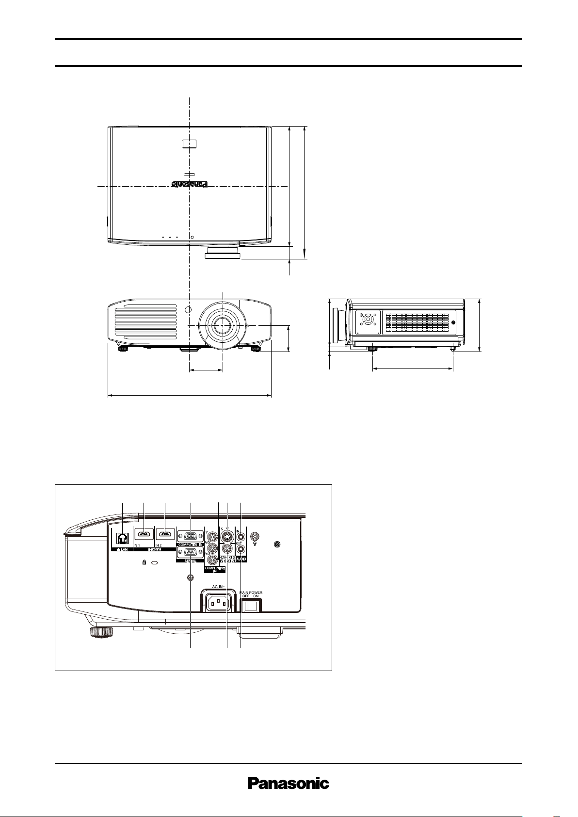
LCD Projector
Dimensi ons
PT-LZ370
uni t : m m (in ch)
NOT E: This il lu str at io n is not dra wn to sc al e.
Terminals
1 LAN c onn ector
2 HDMI 1 i npu t
3 HDMI 2 i npu t
4 Compute r input
5 Compone nt input
6 S-Video in put
7 Audio in put
8 Serial inp ut
9 Video inpu t
10 Au dio outpu t
As of D ecemb er 201 1
SFL11M 020 -2
4 / 1 1
Page 5

S P E C F I L E
Upper edge of projected image
Lower edge of projected image
Projected image
L
L
HH
Projected image
L
230
(9-1/16)
65 (2-9/16)
H
70
(2-3/4)
62
(2-7/16)
∅49
(1-15/16)
∅43
(1-11/16)
Adjustable in
20 mm (25/32) steps
370.5–450.5
(14-19 /3 2–17-3 /4 )
1.02 m
1.27 m
1.52 m
1.78 m
2.03 m
2.29 m
2.54 m
3.05 m
3.81 m
5.08 m
6.35 m
7.62 m
1.1
1.4
1.7
2.0
2.3
2.6
2.9
3.5
4.3
5.8
7.3
8.7
2.3
2.9
3.5
4.1
4.7
5.2
5.8
7.0
8.7
11.6
14.6
17.5
-0.08
-0.09
-0.11
-0.13
-0.15
-0.17
-0.19
-0.22
-0.28
-0.37
-0.47
-0.56
0.58
0.71
0.86
1.00
1.15
1.29
1.44
1.71
2.15
2.86
3.58
4.30
–
–
–
–
–
–
–
–
–
–
–
–
40˝
50˝
60˝
70˝
80˝
90˝
100˝
120˝
150˝
200˝
250˝
300˝
/
/
/
/
/
/
/
/
/
/
/
/
(3.7)
(4.6)
(5.6)
(6.5)
(7.5)
(8.4)
(9.4)
(11.3)
(14.2)
(19.0)
(23.8)
(28.6)
(7.5)
(9.4)
(11.3)
(13.3)
(15.2)
(17.1)
(19.0)
(22.8)
(28.6)
(38.1)
(47.7)
(57.2)
(-0.26
(-0.30
(-0.36
(-0.43
(-0.49
(-0.56
(-0.62
(-0.72
(-0.92
(-1.21
(-1.54
(-1.84
1.90)
2.33)
2.82)
3.28)
3.77)
4.23)
4.72)
5.61)
7.05)
9.38)
11.75)
14.11)
–
–
–
–
–
–
–
–
–
–
–
–
Projection size
[diagonal]
Projection distance [L]
Min [wide] Max [telephoto]
Height from the edge of screen
to center of lens [H]
LCD Projector
Standard s ett ing-up po sit ion
PT-LZ370
uni t : m m (in ch)
NOT E:
Ill us tr ati on s sho w the pro je cto r ins talle d
usi ng opti ona l cei li ng mou nt brac ket
ET-PK A1 10H .
Thi s ill us tra ti on is not drawn to sca le .
C a u t io n :
• All c on struction work should be done by a q ua li fied tech ni ci an .
• When mounting to the ceiling, use the special moun ti ng brac ke t. To prevent the p rojector fro m swaying o r dropping, attach the wire that is inc lu de d with the projector b et we en the mounting bracket and the ceil in g.
Proj ection di stance fo r 16:9 aspect ra tio screen
• The val ue for H (the he ig ht fro m the ed ge of the scre en to the centre of th e len s) is the valu e whe n the hor iz ontal opti cal axis shif t func ti on is
• The val ue for L (dis tan ce to scree n) vari es sli gh tly depe nd ing on the zoo m len s char ac te ris ti cs .
• At the sho rt es t proj ec tio n dis ta nce , the zoom le ns ch aract er istic s may ca us e slig ht imag e dist or ti on.
As of D ecemb er 201 1
SFL11M 020 -2
not used . The va lu e decr ea ses when the hor izo nt al op tical axis shift func ti on is use d. For detail s, see Shift ran ge on page 6.
5 / 1 1
Page 6

S P E C F I L E
0.65V 0.65V
0.26H 0.26H
H
(Width of
projected image)
V
(Height of
projected image)
Standard position
of projected image
-30°
+30°
-10°
+10°
LCD Projector
PT-LZ370
Calcula tio n of th e proj ection di stance
For a screen siz e diff erent from the ch art shown on the page 5, use th e equation below to calcu late
the p rojec tio n distanc e.
16:9 mini mu m L (m) = (diagon al scre en size in inche s) × 0.0 29 2 - 0.054
maxi mu m L (m) = (diagon al scre en size in inche s) × 0.0 58 3 - 0.041
NOT E: The acc ura cy of calc ula te d val ue by the form ula show n abo ve is ±5% .
Shift ra nge
Optical axis shift function allows to sh ift the po sition of a pro jected im age as shown below.
Install abl e angle
Install the proj ector at an angle within th e rang e shown be low.
• Vertical directio n
The p rojec tor may be insta lled a t a vertical
angle of ±30°.
As of D ecemb er 201 1
SFL11M 020 -2
• Horizont al direc tio n
The p rojec tor may be installed a t a horizontal
angle of ±10°.
6 / 1 1
Page 7

S P E C F I L E
Display mode Display
resolution
(dots)
*
1
Scanning frequency
H
(kHz)V(kHz)
Dot clock
frequency
(MHz)
Format Plug and Play
compatibility
HDMI
input
Computer
input
720 × 480i
720 × 576i
720 × 480i
720 × 576i
720 × 483
720 × 576
1,280 × 720
1,280 × 720
1,920 × 1,080i
1,920 × 1,080
640 × 400
640 × 480
800 × 600
832 × 624
1,024 × 768
1,152 × 864
1,152 × 870
1,280 × 720
1,280 × 768
1,280 × 800
1,280 × 960
1,280 × 1,024
1,400 × 1,050
1,440 × 900
1,600 × 1,200
1,680 × 1,050
1,920 × 1,200
15.7
15.6
15.7
15.6
31.5
31.3
45.0
37.5
33.8
28.1
27.0
67.5
56.3
66.6
55.6
37.9
31.5
31.5
31.5
35.0
37.5
37.9
43.3
35.2
37.9
46.9
48.1
53.7
49.7
39.6
48.4
56.5
60.0
68.7
64.0
67.5
77.1
68.7
37.1
44.8
39.6
47.8
41.3
49.7
60.0
64.0
80.0
91.1
64.0
65.2
82.2
55.9
75.0
65.3
74.0
59.9
50.0
59.9
50.0
59.9
50.0
60.0
50.0
60.0
50.0
24.0
60.0
50.0
59.9
49.9
85.1
59.9
59.9
70.1
66.7
75.0
72.8
85.0
56.3
60.3
75.0
72.2
85.1
74.6
50.1
60.0
70.1
75.0
85.0
70.0
74.9
85.0
75.1
49.8
59.9
49.9
59.9
50.0
59.8
60.0
60.0
75.0
85.0
60.0
60.0
75.0
59.9
60.0
60.0
59.9
–
–
13.5
13.5
27.0
27.0
74.3
74.3
74.3
74.3
74.3
148.5
148.5
138.5
141.5
31.5
25.2
25.2
25.2
30.2
31.5
31.5
36.0
36.0
40.0
49.5
50.0
56.3
57.3
51.9
65.0
75.0
78.8
94.5
94.2
108.0
120.0
100.0
60.5
74.5
65.3
79.5
68.0
83.5
108.0
108.0
135.0
157.5
108.0
122.6
155.9
106.5
162.0
146.3
154.0
NTSC/NTSC4.43/PAL-M/PAL60
PAL/PAL-N/SECAM
525i (480i)
625i (576i)
525p (480p)
625p (576p)
750 (720)/60p
750 (720)/50p
1125 (1080)/60i
1125 (1080)/50i
1125 (1080)/24p
1125 (1080)/60p
1125 (1080)/50p
1920 × 1080
*
2
1920 × 1080
VESA400
VGA
SVGA
MAC16
XGA
MXGA
MAC21
1280 × 720
1280 × 768
1280 × 800
MSXGA
SXGA
SXGA+
WXGA+
UXGA
WSXGA+
WUXGA
*
2
VIDEO/S-VIDEO
COMPUTER/YP
BP R
HDMI/COMPUTER/YPBP R
HDMI/COMPUTER
COMPUTER
HDMI/COMPUTER
COMPUTER
HDMI/COMPUTER
COMPUTER
HDMI/COMPUTER
COMPUTER
HDMI/COMPUTER
COMPUTER
HDMI/COMPUTER
COMPUTER
HDMI/COMPUTER
COMPUTER
HDMI/COMPUTER
COMPUTER
No
Yes
No
Yes
No
Yes
No
Yes
No
Yes
No
Yes
No
Yes
No
No
Yes
No
Yes
No
Yes
No
Yes
No
Yes
No
Yes
Yes
No
Yes
No
Yes
No
LCD Projector
List of compa tib le signals
The s ign als that can be input to this proje cto r are shown in the ta ble below. Horizontal scann ing frequencie s of 15 kHz to 91 kHz, ver tic al scanning frequen cies of 24 Hz to 85 Hz , and a dot clock of
162 MHz maxim um can be input .
NOT E: T he nat iv e reso lu ti on of thi s projec to r is 1,92 0 × 1, 08 0 pixe ls. If the dis play res oluti on of the inpu t sig na l is diff ere nt from the
nat iv e reso lu ti on, imag e com pre ss ion or expa ns ion will be used to con ve rt th e inp ut sig na l to a leve l with in the nati ve resol ut io n.
1 Th e “i” app ea ri ng aft er the reso lu ti on ind ic ates an int er laced sign al.
*
2Comp li an t with VESA CVT-RB (Co or din at ed Vi deo Timi ng-Re du ced Blan ki ng) .
*
As of D ecemb er 201 1
SFL11M 020 -2
PT-LZ370
7 / 1 1
Page 8

S P E C F I L E
6
15
9
Start
(1 byte)
End
(1 byte)
Colon
(1 byte)
Semicolon
(1 byte)
ID designator:
01 to 06: Projector ID number
ZZ: All units (ID ALL)
ID 2 characters
(2 bytes)
(2 bytes)
Parameters
(undefined length)
Command
(3 bytes)
(Control and/or query commands)
STX ETXC1P1P2...PnC2A DI1I2 C3: ;
1
2
3
4
5
6
7
8
9
1
2
3
4
5
6
7
8
9
PC (DTE)Projector
NC
NC
NC
NC
NC
NC
NC
NC
LCD Projector
PT-LZ370
Serial con nec tor
The s eri al connector complies wi th RS-232C. To control the project or from a pe rsonal co mputer, com mands mu st be input through commu nication softw are, bas ed on the forma t and s ati sfying th e communicatio n conditions shown below.
Pin a ssi gnments a nd signal na mes
Desc ri ption
NC
Tran smitted data
Rece iv ed data
NC
Ground
No.
6
7
8
9
Sign al name
–
RTS
CTS
–
Desc ri ption
NC
Conn ec ted i ntern ally
Conn ec ted i ntern ally
NC
D-s ub 9-pi n (fem al e) Se ri al inp ut
No.
1
2
3
4
5
Sign al name
–
TXD
RXD
–
GND
Communi cat ion condi tions (factory setting)
Sign al level
Sync hr on ization method
Baud rate
Pari ty
Char ac ter l ength
Stop bit
X param et er
S param et er
RS-2 32 C-com pl iant
Star t- stop syn ch ro nizatio n
9,60 0 bps
None
8 bits
1 bit
None
None
Basic fo rmat
Tran smi ssion from the compu ter begin s with STX, t hen the ID , command , paramet er, and ET X are sent
in th is order. Add p arameters ac cordi ng to the detai ls of control.
CAU TIO N
• I t may not be possi ble to sen d or receiv e comma nds for about 10 to 60 seco nds whe n the lamp is fir st turn ed on. If this occur s, wait fo r 60 sec ond s, then try sendi ng or recei vin g again .
• W hen se ndi ng mult ipl e comma nds , be sure to wait for at least 0.5 secon d after rec eiv ing a r esp ons e from the proj ect or befo re send ing th e next
com man d.
• A ddi tio nal ti me is somet ime s requi red for respon se due to proc ess ing in sid e the proje cto r. Set the time- out pe rio d for comma nd resp ons e to 10
sec ond s or more.
• W hen us ing two or mor e units , set diffe ren t IDs for each uni t.
Cable sp eci fication s
As of D ecemb er 201 1
SFL11M 020 -2
8 / 1 1
Page 9

S P E C F I L E
PON*
1
POF*
1
AVL:<pl>
IIS:<input signal>
OST
OFZ:<off on>
OEN
VPM:NAT
VPM:STD
VPM:CIN
VPM:DYN
VPM:DIC
VPM:BBD
VPM:WBD
VS1:00
VS1:01
VS1:05
VS1:06
VS1:09
AUU
AUD
OMN
OCU
OCD
OCL
OCR
OAS
OSH*
1/*2
TSD:<date>
TST:<time>
Power on (standby mode on)
Power off (standby mode off)
Volume control
Input signal selection
The same function as “default” button
Freeze
Enter
Picture mode: Natural
Picture mode: Standard
Picture mode: Cinema
Picture mode: Dynamic
Picture mode: DICOM
Picture mode: Blackboard
Picture mode: Whiteboard
Aspect mode: Auto
Aspect mode: Normal
Aspect mode: Native
Aspect mode: Full
Aspect mode: H-fit
Volume up
Volume down
Menu
Cursor up
Cursor down
Cursor left
Cursor right
Auto setup
AV mute
Date setting
Time setting
PON
*
1
POF*
1
AVL:<pl>
IIS:<input signal>
OST
OFZ:<off on>
OEN
VPM:NAT
VPM:STD
VPM:CIN
VPM:DYN
VPM:DIC
VPM:BBD
VPM:WBD
VS1:00
VS1:01
VS1:05
VS1:06
VS1:09
AUU
AUD
OMN
OCU
OCD
OCL
OCR
OAS
OSH*
1/*2
TSD:<date>
TST:<time>
–
–
0
–
–
0
–
–
–
–
–
–
–
–
–
–
–
–
–
–
–
–
–
–
–
–
–
–
–
–
–
–
63
–
–
1
–
–
–
–
–
–
–
–
–
–
–
–
–
–
–
–
–
–
–
–
–
–
–
–
Command: <Parameter> Function Callback: <Parameter> Parameter value
Min Max
Command Description Callback
<Parameter>
QPW
Q$S
QIN
QAV
QPM
QFZ
Q$L
QSH
QKS
QGD
QGT
Standby power status
Lamp status
Input signal status
Volume adjustment value
Picture mode status
Freeze status
Lamp run time
AV mute function status
Keystone correction status
Date setting status
Time setting status
Natural
Standard
Cinema
Dynamic
DICOM
Blackboard
Whiteboard
<power condition>
<lamp condition>
<input signal>
<pl>
NAT
STD
CIN
DYN
DIC
BBD
WBD
<off_on>
<acctch>
<off_on>
<pl>
<date>
<time>
LCD Projector
Control co mma nds
PT-LZ370
1 Do no t sen d PON, POF or OSH comm and s con tinuo us ly in a shor t per io d of time . Doi ng so may burs t the lamp or shor ten the lam p
*
rep la cem en t cyc le.
2 Wh en a comm an d tha t cann ot be exec ute d dur in g stan db y mode is sent , the pr oje ct or wi ll se nd an ER40 1 comm an d in repl y.
*
Status request com man ds
As of D ecemb er 201 1
SFL11M 020 -2
9 / 1 1
Page 10

S P E C F I L E
STX AVL : 30 ETX
Start Command Parameter End
Parameter format Size (Byte) Definition
<pl>
<off on>
<input signal>
<power condition>
<lamp condition>
<acctch>
<date>
<time>
3 (1 or 2 bytes also
possible when
under control)
1
3
3
1
4
8
6
Decimal without signs: 0– 999 (000, 001, 002...999)
Decimal with signs: -99 to +99 (-99...-01, +00, +01, +02...+99)
Callback from the projector is 3 Byte.
0 = off, 1 = on
HD1 = HDMI 1, HD2 = HDMI 2, RG1 = computer,
YUV = component, VID = video, SVD = S-Video
000 = power off (standby mode off), 001 = power on (standby mode on)
0 = standby, 1 = lamp on under control, 2 = lamp on,
3 = lamp off under control
Dicimal without signs: 0000-9999 hours
y1y2y3y4m1m2d1d2w = year (y) month (m) day (d) day of week (w)
Day of week: Monday = 1, Tuesday = 2, ... Sunday = 7
h1h2m1m2s1s2 = hour (h) minute (m) second (s)
LCD Projector
Paramet er for mat
NOT E: If a wro ng co mm and is rece ive d, the proj ec to r will send an ER401 or ER40 2 com man d to the comp ute r.
Command examp le
To set t he volume to +30, send the com man d as sh own below.
PT-LZ370
NOT E: When se nd ing comm an ds wit ho ut pa ra met er s, a col on (:) is not nec es sar y.
As of D ecemb er 201 1
SFL11M 020 -2
1 0 / 1 1
Page 11

S P E C F I L E
100 mm (3-15/16˝ )
or more
100 mm (3-15/16˝ )
or more
100 mm (3-15/16˝ )
or more
LCD Projector
PT-LZ370
Notes on projector p lac ement and op eration
The p rojec tor uses a high- wattage lam p that becom es ver y hot d uring operatio n. Please ob ser ve the
followi ng preca utions.
1. Never place objects on top of the project or whi le it is operatin g.
2. Make sure t here is an uno bstructed sp ace of 100 mm (3-15 /16˝ ) o r more around the projecto r’s air
intake ope nings.
3. Do not st ack projector uni ts direc tly on top of one an other for th e purpose of multi ple (stac ked)
projection. Whe n stackin g proj ector units , be sure to provide the am ount of sp ace indic ated belo w
between them. These space re quire ments also app ly to installatio ns whe re only one projector uni t
is opera ting at on e time and the othe r unit is used as a ba ckup.
4. If the projector is ins talled in an enclosed sp ace , ensure that the project or’s intake a nd exhaust
opening s are not blocked. Take particul ar care to ens ure that hot ai r from the ex haust openi ngs is
not s uck ed into the int ake openi ngs .
Dire ction of air in take and exh aus t
Int ak e
Exh au st
Operati ng the projector c ont inuously
1. If the projector is to be operated continuously 12 hours or more, lamp replacement cycle duration
becomes shorter.
2. The lamp replacement cycle duration becomes shorter if the projector is operated repeatedly for short
periods (one hour or less).
Wei ght s and dime nsi on s sho wn are appro xi ma te. Spec ifica ti ons and app ea ran ce are subj ec t to cha nge with ou t noti ce .
Pro du ct ava il ab ili ty diffe rs depe ndi ng on regio n and country. This pr odu ct may be sub jec t to exp ort cont rol regu latio ns .
All othe r tra dem ar ks ar e the pro pe rty of thei r resp ec ti ve tra de mark own er s.
As of D ecemb er 201 1
SFL11M 020 -2
1 1 / 1 1
 Loading...