

Page 1
< 1 >
S PEC F ILE
Product Number : PT-LB75
Product Name : LCD Projector
As of October 2008. Specifications subject to change without notice.
Page 2

S PEC F ILE
PT-LB75
Portable LCD Projector
As of October 2008 < 2 >
Specifications
Power supply
Power consumption
Optical system
LCD panel Panel size
Display method
Drive method
Pixels
Pixel configuration
Lens
Throw ratio
Lamp
Colors
Brightness*
1
Center-to-corner uniformity ratio*
1
Contrast ratio*
1
Resolution RGB
Scanning frequency RGB
YP
BPR
S-Video/Video
Projection size
Optical axis shift
Keystone correction range
On-screen menu
Installation
Built-in speakers Size
Output power
Terminals COMPUTER (RGB) 1 IN
RGB signal
YP
BPR signal
COMPUTER (RGB) 2 IN/1 OUT
RGB signal
YP
BPR signal
VIDEO IN
S-VIDEO IN
COMPUTER AUDIO IN
AUDIO IN
VARIABLE AUDIO OUT
SERIAL
Power cord length
Cabinet material
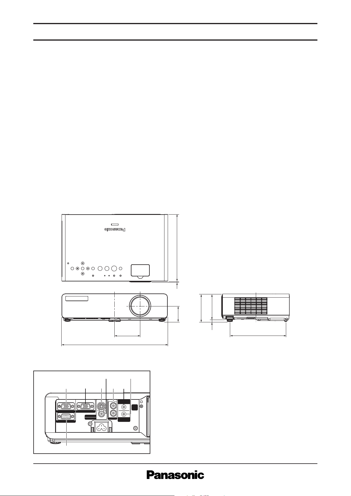
Dimensions (W x H x D)
Weight*
2
Operating environment Temperature
Humidity
100–240 V AC, 50/60 Hz
300 W (approx. 3 W in standby mode with fan stopped. 28 W in
standby mode when controlled by a Web browser.)
Dichroic mirror separation/prism synthesis system
0.63˝ (16 mm) diagonal (4:3 aspect ratio)
Transparent LCD panel (x 3, R/G/B)
Active matrix
786,432 (1,024 x 768) x 3, total of 2,359,296 pixels
Stripe
Manual zoom (1:1–1:1.2), manual focus
F 1.7–1.9, f 18.5– 22.2 mm
1.4–1.7:1
220 W UHM lamp
Full color (16,777,216 colors)
2,600 lumens
85%
500:1 (full on/full off)
1,024 x 768 pixels (Input signals that exceed this resolution will be
converted to 1,024 x 768 pixels.)
Horizontal: 15.00–91.00 kHz, Vertical: 50–85 Hz
480i (525i): f
H 15.75 kHz; fV 60 Hz
576i (625i): f
H 15.63 kHz; fV 50 Hz
480p (525p): f
H 31.50 kHz; fV 60 Hz
576p (625p): f
H 31.25 kHz; fV 50 Hz
720/60p (750p): f
H 45.00 kHz; fV 60 Hz
1080/60i (1125i): f
H 33.75 kHz; fV 60 Hz
1080/50i (1125i): f
H 28.13 kHz; fV 50 Hz
NTSC, NTSC4.43, PAL-M, PAL60: f
H 15.75 kHz; fV 60 Hz
PAL, SECAM, PAL-N: f
H 15.63 kHz; fV 50 Hz
838–7,620 mm (33–300 inches) diagonally, 4:3 aspect ratio
5:1 (fixed)
Vertical: approx. ±30°
17 languages: English, French, German, Spanish, Italian, Korean,
Russian, Chinese, Japanese, Swedish, Norwegian, Danish, Portuguese,
Polish, Hungarian, Czech, and Thai
Front/rear, ceiling/desk (menu selection)
4 x 2 cm, x 1, oval
1.0 W (monaural)
D-sub HD 15-pin x 1
R, G, B: 0.7 Vp-p, 75 Ω, Sync on green: 1.0 V [p-p], 75 Ω,
HD/SYNC, VD: TTL (positive/negative polarity compatible)
Y: 1.0 V [p-p] (including sync signal), 75 Ω, P
B, PR: 0.7 Vp-p, 75 Ω
D-sub HD 15-pin x 1 (input/output selectable using on-screen menu)
R, G, B: 0.7 V [p-p], 75 Ω, Sync on green: 1.0 V [p-p], 75 Ω,
HD/SYNC, VD: TTL (positive/negative polarity compatible)
Y: 1.0 V [p-p] (including sync signal), 75 Ω, P
B, PR: 0.7 V [p-p], 75 Ω
RCA pin x 1, 1.0 Vp-p, 75 Ω
Mini DIN 4-pin x 1, Y: 1.0 V [p-p], C: 0.286 V [p-p], 75 Ω
M3 (L, R) x 1, 0.5 V [rms], for COMPUTER (RGB) 1 and 2
RCA (L, R) x 1, 0.5 V [rms], for VIDEO and S-VIDEO
M3 (L, R) x 1, 0 – 2.0 V [rms]
D-sub 9-pin x 1, for external control (RS-232C)
2 m/6.6´
Moulded plastic (PC+ABS)
368 x 88 x 233 mm (14-1/2˝ x 3-15/32˝ x 9-3/16˝)*
2
Approx. 2.96 kg (6.5 lbs.)
0°–40°C (32°–104°F)
20%–80% (no condensation)
Page 3
S PEC F ILE
PT-LB75
Portable LCD Projector
As of October 2008 < 3 >
Remote control unit Power supply
Operation range*
3
Dimensions (W x H x D)
Weight*
2
Supplied accessories
Optional accessories
3 V DC (AA battery x 2)
Approx. 15 m (49´3˝) when operated from directly in front of the signal
receptor
48 x 163 x 24.5 mm (1-7/8˝ x 6-13/32˝ x 31/32˝)
Approx. 117 g (4.1 oz) (including batteries)
Power cord
Power cord secure lock
Wireless remote control
Batteries for remote control
VGA cable for RGB signals (1.8 m/5´11˝)
Carrying bag
Replacement lamp unit: ET-LAB80
Ceiling mount bracket: ET-PKB80
*1: Measurement, measuring conditions, and method of notation all comply with ISO 21118 international standards.
*2: Average value. May differ depending on models.
*3: Operation range differs depending on environments. Weights and dimensions shown are approximate. Specifications
subject to change without notice.
Terminals
COMPUTER 1 IN
SERIAL
AUDIO IN
COMPUTER 2 IN/1 OUT
S
AC IN~
L
R
VIDEO IN
S-VIDEO IN
COMPUTER
AUDIO IN
VARIABLE
AUDIO OUT
1
8
23
47
56
1 COMPUTER (RGB) 1 input
2 COMPUTER (RGB) 2 input/COMPUTER (RGB) 1 output
3 S-Video input
4 Video input
5 Audio input for Video/S-Video
6 Audio output
7 Audio input for COMPUTER 1/2
8 Serial
Dimensions
unit : mm (inch)
NOTE: This illustration is not drawn to scale.
Weights and dimensions shown are approximate. Specifications are subject to change without notice. This product may be subject to
export control regulations. All other trademarks are the property of their respective trademark owners. Projection images simulated.
233
(9-3/16˝)
3
(1/8˝)
97
889
(3-13/16˝)
(3-15/32˝)(11/32˝)
194
(7-5/8˝)
368
89
(3-1/2˝)
54.5
(2-5/32˝)
(14-1/2˝)
Page 4

-30°
+30°
0°
S PEC F ILE
PT-LB75
Portable LCD Projector
As of October 2008 < 4 >
Standard setting-up positions
Projected image
Lower edge of projected image
Upper edge of projected image
L
L
L
Projected image
HHW
ø49
70 (2-3/4˝)
ø43
(1-15/16˝)
(1-11/16˝)
117
(4-19/32˝)
357–437
(14-1/16˝–
17-7/32˝)
Adjustable
in 20-mm
(15/32-inch) step.
65 (2-9/16˝)
81 (3-3/16˝)
unit : mm (inch)
NOTE:
Illustrations show the projector installed
using optional ceiling bracket.
This illustration is not drawn to scale.
L: Distance to screen
H: Height from the edge of screen to
center of lens
* This distance is especially recommend-
ed for ceiling-mounted use and other
permanent installations.
NOTE:
Values shown are approximate.
The value for L (distance to screen)
varies slightly depending on the zoom
lens characteristics.
When the shortest projection distance is
used, a small amount of distortion may
occur in the image due to the zoom lens
characteristics.
0.84 m
1.02 m
1.27 m
1.52 m
1.78 m
2.03 m
2.29 m
2.54 m
3.05 m
3.81 m
5.08 m
6.35 m
7.62 m
–
1.1 m
1.4 m
1.7 m
2.0 m
2.3 m
2.6 m
2.9 m
3.5 m
4.3 m
5.8 m
7.3 m
8.7 m
1.1 m
1.4 m
1.7 m
2.1 m
2.4 m
2.8 m
3.1 m
3.5 m
4.2 m
5.2 m
7.0 m
8.7 m
10.5 m
0.08 m
0.10 m
0.13 m
0.15 m
0.18 m
0.20 m
0.23 m
0.25 m
0.30 m
0.38 m
0.51 m
0.64 m
0.76 m
33˝
40˝
50˝
60˝
70˝
80˝
90˝
100˝
120˝
150˝
200˝
250˝
300˝
–
3.7´
4.7´
5.6´
6.6´
7.6´
8.5´
9.5´
11.4´
14.3´
19.0´
23.8´
28.6´
3.7´
4.5´
5.6´
6.8´
7.9´
9.1´
10.2´
11.4´
13.7´
17.1´
22.9´
28.7´
34.4´
0.28´
0.33´
0.42´
0.50´
0.58´
0.67´
0.75´
0.83´
1.00´
1.25´
1.67´
2.08´
2.50´
/
/
/
/
/
/
/
/
/
/
/
/
/
/
/
/
/
/
/
/
/
/
/
/
/
/
/
/
/
/
/
/
/
/
/
/
/
/
/
/
/
/
/
/
/
/
/
/
/
/
/
/
Projection size
(diagonal)
Height from the edge of screen
to centre of lens (H)
Projection distance (L)
Min (wide) Max (telephoto)
Calculation of the projection distance
For a screen size different from the above, use the equation below to calculate the projection distance.
Aspect ratio 4 : 3
minimum L (m) = (diagonal screen size in inches) x 0.0292 – 0.036
maximum L (m) = (diagonal screen size in inches) x 0.0351 – 0.044
NOTE: Distances calculated with the above equations will include a slight error.
Installable Angle
Install the projector at an angle within the range shown below.
• Vertical direction
The projector
may be installed
at a vertical
angle of ±30°.
• Vertical direction
The projector may not be angled horizontally.
Page 5

S PEC F ILE
PT-LB75
Portable LCD Projector
As of October 2008 < 5 >
Computer data compatibility
This projector accepts up to 91 kHz horizontal scanning frequency and 162 MHz dot clock.
NOTE: Pixel thinning is applied to signals that exceed a dot clock frequency of 100 MHz. The display resolution of this projector is 1,024 x 768
pixels. Input signals that exceed this resolution will be converted to 1,024 x 768 pixels.
List of compatible signals
1. The “i” appearing after the resolution indicates an interlaced signal.
2. The following symbols are used to indicate picture quality.
AA Maximum picture quality can be obtained.
A Signals are converted by the image processing circuit before picture is projected.
B Signals are compressed by the image processing circuit before picture is projected.
3. When 750 (720)/60p or 750 (720)/50p signals are input to a computer input terminal, images are projected in the WIDE750 (720) format. Be sure
to run the auto setup function.
Display mode Display
NTSC/NTSC4.43/PAL-M/PAL60
PAL/PAL-N/SECAM
525i (480i)
625i (576i)
525p (480p)
625p (576p)
750 (720)/60p
750 (720)/50p
1125 (1080)/60i
1125 (1080)/50i
VESA70
VESA85
VGA60
VGA65
VGA72
VGA75
VGA85
SVGA55
SVGA60
SVGA70
SVGA75
SVGA85
MAC16
XGA50
XGA60
XGA70
XGA75
XGA85
A768
WXG
WXGA800
MXGA70
MXGA75
MXGA85
MAC21
MSXGA60
SXGA60
SXGA75
SXGA85
SXGA60+
WXGA+
UXGA60
WSXGA+
WUXGA
resolution
(dots)
720 x 480i
720 x 576i
720 x 480i
720 x 576i
720 x 483
720 x 576
1280 x 720
1280 x 720
1920 x 1080i
640 x 400
640 x 480
800 x 600
832 x 624
1024 x 768
1280 x 768
1280 x 800
1152 x 864
1152 x 870
1280 x 960
1280 x 1024
1400 x 1050
1440 x 900
1600 x 1200
1680 x 1050
1920 x 1200
Scanning frequency
1
15.7
15.6
15.7
15.6
31.5
31.3
45.0
37.5
33.8
28.1
31.5
37.9
31.5
35.0
37.9
37.5
43.3
35.2
37.9
48.1
46.9
53.7
49.7
39.6
48.4
56.5
60.0
68.7
39.6
47.8
41.3
49.1
49.7
64.0
67.5
76.7
68.7
60.0
64.0
80.0
91.1
64.0
65.1
55.9
75.0
65.3
74.6
H
(kHz)V(kHz)
59.9
50.0
59.9
50.0
59.9
50.0
60.0
50.0
60.0
50.0
70.1
85.1
59.9
66.7
72.8
75.0
85.0
56.3
60.3
72.2
75.0
85.1
74.6
50.1
60.0
70.1
75.0
85.0
49.9
59.9
50.0
60.2
59.8
71.2
74.9
85.0
75.1
60.0
60.0
75.0
85.0
60.0
59.9
59.9
60.0
60.0
59.9
Dot clock
frequency
(MHz)
–
–
13.5
13.5
27.0
27.0
74.3
74.3
74.3
74.3
25.2
31.5
25.2
30.2
31.5
31.5
36.0
36.0
40.0
50.0
49.5
56.3
57.3
51.9
65.0
75.0
78.8
94.5
65.3
79.5
68.0
69.1
83.5
94.2
108.0
121.5
100.0
108.0
108.0
135.0
157.5
108.0
122.4
106.5
162.0
146.3
193.3
Picture
quality
A
A
A
A
A
A
A
A
A
A
A
A
A
A
A
A
A
A
A
A
A
A
A
AA
AA
AA
AA
AA
A
A
A
A
A
A
A
B
A
A
A
B
B
A
B
A
B
B
B
Input terminal
2
VIDEO/S-VIDEO
COMPUTER (RGB/YP
COMPUTER (RGB/YP
COMPUTER (RGB/YPBP R)
COMPUTER (RGB only)
BPR )
BPR )
3
Page 6

S PEC F ILE
PT-LB75
Portable LCD Projector
As of October 2008 < 6 >
Serial connector
The serial connector complies with RS-232C. To control the projector from a personal computer, commands must be input through communication software, based on the format and satisfying the communication conditions shown below.
Pin assignments and signal names
Communication conditions (factory setting)
Basic format
Transmission from the computer begins with STX, then the ID, command, parameter, and ETX are sent
in this order. Add parameters according to the details of control.
CAUTION
It may not be possible to send or receive commands for about 10 to 60 seconds when the lamp is first turned on. If this occurs, wait for 60 seconds, then
try sending or receiving again. When sending multiple commands, be sure to wait for at least 0.5 second after receiving a response from the projector
before sending the next command. Additional time is sometimes required for response due to processing inside the projector. Set the time-out period for
command response to 10 seconds or more.
NOTE:
If a wrong command is received, the projector will send an ER401 command to the computer.
When sending commands without parameters, a colon (:) is not necessary.
Cable specifications
9
6
1
5
D-sub HD 9-pin, female
No.
Signal name
1
–
2
TXD
3
RXD
4
–
5
GND
Description
NC
Send data
Receive data
Connected internally
Ground
No.
Signal name
6
–
7
CTS
8
RTS
9
–
* Effective when connected to a PC having proper functions.
Signal name
NC
Connected internally
Connected internally
NC
Signal level
Synchronization method
Baud rate
Parity
Character length
Stop bit
X parameter
S parameter
RS-232C-compliant
Start-stop synchronization
9,600 bps
None
8 bits
1 bit
None
None
STX ETXC1 C2 C3 : P1 P2 P3 P4
Start
(1 byte)
(3 bytes)
(Control and/or query commands)
Colon
(1 byte)
Parameter
(1-4 bytes)Command
1
2
3
4
5
6
7
8
9
NC
NC
DSR
NC
End
(1 byte)
NC
NC
NC
NC
PC (DTE)Projector
1
2
3
4
5
6
7
8
9
Page 7

S PEC F ILE
PT-LB75
Portable LCD Projector
As of October 2008 < 7 >
Control commands
Status asking commands
Command: <Parameter> Function Callback: <Parameter> Parameter value
1
PON*
1
POF*
AVL:<pl>
IIS:<input signal>
OST
OFZ:<off on>
OEN
OXG:<off on>
VPM:<NAT>
VPM:<STD>
VPM:<DYN>
VPM:<BBD>
VXX:DLVI0=<+00000>
VXX:DLVI0=<+00001>
VXX:DLVI0=<+00002>
AUU
AUD
OMN
OCU
OCD
OCL
OCR
OAS
2
OSH
*1/*
OIX
DZU
DZD
1
Do not send PON, POF, or OSH commands continuously in a short period of time. Doing so may burst the lamp or shorten the lamp replacement cycle.
*
2
When a command other than OSH is sent while the shutter function is operating, the projector will send an ER401 command in reply and release the shutter function.
*
Power on (standby mode on)
Power off (standby mode off)
Volume control
Input signal selection
The same function as “default” button
Freeze
Enter
Wide mode
Picture mode: Natural
Picture mode: Standard
Picture mode: Dynamic
Picture mode: Blackboard
Daylight View: Off
Daylight View: Auto
Daylight View: On
Volume up
Volume down
Menu
Cursor up
Cursor down
Cursor left
Cursor right
Auto setup
AV mute
Index window
Digital zoom: Enlargement
Digital zoom: Reduction
PON
POF
AVL:<pl>
IIS:<input signal>
OST
OFZ:<off_on>
OEN
OXG:<off_on>
VPM:<NAT>
VPM:<STD>
VPM:<DYN>
VPM:<BBD>
VXX:DLVI0=<+00000>
VXX:DLVI0=<+00001>
VXX:DLVI0=<+00002>
AUU
AUD
OMN
OCU
OCD
OCL
OCR
OAS
OSH
OIX
DZU
DZD
Min Max
–
–
0
–
–
0
–
0
–
–
–
–
–
–
–
–
–
–
–
–
–
–
–
–
–
–
–
–
–
63
–
–
1
–
1
–
–
–
–
–
–
–
–
–
–
–
–
–
–
–
–
–
–
–
Command Description Callback
QPW
Q$S
QIN
QAV
QVC
QVÇs
QVB
QVR
QVS
QWR
QWG
QWB
QHP
QÇuP
QCP
QDC
QSP
QLG
QXG
QVX:DLVI0
QPM
QFZ
Q$L
QSH
QKS
QTE
Standby power status
Lamp status
Input signal status
Volume adjustment value
Color adjustment value
Tint adjustent value
Brightness adjustment value
Contrast adjustment value
Sharpness adjustment value
White balance: R adjustment value
White balance: G adjustment value
White balance: B adjustment value
Horizontal position adjustment value
Vertical position adjustment value
Clock phase adjustment value
Dot clock adjustment value
Projection method status
On-screen menu language
Wide mode status
Daylight View status
Picture mode status
Freeze status
Lamp run time
Shutter function status
Keystone correction status
Color temperature adjustment status
Off
Auto
On
Natural
Standard
Dynamic
Blackboard
<Parameter>
<power condition>
<lamp condition>
<input signal>
<pl>
<pl>
<pl>
<pl>
<pl>
<pl>
<pl>
<pl>
<pl>
<pl>
<pl>
<pl>
<pl>
<pl>
<pl>
<off_on>
<+00000>
<+00001>
<+00002>
<NAT>
<STD>
<DYN>
<BBD>
<off_on>
<acctch>
<off_on>
<pl>
<color temp>
Page 8

S PEC F ILE
PT-LB75
Portable LCD Projector
As of October 2008 < 8 >
Parameter format
Parameter format Size (Byte) Definition
<pl>
<off on>
<input signal>
<installation>
<language>
<power condition>
<lamp condition>
<acctch>
<color temp>
<date>
<time>
3 (1 or 2 bytes also
possible when
under control)
1
3
1
3
3
1
4
1
8
6
Decimal without signs: 0 to 999 (000, 001, 002...999)
Decimal with signs: -99 to +99 (-99...-01, +00, +01, +02...+99)
Callback from the projector is 3 Byte.
0 = off, 1 = on
RG1 = computer 1, RG2 = computer 2, NWP = network,
YUV = component, VID = video, SVD = S-Video
0 = front, 1 = rear, 2 = ceiling and front, 3 = ceiling and rear
ENG = English, DEU = German, FRA = French, ESP = Spanish,
ITL = Italian, JPN = Japanese, CHI = Chinese, POR = Portuguese,
SVE = Swedish, NOR = Norwegian, DAN = Danish, POL = Polish,
CES = Czech, MAG = Hungarian, RUS = Russian, THA = Thai, KOR = Korean
000 = power on (standby mode on), 001 = power off (standby mode off)
0 = standby, 1 = lamp on under control, 2 = lamp off,
3 = lamp off under control
Decimal without signs: 0000-9999 hours
0 = economy, 1 = normal, 2 = high
y1y2y3y4m1m2d1d2w = year (y) month (m) day (d) day of week (w)
Day of week: Monday = 1, Tuesday = 2, ... Sunday = 7
h1h2m1m2s1s2 = hour (h) minute (m) second (s)
Command example
To set the volume to +30, send the command as shown below.
NOTE: If a wrong command is received, the projector will send an ER401 command to the computer.
NOTE: When sending commands without parameters, a colon (:) is not necessary.
STX AVL : 30 ETX
Start Command Parameter End
Page 9

S PEC F ILE
PT-LB75
Portable LCD Projector
As of October 2008 < 9 >
Notes on Projector Placement and Operation:
The projector uses a high-wattage lamp that becomes very hot during operation. Please observe the
following precautions.
1. Never place objects on top of the projector while it is operating.
2. Make sure there is an unobstructed space of 150 mm (5-29/32˝) or more around the projector’s
exhaust openings.
3. If the projector is placed in a box or enclosure, ensure the temperature of the air surrounding the
projector is between 0°C/32°F and 35°C/95°F. Also make sure the projector’s intake and exhaust
openings are not blocked. Take particular care to ensure that hot air from the exhaust openings is
not sucked into the intake openings.
Direction of Air Intake and Exhaust
200 mm (7-7/8˝) or more 500 mm (7-5/8˝) or more 500 mm (7-5/8˝) or more
Operating the Projector Continuously
1. If the projector is to be operated continuously 10 hours or more, lamp replacement cycle duration
becomes shorter.
2. The lamp replacement cycle duration becomes shorter if the projector is operated repeatedly for short
periods (one hour or less).
Intake
Exhaust
Weights and dimensions shown are approximate. Specifications are subject to change without notice. This product may be subject to
export control regulations. All other trademarks are the property of their respective trademark owners. Projection images simulated.
 Loading...