

Panasonic PT-EX600U, PT-EX600EL, PT-EW630U, PT-EW630UL, PT-EW630E Service Manual
...
ORDER NO. VED1205428CE
D10
LCD Projector
Model No. PT-EX600U
PT-EX600E
PT-EX600UL
PT-EX600EL
PT-EW630U
PT-EW630E
PT-EW630UL
PT-EW630EL
Lens is optional for the projectors that “L” follows in model number.
*
© Panasonic Corporation 2012.Unauthorized
copying and distribution is a violation of law.

-2-
Contents
Contents ....................................................................... 2
Safety Instructions ...................................................... 3
Safety precautions ...................................................... 4
Specifications .............................................................. 5
Circuit Protections ......................................................7
Fuse(F601) ................................................................. 7
Thermal fuse(SW902) ................................................ 7
Mechanical sensor switches ....................................... 8
Temperature sensors, wind sensors ........................... 9
Power failure and fan lock detection .........................10
Maintenance ............................................................... 11
Maintenance ............................................................. 11
Replacing the unit ..................................................... 13
Replacing the lamp unit ............................................ 15
How to check lamp runtime ...................................... 16
Warning message on the non-standard lamp used .. 16
Quick maintenance ................................................... 17
Removing and attaching the projection lens .............18
Using the lens antitheft screw ...................................19
Cleaning ................................................................... 20
Cleaning the projection lens ..................................... 20
Cleaning the projector cabinet .................................. 20
Security Function Notice .......................................... 21
Resetting procedure ................................................. 21
Standby Mode Notice ................................................ 22
Mechanical Disassembly .......................................... 23
Optical Parts Disassembly .......................................33
LCD panel type check .............................................. 33
Servicing Notice ........................................................39
Note on main board replacement ............................. 39
1.EEPROM data transfer .......................................... 39
2. Adjustment data setting ........................................ 40
Adjustments ............................................................... 41
Adjustments after parts replacement ........................ 41
Optical Adjustments .................................................. 42
1. Optical axis adjustment ........................................ 43
2. Contrast adjustment ............................................. 47
Electrical Adjustments .............................................. 48
Service adjustment menu operation ......................... 48
Circuit adjustments ................................................... 49
Test points and locations .......................................... 53
Service adjustment data .......................................... 54
Troubleshooting ........................................................ 80
Chassis overview ...................................................... 80
No power .................................................................. 81
No power (power supply) .......................................... 82
No power (power supply) .......................................... 83
No power (power supply) .......................................... 84
No power (fan control) .............................................. 85
No power (lamp control) ........................................... 86
Temperature abnormality .......................................... 87
No picture ................................................................. 88
No sound .................................................................. 89
Motor control problems ............................................. 90
Bus control ................................................................ 91
LED drive & RC control ........................................... 92
Indicators and projector condition ............................. 93
If an indicator turns on .............................................. 94
Power failure detection system ................................ 98
Diagnosis of power failure with RS-232C port ........ 103
Serial control interface ............................................ 104
Control Port Functions ...........................................107
IC Block Diagrams ................................................... 110
Exploded Views & Parts List .............................. SPL-1
Exploded Views ................................................... SPL-2
Mechanical Parts List ........................................ SPL-12
Electrical Parts List ........................................... SPL-14
Schematic Diagram & Circuit Boards Diagram . DIA-1
Pin description of diode, transistor and IC ...........DIA-2
Schematic Diagrams ............................................DIA-3
Printed Wiring Board Diagrams ........................DIA-13
-3-
Safety Instructions
The service technician is required to read and follow the “Safety Precautions” and “Important Safety Notice” in this service manual.
WARNING
This service information is designed for experienced repair technicians only and is not designed for use by the general public.
It dose not contain warnings or cautions to advise non-technical individuals of potential dangers in attempting to service a product.
Products powered by electricity should be serviced or repaired only by experienced professional technicians. Any attempt to service or repair the product or products dealt with in this service information by anyone else could result in serious injury or death.
WARNING : Use UV Radiation eye and skin protection during servicing
CAUTION
Precaution
If using of this projector at high altitudes, “Fan Control” to “ON1” for 1,000 to 2,000m or “ON2” for 2,000 to 2,700m.
(Refer to “PROJECTOR SETUP menu” in Operating Instructions.)
Failure to observe this may cause malfunctions. Never use this projector at an altitude of 2,700m or higher.
Using this projector at high altitude, consult your dealer or Authorized Service Center about preparations.
About lead free solder (PbF)
This projector is using the P.C.Board which applies lead free solder.
Use lead free solder in servicing from the standpoint of antipollution for the global environment.
Notes:
•Leadfreesolder:Sn-Ag-Cu(tin,silverandcopper)hasahighermeltingpoint(approx.217°C)thanstandardsolder.Typicallythemeltingpoint
•is30~40°Chigher.Whenservicing,useahightemperaturesolderingironwithtemperaturelimitationfunctionandsetitto370±10°C.
•Beprecautiousaboutleadfreesolder.Sn-Ag-Cu(tin,silverandcopper)willtendtosplashwhenheatedtoohigh(approx.600°Corhigher).
•UseleadfreesolderfortheP.C.Board(specifiedonitas“PbF”)whichusesleadfreesolder.(Whenyouunavoidablyuseleadsolder,uselead
•solderafterremovingleadfreesolder.Orbesuretoheattheleadfreesolderuntilitmeltscompletely,beforeapplyingleadsolder.)
•AftersoldertodoublelayeredP.CBoards,checkthecomponentsideforexceeesolderwhichmayflowontotheoppositeside.
About the identification of the lead free solder P.C.Board.
For the P.C.Board which applies lead free solder, the symbol as shown in the figure below is printed or stamped on the surface
or the back of P.C.Board.
For US
IMPORTANT SAFETY NOTICE
There are special parts used in Panasonic LCD Projectors which are important for safety. These parts are shaded on the schematic diagram. It is essential that these critical parts should be replaced with manufacturer’s specified parts to prevent shock,
fire, or other hazards. Do not modify the original design without permission of PANASONIC SOLUTIONS COMPANY.
WARNING:
This equipment has been tested and found to comply with the limits for a Class B digital device, pursuant to Part 15 of the FCC
Rules. These limits are designed to provide reasonable protection against harmful interference in a residential installation.
This equipment generates, uses and can radiate radio frequency energy and, if not installed and used in accordance with the
instructions, may cause harmful interference to radio communications. However, there is no guarantee that interference will not
occur in a particular installation.
If this equipment dose cause harmful interference to radio or television reception, which can be determined by turning the equipment off and on, The user is encouraged to try to correct the interference by one or more of the following measures.
- Reorient or relocate the receiving antenna.
- Increase the separation between the equipment and receiver.
- Connect the equipment into an outlet on a circuit different from that to which the receiver is connected.
- Consult the dealer or an experienced radio/TV technician for help.
CAUTION : Any unauthorized changes or modifications to this equipment will void the user’s authority to operate this device.
-4-
Safety Instructions
<PT-FW430U/PT-FW430E/PT-FW430EA/PT-FX400U/PT-FX400E/PT-FX400EA>
1. Safety Precautions
1.1. General Guidelines
1.2. Leakage Current Check
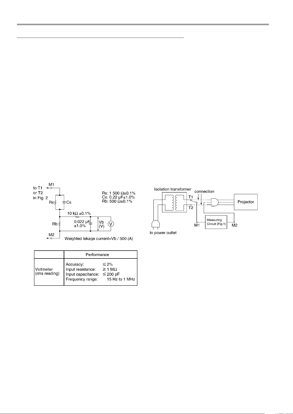
1. Prepare the measuring circuit as shown in Fig.1.
Be sure to use a voltmeter having the performance described in Table 1.
2. Assemble the circuit as shown in Fig. 2. Plug the power cord in a power outlet.
3. Connect M1 to T1 according to Fig. 2 and measure the voltage.
4. Change the connection of M1 from T1 to T2 and measure the voltage again.
5. The voltmeter must read 0.375 V or lower in both of steps 3 and 4. This means that the current must be 0.75mA or less.
6. If the reading is out of the above standard, the projector must be repaired and rechecked before returning to the customer
because of a possibility of an electric shock.
- For continued safety, no modification of any circuit must be attempted.
- Unplug the power cord from the power outlet before disassembling this projector.
- Use correctly the supplied power cord and must ground it.
- It is advisable to use an isolation transformer in the AC power line before the service.
- Be careful not to touch the rotation part (cooling fan, etc.) of this projector when you service with the upper
case removed and the power supply turned ON.
- Observe the original lead dress during the service. If a short circuit is found, replace all the parts overheated
or damaged by the short circuit.
- After the service, all the protective devices such as insulation barriers, insulation papers, shields, and isolation
R-C combinations must be properly installed.
- After the service, check the leakage current to prevent the customer from getting an electric shock.
1.3. UV Precaution and UHM Lamp Precautions
- Be sure to unplug the power cord from the power outlet when replacing the lamp.
- Because the lamp reaches a very high temperature during its operation, wait until it cools completely when replacing
the Lamp Unit.
- The lamp emits small amounts of UV-radiation, avoid direct-eye contact with the light.
- The lamp unit has high internal pressure. If improperly handled, explosion might result.
- Because the high pressure lamp involves a risk of failure, never touch the lamp wire lead during the service.
Fig. 1
Fig. 2
Table. 2
Safety precautions
-5-
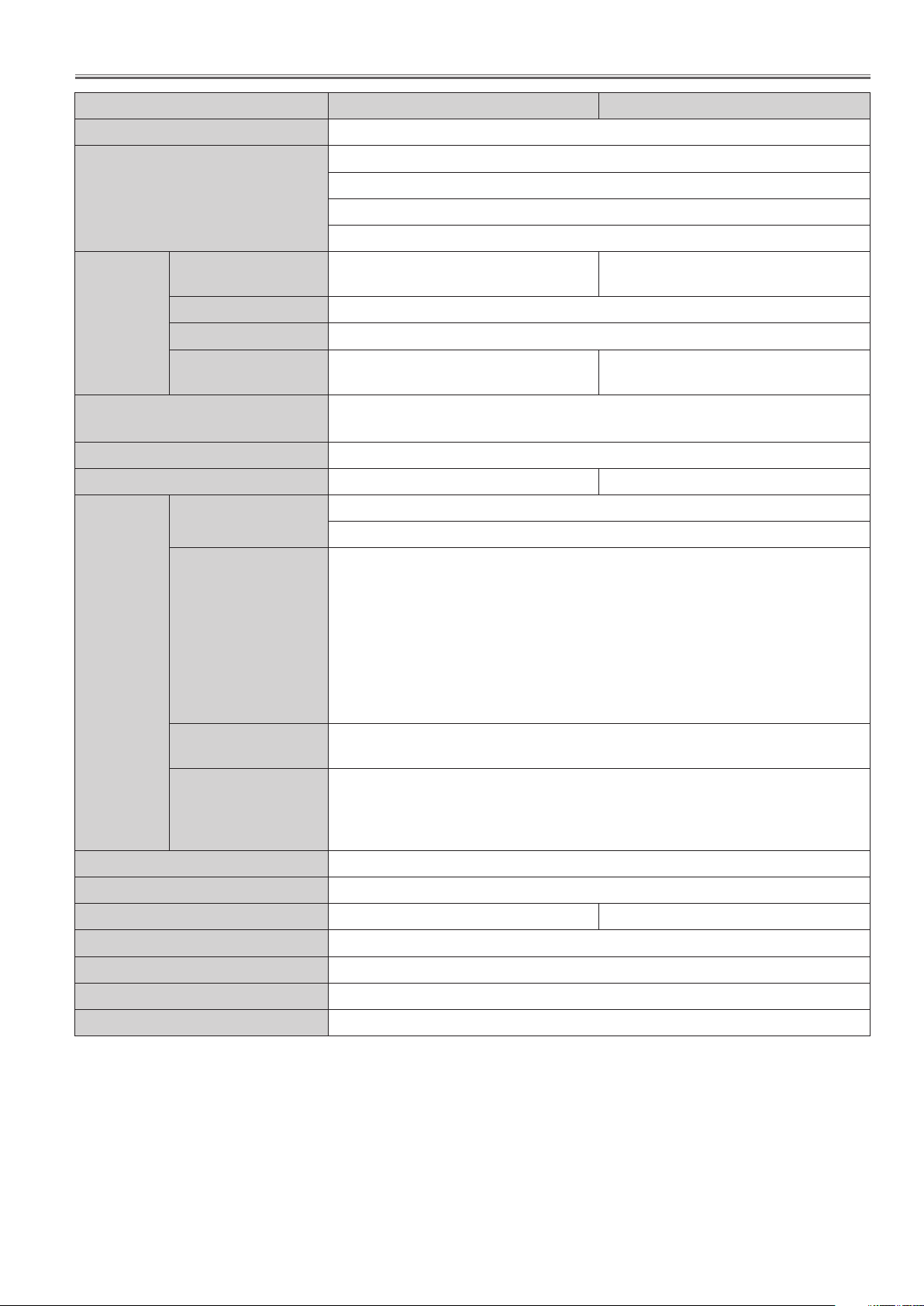
Specifications
Model No. PT-EX600U / E / UL / EL PT-EW630U / E / UL / EL
Power supply
Power consumption
Panel size
LCD panel
Lens*1
Luminous lamp
Light output *2
Applicable
scanning
frequency
*3
Display method
Drive method
Pixels
for RGB signal
for YPBPR signal
AC100 V - 240 V 50 Hz/60 Hz
100 V - 240 V 4.9 A-2.0 A 490 W
When [Standby mode] of [Setting] is set to [ECO]: 0.4 W
When [Standby mode] of [Setting] is set to [Network]: 11 W
When [Standby mode] of [Setting] is set to [Normal]: 15 W
1.93 cm(0.8")
(aspect ratio 4 : 3)
3 transparent LCD panels (RGB)
Active matrix method
786 432
(1 024 x 768) x 3 panels
Motorised zoom (1.6x) / Motorised focus
F 1.7 to 2.3, f 26.9 mm to 45.4 mm
330 W UHM lamp
6 000 lm 5 500 lm
Horizontal 15 kHz to 120 kHz, Vertical 48 Hz to 100 Hz
Dot clock frequency: up to 140 MHz
[525i(480i)] Horizontal 15.75 kHz, Vertical 60 Hz
[525p(480p)] Horizontal 31.5 kHz, Vertical 60 Hz
[750(720)/60p] Horizontal 45 kHz, Vertical 60 Hz
[1 125(1 080)/60i]Horizontal 33.75 kHz, Vertical 60 Hz
[625i(576i)] Horizontal 15.63 kHz, Vertical 50 Hz
[625p(576p)] Horizontal 31.25 kHz, Vertical 50 Hz
[750(720)/50p] Horizontal 37.5 kHz, Vertical 50 Hz
[1 125(1 080)50i] Horizontal 28.13 kHz, Vertical 50 Hz
•HD/SYNCandVterminalsarenotcompliantwith3valuecompositeSYNC
1.91 cm(0.75")
(aspect ratio 16 : 10)
1 024 000
(1 280 x 800) x 3 panels
for Video signal (including S-Video)
for HDMI signal
Color system
Projection size
Screen aspect ratio
Projection scheme
Speaker
Maximum usable volume output
Contrast ratio *1
*1: It is only for the model which with lens.
*2: Measurement, measuring conditions and method of notation all comply with ISO21118 international standards.
*3: For details of video signals that can be projected using this projector, refer to “List of compatible signals”.
Horizontal 15.75 kHz / 15.63 kHz, Vertical 50 Hz / 60 Hz
525p(480p), 625p(576p), 750(720)/60p, 750(720)/50p, 1 125(1080)/60p,
1 125(1 080)/50p, 1 125(1 080)/60i, 1 125(1 080)/50i
•Displayable resolution: VGA to WUXGA (non-interlace)
•Dot clock frequency: up to 162 MHz
7 (NTSC, NTSC4.43, PAL, PAL-N, PAL-M, SECAM, PAL60)
1.01 m-10.1 m(40"-400")
4 : 3 16 : 10
Front / Rear / Mount on Ceiling / Floor (Menu setting system)
1(3.7 cm round-type)
10W
5 000 : 1 (all white / all black)
-6-
Specifications
Model No. PT-EX600U / E / UL / EL PT-EW630U / E / UL / EL
INPUT 1
<DVI_D>
<HDMI>
<RGB>
INPUT 2
<VIDEO>
<YPBPR>
<RGB,SYNC/HD,VD>
Terminals
INPUT 3
<VIDEO>
<YPBPR/YCBCR>
<S-VIDEO>
* Choose one item in the menu
DVI-D 24-pin (Single link), DVI 1.0 compatible, HDCP compatible)
HDMI 19-pin (HDCP and Deep color compatible)
D-sub HD 15-pin (female)
[RGBsignal] 0.7V[p-p]75Ω(WhenG-SYNCisset1.0[p-p]75Ω
HD/
SYNC TTL high impedance, automatic positive/negative polarity
compatible
VD TTL high impedance, automatic positive/
negative polarity compatible
* Choose one item in the menu
BNCx1[VIDEOsignal](1.0V[p-p]75Ω)
BNCx3[YPBPR signal] Y:1.0 V [p-p] including synchronization
signal,PBPR:0.7V[p-p]75Ω
BNCx5[RGBsignal]0.7V[p-p]75Ω(WhenG-SYNCisset1.0[p-p]75Ω
HD/SYNC TTL high impedance, automatic positive/negative polarity compatible
VD TTL high impedance, auto-
matic positive/ negative polarity compatible
* Choose one item in the menu
RCA x 1 [VIDEO signal] (1.0 V [p-p] 75 Ω)
RCA x 3 [YPBPR signal] Y:1.0 V [p-p] including synchronization
signal ,PBPR:0.7V[p-p]75ΩMiniDIN4pin
[S-VIDEOsignal]Y1.0V[p-p],C0.286V[p-p]75Ω,S1
signal compatible
<MONITOR OUT>
<AUDIO IN>
<VARIABLE AUDIO
OUT>
<SERIAL IN>
<LAN>
Power cable length
Cabinet
Dimensions
Weight
Operating environment
Power supply
Remote
control
Operating range
Weight
1 (D-sub HD 15 pin (female)
[RGBsignal] 0.7V[p-p]75Ω(WhenG-SYNCisset1.0[p-p]75Ω
2(M3stereominijack,0.5V[rms],inputimpedance22KΩandmore)
1(RCApinjackx2(L-R),0.5V[rms],inputimpedance22KΩandmore)
1 (M3 stereo mini jack, stereo monitor output compatible,
0V[rms]to2.0V[rms]valuable,outputimpedance2.2kΩandless)
1 (D-sub 9 pin, RS-232C compliant, for computer control use
1 (for RJ-45 network connection, PJLink compatible)
3.0 m(118.1")
Molded plastic
Width: 489.5 mm (19.27")
Height: 164 mm (6.46") (when front adjustable foot shortened)
Depth: 370.1 mm (14.57")*4 (including protractions)
433.8 mm (17.08")*5 (including protractions)
Approx. 9.6 kg(21.12 lbs.) *
Approx. 10.3 kg(22.71 lbs.) *
Operatingenvironmenttemperature:0°C(32°F)to40°C(104°F)*
6
7
8
Operating environment humidity: 20 % to 80 % (no condensation)
DC 3 V (battery (AAA/R03 or AAA/LR03 Type ) x 2)
Approx. 5 m (196.9") (when operated directly in front of receptor)
102 g (3.6 ozs.) (including batteries)
Dimensions
*4: The depth is for the projector that without the projection lens.
*5: The depth is for the projector that with the standard projection lens.
*6: This is an average value. It may differ depending on individual product. It is only for PT-EX600UL, PT-EX600EL,
PT_EW630UL and PT-EW630EL.
*7: This is an average value. It may differ depending on individual product. It is only for PT-EX600U,PT-EX600E, PT-EW630U
and PT-EW630E.
*8:Whenusingtheprojectorathighelevation1000mto2700msealevel,theoperatingenvironmenttemperaturewillbe0°C
to30°C.
•Thepartnumbersofaccessoriesandseparatelysoldcomponentsaresubjecttochangewithoutnotice.
Width : 48 mm (1.89"), Length : 145 mm (5.71"), Height : 27 mm (1.06")
-7-
Circuit Protections
This projector provides the following circuit protections to operate in safety. If the abnormality occurs inside the projector, it will automatically turn off by operating one of the following protection circuits.
Fuse(F601)
A fuse is located inside of the projector. When the ON(G)/
STANDBY(R) indicator is not lighting, the fuse may be
opened. Check the fuse as following steps.
The fuse should be used with the type listed right;
How to replace the fuse
1. The fuse is placed on the power board under the main
board. Remove the cabinet top, main&AV board and
exhaust fan assy.
2. Take the fuse off, and replace the old one with the
specified type.
Fuse Part No: 423 035 4704
TYPE T10AH 250V FUSE
LITTEL FUSE INC. TYPE 0215010.MXEP
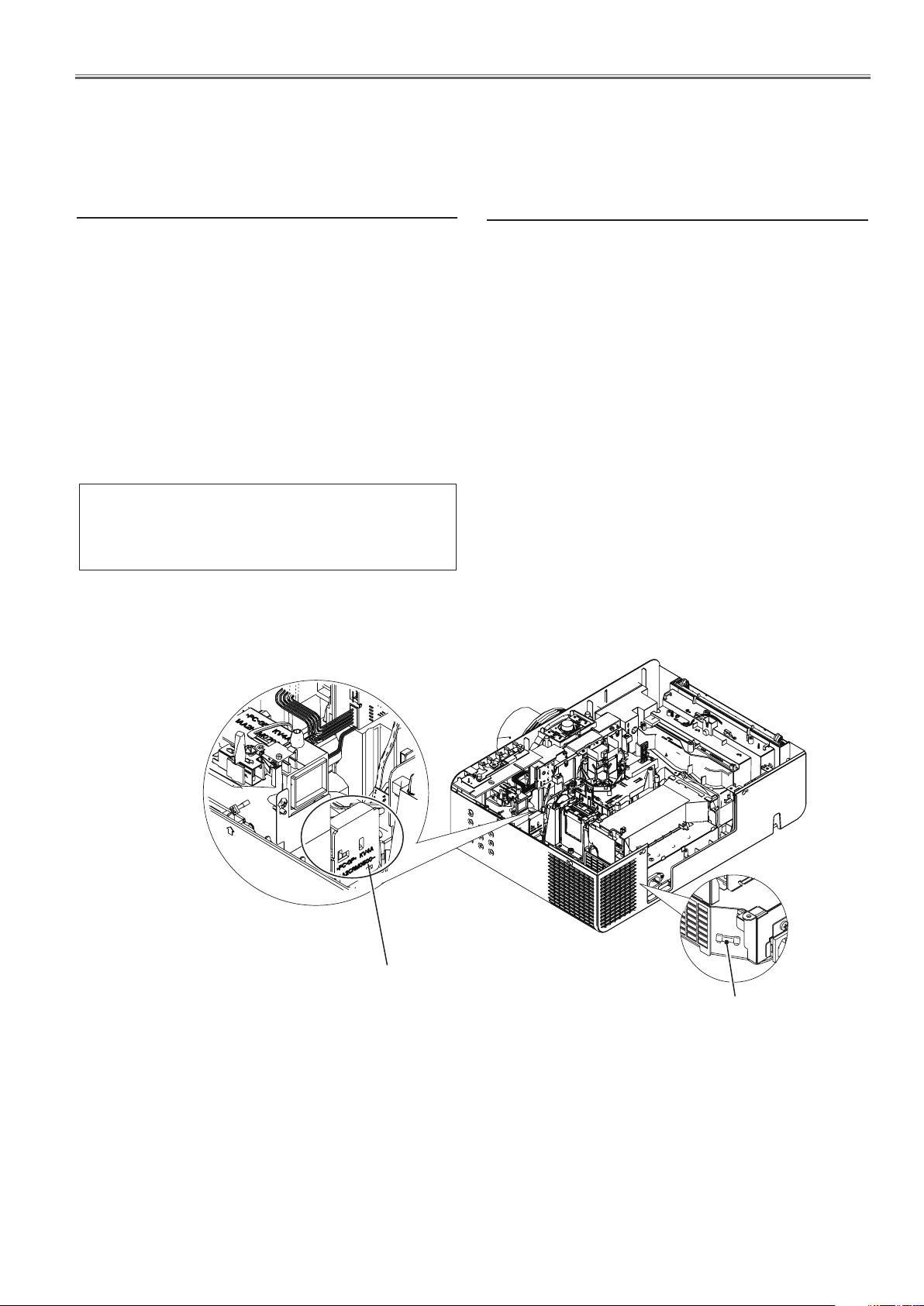
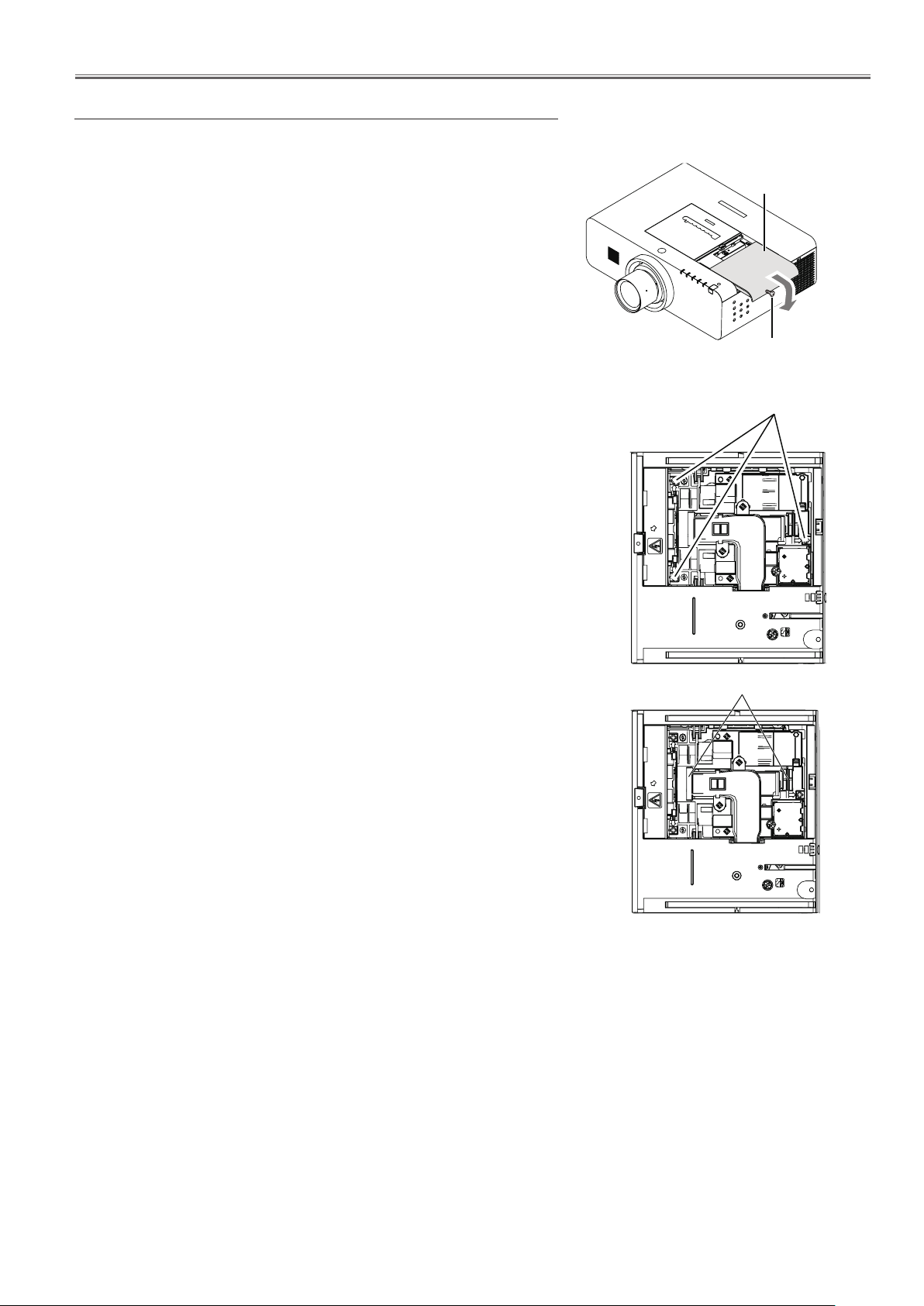
Thermal fuse(SW902)
There is the thermal fuse (SW902) inside of the projector to detect the internal temperature rising abnormally.
Whentheinternaltemperaturereachesnear113˚C,the
thermal fuse opens to cut off the power to the power
circuit.
If the thermal fuse opens, the projector cannot turn on.
Thermal fuse replacement is required.
Thermal fuse
(SW902)
Fuse
(F601)
-8-
Circuit Protections
Mechanical sensor switches
This projector provides 2 mechanical sensor switches, the one is for air filter unit switch (SW1891) and the other one
is for lamp cover switch(SW901).
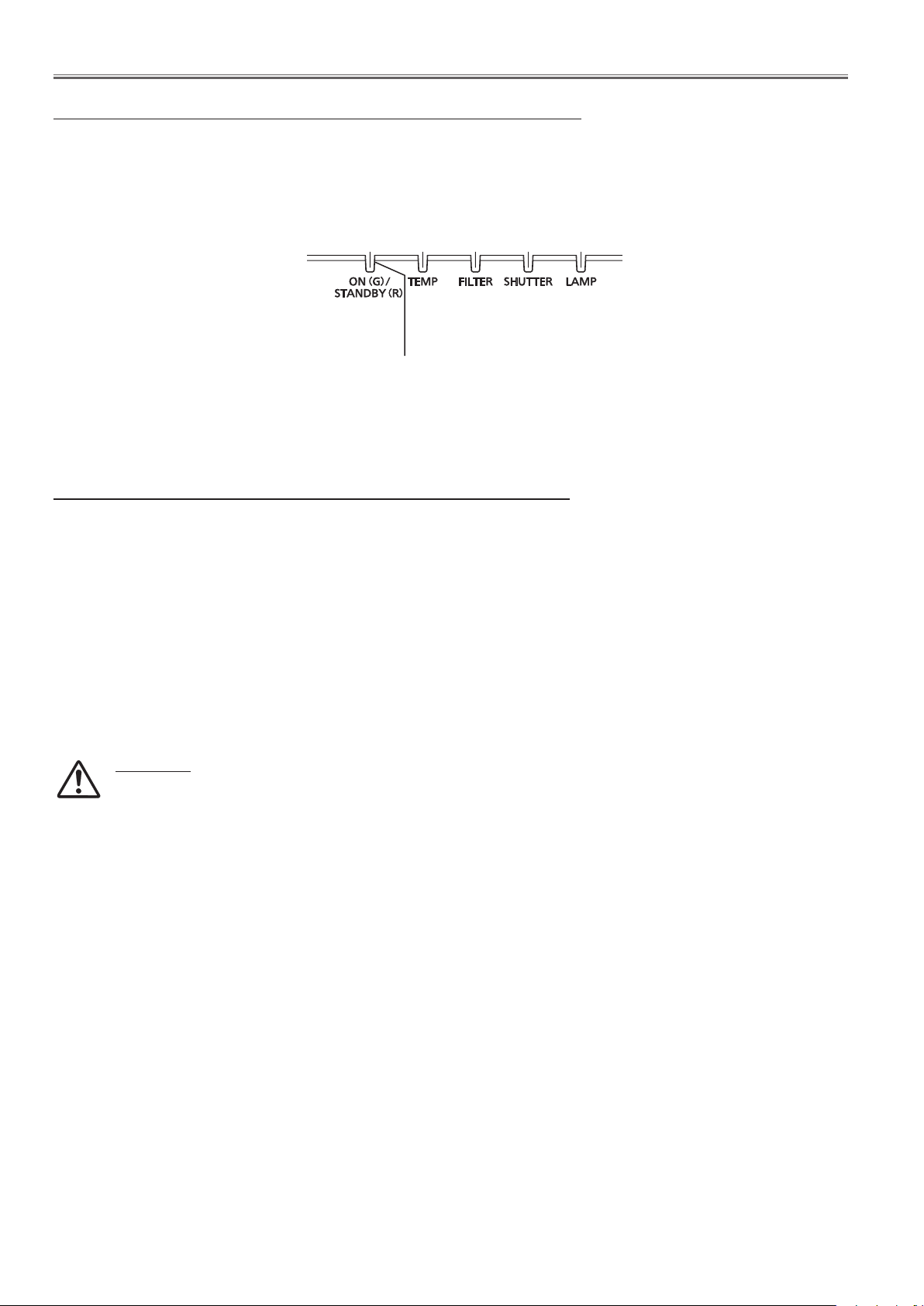
The projector is shut down and the < ON(G)/STANDBY(R)> indicator lights in red and other
indicators are blinking.
The air filter unit switch (SW1891) detects whether the air filter unit is installed correctly. If the air filter unit switch is
not installed correctly, the projector cannot turn on. In this case, the <ON(G)/STANDBY(R)> indicator lights in red and
other indicators are blinking.
- Check that the lamp cover is installed securely.
The projector is shut down and the < ON(G)/STANDBY(R)> and <LAMP> indicators are
blinking.
The lamp cover switch (SW901) detects whether the lamp cover is closed securely. If lamp cover is opened or not
closed completely, the drive signal to the lamp circuit is cut off. After opening the lamp cover for replacing the new
lamp assy, place the lamp cover correctly otherwise the projector cannot turn on.
- Check that the air filter unit is installed securely.
LED indicators
ON(G)/STANDBY(R)
indicator
LAMP indicator
Lamp cover switch(SW901)
Air filter unit
Air filter unit switch
(SW1891)
-9-
Circuit Protections
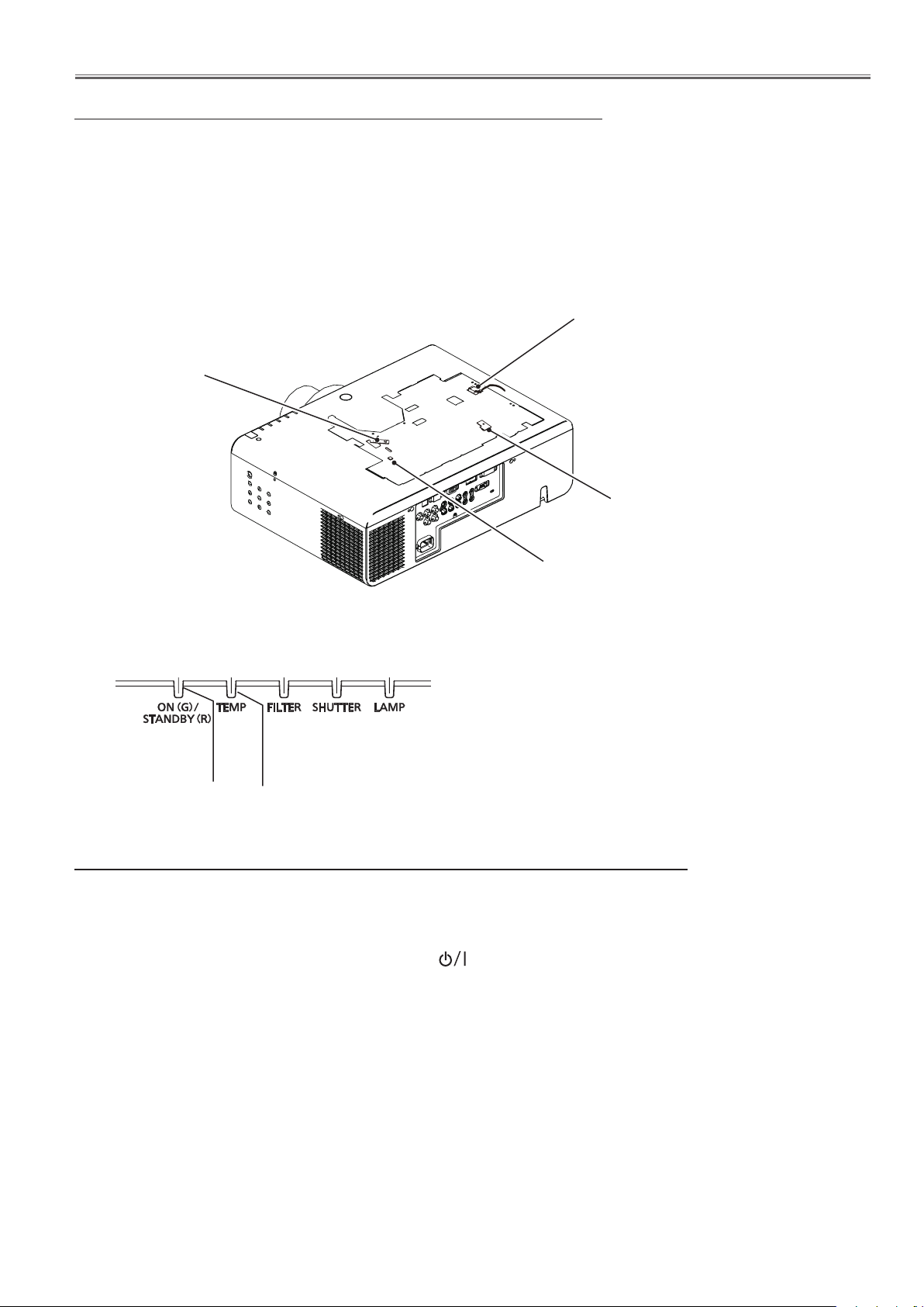
Temperature sensors, wind sensors
The projector provides 3 temperature sensor ICs and 1 wind sensor on the intake duct. These devices are monitoring
the surrounding temperature of the lamp, panel and intake duct, and the wind sensor is monitoring airflow passed
through the air filter in the intake duct.
- Internal temperature sensor A (IC1692) (around the Intake duct)
- Internal temperature sensor B (IC1816) (around the lamp house)
- Internal temperature sensor C (IC1814) (around the panel/prism)
- Wind sensor D (S901) (intake duct)
S901
Wind sensor
IC1814 on the
Sensor C board
IC1692 on the
Sensor A board
IC1816 on the main
board (behind)
Top view of the LED indicators
LED indicators
ON(G)/STANDBY(R)
TEMP. indicator
indicator
The projector is shut down and the < TEMP> indicator is blinking red.
When the temperature inside the projector reaches a certain level, the <TEMP> indicator starts blinking slowly. If the
temperature rises moreover, the projector will be automatically shut down to protect the inside of the projector, and
the <TEMP.> indicator is blinking fast and the <ON(G)/STANDBY(R)> indicator lights in orange. When the projector
has cooled down enough (to its normal operating temperature), the <ON(G)/STANDBY(R)> indicator lights in red and
the projector can be turned on again by pressing the button.
✔Note:
•The<TEMP>indicatorcontinuestoblinkevenafterthetemperatureinsidetheprojectorreturnstonormal.When
the projector is turned on again, the <TEMP> indicator stops blinking.
Check the items below
- Remove dust around the air filter.
- Ventilation slots of the projector are blocked. In such an event, reposition the projector so that ventilation slots are
not obstructed.
- Check if projector is used at higher temperature place (Normal; operating temperature is 0 to 40 ºC or 32 to 104
ºF).
-10-
Circuit Protections
Power failure and fan lock detection
The projector provides the detection circuits of the power failure and the fan lock. When the detection circuit detects
an error at the power supply line or at the fan operation circuit, the projector will turn into the standby mode to protect
the other circuits defective.
Top view of the LED indicators
LED indicators
ON(G)/STANDBY(R)
indicator
The projector is shut down and all indicators are blinking.
When the projector detects an abnormal condition (Power supply lines failure , fans failure), it will be automatically
shut down to protect the inside of the projector and all of indicators blink. In this case, unplug the AC power cord and
plug it, and then turn on the projector once again to verify operation. If the projector cannot be turned on and these
indicators are still blinking, the projector may has an internal error. Unplug the AC power cord. See the troubleshooting chapter.
WARNING
DO NOT LEAVE THE PROJECTOR WITH THE AC POWER CORD CONNECTED UNDER AN
ABNORMAL CONDITION. IT MAY RESULT IN FIRE OR ELECTRIC SHOCK.
-11-
Maintenance
Before replacing the unit
When you perform maintenance or replacement of the parts, make sure to turn off the power and disconnect the
power plug from the wall outlet.
Maintenance
n Outer case
Wipe off dirt and dust using a soft dry cloth.
ò If the dirt is persistent, soak the cloth with water and wring it thoroughly before wiping. Dry off the projector with
a dry cloth.
ò Do not use benzene, thinner, or rubbing alcohol, other solvents, household cleaners. Using them may cause
deterioration of the outer case.
ò When using chemical treated dusters, follow its instruction.
n Front glass surface of the lens
Wipe off the dirt and dust off the front surface of the lens with soft clean cloth.
ò Do not use a cloth that has an abrasive surface or a cloth that is moist, oily, or covered with dust.
ò Do not use excessive force when wiping the lens as it is fragile.
Attention
The lens is made of glass. Impacts or excessive force when wiping may scratch its surface.
Please handle with care.
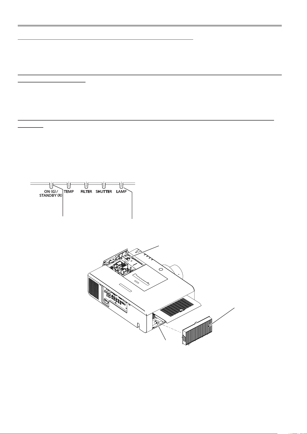
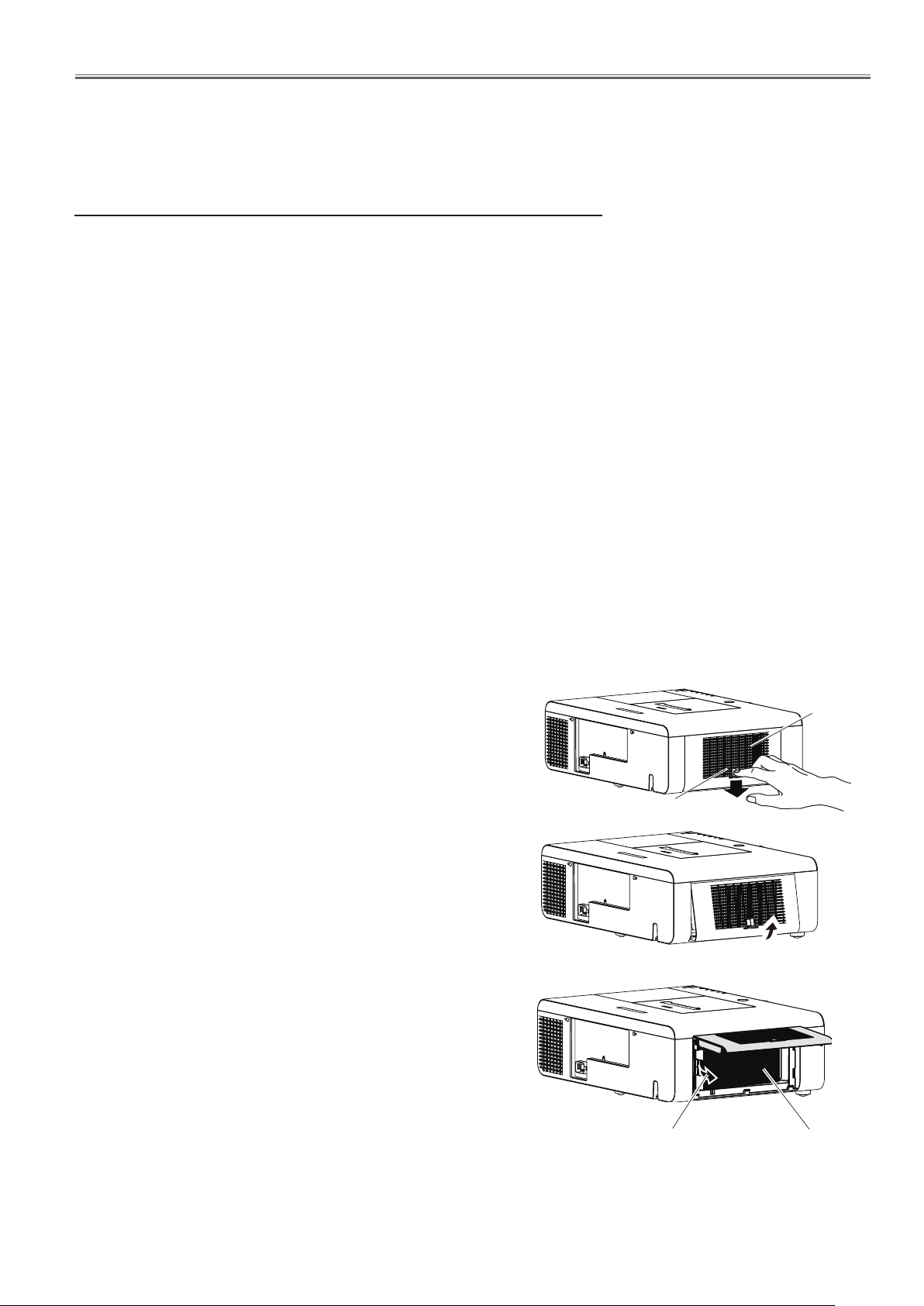
n Air filter unit
Clean the air filter unit in the following cases.
ò
When the replacement message is displayed and the filter
indicator <FILTER> lights up due to a blockage.
ò
The temperature inside the projector becomes high and
the temperature indicator <TEMP> lights, causing the
projector turn off, due to a blockage. (When the power
if turned off, temperature indicator <TEMP> flashes and
standby indicator <ON(G)/STABDBY(R)> lights in red.)
1) Turn off the projector, and unplug the AC power cord
from the AC outlet.
2) Clean up the dust on the projector and around the air
vents.
3) Press t downwards on the filter cover to release the
latch and open the filter cover.
4) Pull out the air filter unit.
ò Pick the tab and frame of the air filter unit, release the
lock with pressing the tab rightwards in the figure,
and then pull.
Filter cover
Latch
Ta b
Air filter unit
-12-
Maintenance
5) Clean the air filter unit.
ò Removing the dust from the air filter unit
(i) Remove the dust from the air filter unit using a vacuum or other cleaner.
•Ifthedustpersistsaftercleaningwithavacuum,washtheairfilterunitinwater.
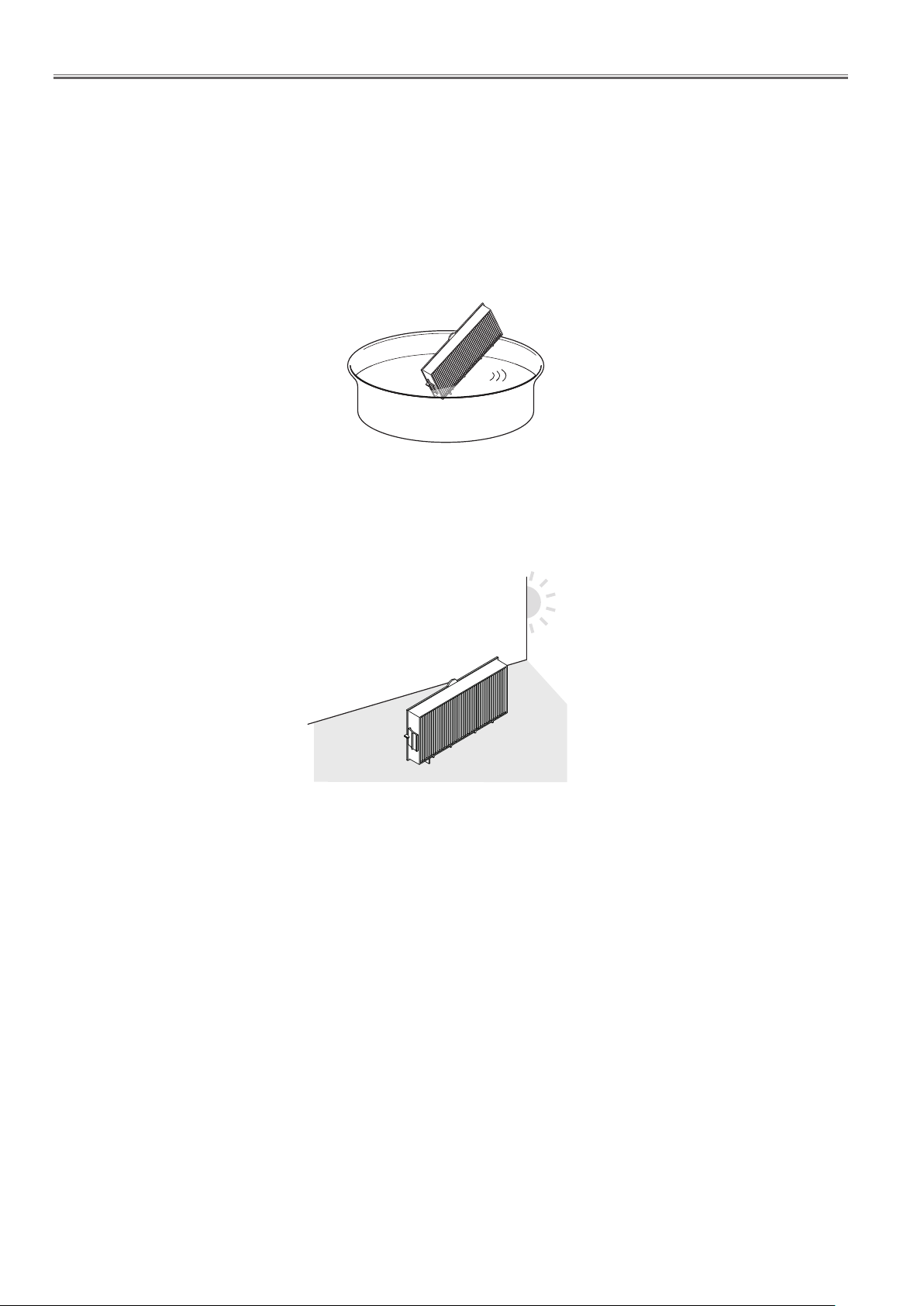
ò Washing the air filter unit
(i) Soak the air filter unit in water or warm water and rinse it lightly.
•Donotusematerialssuchasblushesordetergent.
•Whenyourinsetheairfilterunit,holdtheframeandavoidexcessiveforceonthefilterpart.
(ii) Change the water two or three times while you rinse the air filter unit.
•Rinseituntilthecloudofthewaterclears.Iftheairfilterunitisnotrinsedsufficiently,odormayresult.
ò Drying the air filter unit
Naturally dry the air filter unit in a well-ventilated place, avoiding dust and direct sunlight.
•Donotuseahairdrierorotherdrier.
6) Attach the air filter unit.
ò Hold the air filter unit that the tab is in left side in the figure. put the right side in the figure first, and press the
tab side until make a click sound.
7) Close and press up to lock the filter cover.
ò Make sure that the air filter cover is closed tightly.
8) Reset the filter counter.
ò Turn on the power and perform [Filter counter reset] in the [Setting] menu.
Attention
ò After washing the air filter unit, dry it thoroughly before attaching to the projector. Attaching wet air filter may
cause electric shock or malfunction.
Note
ò Be sure to attach the air filter unit properly. If you use the projector without attaching the air filter unit, the projec-
tor may be damaged due to the dirt or dust.
ò If the air filter unit has been damaged or dirt remains even after washing it, replace it with a a new filter.
ò It is recommended that the air filter unit is replaced after two times of cleaning and reusing.
ò After washing, the capability of the air filter unit may decrease.
ò After washing the air filter unit, reset the filter counter. Otherwise, the power of the projector may be turned off
for safety.

-13-
Maintenance
Replacing the unit
n Air filter unit
The replacement filter is optional. To purchase the product, consult your dealer.
Replacement air filter unit : ET-RFE200
Reset the filter counter.
•Turnonthepowerandperform[Filtercounterreset]inthe[Setting]menu.
Attention
•Turnoffthepowerbeforeyoureplacetheairfilterunit.
•Whenattachingtheairfilterunit,makesurethattheprojectorisstable,andworkinanenvironmentthatissafe,even
in the event of the air filter unit dropping.
•Donotoperatetheprojectorwiththeairfilterunitremoved.Dustmayaccumulateontheopticalelementsdegrading
picture quality.
•Afterreplacingtheairfilterunit,resetthefiltercounter.Otherwise,thepoweroftheprojectormaybeturnedofffor
safety.
-14-
Maintenance
n Lamp unit
The lamp unit is a consumable component. You can check the total usage time using lamp runtime in the information
menu.
It is recommended to ask an authorized engineer to replace the lamp unit. Contact your dealer.
Consult your dealer to purchase a replacement lamp unit.
CAUTION:
n Do not replace the lamp unit when it is hot. (Wait at least 1 hour after use.)
The inside of the cover can become very hot, take care to avoid burn injuries.
Replacement lamp unit : ET-LAE200
n Notes on the replacement of the lamp unit
•Theluminoussourceofthelampismadeofglassandmayburstifyou
hit it against a hard surface or drop it. Please handle with care.
•Aphillipsscrewdriverisrequiredforreplacementofthelampunit.
•Whenreplacingthelampunit,besuretoholditbythehandle.
•Whenreplacingthelampbecauseithasstoppedilluminating.Thereisa
possibility that the lamp may be broken. If replacing the lamp of a projector which has been installed on the ceiling. you should always assume
that the lamp is broken. And you should stand to the side of the lamp
cover, not underneath it. Remove the lamp cover gently .Small pieces of
glass may fall out when the lamp cover is opened. If pieces of glass get
into your eyes or mouth. Seek medical advice immediately.
•Thelampcontainsmercury.Consultyourlocalmunicipalityoryourdeal-
er about correct disposal of used lamp units.
Attention
•Donotuseotherthandesignatedlampunits.
•Thepart numbersofaccessoriesandseparatelysoldcomponentsaresubject
to change without notice
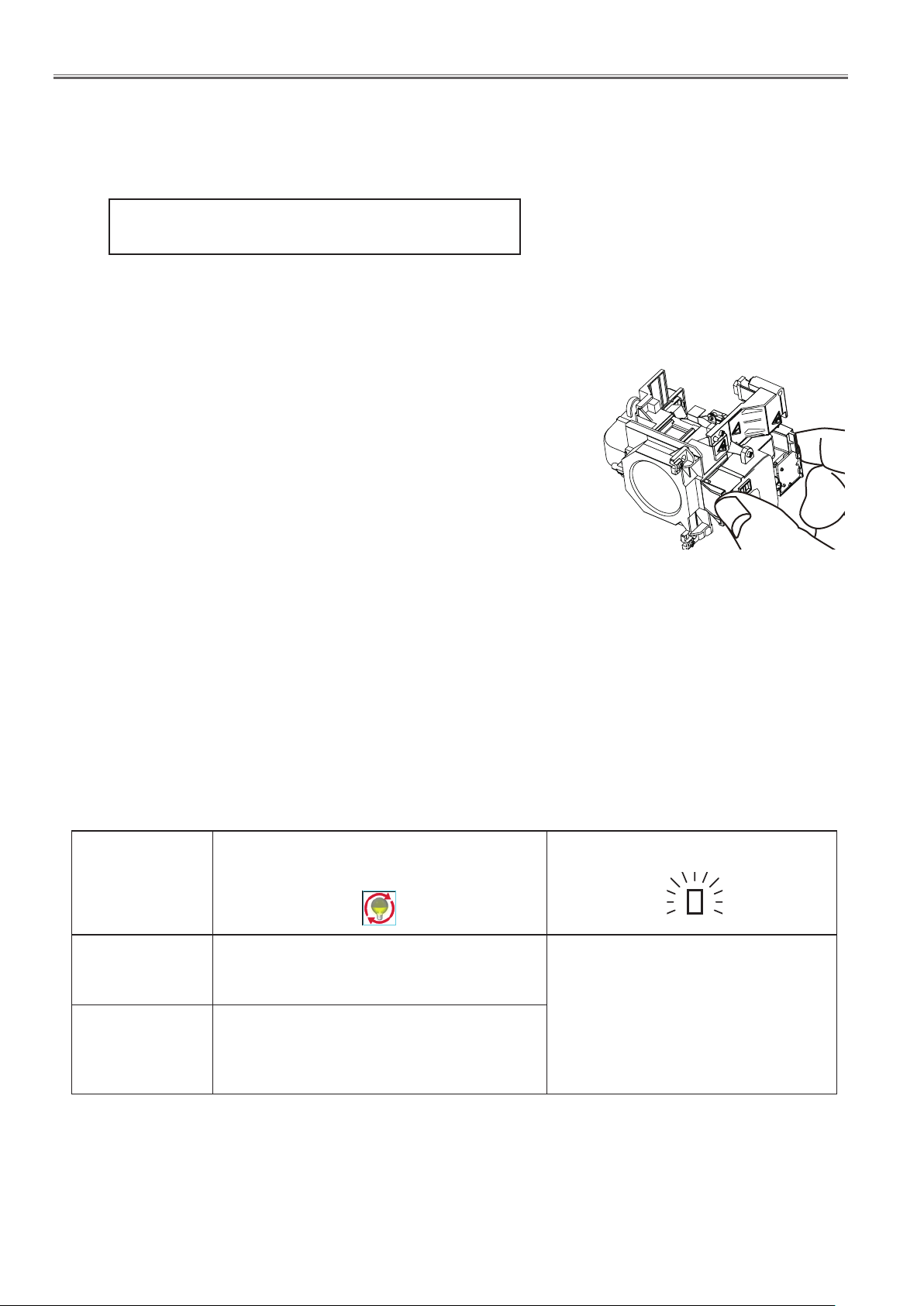
n When to replace the lamp unit
The lamp unit is a consumable component. Brightness decreases according to duration of usage, so periodical
replacement of the lamp unit is necessary. When the projection lamp of the projector reaches its end of life, the
lamp replacement icon appears on the screen and <LAMP> indicator lights yellow. Replace the lamp with a new
one promptly.
Lamp runtime
The message is displayed for 10 seconds. If
Over 3000 hours*
Over 3200 hours*
* 3200 hours of use is a rough guideline, but is not a guarantee. The lamp runtime differs depending on the setting of
"Lamp power" menu.
Note
•Thelampreplacementiconwillnotappearwhenthe[display]functionissetto[Off],orduring"Freeze".
you press any button within the 10 seconds,
the message disappears.
If the power is turned on without replacing
the lamp, the power automatically turns off
after approximately ten minutes to prevent the
malfunction of the projector.
On screen
Lamp replacement icon
Lights in yellow (even in stand-by
mode).
LAMP indicator
-15-
Maintenance
Replacing the lamp unit
CAUTION:
•When the projector is mounted on aceiling, do not
work with your face close to the projector.
•Attachthelampunitandthelampcoversecurely.
•Whenyouexperiencedifficultyininstallingthelamp,
remove it and try again. If you use force to install the
lamp, the connector may be damaged.
1) Turn off the projector. Unplug the AC power cord.
Wait at least 1 hour and make sure the lamp unit
and surroundings are cool.
2) Use a phillips screwdriver to loosen the lamp
cover fixing screw and remove the lamp cover.
•Removethe lampcoverbypullingitslowly toward
the direction of the arrow.
3) Use a phillips screwdriver to loosen the three
lamp unit fixing screws until the screws turn freely. hold the used lamp unit by its handles, and
pull it gently from the projector.
Lamp cover
Lamp cover
xingscrew
Lampunitxingscrews
4) Insert the new lamp unit in correct direction.
Tighten the three lamp unit fixing screws securely with a phillips screwdriver.
5) Attach the lamp cover, and tighten the lamp cover
fixing screw securely with a phillips screwdriver.
•Attach the lamp cover by pushing it slowly opposite
the direction of the arrow.
Attention
•When you replace the new lamp unit, the projector
resets the total usage time of the lamp unit automatically.
Handles
-16-
Maintenance
Counter
Projector 500H
Lamp
Normal 200H
Eco 300H
Corresponding value 425H
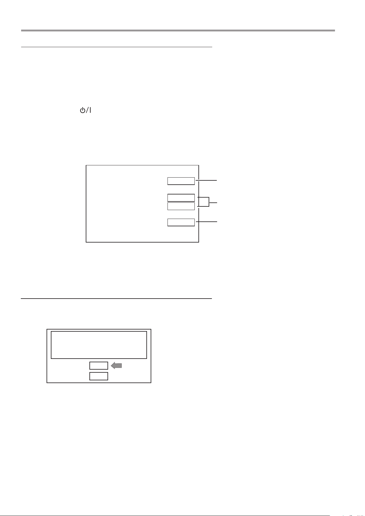
How to check lamp runtime
The LAMP indicator will light yellow when the lamp runtime (Corresponding value) reaches 3,000 hours. This is to
indicate that lamp replacement is required. The lamp runtime is calculated by using the below expression.
Lamp runtime (Corresponding value) = Tnormal + Teco x 0.75
Tnormal : used time in the Normal and Auto mode
Teco : used time in the Eco1 and Eco2 mode
You can check the lamp runtime following to the below procedure.
1 Press and hold the button on the projector or the POWER ON button on the remote control for more than 20
seconds.
2 The projector used time and lamp runtime will be displayed on the screen briefly as follows.
Projector used time
Cumulative lamp
operating time in
each mode.
lamp runtime
Warning message on the non-standard lamp used
If the non-standard lamp is used, the warning and confirmation messages will appear on the screen every startup.
Some of the functions are limited when the non-standard lamp is used in spite of the warning.
Since the lamp is not standard, projec-
tor failed to read lamp data.
Continue to use this lamp?
Yes
No
-17-
Maintenance
E
E
D
D
D
E
E
E
E
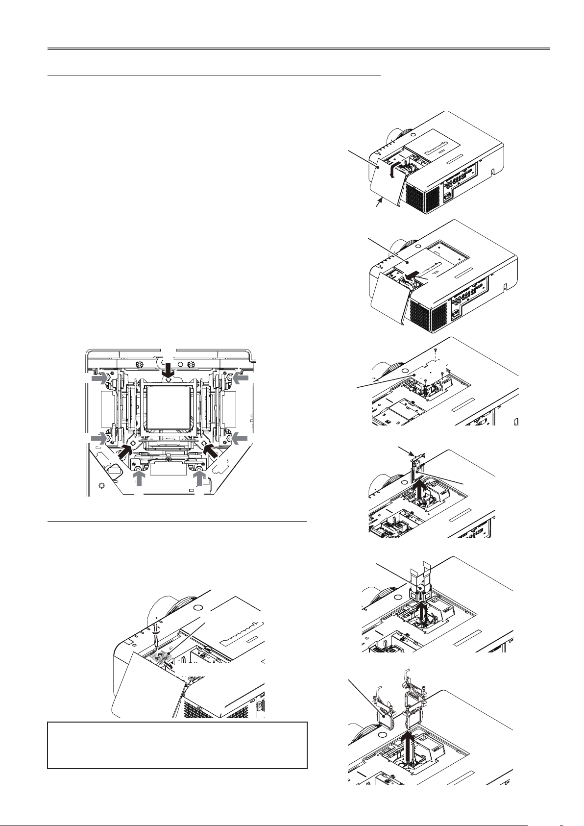
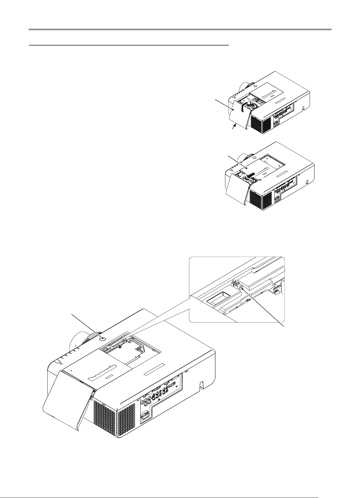
Quick maintenance
This projector provides a cabinet prism cover on the cabinet top to enhance the service maintenance. This enables
service personnel to align the optical adjustment or replace the optical parts without disassembly the cabinet top.
Loosen 1 screw-A on the lamp cover and slide it to
1
open (Fig. 1).
Lamp cover
Loosen 1 screw-B on the prism cover and slide it in the
2
arrow direction (Fig. 2).
Remove 2 screws-C(M3x6) and 1 screw-G(M3x10) to
3
take the prism cover shield (Fig.3) then Loosen 1 hex
screw-F and take the shutter assy off (Fig. 4).
Loosen 3 screws-D and take the LCD panel/prism assy
4
upward off (Fig. 5/Fig. 7).
Remove 2 screws-E on each stopper of the polarized
5
glass assy and take the polarized glass assy upward off
(Fig. 5/Fig. 7).
See chapter "Optical Parts Disassembly" for further information of the optical parts disassembly.
Fig. 7
Prism cover
Prism cover
shield
Fig. 1
A
B
Fig. 2
G
C
C
F
Shutter assy
Fig. 3
Setting the lamp cover switch to "Service"
When aligning the optical parts with the lamp cover open,
the projector cannot be turned on because the lamp cover
switch is off. Insert the flat screw driver into the opening on
the switch and set the lamp cover switch to "service" position
as shown in the figure below.
Lamp cover switch
"Service" position
After finishing the alignment, make sure that the lamp cover
switch is reset to its original position, and close the prism
cover and lamp cover securely.
Panel/prism
assy
Polarized glass assy
Fig. 4
Fig. 5
Fig. 6
-18-
Maintenance
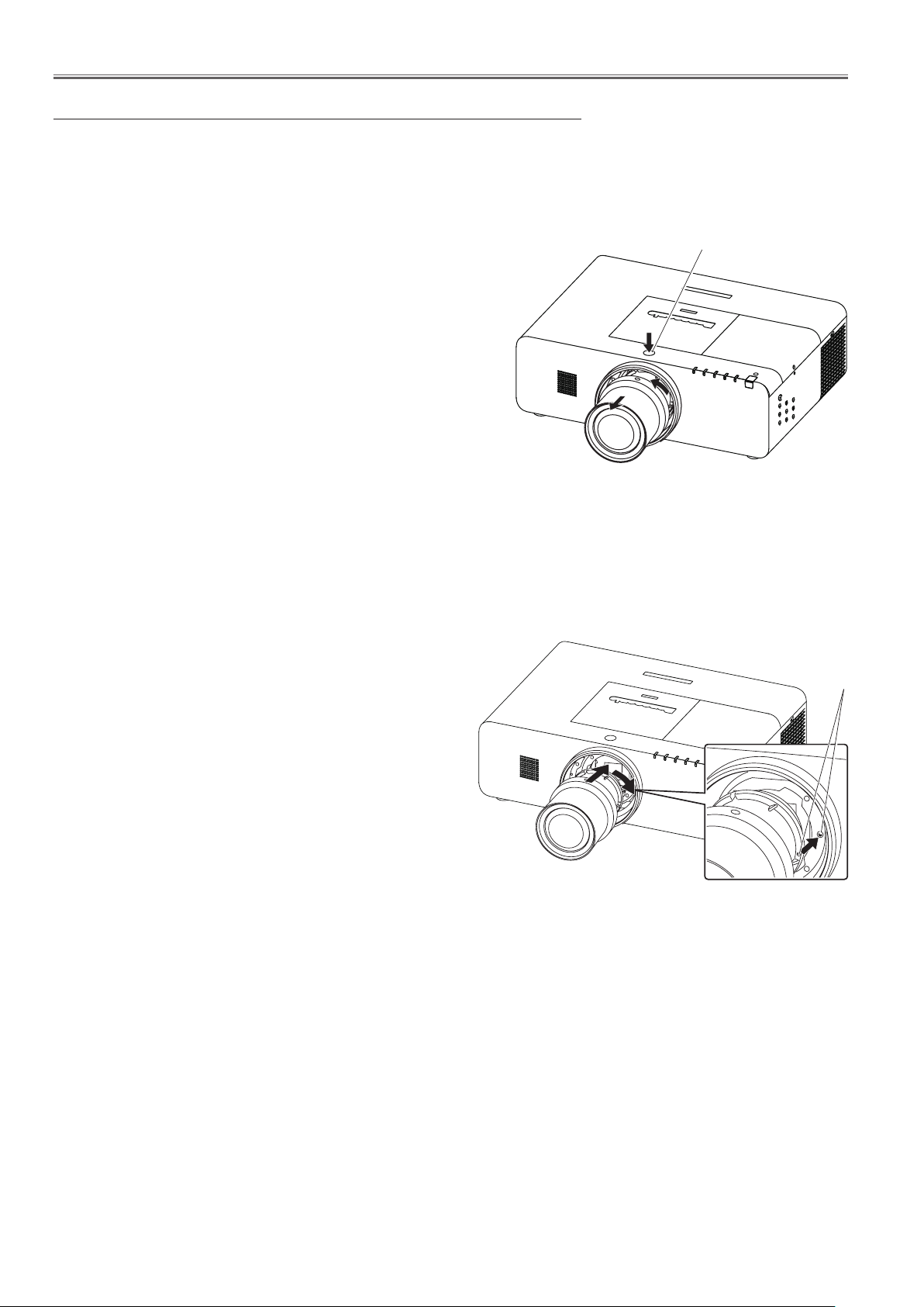
Removing and attaching the projection lens
When replacing the lens or using an optional lens, install the lens by following the instructions below. Ask the sales
dealerfordetailedinformationoftheoptionallensspecications.
Removing the lens
1. Press and hold the
button for more than 5 seconds to make the lens return
to the central position.
2. Turn off the projector and unplug the AC power cord.
3. While pressi ng th e len s rel ease button, ro tate the
pr ojection lens counterc lockwise , and remove the
projection lens.
Be careful when handling the lens. Do not drop.
ò
<LENS>
button or
<LENS SHIFT>
Lens release button
Attaching the lens to the projector
1. Remove the lens mount cove
2. Fit the lens to the projector by aligning the red dot on the
lens with the red dot of the projector.
3. Slowly turn the lens clockwise until it clicks. Make sure
that the lens is fully inserted to the projector.
Do not press the lens release button when attaching the lens.
ò
r.
Red dots
-19-
Maintenance
Using the lens antitheft screw
This projector provides a lens antitheft screw to protect the projection lens stolen from a suspicious person. Mount
the lens antitheft screw by following the instructions below.
Mounting the lens antitheft screw
Loosen a screw-A on the lamp cover and slide it to
1
open (Fig. 1).
Loosen a screw-B on the prism cover and slide it in
2
the arrow direction (Fig. 2).
Insert the lens antitheft screw onto the screw hole
3
on the cabinet top and turn it until the lens release
button is locked (Fig. 3).
Close the prism cover and tighten the screw-B, and
4
close the lamp cover and tighten the screw-A.
Check that the lens release button is locked to protect the projection lens removing.
Note: Be careful not to drop the lens antitheft screw into
the opening of the projector when mounting the
screw.
Lamp cover
Prism cover
A
B
Fig. 1
Fig. 2
Lens release button
Lens antitheft screw
Fig. 3
-20-
Maintenance
Cleaning
After long periods of use, dust and other particles will accumulate on the LCD panel, prism, mirror, polarized glass,
lens, etc., causing the picture to darken or color to blur. If this occurs, clean the inside of optical unit.
Remove dust and other particles using air spray. If dirt cannot be removed by air spray, disassemble and clean the
optical unit.
Cleaning with air spray
Remove the cabinet top following to “Mechanical Disassembly”. Clean up the LCD panel and polarizing plate by using
the air spray from the cabinet top opening.
Caution:
Use a commercial (inert gas) air spray designed for cleaning camera and computer equipment. Use a resin-based
nozzle only. Be very careful not to damage optical parts with the nozzle tip. Never use any kind of cleanser on the unit.
Also, never use abrasive materials on the unit as this may cause irreparable damage.
Disassembly cleaning
Disassembly cleaning method should only be performed when the unit is considerable dirty and cannot be sufficiently
cleaned by air spraying alone.
Be sure to readjust the optical system after performing disassembly cleaning.
1. Remove the cabinet top and main units following to “Mechanical Disassembly”.
2. Remove the optical base top following to “Optical Unit Disassembly”. If the LCD panel needs cleaning, remove
the LCD panel unit following to “LCD panel replacement”.
3. Clean the optical parts with a soft cloth. Clean extremely dirty areas using a cloth moistened with alcohol.
Caution:
The surface of the optical components consists of multiple dielectric layers with varying degrees of refraction. Never
use organic solvents (thinner, etc.) or any kind of cleanser on these components.
Since the LCD panel is equipped with an electronic circuit, never use any liquids (water, etc.) to clean the unit. Use of
liquid may cause the unit to malfunction.
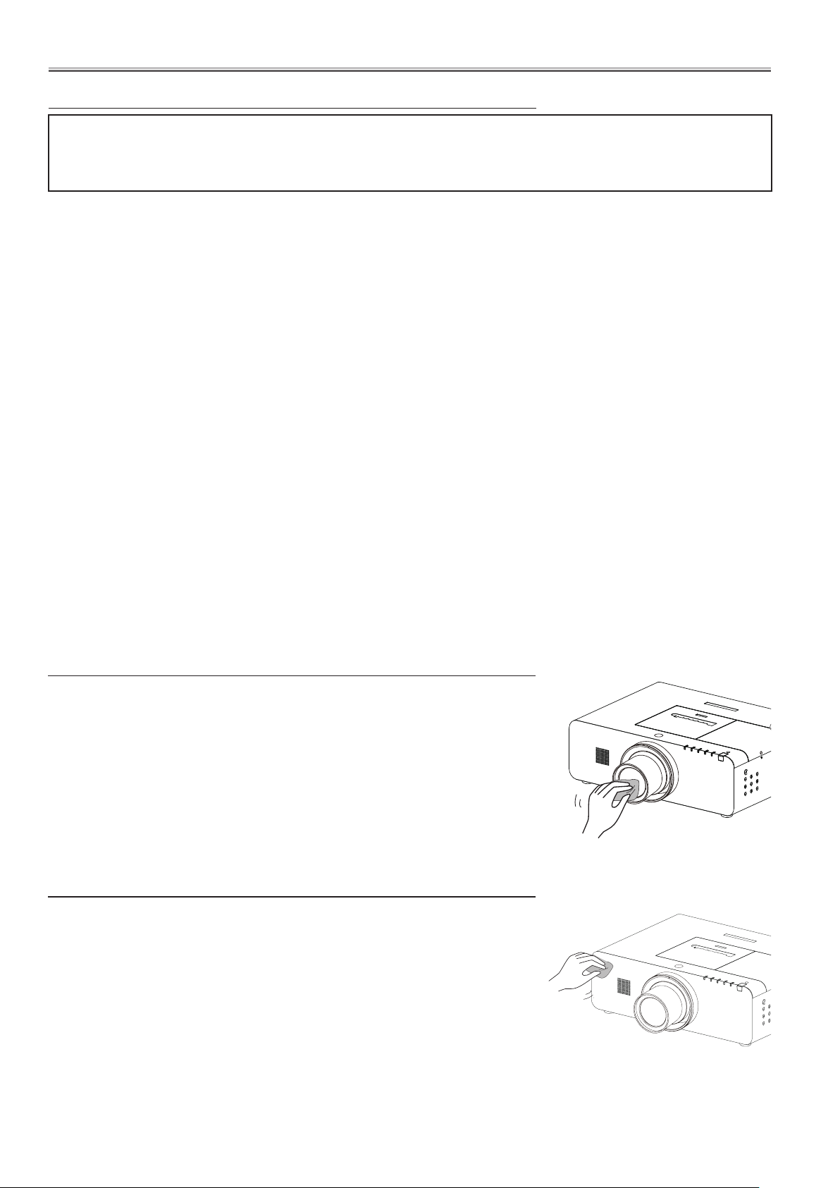
Cleaning the projection lens
Unplug the AC power cord before cleaning.
Gently wipe the projection lens with a cleaning cloth that contains a small
amount of non-abrasive camera lens cleaner, or use a lens cleaning paper or
commercially available air blower to clean the lens.
Avoid using an excessive amount of cleaner. Abrasive cleaners, solvents, or
other harsh chemicals might scratch the surface of the lens.
Cleaning the projector cabinet
Unplug the AC power cord before cleaning.
Gently wipe the projector body with a soft dry cleaning cloth. When the cabinet
is heavily soiled, use a small amount of mild detergent and finish with a soft dry
cleaning cloth. Avoid using an excessive amount of cleaner. Abrasive cleaners,
solvents or other harsh chemicals might scratch the surface of the cabinet.
When the projector is not in use, put the projector in an appropriate carrying
case to protect it from dust and scratches.
-21-
Security Function Notice
This projector provides security functions such as "Key lock", "PIN code lock" and "Logo PIN code lock". When the
projector has set these security function on, you are required to enter correct PIN code to use the projector. If you
do not know the correct PIN code to the projector, the projector can no longer be operated or started. In this case,
you must reset those function first according to the resetting procedure described below and then check up on the
projector.
Function Description
Locks operation of the top control or the remote control.
Key lock
PIN code lock
Logo PIN code lock
If the Key lock is enabled with top control lock, the projector can no longer be started.
Initial setting: Key lock function is disabled
Prevents the projector from being operated by an unauthorized person.
Initial code: "1234"
Prevents an unauthorized person for changing the
start-up logo on the screen.
Initial code: "4321"
Resetting procedure
1. Disconnect the AC power cord from the AC outlet.
2. As pressing the ENTER button, connect the AC power cord into an AC outlet again.
3. Keep pressing the ENTER button and then press the button.
4. Release the button first and then release the ENTER button.
- The PIN code lock and Logo PIN code lock will be reset as the initial PIN code at the factory and
the key lock function is disabled.
Please refer to the owner's manual for further information of the security functions.

-22-
Standby Mode Notice
This projector provides 3 types of standby mode, Normal standby mode, Eco standby mode and Network standby
mode. According to the standby mode "Normal", "Eco" or "Network", several functions are restricted as shown in the
table below. To change the standby mode, use the projector's menu "Setting".
Normal ............ Normal standby mode.
Network .......... Supply the power to the network function even after turning off the projector. You can turn on /off
the projector via network, modify network environment, and receive an e-mail about projector status
while the projector is powered off.
Eco ................. Select "Eco" when you do not use the projector via network. The projector's network function will
stop when turning off the projector.
When "Eco" is selected, several functions will be restricted.
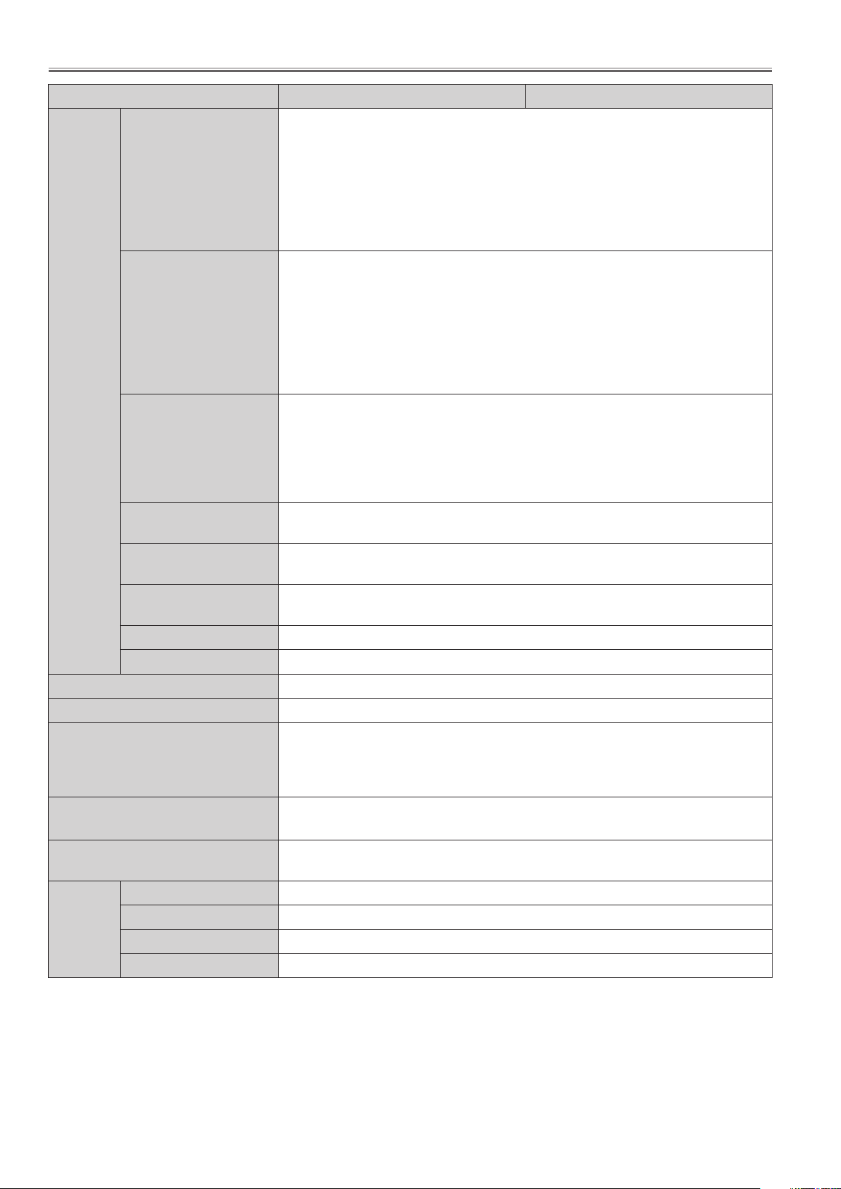
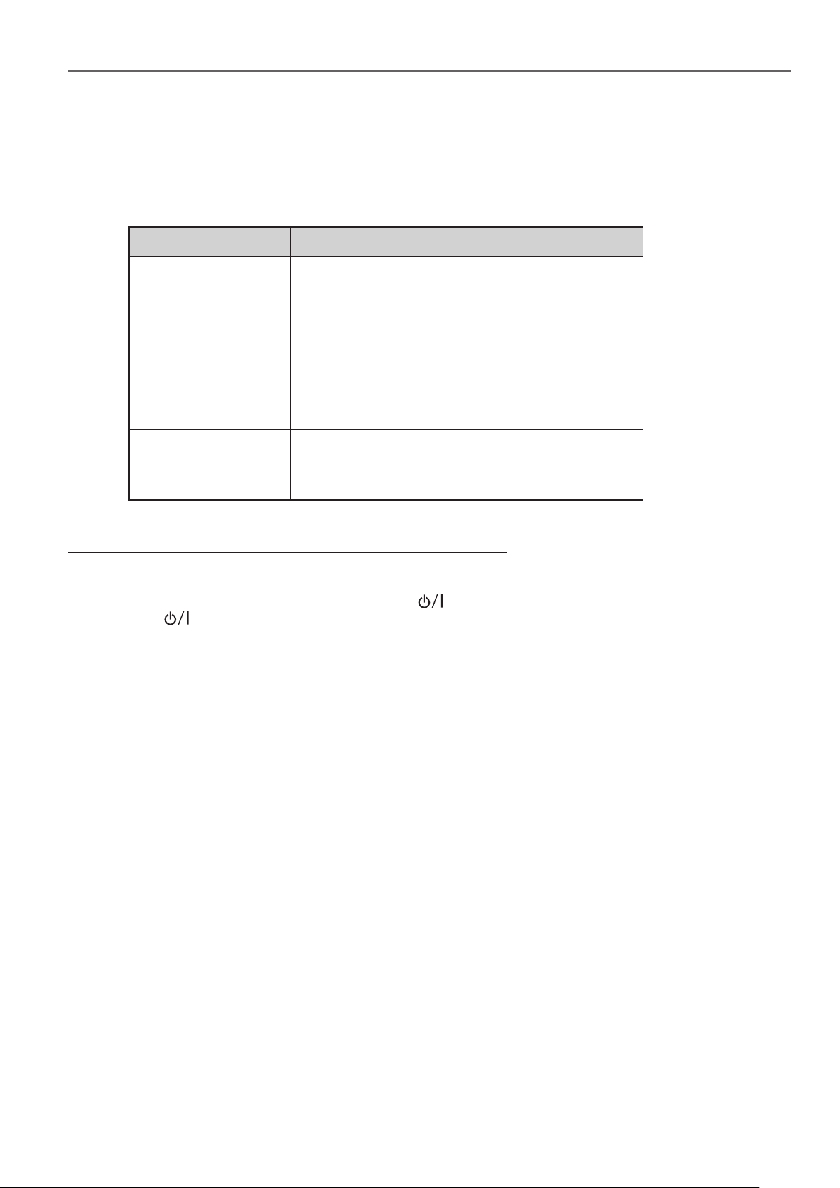
Restricted function in the standby mode
Function Normal Eco Network
Network
Serial command control
Monitor out
Audio out
RC sensor setting
*1 When "Eco" is selected, all of the infrared remote receivers, top, front or rear are activated in the eco
standby mode regardless of the RC sensor setting.
✔
✔
✔
✔
✔ ✔
--
--
✔
✔
-- --
-- --
*1
✔
-23-
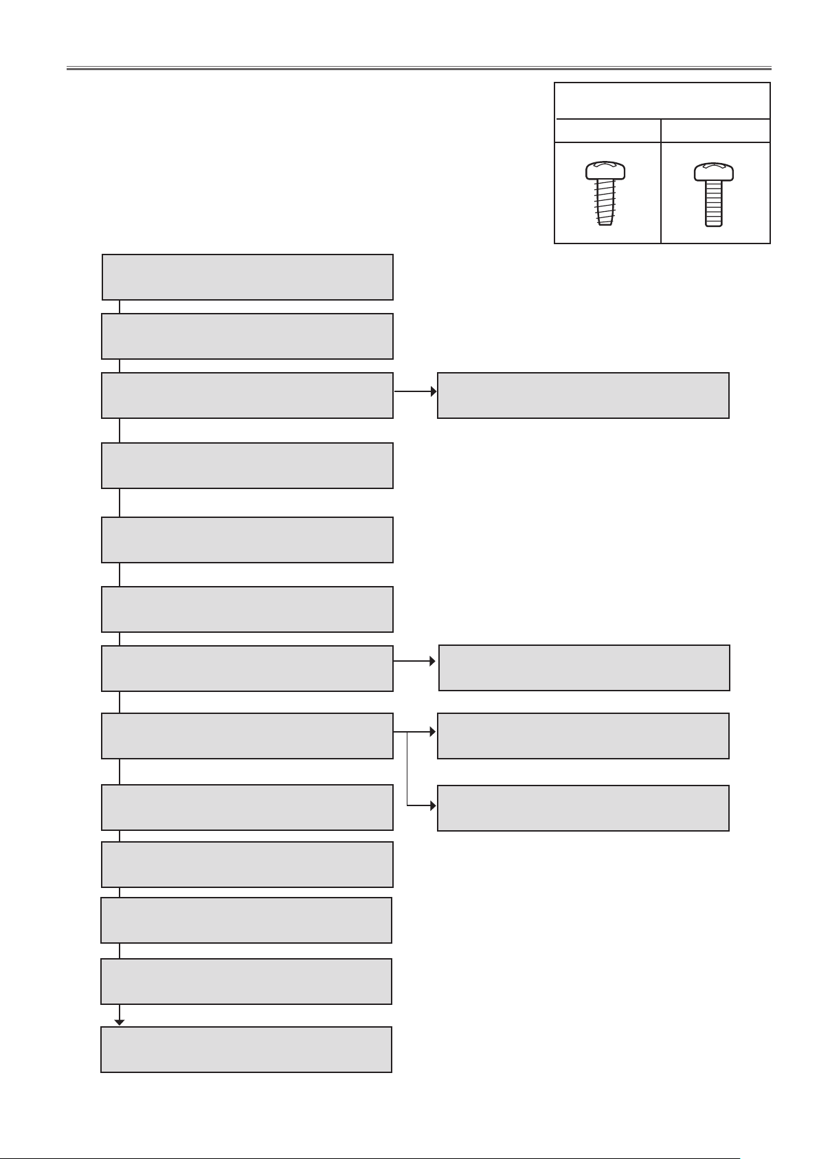
Mechanical Disassembly
Mechanical disassembly should be made following procedures in numerical order.
Following steps show the basic procedures, therefore unnecessary step may
be ignored.
Caution:
The parts and screws should be placed exactly the same position as the original
otherwise it may cause loss of performance and product safety.
1. Lamp cover and prism cover removal
2. Cabinet top removal
3. Fan (FN905) and main&AV board removal
4. Shutter and sensor C board removal
3-1. Main board and A/V board removal
Screws expression
(Type Diameter x Length) mm
T type M type
5. Lamp, lamp cover and ID connect board
removal
6. Projection lens removal
7. Optical unit removal
8. Power box and thermal SW (SW902)
removal
9. Control board and fans (FN902, FN903,
FN904) removal
10. Filter assy removal
11. Fans (FN908, FN909, FN910) removal
7-1. Lens shift assy and Iris assy removal
8-1. Thermal fuse replacing
8-2. Power box disassembly and fan
(FN901) removal
12. Fans (FN906, FN907, FN911) and
speaker removal
13. Cable reforming
-24-
Mechanical Disassembly
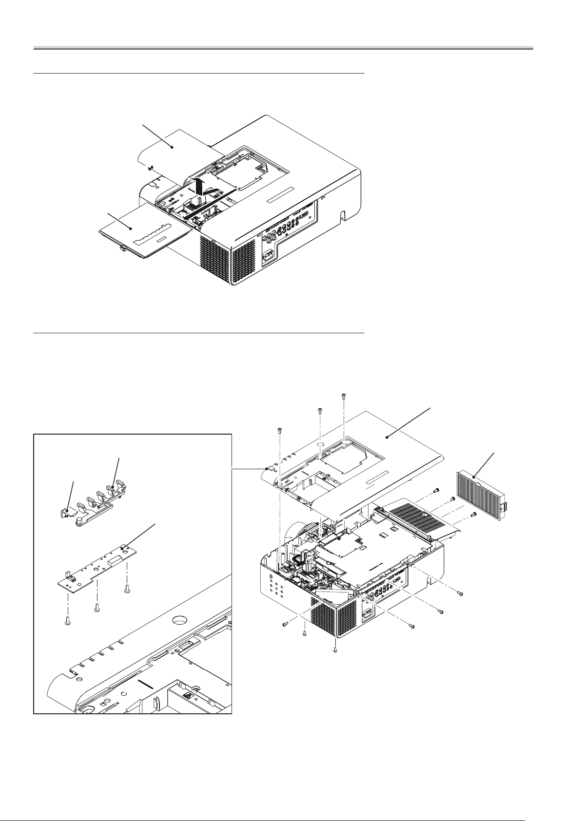
1. Lamp cover and prism cover removal
1. Loosen 1 screw-A and remove the lamp cover upward off.
2. Loosen 1 screw-B and remove the prism cover by sliding it in the arrow
direction.
Lamp cover
A
Prism cover
B
2. Cabinet top removal
1. Open the filter cover and remove the air filter unit.
2. Remove 12 screws-A (M3x8) to take the cabinet top assy upward off.
A
A
A
LED decoration
RC front
window
F/T RC+LED
board
T3x8
T3x8
T3x8
A
A
Cabinet top assy
Air filter unit
A
A
A
A
A
A
A
-25-
Mechanical Disassembly
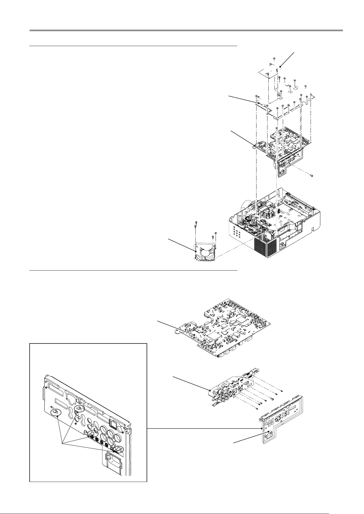
3. Fan (FN905) and main&AV board removal
1. Remove 1 screw-A (M3x10) and 3 screws-B (T3x10) to take the fan (FN905)
upward off.
2. Remove 2 screws-C(M3x6) and 1 screw-J(M3x10) to take the prism cover
shield off.
3. Remove 12 sccrews-D(M3x10) , 1 screw-E(T3x10) and 3 sccrews-G(M3x6)
to take the main board shield top off.
4. Remove 1 screw-H(M3x10)and 1 screws-F(M3x8)
and then remove the main&AV board.
Main board
shield top
D
E
D
G
D
Prism cover
shield
D
D
D
D
D
G
G
D
J
C
C
D
D
D
Main&AV board
B
B
Fan (FN905)
A
B
3-1.Main board and A/V board removal
1. Release the 4 hooks to remove the AV panel .
2. Remove 6 hex-screws-B and 1 screw A (M3x8) to remove the AV board
from the main board.
H
F
Hooks
Main board
AV board
AV panel
B
B
A
B
B
B
B
-26-
Mechanical Disassembly
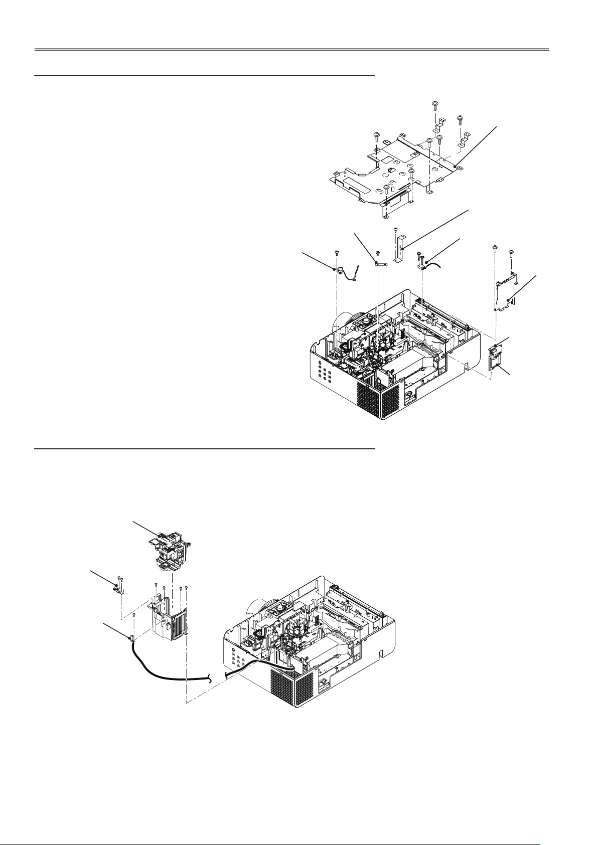
4. Shutter and sensor C board removal
1.
Remove 3 screws-A (M3x10)
shield bottom.
2. Loosen 1 hex screw-C and pull the shutter assy upward.
3. Remove 1 screw-D (T3x8) to take the sensor C board off.
4. Remove 1 screw-E (T3x8) to take the lamp cover switch off.
5. Remove 2 screws-F (T3x14) to take the wind sensor (S901) off.
6. Remove 1 screws-G (T3x10) to take the connect shield,
and remove 2 screw-H (T3x10) to pull the net shield
upward.
and 4 screw-B (T3x10)
to take the main board
B
B
Main board
B
A
B
shield bottom
A
A
Connect shield
Sensor C board
Lamp cover switch
E
5. Lamp, lamp cover and ID connect board removal
1. Loosen 3 screws-A and pull the lamp assy upward.
2. Remove 4 screws-B (T3x8) to take the lamp house holder upward off.
3. Remove 2 screws-C (T3x8) to take the ID connect board.
4. Remove 1 screw-D (T3x10) to remove the ballast socket.
G
D
F
Wind sensor (S901)
H
H
Net shield
C
Shutter assy
ID connect
board
Ballast
socket
Lamp assy
C
A
A
C
B
B
A
B B
D
-27-
Mechanical Disassembly
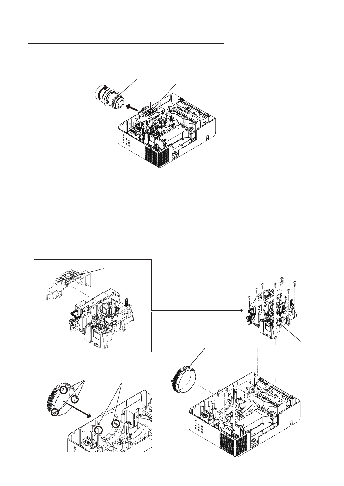
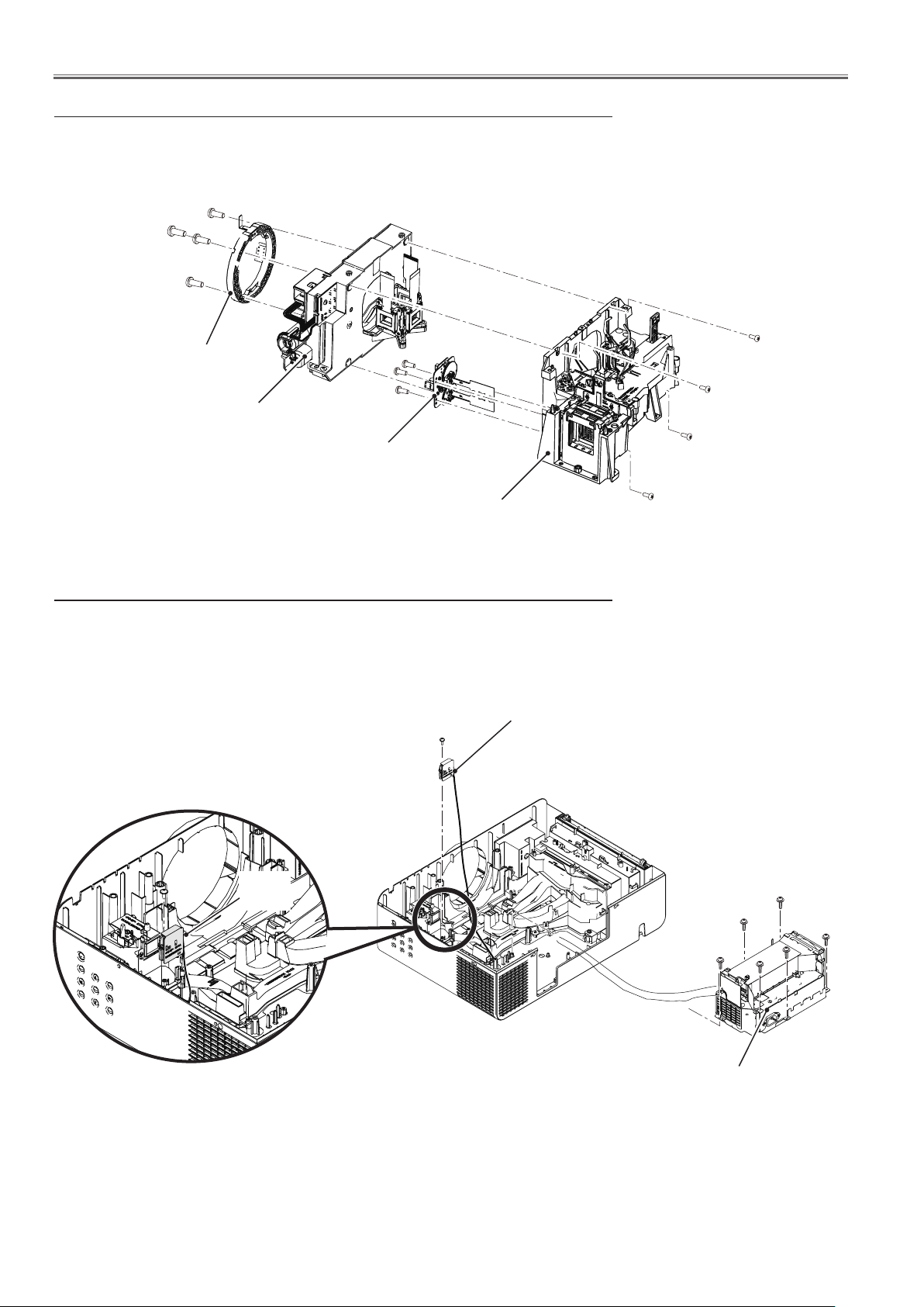
6. Projection lens removal
1. Press and hold the lens release button and turn the projection lens counterclockwise until it stops and put it out slowly.
Projection lens
Lens release button
7. Optical unit removal
1. Remove 2 screws-A (T3x8)and 7 screws-B (T4x10) and remove the optical
unit assy and lens shift assy.
2. Loose the lens cover top.
3. Remove the front ring cover by pressing it from back.
Lens cover top
Guides
Grooves
Front ring cover
B
B
B
B
A
B
B
B
A
Optical unit and
Lens shift assy
-28-
Mechanical Disassembly
7-1. Lens shift assy and Iris assy removel
1. Remove 4 screws-A (M3x8) to take the lens shift assy off.
2. Remove 4 screws-B (M3x14) to take the lens mount off.
3. Remove 3 screws-C (T3x8) to take the Iris assy.
B
B
B
B
Lens mount
C
C
C
Lens shift assy
Iris assy
Optical unit assy
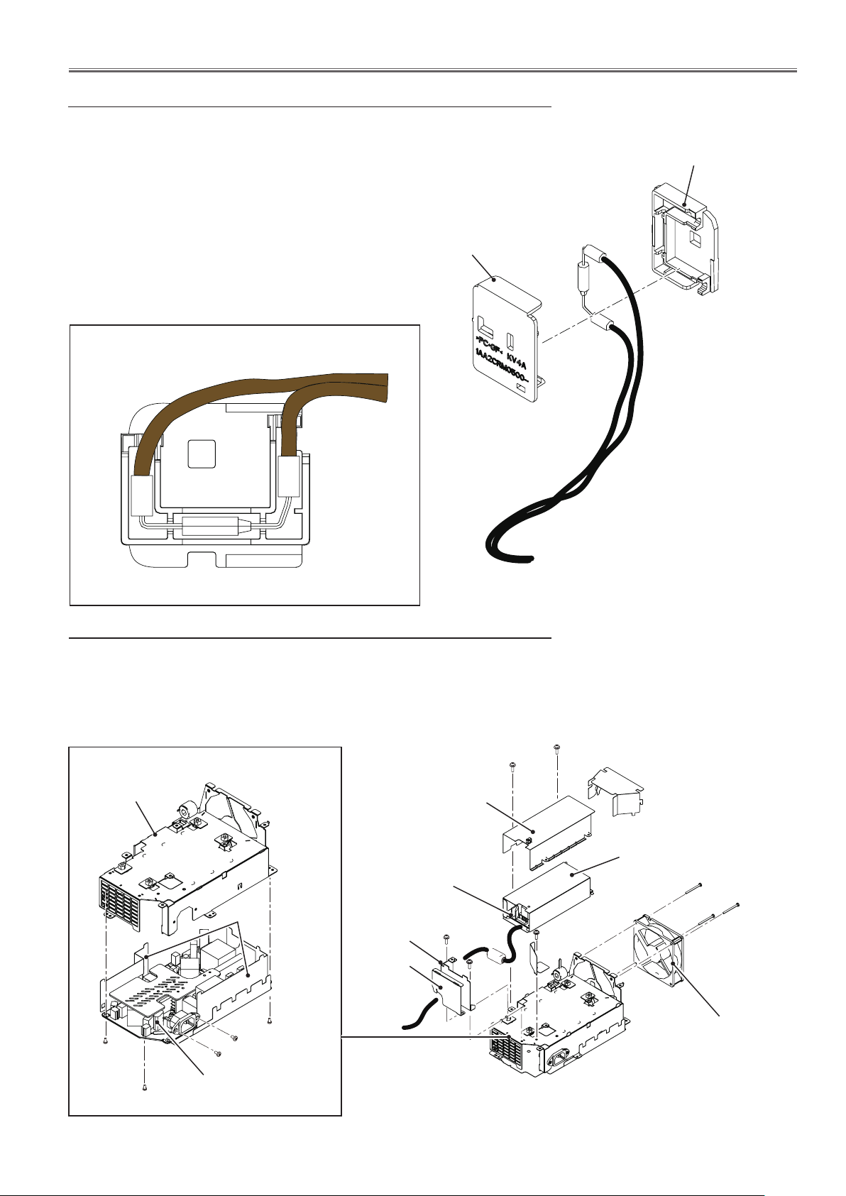
8. Power box and thermal fuse (SW902) removal
1. Remove 3 screws-A (M3x10) and 3 screws-B (T3x10) to remove the Power
Box assy.
2. Remove 1 screw-C (T3x8) and pull the SW902 upward off.
C
Thermal fuse(SW902)
A
A
A
A
SW902
B
A
A
Power box assy
B
A
B
-29-
Mechanical Disassembly
8-1. Thermal fuse replacing
1. Remove the thermal fuse spacer from the thermal fuse mounting.
2. Remove the thermal fuse(SW902).
3. Mount the thermal fuses as shown in the figure below.
Thermal fuse spacer
Top view of the fuse mounting
Thermal fuse mounting
8-2. Power box disassembly and fan (FN901) removal
1. Remove 2 screw-A (M3x10) to remove the ballast shield top.
2. Remove 2 screws-B (M3x10) to take the Holder. then remove 1 screw-D
(M3x10) to take the ballast board off.
3. Remove 3 screws-E (T3x28) to take the fan (FN901) off.
A
A
Power holder
M3x10
Spacer
M3x10
M3x6
Ballast shield top
Ballast board
Holder
Spacer
B
B
D
Spacer
E
E
FN901
E
M3x10
Power board
-30-
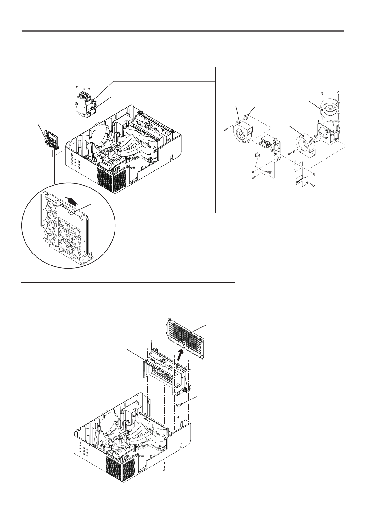
Mechanical Disassembly
9. Control board and fans (FN902,FN903,FN904) removal
1. Remove 3 screws-A (T3x8) to take the lamp fan assy off.
2. Pull the holder on the control board up to release the hook and remove the
Control board assy upward off.
A
A
A
T3x12
T3x12
Control board assy
Holder
10. Filter assy removal
Lamp fan assy
FN903
T3x22
T3x12
T3x12
Spacer
FN902
FN904
T3x12
T3x8
T3x8
1. Remove the filter cover by pulling it outside.
2. Remove 4 screws-A (T3x8) and 1 screw-B (M3x8) and pull the filter box
assy upward off.
3. Remove 1 screw-C (T3x6) to remove the filter switch(SW1891).
Filter cover
A
Filter box assy
A
A
A
Filter switch(1891)
C
B
 Loading...