

Panasonic PT-DZ8700U, PT-DS8500U, PT-DW8300U User Manual

Phone: 800.894.0412 - Fax: 888.723.4773 - Web: www.clrwtr.com - Email: info@clrwtr.com
HarmonicGuard® Series Drive-Applied Harmonic Filter
Installation, Operation, and Maintenance Manual

Table of Contents
Phone: 800.894.0412 - Fax: 888.723.4773 - Web: www.clrwtr.com - Email: info@clrwtr.com
Introduction.........................................................................................................................2
Receiving Inspection and Storage.......................................................................................4
Pre-installation Planning.....................................................................................................5
Installation Guidelines........................................................................................................6
HG7 Harmonic Filter Operation.........................................................................................8
Installation.........................................................................................................................9
Maintenance and Service...................................................................................................10
Product Description...........................................................................................................14
Drawings..........................................................................................................................17
Standard Filter (ST)...........................................................................................................23
Contactor Option (STC).....................................................................................................24
Power Monitor Package Option (XM)................................................................................25
HG7 “XM” Option Operation............................................................................................29
The HG2TM Protection Monitor.........................................................................................30
Component Package Option (CP).....................................................................................47
Installation........................................................................................................................49
i HG7 I, O, & M Manual
Introduction
Phone: 800.894.0412 - Fax: 888.723.4773 - Web: www.clrwtr.com - Email: info@clrwtr.com
INTRODUCTION
Safety Instructions Overview
This section provides the safety instructions which must be followed when installing, operating, and
servicing the HG7 harmonic filter. If neglected, physical injury or death may follow, or damage may
occur to the filter or equipment connected to the HG7 harmonic filter. The material in this chapter must
be read and understood before attempting any work on, or with, the product.
The HG7 harmonic filter is intended to be connected to the input terminals of one or more adjustable
speed drives. Three-phase power is connected to the input terminals of the HG7 and power is supplied
to the drive or drives through the HG7. The instructions, and particularly the safety instructions, for the
drives, motors and any other related equipment must be read, understood and followed when working
on any of the equipment.
Warnings and Cautions
This manual provides two types of safety instructions. Warnings are used to call attention to
instructions, which describe steps, which must be taken to avoid conditions, which can lead to a
serious fault condition, physical injury or death.
Cautions are used to call attention to instructions that describe steps that must be taken to avoid
conditions that can lead to a malfunction and possible equipment damage.
Warnings
Readers are informed of situations that can result in serious physical injury and/or serious damage to
equipment with warning statements highlighted by the following symbols:
Warning Dangerous Voltage Warning: warns of situations in which a
high voltage can cause physical injury and/or damage
equipment. The text next to this symbol describes ways to
avoid the danger.
Warning General Warning: warns of situations that can cause physical
injury and/or damage equipment by means other than
!
Warning Electrostatic Discharge Warning: warns of situations in which
electrical. The text next to this symbol describes ways to avoid
the danger.
an electrostatic discharge can damage equipment. The text next
to this symbol describes ways to avoid the danger.
Cautions
Readers are informed of situations that can lead to a malfunction and possible equipment damage with
caution statements:
Caution General Caution: identifies situations that can lead to a
malfunction and possible equipment damage. The text
describes ways to avoid the situation.
INTRODUCTION HG7 I, O, & M Manual
2
INTRODUCTION
Phone: 800.894.0412 - Fax: 888.723.4773 - Web: www.clrwtr.com - Email: info@clrwtr.com
General Safety Instructions
These safety instructions are intended for all work on the HG7. Additional safety instructions are
provided at appropriate points on other sections of this manual.
Warning
!
Warning
!
Warning
!
Warning
Warning
Warning
Be sure to read, understand and follow all safety instructions.
Only qualified electricians should carry out all electrical
installation and maintenance work on the HG7 harmonic filter.
All wiring must be in accordance with the National Electrical
Code (NEC) and/or any other codes that apply to the
installation site.
Disconnect all power before working on the equipment.
Do not attempt any work on a powered HG7 filter.
The HG7 harmonic filter, drive, motor, and other connected
equipment must be properly grounded.
After switching off the power, always allow 5 minutes for the
capacitors in the HG7 filter and in the drive to discharge before
working on the HG7, the drive, the motor, or the connecting
wiring. It is a good idea to check with a voltmeter to make sure
that all sources of power have been disconnected and that all
capacitors have discharged before beginning work.
INTRODUCTION HG7 I, O, & M Manual
3

INTRODUCTION
Phone: 800.894.0412 - Fax: 888.723.4773 - Web: www.clrwtr.com - Email: info@clrwtr.com
Receiving Inspection and Storage
Thank you for selecting the HG7 Drive-Applied Harmonic Filter. TCI has produced this filter for use
in many variable speed drive applications that require input power line harmonic current reduction.
This manual describes how to install, operate and maintain the HG7 harmonic filter.
Receiving Inspection
The HG7 harmonic filter has been thoroughly inspected and functionally tested at the factory and
carefully packaged for shipment. When you receive the unit, you should immediately inspect the
shipping container and report any damage to the carrier that delivered the unit. Verify that the part
number of the unit you received is the same as the part number listed on your purchase order.
TCI Limited Warranty Policy
TCI, LLC (“TCI”) warrants to the original purchaser only that its products will be free from defects in materials
and workmanship under normal use and service for a period originating on the date of shipment from TCI and
expiring at the end of the period described below:
Product Family Warranty Period
KLR, KDR For the life of the drive with which they are installed.
KLC, KLCUL, KMG,
V1k
HG7, KH, 3H, KRF Three (3) years from the date of shipment.
KCAP, KTR, KMP Five (5) years from the date of shipment.
All Other Products
The foregoing limited warranty is TCI’s sole warranty with respect to its products and TCI makes no other
warranty, representation, or promise as to the quality or performance of TCI’s products. THIS EXPRESS
LIMITED WARRANTY IS GIVEN IN LIEU OF AND EXCLUDES ANY AND ALL EXPRESS OR IMPLIED
WARRANTIES INCLUDING, WITHOUT LIMITATION, ANY IMPLIED WARRANTY OF
MERCHANTABILITY OR FITNESS FOR A PARTICULAR PURPOSE.
This warranty shall not apply if the product was:
a) altered or repaired by anyone other than TCI;
b) applied or used for situations other than those originally specified; or
c) subjected to negligence, accident, or damage by circumstances beyond TCI’s control, including but not
limited to, improper storage, installation, operation, or maintenance.
If, within the warranty period, any product shall be found in TCI’s reasonable judgment to be defective, TCI’s
liability and the Buyer’s exclusive remedy under this warranty is expressly limited, at TCI’s option, to (i) repair or
replacement of that product, or (ii) return of the product and refund of the purchase price. Such remedy shall be
Buyer’s sole and exclusive remedy. TCI SHALL NOT, IN ANY EVENT, BE LIABLE FOR INCIDENTAL
DAMAGES OR FOR CONSEQUENTIAL DAMAGES INCLUDING, BUT NOT LIMITED TO, LOSS OF
INCOME, LOSS OF TIME, LOST SALES, INJURY TO PERSONAL PROPERTY, LIABILITY BUYER
INCURS WITH RESPECT TO ANY OTHER PERSON, LOSS OF USE OF THE PRODUCT OR FOR ANY
OTHER TYPE OR FORM OF CONSEQUENTIAL DAMAGE OR ECONOMIC LOSS.
The foregoing warranties do not cover reimbursement for removal, transportation, reinstallation, or any other
expenses that may be incurred in connection with the repair or replacement of the TCI product.
The employees and sales agents of TCI are not authorized to make additional warranties about TCI’s products.
TCI’s employees and sales agents oral statements do not constitute warranties, shall not be relied upon by the
Buyer, and are not part of any contract for sale. All warranties of TCI embodied in this writing and no other
warranties are given beyond those set forth herein.
TCI will not accept the return of any product without its prior written approval. Please consult TCI Customer
Service for instructions on the Return Authorization Procedure.
not to exceed 18 months from the date of shipment.
not to exceed 18 months from the date of shipment.
One (1) year of useful service,
One (1) year of useful service,
Storage Instructions
If the HG7 harmonic filter is to be stored before use, be sure that it is stored in a location that conforms
to published storage humidity and temperature specifications stated in Table 2 (HG7 Harmonic Filter
Technical Specifications). Store the unit in its original packaging.
INTRODUCTION HG7 I, O, & M Manual
4
INTRODUCTION
Phone: 800.894.0412 - Fax: 888.723.4773 - Web: www.clrwtr.com - Email: info@clrwtr.com
Pre-installation Planning
Verify the Application
HG7 Ratings
Make sure that the HG7 harmonic filter is correct for the application. The voltage ratings of the filter
must match the input voltage rating of the connected drive. The horsepower and current ratings of the
filter must be adequate for the connected load. The kVar rating of the HG7 filter should be 30% of the
horsepower rating for 3-phase diode bridge rectifier loads such as PWM AC drives.
Select a Suitable Location
Environment
Locating the HG7 in a suitable environment will help assure proper performance and a normal
operating life. Refer to the environmental specifications listed in Table , marked on the unit's
nameplate and/or noted on the drawings furnished with the unit.
Warning
The unit must be installed in an area where it will not be exposed to:
♦ Direct sunlight
♦ Rain or dripping liquids (unless filter is in a 3R enclosure)
♦ Corrosive liquids or gasses
♦ Explosive or combustible gases or dust
♦ Excessive airborne dirt and dust
♦ Excessive vibration
Unless specifically labeled as approved for such use, this equipment is not
suitable for use in an explosive atmosphere or in a "Hazardous (Classified)
Location" as defined in article 500 of the National Electrical code.
Working Space
Provide sufficient access and working space around the unit to permit ready and safe installation,
operation and maintenance. Make sure that the installation conforms to all working space and
clearance requirements of the National Electrical Code (NEC) and/or any other applicable codes.
Provide sufficient unobstructed space to allow cooling air to flow through the unit.
Mounting an Open Panel Unit
If you are mounting an open panel unit in your own enclosure, you must provide an enclosure that is
adequately sized and ventilated sufficiently to prevent overheating. The rating and dimension tables for
open panel units list the watts of heat loss that is dissipated by the HG7 harmonic filter. The maximum
temperature of the air around the HG7 filter capacitors and Protection Monitor should not exceed 50°C
(122°F).
Power Wiring
When selecting a mounting location for the HG7 filter, plan for the routing of the power wiring.
Route the conduit and wiring from the power source to the filter and then to the variable speed drive.
The HG7 is provided with internal fuses. Additional fuses may be required at the connecting point to
protect the tap conductors. Refer to the National Electrical Code (NEC) and/or any other applicable
codes.
INTRODUCTION HG7 I, O, & M Manual
5

INTRODUCTION
Phone: 800.894.0412 - Fax: 888.723.4773 - Web: www.clrwtr.com - Email: info@clrwtr.com
Installation Guidelines
Mounting
The HG7 must be mounted vertically on a smooth, solid surface, free from heat, dampness, and
condensation.
Wiring
Cable Entry Locations
The enclosed HG7 harmonic filters are not provided with enclosure wiring knockouts. A selection can
be made at the time of installation. Typical or recommended cable entry locations are shown in the
drawings section of this manual.
Field Wiring Connection Terminals
Compression type terminals are provided for all field wiring connections. The control circuit terminals
will accommodate 18 AWG to 10 AWG wire and should be tightened to 7 lbs. - in. torque. The wire
size capacity ranges and tightening torque for the grounding and power terminals are listed in the
drawings and other information shipped with the unit.
INTRODUCTION HG7 I, O, & M Manual
6
INTRODUCTION
Phone: 800.894.0412 - Fax: 888.723.4773 - Web: www.clrwtr.com - Email: info@clrwtr.com
Grounding
The HG7 panel equipment-grounding lug must be connected to the ground of the wiring system. The
equipment grounding connection must conform to the requirements of the National Electric Code
(NEC) and/or any other codes that apply to the installation site. The ground connection must be made
using a wire conductor. Metallic conduit is not a suitable grounding conductor. The integrity of all
ground connections should be periodically checked.
Power Wiring
Caution
Connect three-phase power of the appropriate voltage and current capacity to the branch circuit
protective device to the HG7 input power terminals. Note: in large units, the input power conductors
are connected directly to the input terminals on the line reactors.
Connect the output terminals of the HG7 to the input power terminals of the adjustable speed drive.
Note: in large units, the output power conductors are connected directly to the output terminals on the
line reactors. Refer to the adjustable speed drive installation instructions for additional information.
Use copper wire that is appropriate for the voltage and current rating of the
equipment. The wire selection must conform to the requirements of the
National Electrical Code and/or other applicable electrical codes.
For units rated less than 100 amps, use wire with an insulation temperature
rating of 60°C or higher.
For units rated 100 amps or more, use wire with an insulation temperature
rating of 75°C or higher.
INTRODUCTION HG7 I, O, & M Manual
7

INTRODUCTION
Phone: 800.894.0412 - Fax: 888.723.4773 - Web: www.clrwtr.com - Email: info@clrwtr.com
HG7 Harmonic Filter Operation
Caution
Thoroughly check the installation before applying power and operating
the equipment for the first time.
Before Applying Power for the First Time
Inspect the installation to make sure that all equipment has been completely and correctly installed in
accordance with the Installation Guidelines section of this manual.
♦ Check to see that the cooling fan(s) are operating in units so equipped.
Operation
Since the HG7 is a passive filter, it is always operating whenever the drive is operating.
INTRODUCTION HG7 I, O, & M Manual
8
Installation
Phone: 800.894.0412 - Fax: 888.723.4773 - Web: www.clrwtr.com - Email: info@clrwtr.com
INTRODUCTION
Intended Audience
This manual is intended for use by all personnel responsible for the installation, operation and
maintenance of the HG7 harmonic filters. Such personnel are expected to have knowledge of electrical
wiring practices, electronic components and electrical schematic symbols.
Additional Information
Caution
Installation Checklist
The following are the key points to be followed for a successful installation. These points are
explained in detail in the following sections of this manual.
This manual provides general information describing your HG7 harmonic filter.
Be sure to carefully review the more specific information that is provided by the
drawings shipped with the unit. Information provided by the drawings takes
precedence over the information provided in this manual.
The ratings, dimensions and weights given in this manual are approximate and
should not be used for any purpose requiring exact data. Contact the factory in
situations where certified data is required. All data is subject to change without
notice.
Make sure that the installation location will not be exposed to direct sunlight, corrosive or
combustible airborne contaminants, excessive dirt or liquids.
Select a mounting area that will allow adequate cooling air and maintenance access.
Make sure that all wiring conforms to the requirements of the National Electric Code (NEC)
and/or other applicable electrical codes.
Connect the HG7 equipment-grounding lug to the system ground of the premises wiring system.
Use a properly sized grounding conductor.
Connect three-phase power to the input terminals of the HG7, L1, L2 & L3.
Connect the output power terminals, of the HG7, T1, T2 & T3, to the input power terminals of
the variable frequency drive.
INTRODUCTION HG7 I, O, & M Manual
9
INTRODUCTION
Phone: 800.894.0412 - Fax: 888.723.4773 - Web: www.clrwtr.com - Email: info@clrwtr.com
Maintenance and Service
HG7 Harmonic Filter Reliability and Service Life
The HG7 has been designed to provide a service life that equals or exceeds the life of the variable
speed drive. It has been thoroughly tested at the factory to assure that it will perform reliably from the
time it is put into service. The following periodic maintenance is recommended to assure that the HG7
filter will always perform reliably and provide the expected service life.
Periodic Maintenance
Warning
Check to see that the installation environment remains free from exposure to excessive dirt and
contaminants. Refer to the Pre-installation Planning section of this manual.
Check to make sure that the enclosure ventilation openings are clean and unobstructed.
Clean the air filter in units that have filtered air inlets. Clean as often as necessary to prevent dirt buildup from impeding air flow.
Only qualified electricians should carry out all electrical installation and
maintenance work on the HG7 filter.
Disconnect all sources of power to the drive and HG7 before working on the
equipment. Do not attempt any work on a powered HG7.
Check the operation of the cooling fan.
Inspect the interior of the enclosure for signs of overheated components. Clean the interior of the
enclosure whenever excess dirt has accumulated.
Check the integrity of all power and ground wiring connections.
Troubleshooting
Warning
Note: when disconnecting wires from components and terminations, mark the wires to correspond to
their component and terminal connection.
Only qualified electricians should carry out all electrical installation and
maintenance work on the HG7 harmonic filter.
Disconnect all sources of power to the drive and HG7 before working on the
equipment. Do not attempt any work on a powered HG7 harmonic filter.
The harmonic filter contains high voltages and capacitors. Wait at least five
minutes after disconnecting power from the filter before you attempt to
service the harmonic filter. Check for zero voltage between all terminals on
the capacitors. Also, check for zero voltage between all phases of the line side
of the fuses, Fu1(a)–Fu2(a)–Fu3(a). All setup, maintenance, and
troubleshooting must be done by a qualified electrician. Failure to follow
standard safety procedures may result in death or serious injury.
Reference Drawings
When troubleshooting, refer to the drawings provided for the specific equipment. Typical drawings are
provided in this manual.
INTRODUCTION HG7 I, O, & M Manual
10
INTRODUCTION
Phone: 800.894.0412 - Fax: 888.723.4773 - Web: www.clrwtr.com - Email: info@clrwtr.com
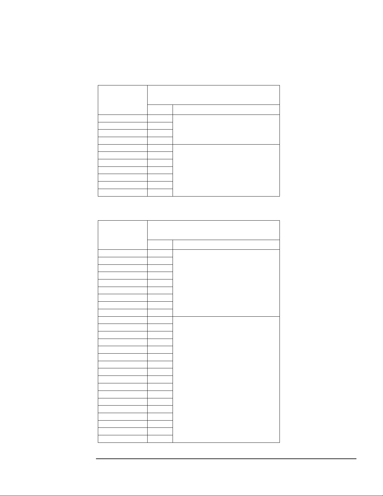
Fuse Specifications
Table 1a through 1d list the specifications for the LC filter power circuit fuses in the HG7. Refer also
to the drawings and other information shipped with the unit.
Table 1a – Fuse Specifications for HG7 240 Volt Models
HG7
Rating
(kVar)
3 15
3 15
5 25
6 25
8 35
10 45
15 60
15 60
20 80
25 100
30 125
Amps Type
Power Circuit
Fuse Ratings
Class CC Bussmann
type KTK-R
or equivalent
Class T
Bussmann
type JJS
or equivalent
Table 1b – Fuse Specifications for HG7 400 Volt Models
HG7
Rating
(kW)
4 5
5 6
7.5 7
9.3 9
11 12
15 15
18.5 25
22 25
30 30
37 35
45 45
55 60
75 80
90 90
110 110
132 150
160 150
200 200
250 250
315 300
355 350
400 400
450 450
500 500
560 600
630 600
Amps Type
Power Circuit
Fuse Ratings
Class CC Bussmann
type KTK-R
or equivalent
Class T
Bussmann
type JJS
or equivalent
INTRODUCTION HG7 I, O, & M Manual
11
INTRODUCTION
Phone: 800.894.0412 - Fax: 888.723.4773 - Web: www.clrwtr.com - Email: info@clrwtr.com
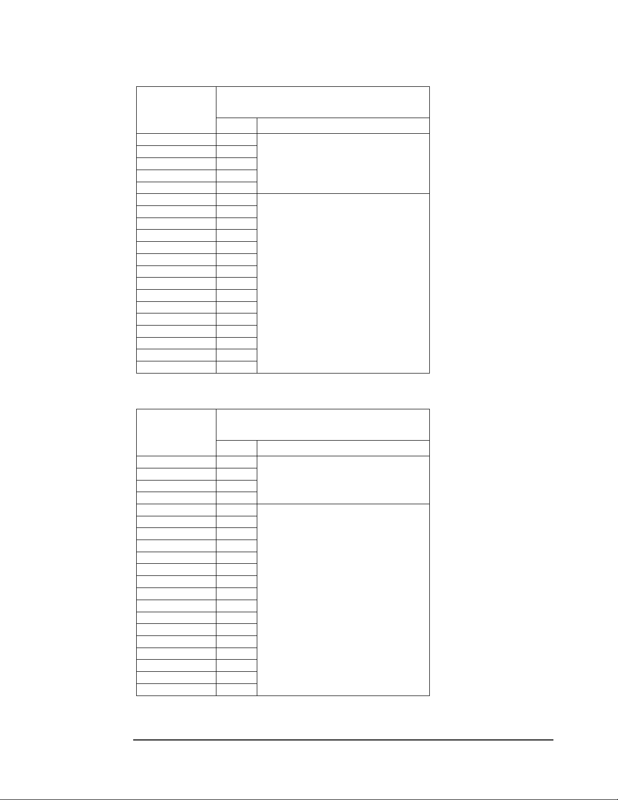
Table 1c – Fuse Specifications for HG7 480 Volt Models
HG7
Rating
(kVar)
3 10
5 15
6 15
10 30
15 30
20 40
25 50
30 60
40 80
45 100
60 125
75 175
90 200
105 225
120 250
150 300
180 400
210 450
240 500
270 600
Amps Type
Power Circuit
Fuse Ratings
Class CC Bussmann
type KTK-R
or equivalent
Class T
Bussmann
type JJS
or equivalent
Table 1d – Fuse Specifications for HG7 600 Volt Models
HG7
Rating
(kVar)
5 10
10 25
15 30
15 30
20 35
25 40
30 50
40 70
45 80
60 100
75 125
90 150
105 175
120 200
150 250
150 250
180 300
210 350
240 400
270 450
Amps Type
Power Circuit
Fuse Ratings
Class CC Bussmann
type KTK-R
or equivalent
Class T
Bussmann
type JJS
or equivalent
INTRODUCTION HG7 I, O, & M Manual
12

INTRODUCTION
Phone: 800.894.0412 - Fax: 888.723.4773 - Web: www.clrwtr.com - Email: info@clrwtr.com
Replacement Parts
If replacement parts are needed, please contact your TCI representative. To ensure that the HG7
harmonic filter continues to perform to its original specifications, replacement parts should conform to
TCI specifications.
Factory Contacts and Tech Support
For technical support, contact your local TCI distributor or sales representative.
You can contact TCI directly at 800-TCI-8282. Select "Customer Service" or "Tech Support" and have
your HG7 harmonic filter nameplate information available.
INTRODUCTION HG7 I, O, & M Manual
13
INTRODUCTION
Phone: 800.894.0412 - Fax: 888.723.4773 - Web: www.clrwtr.com - Email: info@clrwtr.com
Product Description
HG7 Drive-Applied Harmonic Filter
The HG7 is a drive-applied harmonic filter designed and developed by TCI to reduce the harmonic
currents drawn from the power source by variable speed drives. The HG7 is available for 240, 480, 600
(60 Hz) and 400 (50 Hz) volt systems. It is suitable for use with 3-phase diode bridge rectifier loads
such as PWM AC drives.
The HG7 is a passive filter connected in series with the input terminals of a variable speed drive or
several drives that operate as a group. It is designed to provide a low impedance path for the major
harmonic currents demanded by the drive. The filter is a stand-alone device that can be furnished in its
own enclosure and mounted adjacent to the drive. It is also available on an open panel for mounting
within an enclosure with the drive or other equipment.
The HG7 filters consist minimally of the following features and components:
♦ A KDR input series reactor to prevent system interaction and improve filter
performance.
♦ An L-C harmonic filter circuit with:
A TCI 3-phase tuning reactor specifically designed for the HG7 filter
High-endurance, harmonic-rated capacitors
♦ Bleeder resistors to ensure safe capacitor discharge upon filter shutdown.
♦ Cooling fans (on select models) to ensure adequate cooling and safe operating
temperatures.
♦ Compression terminals for ease and integrity of all power and control wiring.
♦ Fuses to protect caps from over-current
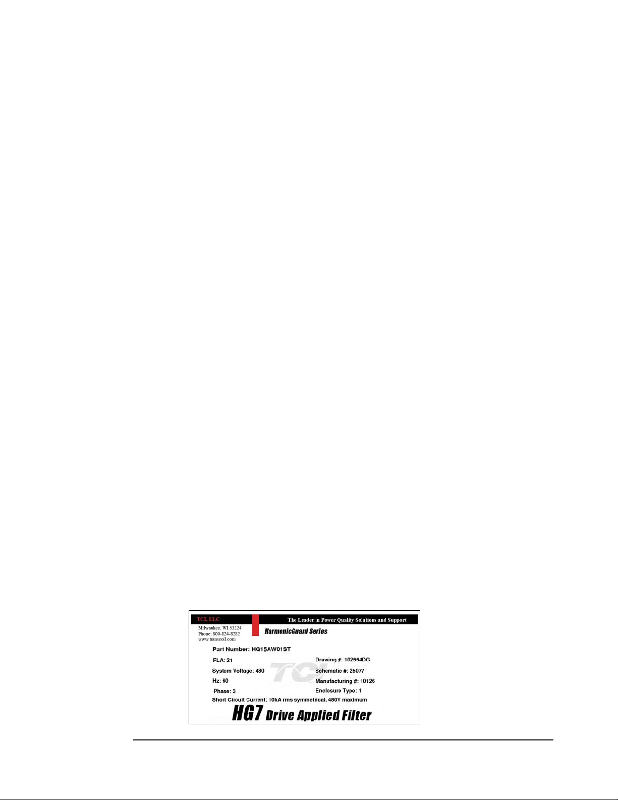
Nameplate Data
Figure 1 shows a typical HG7 harmonic filter nameplate. The following information is marked on the
nameplate:
♦ Part number: encoding is explained on the following page
♦ FLA: the rated continuous operating current (RMS amps)
♦ System Voltage: the rated 3-phase line voltage (RMS volts)
♦ Hz: the rated frequency (60 Hz/50 Hz)
♦ Phase: 3 – The HG7 filter is designed for use only with 3-phase power.
♦ Drawing #: outline and mounting dimension drawing number
♦ Schematic #: schematic diagram drawing number
♦ Manufacturing #: for TCI internal use
♦ Enclosure Type: UL designation or "Open" panel construction
Figure 1 – Typical HG7 Harmonic Filter Nameplate
INTRODUCTION HG7 I, O, & M Manual
14
 Loading...