

Panasonic PT-DZ8700E, PT-DW8300E User Manual
Operating Instructions
Functional Manual
DLP™ Based Projector
Model No.
PT-DZ8700U
PT-DS8500U
PT-DW8300U
Commercial Use
The projection lens is sold separately.
Thank you for purchasing a Panasonic Projector.
J
Before operating this product, please read the instructions carefully and save this manual
for future use.
J
Before using your projector, be sure to read “
pages 8 to 16).
(
Æ
Precautions with regard to safety”
TQBJ0341
ENGLISH
Important Safety Notice
2
- ENGLISH
Important
Information
Important Safety Notice
Dear Panasonic Customer:
The following information should be read and understood as it provides details, which will enable you to operate
the projector in a manner which is both safe to you and your environment, and conforms to legal requirements
regarding the use of projectors. Before connecting, operating or adjusting this projector, please read these
instructions completely and save this booklet with the projector for future reference. We hope it will help you to
get the most out of your new product, and that you will be pleased with your Panasonic DLP™ Based projector.
The serial number of your product may be found on its bottom. You should note it in the space provided below
and retain this booklet in case service is required.
Model number: PT-DZ8700U/PT-DS8500U/PT-DW8300U
Serial number:
WARNING: TO REDUCE THE RISK OF FIRE OR ELECTRIC SHOCK, DONOT EXPOSE THIS PRODUCT
Power Supply: This Projector is designed to operate on 120 V, 60 Hz AC, house current only.
CAUTION: The AC power cord which is supplied with the projector as an accessory can only be used for
TO RAIN OR MOISTURE.
power supplies up to 125 V, 7 A. If you need to use higher voltages or currents than this, you will
need to obtain a separate 250 V power cord. If you use the accessory cord in such situations, re
may result.
The lightning ash with arrowhead symbol, within an equilateral triangle, is intended to alert the
user to the presence of uninsulated “dangerous voltage” within the product’s enclosure that may
be of sufcient magnitude to constitute a risk of electric shock to persons.
The exclamation point within an equilateral triangle is intended to alert the user to the presence of
important operating and maintenance (servicing) instructions in the literature accompanying the
product.
CAUTION: This equipment is equipped with a three-pin grounding-type power
plug. Do not remove the grounding pin on the power plug. This plug
will only t a grounding-type power outlet. This is a safety feature. If
you are unable to insert the plug into the outlet, contact an electrician.
Do not defeat the purpose of the grounding plug.
Pursuant to at the directive 2004/108/EC, article 9 (2)
Panasonic Testing Center
Panasonic Service Europe, a division of Panasonic Marketing Europe GmbH
Winsbergring 15, 22525 Hamburg, F.R. Germany
NOTICE:
This product has a High Intensity Discharge (HID) lamp that contains mercury. Dispose may be regulated in •
your community due to environmental considerations. For disposal or recycling information, please contact
your local authorities, or the Electronic Industries Alliance: http://www.eiae.org
Do not remove
Important Safety Notice
ENGLISH -
3
Important
Information
WARNING:
This equipment has been tested and found to comply with the limits for a Class B digital device, pursuant
to Part 15 of the FCC Rules. These limits are designed to provide reasonable protection against harmful
interference in a residential installation. This equipment generates, uses and can radiate radio frequency
energy and, if not installed and used in accordance with the instructions, may cause harmful interference to
radio communications. However, there is no guarantee that interference will not occur in a particular installation.
If this equipment does cause harmful interference to radio or television reception, which can be determined by
turning the equipment off and on, the user is encouraged to try to correct the interference by one or more of the
following measures:
Reorient or relocate the receiving antenna. •
Increase the separation between the equipment and receiver. •
Connect the equipment into an outlet on a circuit different from that to which the receiver is connected. •
Consult the dealer or an experienced radio/TV technician for help. •
FCC CAUTION: To assure continued compliance, follow the attached installation instructions and use only
shielded interface cables when connecting to computer and/or peripheral devices. Any
changes or modications not expressly approved by Panasonic Corp. of North America could
void the user’s authority to operate this device.
WARNING:
Not for use in a computer room as dened in the Standard for the Protection of Electronic Computer/Data •
Processing Equipment, ANSI/NFPA 75.
For permanently connected equipment, a readily accessible disconnect device shall be incorporated in the •
building installation wiring.
For pluggable equipment, the socket-outlet shall be installed near the equipment and shall be easily •
accessible.
Declaration of Conformity
Model Number: PT-DZ8700U/PT-DS8500U/PT-DW8300U
Trade Name: Panasonic
Responsible party: Panasonic Solutions Company
Address: 3 Panasonic Way, Secaucus, NJ 07094
Telephone number: (877) 803 - 8492
E-mail: projectorsupport@us.panasonic.com
This device complies with Part 15 of the FCC Rules. Operation is subject to the following two conditions: (1)
This device may not cause harmful interference, and (2) this device must accept any interference received,
including interference that may cause undesired operation.
Information on Disposal in other Countries outside the European
These symbols are only valid in the European Union.
If you wish to discard this product, please contact your local authorities or dealer and ask for the
correct method of disposal.
Environment care information for users in China
This symbol is only valid in China.

4
- ENGLISH
Important
Information
Preparation Getting Started Basic Operation Settings Maintenance Appendix
The size is almost the same as the
former model but the luminance is
about 1.5 times higher.
Heightened luminance
7 000 lm : PT-D7700U
(two lamps LAMP POWER : [HIGH])
J
Quick steps
For details, see the corresponding pages.
1. Set up your projector.
page 21)
(
Æ
10 600 lm : PT-DZ8700U
(two lamps LAMP POWER : [HIGH])
Lengthened lamp
replacement cycle
The lamp replacement cycle is longer
than the existing model. (
Approx. 1 500 hours : PT-D7700U
(two lamps LAMP POWER : [HIGH])
Approx. 3 000 hours : PT-DZ8700U
(two lamps LAMP POWER : [HIGH])
page 110)
Æ
Reduced standby power
The standby power is much less than
the existing model.
2. Attach the projection lens.
page 37)
(
Æ
3. Connect with other devices.
page 34)
(
Æ
4. Connect the power cord.
page 38)
(
Æ
5. Start projecting.
page 39)
(
Æ
Approx. 12 W : PT-D7700U
Approx. 0.2 W : PT-DZ8700U
(STANDBY MODE : [ECO])
6. Select the input signal.
page 41)
(
Æ
7. Adjust the image.
page 41)
(
Æ

ENGLISH -
5
Important
Information
PreparationGetting StartedBasic OperationSettingsMaintenanceAppendix
Contents
Be sure to read “Precautions with regard to safety”. ( pages 8 to 16)
Important Information
Important Safety Notice ............................ 2
Precautions with regard to safety ............ 8
WARNING ..............................................................8
CAUTION .............................................................11
Cautions when transporting ................................. 11
Cautions when installing ......................................12
Security ................................................................14
Cautions on use ...................................................14
Cleaning and maintenance ..................................15
Disposal ...............................................................15
Accessories ..........................................................16
Preparation
About Your Projector .............................. 17
Remote control .....................................................17
Projector body ......................................................18
Setting projector ID number to remote control .....20
Using a wired remote control ...............................20
Making adjustment and selection.........................39
Powering off the projector ....................................40
Direct power off function ......................................40
Projecting ................................................. 41
Selecting the input signal .....................................41
How to adjust the focus, zoom and shift ..............41
Adjustment range after lens position
(optical shift) ..................................................42
Moving the projection lens position to the home
position ..........................................................43
Lens adjustment to compensate for uneven
screen focus ..................................................43
Basic operations using the remote
control................................................... 46
Using the SHUTTER function ..............................46
On-screen display function ..................................46
Switching the input signal ....................................46
STATUS function ..................................................46
Automatic adjustment ..........................................47
Using the FUNCTION button ...............................47
Displaying the internal test pattern.......................47
Changing the picture aspect ratio ........................48
Getting Started
Setting up ................................................. 21
Projection method ................................................21
Screen size and throw distance ...........................22
Front leg adjusters and throwing angle ................33
Connections ............................................. 34
Before connection to the projector .......................34
Connecting example : AV equipment ...................35
Connecting example : Computers........................36
Removing/attaching the projection lens
(optional)
How to install the projection lens .........................37
How to remove the projection lens.......................37
........................................................ 37
Basic Operation
Powering ON/OFF .................................... 38
Connecting the power cord ..................................38
Powering up the projector ....................................39
Settings
Menu Navigation ...................................... 49
Navigating through the menu ...............................49
MAIN MENU ........................................................50
SUB MENU ..........................................................50
PICTURE menu ........................................ 52
PICTURE MODE .................................................52
CONTRAST .........................................................53
BRIGHTNESS ......................................................53
COLOR ................................................................53
TINT .....................................................................53
COLOR TEMPERATURE ....................................54
GAMMA ................................................................55
SYSTEM DAYLIGHT VIEW .................................55
SHARPNESS .......................................................56
NOISE REDUCTION ...........................................56
DYNAMIC IRIS ....................................................56
SYSTEM SELECTOR ..........................................57

6
- ENGLISH
Important
Information
Preparation Getting Started Basic Operation Settings Maintenance Appendix
Contents
POSITION menu ....................................... 58
ADVANCED MENU ................................... 63
To display pictures complying with the sRGB
standard ........................................................57
SHIFT ...................................................................58
ASPECT ...............................................................58
ZOOM ..................................................................59
CLOCK PHASE ...................................................60
GEOMETRY (PT-DZ8700/PT-DS8500 only) .......60
KEYSTONE (PT-DW8300 only) ...........................62
DIGITAL CINEMA REALITY .................................63
BLANKING ...........................................................63
INPUT RESOLUTION ..........................................64
CLAMP POSITION ..............................................64
EDGE BLENDING ...............................................64
FRAME DELAY ....................................................66
RASTER POSITION ............................................66
LAMP SELECT ....................................................76
LAMP RELAY .......................................................76
LAMP POWER .....................................................77
BRIGHTNESS CONTROL ...................................77
STANDBY MODE ................................................81
SCHEDULE .........................................................81
RS-232C ..............................................................82
STATUS ...............................................................83
NO SIGNAL SHUT-OFF ......................................84
REMOTE2 MODE ................................................84
FUNCTION BUTTON ...........................................84
DATE AND TIME ..................................................84
LENS CALIBRATION ...........................................85
FILTER COUNTER RESET .................................85
SAVE ALL USER DATA ........................................86
LOAD ALL USER DATA .......................................86
INITIALIZE ...........................................................86
DISPLAY LANGUAGE menu ................... 67
Changing the display language............................67
DISPLAY OPTION menu .......................... 68
COLOR MATCHING ............................................68
LARGE SCREEN CORRECTION ........................69
SCREEN SETTING
(PT-DZ8700/PT-DS8500 only) ......................69
WAVEFORM MONITOR (PT-DZ8700 only) .........70
AUTO SIGNAL .....................................................71
AUTO SETUP ......................................................71
RGB IN (Only RGB input) ....................................72
DVI-D IN ...............................................................72
HDMI IN ...............................................................73
SDI IN (PT-DZ8700/PT-DS8500 only) .................73
ON-SCREEN DISPLAY .......................................73
BACK COLOR .....................................................74
STARTUP LOGO .................................................74
FREEZE ...............................................................74
PROJECTOR SETUP menu ..................... 75
PROJECTOR ID ..................................................75
INSTALLATION ....................................................75
HIGH ALTITUDE MODE ......................................75
COOLING CONDITION .......................................76
SERVICE PASSWORD .......................................86
P IN P menu .............................................. 87
Using the P IN P function .....................................87
Setting the P IN P function ...................................87
TEST PATTERN menu ............................. 88
TEST PATTERN ...................................................88
SIGNAL LIST menu .................................. 89
Registering a signal to the list ..............................89
Renaming a registered data.................................89
Deleting a registered data ....................................89
Managing the sub memory list .............................90
SECURITY menu ...................................... 91
SECURITY PASSWORD .....................................91
SECURITY PASSWORD CHANGE .....................91
DISPLAY SETTING .............................................92
TEXT CHANGE ...................................................92
MENU LOCK ........................................................92
MENU LOCK PASSWORD ..................................92
CONTROL DEVICE SETUP ................................93
NETWORK menu ..................................... 94
NETWORK SETUP ..............................................94
NETWORK CONTROL ........................................94
NETWORK STATUS ............................................94

ENGLISH -
7
Important
Information
PreparationGetting StartedBasic OperationSettingsMaintenanceAppendix
Network connections............................................95
Accessing from the Web browser ........................96
Contents
Maintenance
Monitor Lamp indicators ....................... 107
Managing the indicated problems ......................107
Replacement .......................................... 109
Before replacing the unit ....................................109
Replacing the unit ..............................................109
Troubleshooting .....................................112
Appendix
Technical Information ............................114
PJLink protocol ..................................................114
Control commands via LAN ............................... 115
Serial terminal ....................................................117
REMOTE 2 IN terminal ......................................120
Two window display combination list .................121
Restoring the MENU LOCK PASSWORD
to default......................................................121
List of compatible signals ...................................122
Specications ........................................ 124
Dimensions ........................................................126
About brand .......................................................126
Ceiling mount bracket safeguards....... 127
Attachment procedure........................................127
Index ....................................................... 128

8
- ENGLISH
Important
Information
Precautions with regard to safety
WARNING
The wall outlet or the circuit breaker shall be installed near the equipment and shall be
easily accessible when problems occur. If the following problems occur, cut off the power
supply immediately.
Continued use of the projector in these conditions will result in re or electric shock.
z
z
z
Please contact an Authorized Service Center for repairs, and do not attempt to repair the projector yourself.
During a thunderstorm, do not touch the projector or the cable.
Electric shocks can result.
Do not do anything that might damage the power cord or the power plug.
If the power cord is used while damaged, electric shocks, short-circuits or re will result.
z
Ask an Authorized Service Center to carry out any repairs to the power cord that might be necessary.
Insert the power plug securely into the wall outlet.
If the plug is not inserted correctly, electric shocks or overheating will result.
z
z
z
Clean the power plug regularly to prevent it from becoming covered in dust.
Failure to observe this will cause a re.
z
z
Pull the power plug out from the wall outlet and wipe it with a dry cloth regularly.
Do not handle the power plug with wet hands.
Failure to observe this will result in electric shocks.
Do not overload the wall outlet.
If the power supply is overloaded (ex., by using too many adapters), overheating may occur and re will result.
POWER
If foreign objects or water get inside the projector, cut off the power supply.
If the projector is dropped or the cabinet is broken, cut off the power supply.
If you notice smoke, strange smells or noise coming from the projector, cut off the power supply.
Do not damage the power cord, make any modications to it, place it near any hot objects, bend it
excessively, twist it, pull it, place heavy objects on top of it or wrap it into a bundle.
Do not use anything other than the provided power cord.
Do not use the provided power cord for other electrical equipment.
Do not use plugs which are damaged or wall outlets which are coming loose from the wall.
If dust builds up on the power plug, the resulting humidity can damage the insulation.
If not using the projector for an extended period of time, pull the power plug out from the wall outlet.
ON USE/INSTALLATION
Do not place liquid containers on top of the projector.
If water spills onto the projector or gets inside it, re or electric shocks will result.
If any water gets inside the projector, contact an Authorized Service Center.
Do not place the projector on soft materials such as carpets or sponge mats.
Doing so will cause the projector to overheat, which can cause burns, re or damage to the projector.
Do not set up the projector in humid or dusty places or in places where the projector may
come into contact with oily smoke or steam, ex. a bathroom.
Using the projector under such conditions will result in re, electric shocks or components deterioration.
Components deterioration (such as ceiling mount brackets) may cause the projector which is mounted on the
ceiling to fall down.
Do not install this projector in a place which is not strong enough to take the full weight of
the projector or on top of a surface which is sloped or unstable.
Failure to observe this will cause projector to fall down or tip over the projector, and severe injury or damage
could result.

Precautions with regard to safety
ENGLISH -
9
Important
Information
Do not place another projector or other heavy objects on top of the projector.
Failure to observe this will cause the projector to become unbalanced and fall, which could result in damage or
injury. The projector will be damaged or deformed.
Installation work (such as ceiling suspension) should only be carried out by a qualied
technician.
If installation is not carried out and secured correctly it can cause injury or accidents, such as electric shocks.
Do not use anything other than an authorized ceiling mount bracket.
z
Be sure to use the provided accessory wire with an eye bolt as an extra safety measure to prevent the
z
projector from falling down. (Install in a different location to the ceiling mount bracket)
Do not cover the air inlet port or the air outlet port.
Doing so will cause the projector to overheat, which can cause re or damage to the projector.
Do not place the projector in narrow, badly ventilated places such as closets or bookshelves.
z
Do not place the projector on cloth or papers, as these materials could be drawn into the air inlet port.
z
Do not place your hands or other objects close to the air outlet port.
Doing so will cause burns or damage your hands or other objects.
Heated air comes out of the air outlet port. Do not place your hands or face, or objects which cannot withstand
z
heat close to this port.
Do not look and place your skin into the lights emitted from the lens while the projector is
being used.
Doing so can cause burns or loss of sight.
Strong light is emitted from the projector’s lens. Do not look or place your hands directly into this light.
z
Be especially careful not to let young children look into the lens. In addition, turn off the power and disconnect
z
the power plug when you are away from the projector.
Do not insert any foreign objects into the projector.
Doing so will cause re or electric shocks.
Do not insert any metal objects or ammable objects into the projector or drop them onto the projector.
z
Never attempt to remodel or disassemble the projector.
High voltages can cause re or electric shocks.
For any inspection, adjustment and repair work, please contact an Authorized Service Center.
z
Do not project an image with the lens cover attached.
Doing so can cause re.
When replacing the lamp, do not touch the fan with your nger or another part of your
body.
If you do so, you may get hurt.
ACCESSORIES
Do not use or handle the batteries improperly, and refer to the following.
Failure to observe this will cause burns, batteries to leak, overheat, explode or catch re.
Do not use unspecied batteries.
z
Use manganese batteries but not rechargeable batteries.
z
Do not disassemble dry cell batteries.
z
Do not heat the batteries or place them into water or re.
z
Do not allow the + and
z
necklaces or hairpins.
Do not store batteries together with metallic objects.
z
Store the batteries in a plastic bag and keep them away from metallic objects.
z
Make sure the polarities (+ and
z
Do not use a new battery together with an old battery or mix different types of batteries.
z
Do not use batteries with the outer cover peeling away or removed.
z
Remove the empty batteries from the remote control at once.
z
Insulate the battery using tape or something similar before disposal.
z
-
terminals of the batteries to come into contact with metallic objects such as
-
) are correct when inserting the batteries.

Precautions with regard to safety
10
- ENGLISH
Important
Information
Do not allow children to reach the AA/R6 batteries.
z
z
If the battery uid leaks, do not touch it with bare hands, and take the following measures if
necessary.
z
z
Do not disassemble the lamp unit.
If the lamp breaks, it could cause injury.
Lamp replacement
The lamp has high internal pressure. If improperly handled, an explosion and severe injury or accidents will result.
z
z
z
z
Do not allow infants or pets to touch the remote control unit.
z
Keep the attached screws and plain washers away from babies and infants.
z
z
The battery can cause personal injury if swallowed.
If swallowed, seek medical advice immediately.
Battery uid on your skin or clothing could result in skin inammation or injury.
Rinse with clean water and seek medical advice immediately.
Battery uid coming in contact with your eyes could result in loss of sight.
In this case, do not rub your eyes. Rinse with clean water and seek medical advice immediately.
Replacement of the lamp should be carried out by a qualied technician.
The lamp can easily explode if struck against hard objects or dropped.
Before replacing the lamp, be sure to disconnect the power plug from the wall outlet.
Electric shocks or explosions can result if this is not done.
When replacing the lamp, allow it to cool for at least one hour before handling it otherwise it can cause burns.
Keep the remote control unit out of the reach of infants and pets after using it.
If a baby swallows a screw by accident, it may be affected badly.
If a baby seems to have swallowed a screw, consult the doctor immediately.

Precautions with regard to safety
ENGLISH -
11
Important
Information
CAUTION
POWER
When disconnecting the power cord, be sure to hold the power plug and power connector.
If the power cord itself is pulled, the lead will become damaged, and re, short-circuits or serious electric shocks
will result.
When not using the projector for an extended period of time, disconnect the power plug
from the wall outlet and remove the batteries from the remote control.
Disconnect the power plug from the wall outlet before carrying out any cleaning.
Electric shocks can result if this is not done.
ON USE/INSTALLATION
Do not put your weight on this projector.
You could fall or the projector could break, and injury will result.
Be especially careful not to let young children stand or sit on the projector.
z
Do not place the projector in extremely hot locations.
Doing so will cause the outer casing or internal components to deteriorate, or result in re.
Take particular care in locations exposed to direct sunlight or near stoves.
z
Always disconnect all cables before moving the projector.
Moving the projector with cables still attached can damage the cables, which will cause re or electric shocks to
occur.
Do not place your hands in the openings beside the optical lens, while shifting the lens.
Failure to observe this could cause injury.
ACCESSORIES
Do not use the old lamp unit.
If used it could cause lamp explosion.
If the lamp has broken, ventilate the room immediately. Do not touch or bring your face
close to the broken pieces.
Failure to observe this will cause the user to absorb the gas which was released when the lamp broke and which
contains nearly the same amount of mercury as uorescent lamps, and the broken pieces will cause injury.
If you believe that you have absorbed the gas or that the gas has got into your eyes or mouth, seek medical
z
advice immediately.
Ask your dealer about replacing the lamp unit and check the inside of the projector.
z
Cautions when transporting
When transporting the projector or carrying it around, make sure that the lens cover is always in place, and
remove the lens. Please take care to keep them away from vibration and impacts, both the projector and the lens
are precision-made and easily susceptible to damage.
When transporting the projector, the leg adjusters must be housed and do not hold them. Please securely hold
only its bottom and none of its other parts or surfaces as this will result in malfunctions.

Precautions with regard to safety
12
- ENGLISH
Important
Information
Cautions when installing
z
z
z
z
z
z
After removing the projection lens, install the dust sponge attached to the
projector.
If the dust sponge is not installed, dust will be accumulated inside and can cause a trouble.
Do not use under the following conditions.
Do not set up the projector outdoors.
The projector is designed for indoor use only.
Avoid setting up in places which are subject to vibration or shocks.
If the projector is installed in a place where vibrations are transmitted or mounted in a car or a vessel,
vibrations or impacts will result in damage to the internal parts, causing failure. Install the product in a place
free from vibrations and impacts.
Avoid setting up in places which are subject to sudden temperature changes, such as near an air
conditioner or lighting equipment.
Failure to observe this will result in malfunctions or the lamp life will be shortened.
See “ ■ TEMP indicator” on page 108.
Avoid setting up in places which are near high-voltage power lines or near motors.
The product will be exposed to interference if it is installed in the vicinity of high-voltage electrical power lines
or power sources.
Do not install the projector at elevations higher than 2 700 m (8 858 ft) above sea level.
If using this projector at high elevations 1 400 - 2 700 m (4 593 - 8 858 ft) above sea level, set [HIGH
ALTITUDE MODE] to [ON].
If using this projector at elevations lower than 1 400 m (4 593 ft) above sea level, set [HIGH ALTITUDE
MODE] to [OFF].
Failure to observe this will result in malfunctions or the lamp life or life of other components will be shortened.
When installing and using the projector at an angle that exceeds 30° vertically, set [COOLING
CONDITION].
Failure to observe this will result in malfunctions or the lamp life or other components will be shortened.
Lens Focus
Do not adjust the lens focus in the initial period after switching the projector on. The high clarity projector lens is
thermally affected by the light from the light source, making the focus unstable in the period just after switching
on. Please allow a warm-up time of at least 30 minutes before adjusting the lens focus.
Be sure to ask a specialized technician when installing the product to a
ceiling.
If the product is to be installed hanging from the ceiling, purchase an optional Ceiling Mount Attachment (For high
ceilings: Model No. ET-PKD310H, For low ceilings: Model No. ET-PKD310S). Please call a specialized technician
or contact an Authorized Service Center for installation.
Precautions with regard to safety
ENGLISH -
13
Important
Information
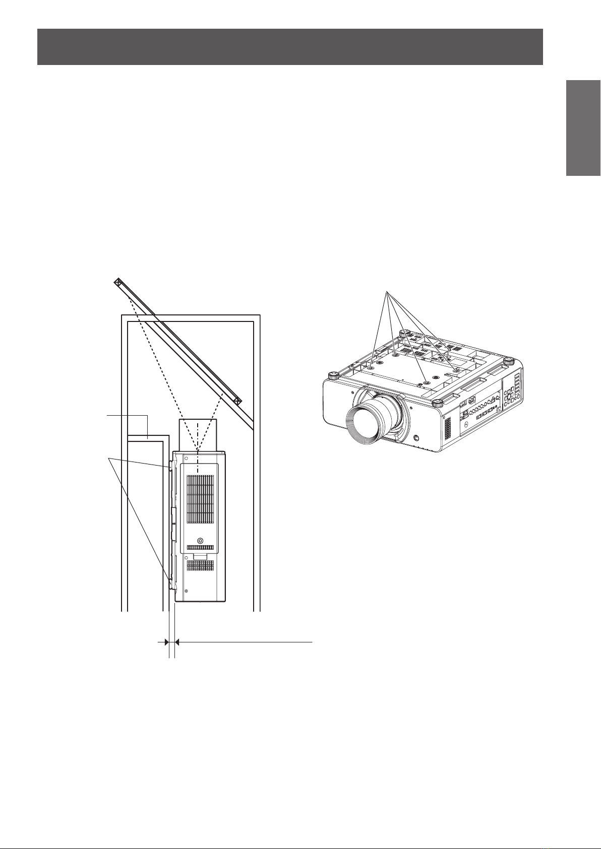
Cautions when setting the projectors 1
When installing and using the projector with a method other than oor standing installing using adjustable
z
feet, x it with the 5 ceiling mounting screws (shown in the gure).
(Screw diameter: M6, Tapping depth inside set: 8 mm)
Make a clearance of at least 5 mm between the projector bottom and setting surface by inserting spacers
z
(metallic) etc. between them.
The adjustable feet can be removed if they are not necessary for installation. However, do not use the screw
z
holes for them to x the projector.
Do not tighten other screws etc. into the screw holes for the adjustable feet.
Doing so can break the set.
When installing the removed adjustable feet again, note that the front and rear ones have different lengths.
(The longer screws are used for front feet. Length of front leg screw: 65 mm, Length of rear leg screw:
23 mm)
When installing the projector with a method other than oor standing installing, do not adjust its angle with the
z
adjustable feet. Doing so can break the set.
Ceiling mounting screws (M6)
Base
Spacers
Gap (Min. 5 mm)
Make sure air can circulate
around the air intake vent.
Failure to do so may result
in the projector not operating
properly.
Precautions with regard to safety
14
- ENGLISH
Important
Information
z
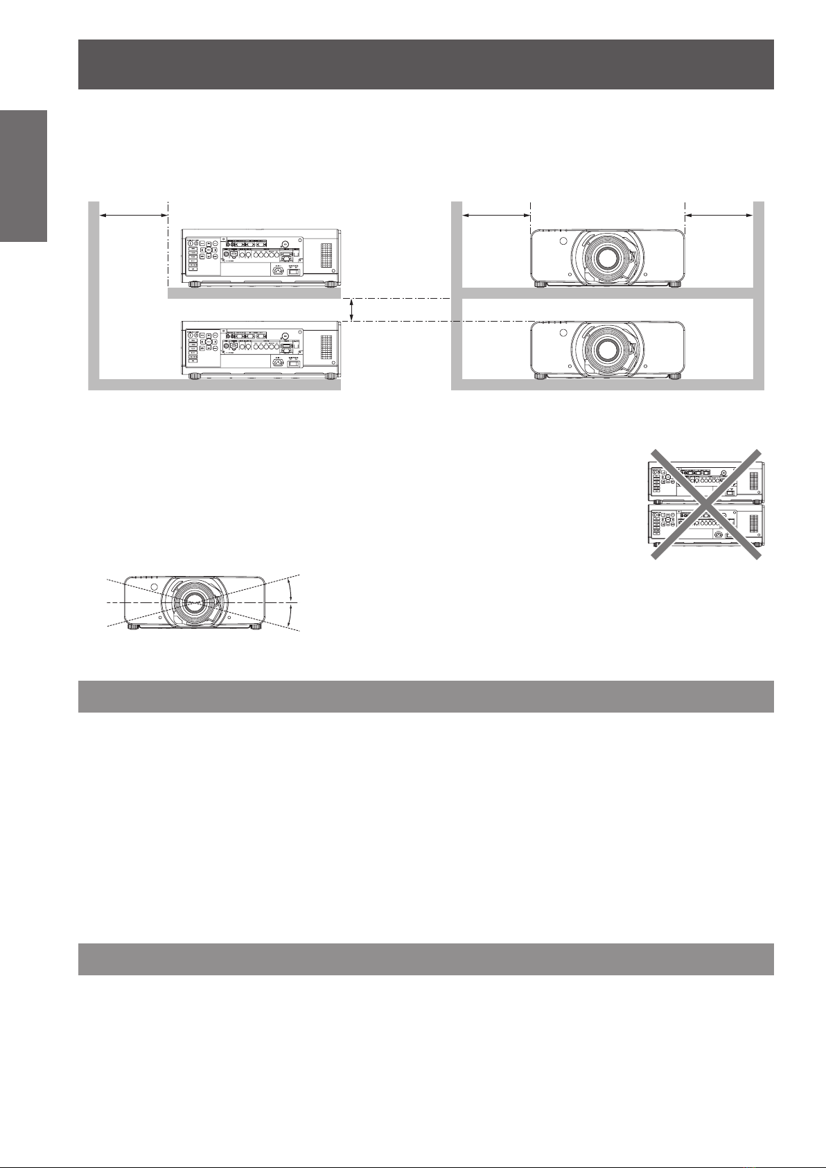
Cautions when setting the projectors 2
When placing the projector in conned space, a ventilation or air conditioning system must be equipped, and
keep enough ventilation space on the rear and both sides of the projector.
over 50 cm (20")
over 10 cm (4")
Make a clearance of at least 5 mm between the projector bottom and setting surface by inserting spacers
z
(metallic) etc. between them.
zDo not stack the projectors without using frame or shelf.
Do not cover the ventilation openings or place anything within 50 cm (20") of them
z
as this may cause damage or injury.
Avoid heating or cooling air of the air conditioning systems directly blow on to the
z
projector ventilation openings.
You can tilt the projector within ± 15 degrees horizontally.
z
+15°
over 50 cm (20") over 50 cm (20")
-
15°
Security
Take safety measures against following incidents.
Personal information being leaked via this product.
z
Unauthorized operation of this product by a malicious third party.
z
Interfering or stopping of this product by a malicious third party.
z
Security instruction
The connecting network must be secured by rewall or others.
z
Change your password regularly.
z
Do not use a password that is simple to guess.
z
Panasonic and its afliate companies would never directly inquire about your password.
z
Do not share your password with the general public.
z
Set a password, and place restrictions on the users who can log in.
z
Cautions on use
In order to get the picture quality
Draw curtains or blinds over windows and turn off any lights near the screen to prevent outside light or light
z
from indoor lamps from shining onto the screen.
Depending on where the projector is used, air exhaust vents or the warm air from air conditioning can cause
z
a shimmering effect on the screen. For this reason, take care not to shield the air exhaust vents and consider
the direction of the air owing from air conditioning.

Precautions with regard to safety
ENGLISH -
15
Important
Information
Do not touch the surface of the projector lens with your bare hand.
If the surface of the lens becomes dirty from ngerprints or anything else, this will be magnied and projected
onto the screen. Please put the lens cover on the projector when you do not use it.
Do not move the projector while it is operating or subject it to vibration or
impact.
The service life of its internal components will be shortened.
The projector has a high pressure mercury lamp that is characterized as
follows:
The brightness of the lamp will decrease over time.
z
The lamp may explode or shorten the lamp life by shocks or chipping damage.
z
In rare cases, it may burst shortly after the rst use.
z
The possibility of its bursting increases when the lamp is used beyond the replacement time.
z
If the lamp bursts, gas inside the lamp is released in the form of smoke.
z
The life of a mercury lamp varies according to the individual difference or conditions of use.
z
In particular, turning the power on and off frequently and/or repeatedly as well as continuous use for 22 hours
z
will greatly affect the life cycle. Provide a lamp for replacement in advance.
Lamp deterioration accelerates when used continuously for 22 hours or more. Lamp deterioration due to
z
continuous use can be reduced by using the “LAMP RELAY” function.
Connection to external device
When connecting the projector to a computer or external device, use the power cord supplied with the
corresponding device and a commercially available shielded interface cable.
Optical components
It may be necessary to replace the optical components such as DLP chips and Polarizing plates in less than 1
year if using the projector in a high temperature environment or in a very dusty, oily smoke or tobacco smoke
environment. For more details, please contact your dealer.
DLP chips
The DLP chips are precision-made. Note that in rare cases, pixels of high precision could be missing or always lit,
but this is not a malfunction. Please take note that directing a laser beam onto the lens surface can damage the
DMD element.
Cleaning and maintenance
Ask an Authorized Service Center to clean the inside of the projector at
least once a year.
If dust is left to build up inside the projector without being cleaned out, it can result in re or problems with
operation. It is a good idea to clean the inside of the projector before the season when humid weather arrives.
Ask your nearest Authorized Service Center to clean the projector when required.
Please discuss with the Authorized Service Center regarding cleaning costs.
Be sure to remove the power plug from the wall outlet before cleaning.
z
Use soft and dry cloth to clean the cabinet.
z
Use a soft cloth moistened in warm water to clean away oil. Do not use solvents such as benzene, thinner,
and alcohol, detergents for kitchens, or a chemical cloth. If using such solvents, the outer case will become
deformed, and the paint may peel off.
Do not clean the lens surface with fuzzy or dusty cloths.
z
If dust adheres to the lens, it will be magnied and projected on the screen. Use a soft and clean cloth to wipe
off dust.
Disposal
When discarding this product, please contact your local authorities or dealer and ask for the correct method of
disposal.
Precautions with regard to safety
Information
Important
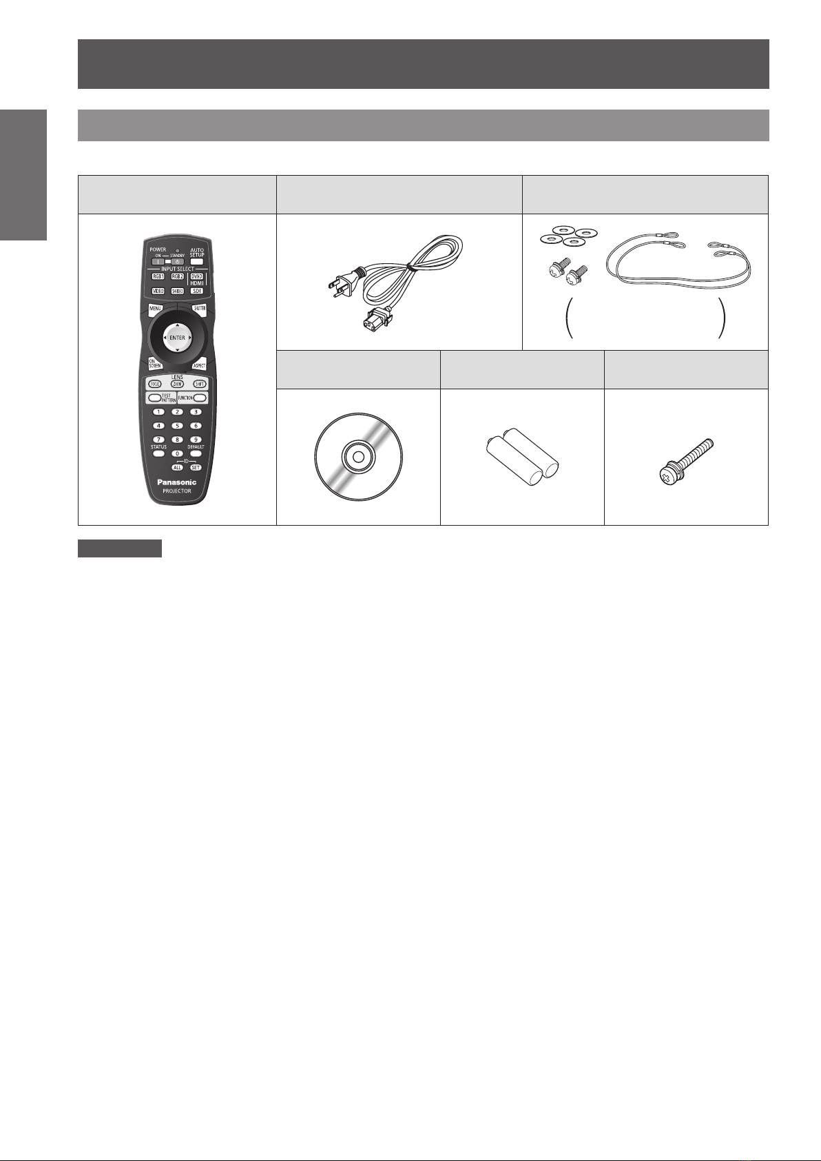
Accessories
Make sure the following accessories are provided with your projector.
Remote control (x1)
(N2QAYB000550)
Power cord (x1)
(TXFSX01RGQZ)
CD-ROM (x1)
(TXFQB02VKN)
Drop-prevention bracket (x2)
(TTRA0238)
AA/R6 batteries for
remote control (x2)
Safety cables (x2)
Washers (x4)
Wire rope xing screw (x2)
Lens xing screw (x1)
(XYN4+J18FJ)
Attention
After unpacking the projector, discard the power cord cap and packaging material properly.
z
For lost accessories, consult your dealer.
z
The part numbers of accessories and separately sold components are subject to change without notice.
z
Store small parts in an appropriate manner, and keep them away from young children.
z
16
- ENGLISH
About Your Projector
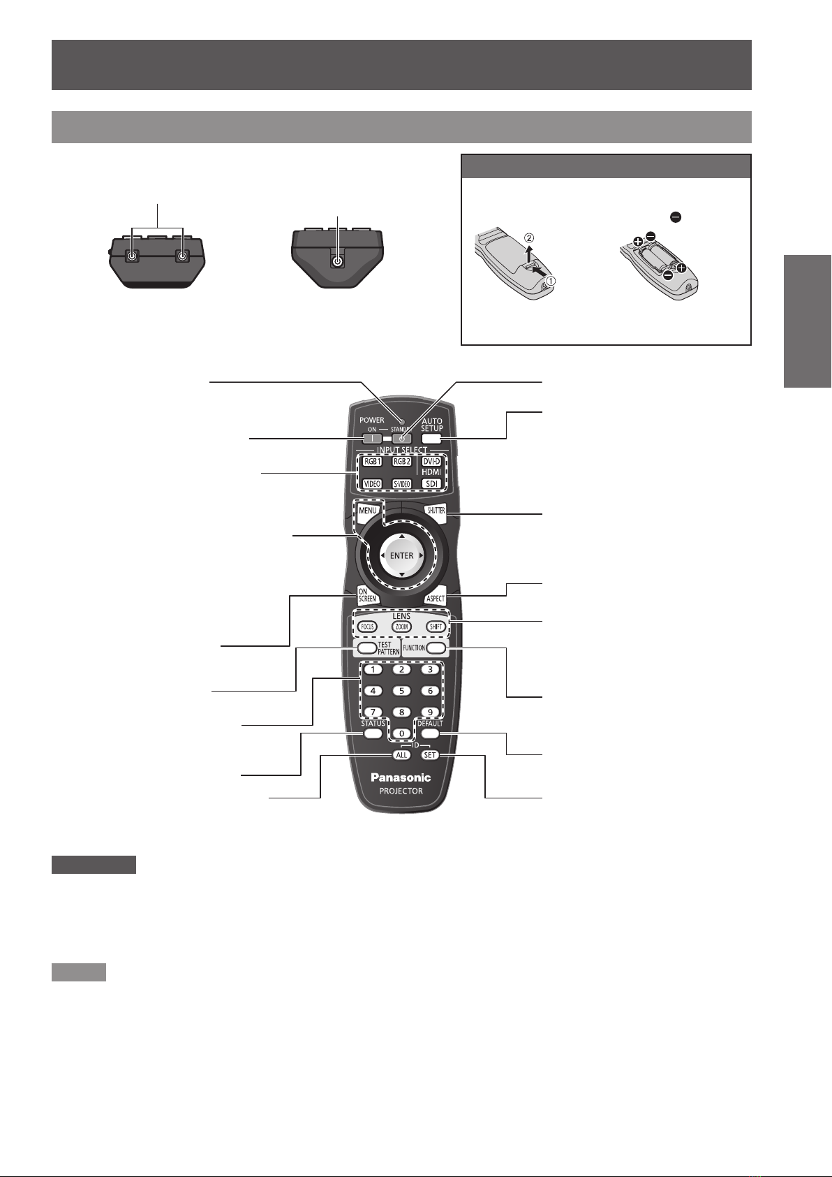
Remote control
J
Top view
Remote control signal emitters
J
Front view
Remote control indicator
Flashes by pressing any
buttons.
Starts the projection while in the
standby mode.
These buttons select the RGB1,
RGB2, DVI-D, VIDEO, S-VIDEO
and SDI terminals. (
<MENU> button
Displays and clears the main menu, and
returns to the previous menu when the
menu is displayed.
Navigation and <ENTER> buttons
Navigate through the menu items with
▲▼◄►, and activate them with the
<ENTER> button. (
Displays and clears the on
screen indications.
(
page 46)
Æ
Displays the test pattern.
(
page 47)
Æ
Enter ID number of the remote
control and adjustment values of
menu items.
Displays projector information.
Makes the remote control available
to control any ID projectors.
(
page 20)
Æ
page 46)
Æ
page 49)
Æ
J
Bottom view
Remote control wired terminal
(
page 20)
Æ
Installing/removing batteries
Press the tab and
lift up the cover.
Returns to the standby mode.
Pressing this button while projecting
an image automatically corrects the
picture positioning on the screen.
While the auto setup feature is active,
a message “PROGRESS” appears on
the screen. (
Pressing this button toggles the
projector’s internal mechanical shutter
to black out the projector.
(
Switches the image aspect ratio.
(
These buttons are used together with
▲▼◄► to adjust focus, zoom and
shift by the projection lens.
(
Assign the frequently use functions
from options for shortcut.
(
Restores the default factory setting.
(
Species the ID of the remote control.
(
Insert the batteries according to
the polarity diagram indicated
inside. (insert the
Remove the batteries in the
reverse order to setting.
page 47)
Æ
page 46)
Æ
page 48)
Æ
pages 39, 41)
Æ
page 47)
Æ
page 49)
Æ
page 20)
Æ
side rst).
Preparation
Attention
Do not drop the remote control.
z
Avoid contact with liquids or moisture.
z
Do not attempt to modify or disassemble the remote control.
z
Do not let strong light shine onto the signal receptor. The remote control may malfunction under strong light such as
z
uorescent.
Note
The remote control can be used within a distance of about 30
z
remote control can control at angles of up to ± 15
be reduced.
If there are any obstacles between the remote control and the remote control signal receptor, the remote control may not
z
operate correctly.
The signal will be reected off the screen. The operating range may differ due to the screen material.
When the projector receives a signal from the remote control, the Power indicator will ash.
z
°C vertically and ± 30 °C horizontally, but the effective control range may
m if pointed directly at the remote control receiver. The
ENGLISH -
17

About Your Projector
Projector body
J
Preparation
Front view
Power indicator (STANDBY(R) / ON(G))
Indicates the power supply status.
Lamp1 indicator (LAMP1)
Indicates the lamp1 unit status. (
Lamp2 indicator (LAMP2)
Indicates the lamp2 unit status. (
Temperature indicator (TEMP)
Indicates the temperature status. (
Filter indicator (FILTER)
Indicates the lter status. (
Remote control
signal receptor
Front leg adjusters
Screw up/down to adjust
the projection angle.
Æ
page 107)
Æ
page 107)
Æ
page 108)
Æ
page 108)
J
Side views
Security lock
CONTROL
PANEL
AC IN terminal
Connect the power cord to supply
electronic power to the projector.
<MAIN POWER> switch
Switch the projector on/off.
Air intake port
Auto Cleaning
Filter (ACF)
compartment
(
page 109)
Æ
Air intake portTerminals on side
Air intake port
J
Rear view
Air exhaust port
Lamp unit compartment
(
page 110)
Æ
Remote control
signal receptor
Air exhaust port
Attention
Keep your hands and other objects away from the air outlet port.
Keep your hand and face away.
z
Keep heat-sensitive articles away.
z
Inserting your nger may result in injury.
z
Heated air from the air outlet port can cause burns or deformations.
J
Bottom view
Burglar hook port
: Attach a commercial burglar prevention cable.
Û
Û
Air intake port
18
- ENGLISH
About Your Projector
ENGLISH -
19
Preparation
J
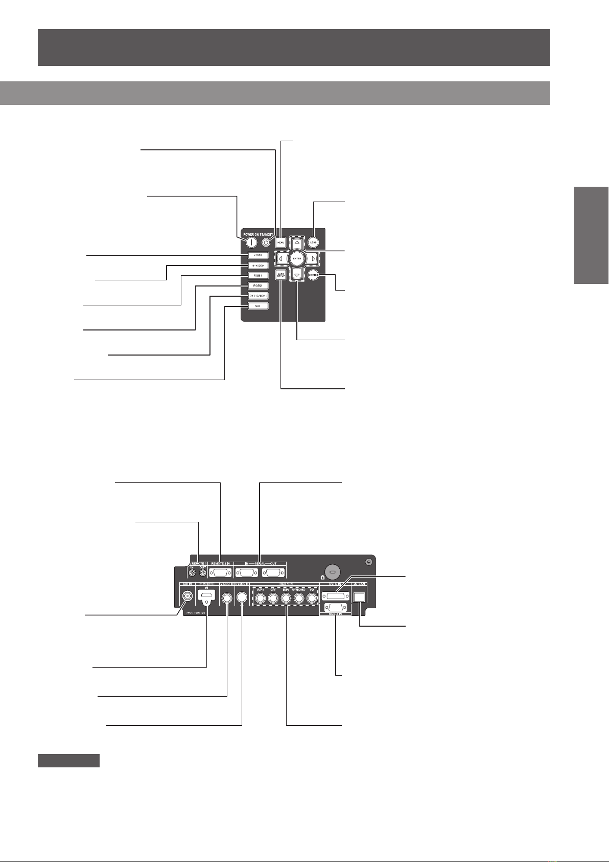
CONTROL PANEL
<STANDBY> button
Returns to the standby mode.
<POWER ON> button
Starts the projection while in the
standby mode.
VIDEO
Switches to VIDEO input.
S-VIDEO
Switches to S-VIDEO input.
RGB1
Switches to RGB1 input.
RGB2
Switches to RGB2 input.
DVI-D/HDMI
Switches to DVI-D or HDMI input.
SDI
Switches to SDI input.
(PT-DZ8700U/PT-DS8500U only)
J
Terminals on side
<MENU> button
Displays and clears the main menu, and returns to the previous
menu when the menu is displayed.
If you hold it down for at least 3 seconds while the on-screen
indication is [OFF], the [OFF] state is canceled. (
<LENS> button
This button is used together with ▲▼◄► to
adjust focus, zoom and shift by the projection
lens.
<ENTER> button
Press to activate a menu selection or to initiate a
function.
<SHUTTER> button
Pressing this button toggles the projector’s
internal mechanical shutter to black out the
projector. (
▲▼◄► button
Use these buttons to select menu items,
change settings, adjust levels, and to enter the
[SECURITY] password.
<AUTO SETUP> button
Pressing this button while projecting an image
automatically corrects the picture positioning on
the screen. While the auto setup feature is active,
a message “PROGRESS” appears on the screen.
(
page 47)
Æ
page 46)
Æ
page 49)
Æ
REMOTE 2 IN
Connect a cable from an
external control circuit.
REMOTE 1 IN/OUT
When two or more main
units are used in the system,
they can be connected and
controlled with wired remote
control cable.
SDI IN
Connect an SDI signals.
(PT-DZ8700U/PT-DS8500U
only)
HDMI IN
Connect a HDMI signals.
VIDEO IN
Connect a VIDEO signals.
S-VIDEO IN
Connect an S-VIDEO signals.
Attention
Do not touch the LAN terminal with your bare hands or body, as body parts may have charged static electricity. Failure to
z
do so may cause malfunctions.
Do not touch the metallic parts of LAN terminal and cable.
Please connect the LAN to indoor devices only.
z
SERIAL IN/OUT
Connect an RS-232C cable from/to a computer.
DVI-D IN
Connect a single link DVI-D
signals.
LAN
Connect a LAN cable for network
connection.
RGB2 IN
Connect an RGB or YP
RGB (YPBPR)1 IN
Connect an RGB or YP
BPR
BPR
signals.
signals.

About Your Projector
Setting projector ID number to remote control
Each projector can be assigned a unique ID number,
and the handheld remote’ s number must be set to
match the intended projector.
The ID number of the projector is set to “ALL” on
shipping, and use the ID ALL button of the remote
Preparation
control when using only a single projector.
Attention
Do not press <ID SET> button accidentally or carelessly
z
because the ID number on the remote control can be set
even when no projector is around.
If you do not enter the 2 digits ID number within 5
z
seconds after <ID SET> button has been pressed, the ID
will remain at the number that was set before <ID SET>
button was pressed.
Your specied ID number is stored in the remote control
z
unit unless another one is specied later. However, the
stored ID will be erased if the batteries of the remote
control are left exhausted. When the batteries are
replaced, set the same ID number again.
The ID number can be set to “ALL” or from “1” to “64”.
z
Press <ID SET> button, and the 1 )
projector (s) will display it’s current ID
number onscreen. Within 5 seconds,
use the numeric keys (0-9) to match
the Remote’s ID number with that of
the desired projector.
Using a wired remote control
When multiple projectors are connected as part of the
system, connect to units with a M3 stereo mini jack
commercial cable to simultaneously control multiple
main units with a single remote control through the
REMOTE 1 IN/OUT terminal. It is effective to use the
wired remote control in the environment in which an
obstacle stands in the light path or where devices are
susceptible to outside light.
Connect to the remote
control wired terminal
Remote Control
M3 stereo mini jack cable
(commercial)
Connect to the
secondary projector
Connection terminals
Note
Refer to “PROJECTOR ID” of “PROJECTOR SETUP
z
menu” (
page 75).
Æ
Attention
Use 2 core shielded cable of length of 15 m or less. If the
z
length of the cable exceeds 15 m (49' 2"), the shielding
of the cable may not be sufcient and the remote control
may not work.
20
- ENGLISH
Setting up
Projection method
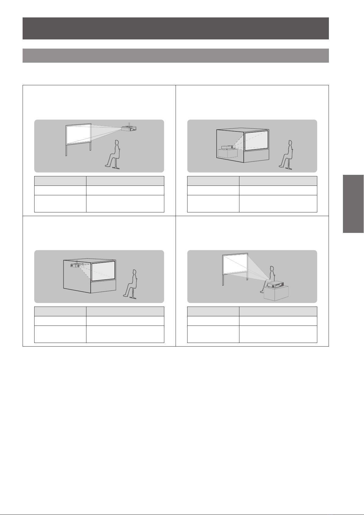
You can use the projector with any of the following 4 projection methods. To set the desired method in the
projector.
J
Mounting on the ceiling and
projecting from front
Û
Menu
INSTALLATION FRONT/CEILING
COOLING
CONDITION
J
Mounting on the ceiling and
Method
CEILING SETTING
projecting from rear
(Using translucent screen)
J
Setting on a desk/oor and
projecting from rear
(Using translucent screen)
Û
Menu
INSTALLATION REAR/FLOOR
COOLING
CONDITION
J
Setting on a desk/oor and
Method
FLOOR SETTING
projecting from front
Getting Started
Û
Menu
INSTALLATION REAR/CEILING
Û
COOLING
CONDITION
Refer to “INSTALLATION” of “PROJECTOR SETUP menu:
details.
CEILING SETTING
Method
Û
Menu
INSTALLATION FRONT/FLOOR
COOLING
CONDITION
” and “COOLING CONDITION” (
Method
FLOOR SETTING
pages 75, 76) for
Æ
ENGLISH -
21

Setting up
22
- ENGLISH
Getting Started
Screen size and throw distance
When planning the projector and screen geometry, refer to the gures below and the information on the following
pages for reference. After the projector is roughly positioned, picture size and vertical picture positioning can be
nely adjusted with the powered zoom lens and lens shifting mechanism.
Projected image
SD
SH
SW
L (LW/LT)
SH Height of the projection area (m)
SW Width of the projection area (m)
H
SD Diagonal length of the projection area (")
Û
LW : Minimum distance:
LT : Maximum distance
Screen
SH
H
SW
Û
Projection distance (m)
L (LW/LT)
L (LW/LT)
Screen
Vertical distance between the lens center level and the
bottom edge of the projected image. (m)
Attention
Before installing, please read
z
Special care should be used when DLP projectors are used in the same room as high power laser equipment.
z
Direct or indirect hitting of a laser beam on to the lens can severely damage the Digital Mirror Devices ™ in which case
there is a loss of warranty.
“Precautions with regard to safety” (Æ pages 8 to 16)

Setting up
ENGLISH -
23
Getting Started
J
Projected range using geometric adjustment
(PT-DZ8700U/PT-DS8500U only)
VERTICAL KEYSTONE (Side View) HORIZONTAL KEYSTONE (Top View)
Screen Screen
VERTICAL ARC (Side View) HORIZONTAL ARC (Top View)
L2
L2
L2 : Projection distance
R2 : Radius of the circle
Screen
R2
L3
Center of
the circle
Screen
L3 : Projection distance
R3
Keystone correction only When using arc and keystone correction together Arc correction only
Lens
ET-D75LE1 ±40 ±15 ±5 ±5 1.6 3.2 0.8 1.6
ET-D75LE2 ±40 ±15 ±5 ±5 1.2 2.4 0.6 1.2
ET-D75LE3 ±40 ±15 ±10 ±10 0.8 1.6 0.4 0.8
ET-D75LE4 ±40 ±15 ±10 ±15 0.6 1.0 0.3 0.5
ET-D75LE5 ±22 ±15 ±5 ±5 3.0 6.0 1.5 3.0
ET-D75LE6 ±28 ±10 ±5 ±5 2.4 4.8 1.2 2.4
ET-D75LE8 ±40 ±15 ±10 ±15 0.4 0.8 0.2 0.4
ET-D75LE10 ±40 ±15 ±5 ±5 1.6 3.2 0.8 1.6
ET-D75LE20 ±40 ±15 ±5 ±5 1.6 3.2 0.8 1.6
ET-D75LE30 ±40 ±15 ±5 ±5 1.2 2.4 0.6 1.2
Vertical
Keystone
Correction
Angle α (°)
R3 : Radius of the circle
Horizontal
Keystone
Correction
Angle β (°)
Vertical
Keystone
Correction
Angle α (°)
Horizontal
Keystone
Correction
Angle β (°)
Screen
Center of
the circle
R2/L2
minimum
value
Screen
R3
R3/L3
minimum
value
L2 : Projection distance
R2 : Radius of the circle
R2
L3
L3 : Projection distance
R3 : Radius of the circle
R2/L2
minimum
value
R3/L3
minimum
value
Note
z
z
When using geometric adjustment, if the amount of compensation is too great, excessive blurring may result.
The curved screens illustrated are simply sections of a full circle.

Setting up
24
- ENGLISH
Getting Started
J
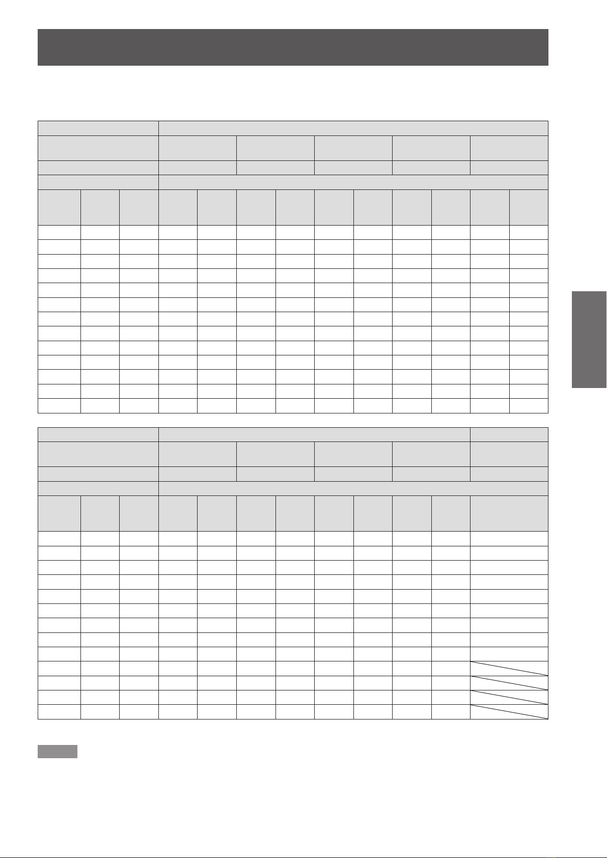
Projection distance by projection lens (for PT-DZ8700U)
Q
For the screen aspect ratio of 16 : 10 (Unit : m)
Model number of
Screen dimensions Projection distance (L)
Screen
size (")
70 0.942 1.508 2.01 2.69 2.72 4.10 4.11 6.90 6.91 11.06 10.78 20.56
80 1.077 1.723 2.31 3.09 3.12 4.70 4.71 7.90 7.91 12.66 12.37 23.55
90 1.212 1.939 2.61 3.49 3.52 5.30 5.31 8.91 8.91 14.25 13.97 26.54
100 1.346 2.154 2.91 3.89 3.92 5.90 5.91 9.91 9.91 15.85 15.57 29.53
120 1.615 2.585 3.51 4.68 4.73 7.10 7.11 11.91 11.92 19.04 18.76 35.50
150 2.019 3.231 4.40 5.88 5.93 8.90 8.91 14.92 14.93 23.82 23.54 44.47
200 2.692 4.308 5.89 7.87 7.93 11.91 11.92 19.94 19.95 31.80 31.52 59.41
250 3.365 5.385 7.39 9.87 9.93 14.91 14.92 24.95 24.96 39.77 39.49 74.36
300 4.039 6.462 8.88 11.86 11.93 17.91 17.92 29.97 29.98 47.75 47.47 89.30
350 4.712 7.539 10.37 13.86 13.93 20.91 20.92 34.98 34.99 55.72 55.44 104.24
400 5.385 8.616 11.86 15.85 15.94 23.92 23.93 40.00 40.01 63.70 63.42 119.19
500 6.731 10.770 14.85 19.84 19.94 29.92 29.93 50.03 50.04 79.65 79.37 149.08
600 8.077 12.923 17.83 23.82 23.94 35.93 35.94 60.06 60.07 95.60 95.32 178.96
Lens type Zoom lens
projection lens
Throw ratio
Effective
height
(SH)
Û
Effective
width
(SW)
ET-D75LE1 ET-D75LE2 ET-D75LE3 ET-D75LE4 ET-D75LE8
1.4–1.8 : 1 1.8–2.8 : 1 2.8–4.6 : 1 4.6–7.4 : 1 7.3–13.8 : 1
Min.
(LW)
Max.
(LT)
Min.
(LW)
Max.
(LT)
Min.
(LW)
Max.
(LT)
Min.
(LW)
Max.
(LT)
Min.
(LW)
Max.
(LT)
Lens type Zoom lens Fixed-focus lens
Model number of
projection lens
(SH)
Û
Effective
width
(SW)
Throw ratio
Screen dimensions Projection distance (L)
Screen
size (")
100 1.346 2.154 1.96 2.34 2.76 3.56 3.55 5.17 5.13 9.99 1.45
120 1.615 2.585 2.36 2.82 3.32 4.30 4.28 6.22 6.18 12.03 1.76
150 2.019 3.231 2.96 3.55 4.18 5.40 5.37 7.81 7.75 15.08 2.22
200 2.692 4.308 3.97 4.75 5.60 7.24 7.19 10.45 10.38 20.16 2.99
250 3.365 5.385 4.98 5.96 7.02 9.07 9.00 13.09 13.00 25.25 3.76
300 4.039 6.462 5.99 7.17 8.44 10.91 10.82 15.73 15.62 30.34 4.53
350 4.712 7.539 6.99 8.37 9.86 12.74 12.64 18.37 18.24 35.42
400 5.385 8.616 8.00 9.58 11.28 14.58 14.46 21.01 20.86 40.51
500 6.731 10.770 10.01 11.99 14.12 18.25 18.09 26.29 26.11 50.68
600 8.077 12.923 12.03 14.40 16.96 21.92 21.73 31.58 31.35 60.85
Effective
height
70 0.942 1.508 1.35 1.62 1.90 2.46 2.46 3.58 3.56 6.94 0.99
80 1.077 1.723 1.55 1.86 2.19 2.83 2.82 4.11 4.08 7.96 1.15
90 1.212 1.939 1.76 2.10 2.47 3.20 3.19 4.64 4.61 8.98 1.30
ET-D75LE6 ET-D75LE10 ET-D75LE20 ET-D75LE30 ET-D75LE5
0.9–1.1 : 1 1.3–1.7 : 1 1.7–2.4 : 1 2.4–4.7 : 1 0.7 : 1
Min.
(LW)
Max.
(LT)
Min.
(LW)
Max.
(LT)
Min.
(LW)
Max.
(LT)
Min.
(LW)
Max.
(LT)
Fixed
Û
The throw ratio is based on the value during projection onto a 150-inch screen size.:
Note
The projection distances listed here involve an error of ±5 %.
z
When geometric adjustment is used, compensation is made so that the screen size becomes smaller than the specied
z
size.

Setting up
ENGLISH -
25
Getting Started
Q
For the screen aspect ratio of 16 : 9 (Unit : m)
Lens type Zoom lens
Model number of
projection lens
(SH)
Û
Effective
width
(SW)
Throw ratio
Screen dimensions Projection distance (L)
Screen
size (")
100 1.245 2.214 2.99 4.00 4.04 6.07 6.08 10.19 10.19 16.29 16.01 30.36
120 1.494 2.657 3.60 4.82 4.86 7.30 7.31 12.25 12.26 19.57 19.29 36.50
150 1.868 3.321 4.53 6.05 6.09 9.15 9.16 15.34 15.35 24.49 24.21 45.72
200 2.491 4.428 6.06 8.10 8.15 12.24 12.25 20.50 20.50 32.69 32.40 61.08
250 3.113 5.535 7.59 10.15 10.21 15.33 15.34 25.65 25.66 40.88 40.60 76.44
300 3.736 6.641 9.13 12.19 12.27 18.41 18.42 30.81 30.81 49.08 48.80 91.79
350 4.358 7.748 10.66 14.24 14.32 21.50 21.51 35.96 35.97 57.28 57.00 107.15
400 4.981 8.855 12.19 16.29 16.38 24.58 24.60 41.12 41.12 65.47 65.19 122.51
500 6.226 11.069 15.26 20.39 20.50 30.76 30.77 51.42 51.43 81.87 81.59 153.23
600 7.472 13.283 18.33 24.49 24.61 36.93 36.94 61.73 61.74 98.26 97.98 183.95
Effective
height
70 0.872 1.550 2.07 2.77 2.80 4.21 4.23 7.09 7.10 11.37 11.09 21.14
80 0.996 1.771 2.38 3.18 3.21 4.83 4.84 8.13 8.13 13.01 12.73 24.21
90 1.121 1.992 2.68 3.59 3.62 5.45 5.46 9.16 9.16 14.65 14.37 27.29
ET-D75LE1 ET-D75LE2 ET-D75LE3 ET-D75LE4 ET-D75LE8
1.4–1.8 : 1 1.8–2.8 : 1 2.8–4.6 : 1 4.6–7.4 : 1 7.3–13.8 : 1
Min.
(LW)
Max.
(LT)
Min.
(LW)
Max.
(LT)
Min.
(LW)
Max.
(LT)
Min.
(LW)
Max.
(LT)
Min.
(LW)
Max.
(LT)
Lens type Zoom lens Fixed-focus lens
Model number of
projection lens
(SH)
Û
Effective
width
(SW)
Throw ratio
Screen dimensions Projection distance (L)
Screen
size (")
100 1.245 2.214 2.01 2.41 2.83 3.67 3.65 5.31 5.28 10.28 1.50
120 1.494 2.657 2.43 2.90 3.42 4.42 4.40 6.40 6.35 12.37 1.81
150 1.868 3.321 3.05 3.65 4.29 5.55 5.52 8.03 7.97 15.50 2.29
200 2.491 4.428 4.08 4.89 5.75 7.44 7.39 10.74 10.67 20.73 3.08
250 3.113 5.535 5.12 6.13 7.21 9.33 9.26 13.46 13.36 25.96 3.87
300 3.736 6.641 6.15 7.37 8.67 11.21 11.13 16.17 16.06 31.18 4.66
350 4.358 7.748 7.19 8.61 10.13 13.10 12.99 18.88 18.75 36.41
400 4.981 8.855 8.22 9.85 11.59 14.99 14.86 21.60 21.45 41.64
500 6.226 11.069 10.29 12.33 14.51 18.76 18.60 27.03 26.84 52.09
600 7.472 13.283 12.36 14.81 17.44 22.54 22.33 32.46 32.23 62.54
Effective
height
70 0.872 1.550 1.39 1.66 1.96 2.53 2.53 3.68 3.66 7.14 1.02
80 0.996 1.771 1.60 1.91 2.25 2.91 2.91 4.23 4.20 8.19 1.18
90 1.121 1.992 1.81 2.16 2.54 3.29 3.28 4.77 4.74 9.23 1.34
ET-D75LE6 ET-D75LE10 ET-D75LE20 ET-D75LE30 ET-D75LE5
0.9–1.1 : 1 1.3–1.7 : 1 1.7–2.4 : 1 2.4–4.7 : 1 0.7 : 1
Min.
(LW)
Max.
(LT)
Min.
(LW)
Max.
(LT)
Min.
(LW)
Max.
(LT)
Min.
(LW)
Max.
(LT)
Fixed
Û
z
z
The throw ratio is based on the value during projection onto a 150-inch screen size.:
Note
The projection distances listed here involve an error of ±5 %.
When geometric adjustment is used, compensation is made so that the screen size becomes smaller than the specied
size.

Setting up
26
- ENGLISH
Getting Started
Q
For the screen aspect ratio of 4 : 3 (Unit : m)
Model number of
Screen dimensions Projection distance (L)
Screen
size (")
70 1.067 1.422 2.29 3.06 3.09 4.65 4.66 7.83 7.83 12.54 12.25 23.32
80 1.219 1.626 2.63 3.51 3.55 5.33 5.34 8.96 8.97 14.34 14.06 26.71
90 1.372 1.829 2.96 3.96 4.00 6.01 6.02 10.10 10.10 16.15 15.87 30.09
100 1.524 2.032 3.30 4.41 4.45 6.69 6.70 11.23 11.24 17.96 17.67 33.47
120 1.829 2.438 3.98 5.32 5.36 8.05 8.06 13.50 13.51 21.57 21.28 40.24
150 2.286 3.048 4.99 6.67 6.72 10.09 10.10 16.91 16.92 26.98 26.70 50.39
200 3.048 4.064 6.68 8.93 8.99 13.49 13.50 22.59 22.59 36.01 35.73 67.31
250 3.810 5.080 8.37 11.18 11.25 16.89 16.90 28.27 28.27 45.04 44.76 84.23
300 4.572 6.096 10.06 13.44 13.52 20.29 20.30 33.94 33.95 54.07 53.79 101.14
350 5.334 7.112 11.75 15.70 15.79 23.69 23.70 39.62 39.63 63.10 62.82 118.06
400 6.096 8.128 13.44 17.96 18.05 27.09 27.10 45.30 45.31 72.13 71.85 134.98
500 7.620 10.160 16.82 22.47 22.58 33.89 33.90 56.65 56.66 90.18 89.91 168.81
600 9.144 12.192 20.20 26.98 27.12 40.69 40.70 68.01 68.02 108.24 107.96 202.65
Lens type Zoom lens
projection lens
Throw ratio
Effective
height
(SH)
Û
Effective
width
(SW)
ET-D75LE1 ET-D75LE2 ET-D75LE3 ET-D75LE4 ET-D75LE8
1.6–2.2 : 1 2.2–3.3 : 1 3.3–5.6 : 1 5.6–8.9 : 1 8.8–16.5 : 1
Min.
(LW)
Max.
(LT)
Min.
(LW)
Max.
(LT)
Min.
(LW)
Max.
(LT)
Min.
(LW)
Max.
(LT)
Min.
(LW)
Max.
(LT)
Lens type Zoom lens Fixed-focus lens
Model number of
projection lens
(SH)
Û
Effective
width
(SW)
Throw ratio
Screen dimensions Projection distance (L)
Screen
size (")
100 1.524 2.032 2.22 2.66 3.13 4.05 4.03 5.86 5.82 11.34 1.66
120 1.829 2.438 2.68 3.20 3.77 4.88 4.86 7.06 7.01 13.64 2.00
150 2.286 3.048 3.36 4.02 4.74 6.13 6.09 8.85 8.79 17.09 2.53
200 3.048 4.064 4.50 5.39 6.35 8.21 8.15 11.84 11.76 22.85 3.40
250 3.810 5.080 5.64 6.76 7.96 10.28 10.20 14.83 14.73 28.61 4.27
300 4.572 6.096 6.78 8.12 9.56 12.36 12.26 17.82 17.70 34.36 5.14
350 5.334 7.112 7.92 9.49 11.17 14.44 14.32 20.81 20.67 40.12
400 6.096 8.128 9.06 10.85 12.78 16.52 16.38 23.80 23.63 45.88
500 7.620 10.160 11.34 13.58 16.00 20.68 20.49 29.78 29.57 57.39
600 9.144 12.192 13.62 16.32 19.21 24.83 24.61 35.76 35.51 68.91
Effective
height
70 1.067 1.422 1.54 1.84 2.17 2.80 2.80 4.07 4.04 7.88 1.13
80 1.219 1.626 1.77 2.11 2.49 3.22 3.21 4.67 4.64 9.03 1.31
90 1.372 1.829 2.00 2.38 2.81 3.63 3.62 5.27 5.23 10.19 1.48
ET-D75LE6 ET-D75LE10 ET-D75LE20 ET-D75LE30 ET-D75LE5
1.1–1.3 : 1 1.6–2.0 : 1 2.0–2.9 : 1 2.9–5.6 : 1 0.8 : 1
Min.
(LW)
Max.
(LT)
Min.
(LW)
Max.
(LT)
Min.
(LW)
Max.
(LT)
Min.
(LW)
Max.
(LT)
Fixed
Û
The throw ratio is based on the value during projection onto a 150-inch screen size.:
Note
The projection distances listed here involve an error of ±5 %.
z
When geometric adjustment is used, compensation is made so that the screen size becomes smaller than the specied
z
size.
Setting up
ENGLISH -
27
Getting Started
J
Projection distance by projection lens (for PT-DS8500U)
Q
For the screen aspect ratio of 4 : 3 (Unit : m)
Lens type Zoom lens
Model number of
projection lens
(SH)
Û
Effective
width
(SW)
Throw ratio
Screen dimensions Projection distance (L)
Screen
size (")
100 1.524 2.032 2.99 4.00 4.04 6.07 6.08 10.19 10.19 16.29 16.01 30.36
120 1.829 2.438 3.60 4.82 4.86 7.30 7.31 12.25 12.26 19.57 19.29 36.50
150 2.286 3.048 4.53 6.05 6.09 9.15 9.16 15.34 15.35 24.49 24.21 45.72
200 3.048 4.064 6.06 8.10 8.15 12.24 12.25 20.50 20.50 32.69 32.40 61.08
250 3.810 5.080 7.59 10.15 10.21 15.33 15.34 25.65 25.66 40.88 40.60 76.44
300 4.572 6.096 9.13 12.19 12.27 18.41 18.42 30.81 30.81 49.08 48.80 91.79
350 5.334 7.112 10.66 14.24 14.32 21.50 21.51 35.96 35.97 57.28 57.00 107.15
400 6.096 8.128 12.19 16.29 16.38 24.58 24.60 41.12 41.12 65.47 65.19 122.51
500 7.620 10.160 15.26 20.39 20.50 30.76 30.77 51.42 51.43 81.87 81.59 153.23
600 9.144 12.192 18.33 24.49 24.61 36.93 36.94 61.73 61.74 98.26 97.98 183.95
Effective
height
70 1.067 1.422 2.07 2.77 2.80 4.21 4.23 7.09 7.10 11.37 11.09 21.14
80 1.219 1.626 2.38 3.18 3.21 4.83 4.84 8.13 8.13 13.01 12.73 24.21
90 1.372 1.829 2.68 3.59 3.62 5.45 5.46 9.16 9.16 14.65 14.37 27.29
ET-D75LE1 ET-D75LE2 ET-D75LE3 ET-D75LE4 ET-D75LE8
1.5–2.0 : 1 2.0–3.0 : 1 3.0–5.0 : 1 5.0–8.0 : 1 7.9–15.0 : 1
Min.
(LW)
Max.
(LT)
Min.
(LW)
Max.
(LT)
Min.
(LW)
Max.
(LT)
Min.
(LW)
Max.
(LT)
Min.
(LW)
Max.
(LT)
Lens type Zoom lens Fixed-focus lens
Model number of
projection lens
(SH)
Û
Effective
width
(SW)
Throw ratio
Screen dimensions Projection distance (L)
Screen
size (")
100 1.524 2.032 2.01 2.41 2.82 3.64 3.63 5.28 5.24 10.21 1.50
120 1.829 2.438 2.43 2.90 3.40 4.39 4.37 6.36 6.31 12.29 1.81
150 2.286 3.048 3.05 3.65 4.27 5.52 5.49 7.98 7.92 15.41 2.29
200 3.048 4.064 4.08 4.89 5.72 7.39 7.34 10.67 10.60 20.60 3.08
250 3.810 5.080 5.12 6.13 7.17 9.27 9.20 13.37 13.28 25.79 3.87
300 4.572 6.096 6.15 7.37 8.62 11.14 11.06 16.07 15.96 30.99 4.66
350 5.334 7.112 7.19 8.61 10.07 13.02 12.91 18.77 18.63 36.18
400 6.096 8.128 8.22 9.85 11.52 14.90 14.77 21.46 21.31 41.38
500 7.620 10.160 10.29 12.33 14.42 18.65 18.48 26.86 26.67 51.77
600 9.144 12.192 12.36 14.81 17.33 22.40 22.19 32.25 32.03 62.15
Effective
height
70 1.067 1.422 1.39 1.66 1.95 2.52 2.52 3.66 3.64 7.10 1.02
80 1.219 1.626 1.60 1.91 2.24 2.89 2.89 4.20 4.17 8.13 1.18
90 1.372 1.829 1.81 2.16 2.53 3.27 3.26 4.74 4.71 9.17 1.34
ET-D75LE6 ET-D75LE10 ET-D75LE20 ET-D75LE30 ET-D75LE5
1.0–1.2 : 1 1.4–1.8 : 1 1.8–2.6 : 1 2.6–5.1 : 1 0.8 : 1
Min.
(LW)
Max.
(LT)
Min.
(LW)
Max.
(LT)
Min.
(LW)
Max.
(LT)
Min.
(LW)
Max.
(LT)
Fixed
Û
z
z
The throw ratio is based on the value during projection onto a 150-inch screen size.:
Note
The projection distances listed here involve an error of ±5 %.
When geometric adjustment is used, compensation is made so that the screen size becomes smaller than the specied
size.

Setting up
28
- ENGLISH
Getting Started
Q
For the screen aspect ratio of 16 : 9 (Unit : m)
Model number of
Screen dimensions Projection distance (L)
Screen
size (")
70 0.872 1.550 2.26 3.02 3.06 4.60 4.61 7.74 7.75 12.40 12.12 23.06
80 0.996 1.771 2.60 3.47 3.51 5.27 5.28 8.86 8.87 14.18 13.90 26.41
90 1.121 1.992 2.93 3.92 3.95 5.95 5.96 9.99 9.99 15.97 15.69 29.76
100 1.245 2.214 3.27 4.36 4.40 6.62 6.63 11.11 11.11 17.76 17.47 33.10
120 1.494 2.657 3.93 5.26 5.30 7.96 7.97 13.35 13.36 21.33 21.04 39.79
150 1.868 3.321 4.94 6.60 6.64 9.98 9.99 16.72 16.73 26.68 26.40 49.83
200 2.491 4.428 6.61 8.83 8.89 13.34 13.35 22.34 22.34 35.61 35.33 66.56
250 3.113 5.535 8.28 11.06 11.13 16.70 16.71 27.95 27.96 44.54 44.26 83.29
300 3.736 6.641 9.95 13.29 13.37 20.07 20.08 33.57 33.57 53.47 53.19 100.02
350 4.358 7.748 11.62 15.52 15.61 23.43 23.44 39.18 39.19 62.40 62.12 116.75
400 4.981 8.855 13.29 17.76 17.85 26.79 26.80 44.80 44.80 71.33 71.05 133.48
500 6.226 11.069 16.63 22.22 22.33 33.51 33.52 56.03 56.03 89.19 88.91 166.95
600 7.472 13.283 19.97 26.69 26.82 40.24 40.25 67.26 67.26 107.04 106.77 200.41
Lens type Zoom lens
projection lens
Throw ratio
Effective
height
(SH)
Û
Effective
width
(SW)
ET-D75LE1 ET-D75LE2 ET-D75LE3 ET-D75LE4 ET-D75LE8
1.5–2.0 : 1 2.0–3.0 : 1 3.0–5.0 : 1 5.0–8.0 : 1 8.0–15.0 : 1
Min.
(LW)
Max.
(LT)
Min.
(LW)
Max.
(LT)
Min.
(LW)
Max.
(LT)
Min.
(LW)
Max.
(LT)
Min.
(LW)
Max.
(LT)
Lens type Zoom lens Fixed-focus lens
Model number of
projection lens
(SH)
Û
Effective
width
(SW)
Throw ratio
Screen dimensions Projection distance (L)
Screen
size (")
100 1.245 2.214 2.20 2.63 3.08 3.98 3.96 5.76 5.72 11.14 1.64
120 1.494 2.657 2.65 3.17 3.71 4.79 4.77 6.94 6.89 13.40 1.98
150 1.868 3.321 3.33 3.98 4.66 6.02 5.98 8.70 8.64 16.80 2.50
200 2.491 4.428 4.45 5.33 6.24 8.06 8.01 11.64 11.56 22.46 3.36
250 3.113 5.535 5.58 6.68 7.82 10.11 10.03 14.58 14.47 28.11 4.22
300 3.736 6.641 6.71 8.03 9.40 12.15 12.05 17.51 17.39 33.77 5.08
350 4.358 7.748 7.84 9.38 10.98 14.19 14.07 20.45 20.31 39.43
400 4.981 8.855 8.96 10.73 12.56 16.23 16.10 23.39 23.23 45.09
500 6.226 11.069 11.22 13.43 15.72 20.32 20.14 29.27 29.06 56.40
600 7.472 13.283 13.47 16.14 18.88 24.41 24.18 35.15 34.90 67.72
Effective
height
70 0.872 1.550 1.52 1.82 2.13 2.75 2.75 4.00 3.97 7.74 1.12
80 0.996 1.771 1.75 2.09 2.44 3.16 3.15 4.59 4.55 8.88 1.29
90 1.121 1.992 1.97 2.36 2.76 3.57 3.56 5.17 5.14 10.01 1.47
ET-D75LE6 ET-D75LE10 ET-D75LE20 ET-D75LE30 ET-D75LE5
1.0–1.2 : 1 1.4–1.8 : 1 1.8–2.6 : 1 2.6–5.1 : 1 0.8 : 1
Min.
(LW)
Max.
(LT)
Min.
(LW)
Max.
(LT)
Min.
(LW)
Max.
(LT)
Min.
(LW)
Max.
(LT)
Fixed
Û
The throw ratio is based on the value during projection onto a 150-inch screen size.:
Note
The projection distances listed here involve an error of ±5 %.
z
When geometric adjustment is used, compensation is made so that the screen size becomes smaller than the specied
z
size.

Setting up
ENGLISH -
29
Getting Started
J
Projection distance by projection lens (for PT-DW8300U)
Q
For the screen aspect ratio of 16 : 9 (Unit : m)
Lens type Zoom lens
Model number of
projection lens
(SH)
Û
Effective
width
(SW)
Throw ratio
Screen dimensions Projection distance (L)
Screen
size (")
100 1.245 2.214 3.35 4.48 4.52 6.79 6.80 11.39 11.40 18.21 17.92 33.94
120 1.494 2.657 4.03 5.39 5.44 8.17 8.18 13.69 13.70 21.87 21.58 40.80
150 1.868 3.321 5.06 6.76 6.81 10.23 10.24 17.15 17.15 27.36 27.08 51.09
200 2.491 4.428 6.77 9.05 9.11 13.68 13.69 22.90 22.91 36.51 36.23 68.25
250 3.113 5.535 8.49 11.34 11.41 17.13 17.14 28.66 28.67 45.67 45.39 85.40
300 3.736 6.641 10.20 13.63 13.71 20.57 20.58 34.42 34.42 54.82 54.54 102.55
350 4.358 7.748 11.91 15.92 16.00 24.02 24.03 40.17 40.18 63.97 63.70 119.70
400 4.981 8.855 13.63 18.21 18.30 27.47 27.48 45.93 45.93 73.13 72.85 136.85
500 6.226 11.069 17.05 22.78 22.90 34.36 34.37 57.44 57.45 91.43 91.16 171.16
600 7.472 13.283 20.48 27.36 27.49 41.25 41.26 68.95 68.96 109.74 109.47 205.46
Effective
height
70 0.872 1.550 2.32 3.10 3.14 4.72 4.73 7.94 7.94 12.71 12.43 23.65
80 0.996 1.771 2.66 3.56 3.60 5.41 5.42 9.09 9.09 14.54 14.26 27.08
90 1.121 1.992 3.01 4.02 4.06 6.10 6.11 10.24 10.25 16.37 16.09 30.51
ET-D75LE1 ET-D75LE2 ET-D75LE3 ET-D75LE4 ET-D75LE8
1.5–2.0 : 1 2.1–3.1 : 1 3.1–5.2 : 1 5.2–8.2 : 1 8.2–15.4 : 1
Min.
(LW)
Max.
(LT)
Min.
(LW)
Max.
(LT)
Min.
(LW)
Max.
(LT)
Min.
(LW)
Max.
(LT)
Min.
(LW)
Max.
(LT)
Lens type Zoom lens Fixed-focus lens
Model number of
projection lens
(SH)
Û
Effective
width
(SW)
Throw ratio
Screen dimensions Projection distance (L)
Screen
size (")
100 1.245 2.214 2.25 2.70 3.15 4.08 4.06 5.91 5.87 11.42 1.68
120 1.494 2.657 2.72 3.25 3.80 4.92 4.89 7.11 7.07 13.74 2.03
150 1.868 3.321 3.41 4.08 4.78 6.17 6.14 8.92 8.86 17.22 2.56
200 2.491 4.428 4.56 5.47 6.40 8.27 8.21 11.93 11.85 23.03 3.44
250 3.113 5.535 5.72 6.85 8.02 10.36 10.28 14.95 14.84 28.83 4.33
300 3.736 6.641 6.87 8.24 9.64 12.46 12.36 17.96 17.83 34.63 5.21
350 4.358 7.748 8.03 9.62 11.26 14.55 14.43 20.97 20.82 40.43
400 4.981 8.855 9.18 11.01 12.88 16.65 16.50 23.98 23.81 46.23
500 6.226 11.069 11.49 13.78 16.12 20.83 20.65 30.01 29.80 57.83
600 7.472 13.283 13.80 16.55 19.36 25.02 24.80 36.03 35.78 69.43
Effective
height
70 0.872 1.550 1.56 1.87 2.18 2.82 2.82 4.10 4.07 7.94 1.15
80 0.996 1.771 1.79 2.14 2.51 3.24 3.23 4.70 4.67 9.10 1.33
90 1.121 1.992 2.02 2.42 2.83 3.66 3.65 5.31 5.27 10.26 1.50
ET-D75LE6 ET-D75LE10 ET-D75LE20 ET-D75LE30 ET-D75LE5
1.0–1.2 : 1 1.4–1.9 : 1 1.8–2.7 : 1 2.7–5.2 : 1 0.8 : 1
Min.
(LW)
Max.
(LT)
Min.
(LW)
Max.
(LT)
Min.
(LW)
Max.
(LT)
Min.
(LW)
Max.
(LT)
Fixed
Û
z
z
The throw ratio is based on the value during projection onto a 150-inch screen size.:
Note
The projection distances listed here involve an error of ±5 %.
When geometric adjustment is used, compensation is made so that the screen size becomes smaller than the specied
size.
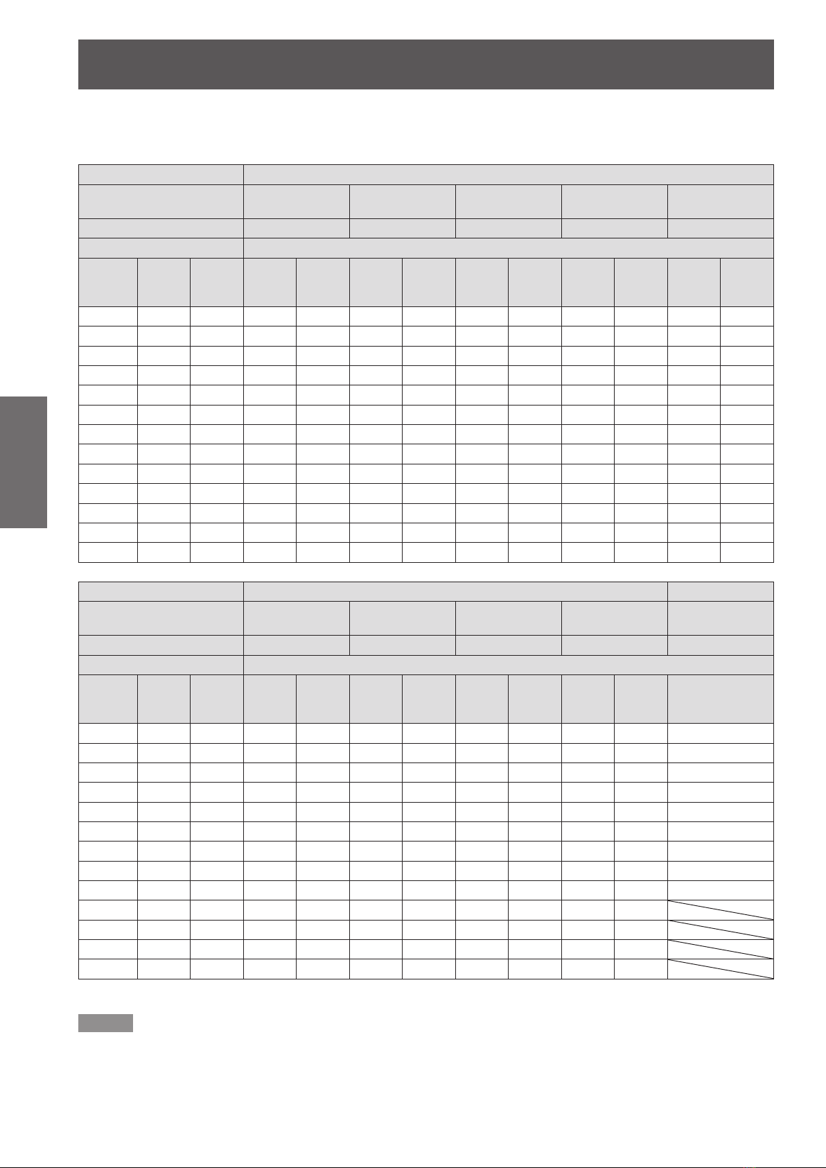
Setting up
30
- ENGLISH
Getting Started
Q
For the screen aspect ratio of 4 : 3 (Unit : m)
Model number of
Screen dimensions Projection distance (L)
Screen
size (")
70 1.067 1.422 2.86 3.82 3.86 5.80 5.81 9.74 9.75 15.59 15.30 29.04
80 1.219 1.626 3.28 4.38 4.42 6.65 6.66 11.15 11.16 17.83 17.55 33.24
90 1.372 1.829 3.70 4.94 4.98 7.49 7.50 12.56 12.57 20.07 19.79 37.44
100 1.524 2.032 4.12 5.50 5.55 8.33 8.34 13.97 13.98 22.31 22.03 41.64
120 1.829 2.438 4.96 6.62 6.67 10.02 10.03 16.79 16.80 26.79 26.51 50.04
150 2.286 3.048 6.21 8.30 8.36 12.55 12.56 21.02 21.03 33.52 33.24 62.64
200 3.048 4.064 8.31 11.11 11.17 16.77 16.78 28.07 28.07 44.72 44.44 83.63
250 3.810 5.080 10.41 13.91 13.99 20.99 21.00 35.12 35.12 55.93 55.65 104.63
300 4.572 6.096 12.51 16.71 16.80 25.21 25.22 42.16 42.17 67.14 66.86 125.63
350 5.334 7.112 14.60 19.51 19.61 29.43 29.44 49.21 49.22 78.34 78.07 146.63
400 6.096 8.128 16.70 22.31 22.43 33.65 33.66 56.26 56.26 89.55 89.28 167.63
500 7.620 10.160 20.89 27.92 28.05 42.09 42.10 70.35 70.36 111.96 111.69 209.62
600 9.144 12.192 25.09 33.52 33.68 50.53 50.54 84.45 84.45 134.38 134.11 251.62
Lens type Zoom lens
projection lens
Throw ratio
Effective
height
(SH)
Û
Effective
width
(SW)
ET-D75LE1 ET-D75LE2 ET-D75LE3 ET-D75LE4 ET-D75LE8
2.0–2.7 : 1 2.7–4.1 : 1 4.1–6.9 : 1 6.9–11.0 : 1 10.9–20.6 : 1
Min.
(LW)
Max.
(LT)
Min.
(LW)
Max.
(LT)
Min.
(LW)
Max.
(LT)
Min.
(LW)
Max.
(LT)
Min.
(LW)
Max.
(LT)
Lens type Zoom lens Fixed-focus lens
Model number of
projection lens
(SH)
Û
Effective
width
(SW)
Throw ratio
Screen dimensions Projection distance (L)
Screen
size (")
100 1.524 2.032 2.77 3.32 3.88 5.02 4.99 7.26 7.21 14.03 2.08
120 1.829 2.438 3.34 4.00 4.68 6.05 6.01 8.74 8.68 16.87 2.51
150 2.286 3.048 4.19 5.01 5.87 7.58 7.53 10.95 10.87 21.13 3.16
200 3.048 4.064 5.60 6.71 7.85 10.15 10.07 14.64 14.53 28.23 4.24
250 3.810 5.080 7.01 8.40 9.83 12.71 12.61 18.32 18.20 35.33 5.32
300 4.572 6.096 8.43 10.10 11.82 15.28 15.15 22.01 21.86 42.43 6.40
350 5.334 7.112 9.84 11.80 13.80 17.84 17.68 25.70 25.52 49.53
400 6.096 8.128 11.26 13.49 15.78 20.40 20.22 29.39 29.18 56.64
500 7.620 10.160 14.08 16.88 19.75 25.53 25.30 36.76 36.50 70.84
600 9.144 12.192 16.91 20.27 23.72 30.66 30.38 44.14 43.83 85.04
Effective
height
70 1.067 1.422 1.92 2.30 2.69 3.48 3.47 5.05 5.01 9.77 1.43
80 1.219 1.626 2.21 2.64 3.09 3.99 3.98 5.78 5.75 11.19 1.64
90 1.372 1.829 2.49 2.98 3.49 4.51 4.49 6.52 6.48 12.61 1.86
ET-D75LE6 ET-D75LE10 ET-D75LE20 ET-D75LE30 ET-D75LE5
1.4–1.6 : 1 1.9–2.5 : 1 2.5–3.6 : 1 3.6–6.9 : 1 1.0 : 1
Min.
(LW)
Max.
(LT)
Min.
(LW)
Max.
(LT)
Min.
(LW)
Max.
(LT)
Min.
(LW)
Max.
(LT)
Fixed
Û
The throw ratio is based on the value during projection onto a 150-inch screen size.:
Note
The projection distances listed here involve an error of ±5 %.
z
When geometric adjustment is used, compensation is made so that the screen size becomes smaller than the specied
z
size.
 Loading...