

Page 1
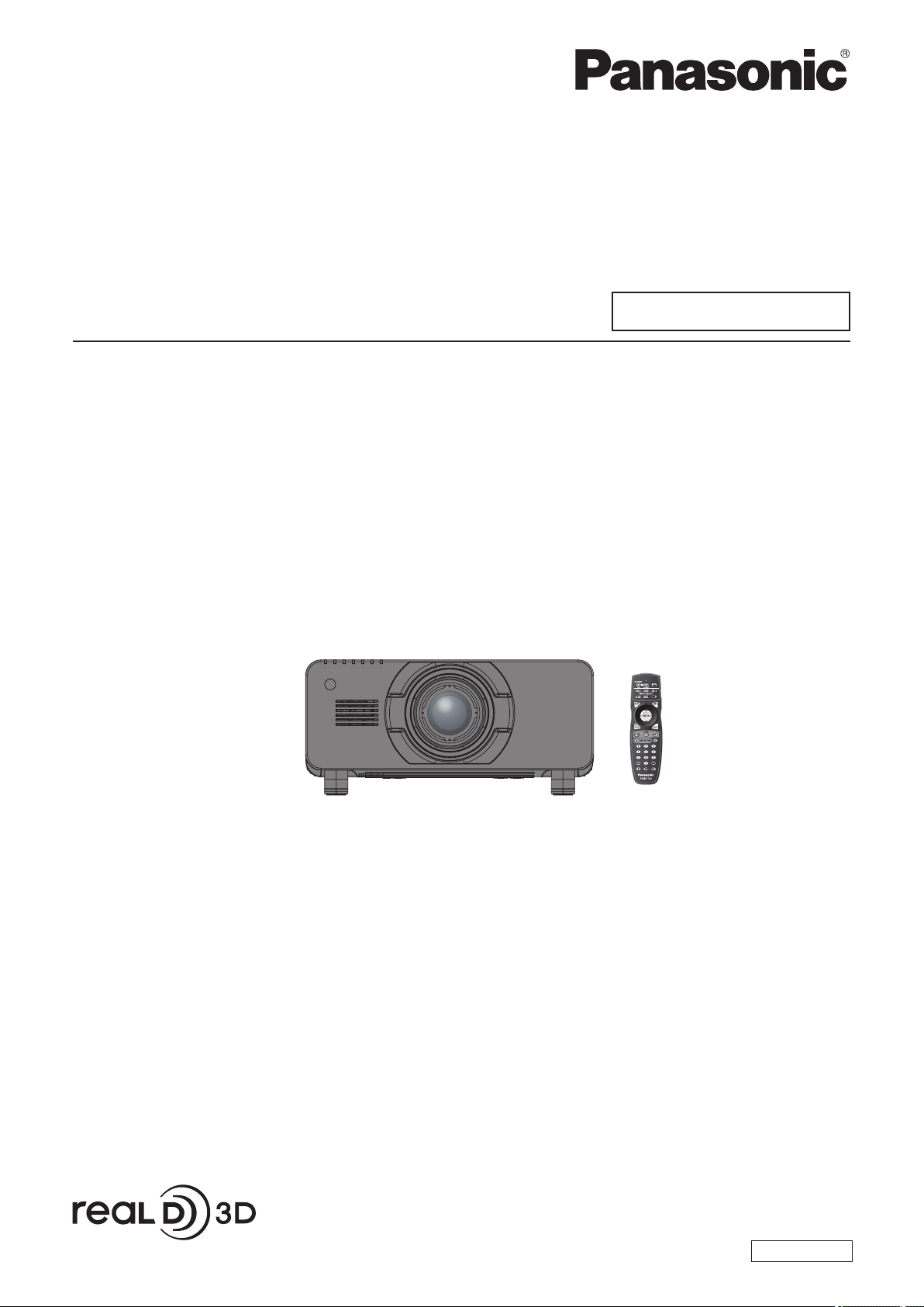
Operating Instructions
Functional Manual
DLPTM Projector
Model No.
PT-DZ21KU
Commercial Use
PT-DS20KU
PT-DW17KU
7KHSURMHFWLRQOHQVLVVROGVHSDUDWHO\
Thank you for purchasing this Panasonic product.
■ Before operating this product, please read the instructions carefully and save this manual
for future use.
■ Before using your projector, be sure to read “Read this rst!” (
pages 2 to 10).
ENGLISH
TQBJ0418-1
Page 2
Information
Read this rst!
Read this rst!
Information
Important
WARNING: TO REDUCE THE RISK OF FIRE OR ELECTRIC SHOCK, DONOT EXPOSE THIS PRODUCT
CAUTION: This equipment is equipped with a three-pin grounding-type power
TO RAIN OR MOISTURE.
The lightning ash with arrowhead symbol, within an equilateral triangle, is intended to alert the
user to the presence of uninsulated “dangerous voltage” within the product’s enclosure that may
be of sufcient magnitude to constitute a risk of electric shock to persons.
The exclamation point within an equilateral triangle is intended to alert the user to the presence of
important operating and maintenance (servicing) instructions in the literature accompanying the
product.
plug. Do not remove the grounding pin on the power plug. This plug
will only t a grounding-type power outlet. This is a safety feature. If
you are unable to insert the plug into the outlet, contact an electrician.
Do not defeat the purpose of the grounding plug.
Do not remove
2 - ENGLISH
Page 3

Read this rst!
FCC NOTICE (USA)
Verication
Model Number: PT-DZ21KU/PT-DS20KU/PT-DW17KU
Trade Name: Panasonic
Responsible Party: Panasonic Corporation of North America
Address: One Panasonic Way, Secaucus, NJ 07094
Telephone number: (877)803-8492
E-mail: projectorsupport@us.panasonic.com
This device complies with Part 15 of the FCC Rules.
Operation is subject to the following two conditions:
(1) This device may not cause harmful interference, and (2) this device must accept any interference received,
including interference that may cause undesired operation.
To assure continued compliance, follow the attached installation instructions and do not make any unauthorized
modications.
CAUTION:
This equipment has been tested and found to comply with the limits for a Class A digital device, pursuant
to part 15 of the FCC Rules. These limits are designed to provide reasonable protection against harmful
interference when the equipment is operated in a commercial environment. This equipment generates, uses,
and can radiate radio frequency energy and, if not installed and used in accordance with the instruction
manual, may cause harmful interference to radio communications. Operation of this equipment in a residential
area is likely to cause harmful interference in which case the user will be required to correct the interference at
his own expense.
Important
Information
NOTIFICATION (Canada)
This class A digital apparatus complies with Canadian ICES-003.
WARNING:
zNot for use in a computer room as dened in the Standard for the Protection of Electronic Computer/Data
Processing Equipment, ANSI/NFPA 75.
zFor permanently connected equipment, a readily accessible disconnect device shall be incorporated in the
building installation wiring.
zFor pluggable equipment, the socket-outlet shall be installed near the equipment and shall be easily
accessible.
NOTICE USA only:
zThis product has a High Intensity Discharge (HID) lamp that contains mercury. Disposal may be regulated
in your community due to environmental considerations. For disposal or recycling information, please visit
Panasonic website: http://www.panasonic.com/environmental or call 1-888-769-0149.
For USA-California Only
This product contains a CR Coin Cell Lithium Battery which contains Perchlorate Material – special handling
may apply.
See www.dtsc.ca.gov/hazardouswaste/perchlorate
ENGLISH - 3
Page 4

Read this rst!
Information
Important
WARNING:
The wall outlet or the circuit breaker shall be installed near the equipment and shall be easily
accessible when problems occur. If the following problems occur, cut off the power supply
immediately.
Continued use of the projector in these conditions will result in re or electric shock.
During a thunderstorm, do not touch the projector or the cable.
Electric shocks can result.
Do not do anything that might damage the power cord or the power plug.
If the power cord is used while damaged, electric shocks, short-circuits or re will result.
Completely insert the power plug into the wall outlet and the power connector into the projector terminal.
If the plug is not inserted correctly, electric shocks or overheating will result.
Do not use anything other than the provided power cord.
Failure to observe this will result in re or electric shocks.
Clean the power plug regularly to prevent it from becoming covered in dust.
Failure to observe this will cause a re.
Do not handle the power plug and power connector with wet hands.
Failure to observe this will result in electric shocks.
Do not overload the wall outlet.
If the power supply is overloaded (ex., by using too many adapters), overheating may occur and re will result.
POWER
zIf foreign objects or water get inside the projector, cut off the power supply.
zIf the projector is dropped or the cabinet is broken, cut off the power supply.
zIf you notice smoke, strange smells or noise coming from the projector, cut off the power supply.
Please contact an Authorized Service Center for repairs, and do not attempt to repair the projector yourself.
zDo not damage the power cord, make any modications to it, place it near any hot objects, bend it
excessively, twist it, pull it, place heavy objects on top of it or wrap it into a bundle.
Ask an Authorized Service Center to carry out any repairs to the power cord that might be necessary.
zDo not use plugs which are damaged or wall outlets which are coming loose from the wall.
zIf dust builds up on the power plug, the resulting humidity can damage the insulation.
zIf not using the projector for an extended period of time, pull the power plug out from the wall outlet.
Pull the power plug out from the wall outlet and wipe it with a dry cloth regularly.
ON USE/INSTALLATION
Do not place the projector on soft materials such as carpets or sponge mats.
Doing so will cause the projector to overheat, which can cause burns, re or damage to the projector.
Do not set up the projector in humid or dusty places or in places where the projector may come into
contact with oily smoke or steam, ex. a bathroom.
Using the projector under such conditions will result in re, electric shocks or deterioration of components.
Deterioration of components (such as ceiling mount brackets) may cause the projector which is mounted on
the ceiling to fall down.
Do not install this projector in a place which is not strong enough to take the full weight of the
projector or on top of a surface which is sloped or unstable.
Failure to observe this will cause projector to fall down or tip over the projector, and severe injury or damage
could result.
4 - ENGLISH
Page 5

Read this rst!
WARNING:
Do not cover the air intake/exhaust ports or place anything within 500 mm (20") of them.
Doing so will cause the projector to overheat, which can cause re or damage to the projector.
zDo not place the projector in narrow, badly ventilated places.
zDo not place the projector on cloth or papers, as these materials could be drawn into the air inlet port.
Do not place your hands or other objects close to the air exhaust port.
Doing so will cause burns or damage your hands or other objects.
zHeated air comes out of the air exhaust port. Do not place your hands or face, or objects which cannot
withstand heat close to this port.
Do not look at or place your skin into the light emitted from the lens while the projector is being used.
Doing so can cause burns or loss of sight.
zExtremely strong light is emitted from the projector’s lens. Do not look at or place your hands directly into
this light.
zBe especially careful not to let young children look into the lens. In addition, turn off the power and
disconnect the power plug when you are away from the projector.
Never attempt to remodel or disassemble the projector.
High voltages can cause re or electric shocks.
zFor any inspection, adjustment and repair work, please contact an Authorized Service Center.
Do not project an image with the lens cover of the projection lens (optional) attached.
Doing so can cause re.
Do not allow metal objects, ammable objects, or liquids to enter inside of the projector. Do not allow
the projector to get wet.
Doing so may cause short circuits or overheating, and result in re, electric shock, or malfunction of the
projector.
zDo not place containers of liquid or metal objects near the projector.
zIf liquid enters inside of the projector, consult your dealer.
zParticular attention must be paid to children.
Use the ceiling mount bracket specied by Panasonic.
Using the ceiling mount bracket other than the specied one will result in falling accidents.
zAttach the supplied safety cable to the ceiling mount bracket to prevent the projector from falling down.
Installation work (such as ceiling mount bracket) should only be carried out by a qualied technician.
If installation is not carried out and secured correctly it can cause injury or accidents, such as electric shocks.
zDo not use anything other than an authorized ceiling mount bracket.
zBe sure to use the wire provided with the ceiling mount bracket as an extra safety measure to prevent the
projector from falling down. (Install in a different location to the ceiling mount bracket.)
Important
Information
ENGLISH - 5
Page 6

Read this rst!
Information
Important
WARNING:
Do not use or handle the batteries improperly, and refer to the following.
Failure to observe this will cause burns, batteries to leak, overheat, explode or catch re.
If the battery uid leaks, do not touch it with bare hands, and take the following measures if necessary.
Do not remove unspecied screws during the lamp unit replacement.
Doing so can cause electric shocks, burns, or injury.
Do not disassemble the lamp unit.
If the lamp breaks, it could cause injury.
Lamp replacement
The lamp has high internal pressure. If improperly handled, an explosion and severe injury or accidents will
result.
Do not use the supplied power cord with devices other than this projector.
Keep accessories (lens xing screws, etc.) out of the reach of small children.
Accidentally swallowing them can cause physical harm.
Remove the depleted batteries from the remote control promptly.
ACCESSORIES
zUse AA/R6 batteries.
zDo not use unspecied batteries.
zDo not use chargeable batteries.
zDo not disassemble dry cell batteries.
zDo not heat the batteries or place them into water or re.
zDo not allow the + and – terminals of the batteries to come into contact with metallic objects such as
necklaces or hairpins.
zDo not store batteries together with metallic objects.
zStore the batteries in a plastic bag and keep them away from metallic objects.
zMake sure the polarities (+ and –) are correct when inserting the batteries.
zDo not use a new battery together with an old battery or mix different types of batteries.
zDo not use batteries with the outer cover peeling away or removed.
zBattery uid on your skin or clothing could result in skin inammation or injury.
Rinse with clean water and seek medical advice immediately.
zBattery uid coming in contact with your eyes could result in loss of sight.
In this case, do not rub your eyes. Rinse with clean water and seek medical advice immediately.
zThe lamp can easily explode if struck against hard objects or dropped.
zBefore replacing the lamp unit, be sure to turn the power off and to disconnect the power plug from the wall
outlet.
Electric shocks or explosions can result if this is not done.
zWhen replacing the lamp unit, turn the power off and allow the lamp to cool for at least one hour before
handling it otherwise it can cause burns.
zBe careful to hold the lamp unit cover and to loosen the lamp unit cover xing screws with the projector
installed upward in the vertical direction since the lamp unit cover may open and the lamp case may drop
off on its weight.
This can cause severe injury or accidents.
zWhen you loosen or x the lamp case xing screws with the projector installed upward in the vertical
direction, make sure to hold the lamp case handle since the lamp case may drop off on its weight.
This can cause severe injury or accidents.
zUsing the supplied power cord with devices other than this projector may cause short circuits or
overheating, and result in electric shock or re.
zIf you believe that parts have been swallowed, seek medical advice immediately.
zLeaving them in the unit may result in uid leakage, overheating, or explosion of the batteries.
6 - ENGLISH
Page 7

Read this rst!
CAUTION:
POWER
When disconnecting the power cord, be sure to hold the power plug and power connector.
If the power cord itself is pulled, the lead will become damaged, and re, short-circuits or serious electric
shocks will result.
When not using the projector for an extended period of time, disconnect the power plug from the wall
outlet and remove the batteries from the remote control.
Failure to do so may result in re or electric shock.
Disconnect the power plug from the wall outlet before carrying out any cleaning and replacing the unit.
Failure to do so may result in electric shock.
ON USE/INSTALLATION
Do not place heavy objects on top of the projector.
Failure to observe this will cause the projector to become unbalanced and fall, which could result in damage or
injury. The projector will be damaged or deformed.
Do not put your weight on this projector.
You could fall or the projector could break, and injury will result.
zBe especially careful not to let young children stand or sit on the projector.
Do not place the projector in extremely hot locations.
Doing so will cause the outer casing or internal components to deteriorate, or result in re.
zTake particular care in locations exposed to direct sunlight or near stoves.
Do not place your hands in the openings beside the optical lens, while shifting the lens.
Failure to observe this could cause injury.
Do not stand in front of the lens while the projector is being used.
Doing so can cause damage and burns to clothing.
zExtremely strong light is emitted from the projector’s lens.
Do not place objects in front of the lens while the projector is being used.
Doing so can cause damage to the object and can cause the set to malfunction.
zExtremely strong light is emitted from the projector’s lens.
Always disconnect all cables before moving the projector.
Moving the projector with cables still attached can damage the cables, which will cause re or electric shocks
to occur.
Important
Information
ACCESSORIES
Do not use the old lamp unit.
If used it could cause lamp explosion.
If the lamp has broken, ventilate the room immediately. Do not touch or bring your face close to the
broken pieces.
Failure to observe this will cause the user to absorb the gas which was released when the lamp broke and which
contains nearly the same amount of mercury as uorescent lamps, and the broken pieces will cause injury.
zIf you believe that you have absorbed the gas or that the gas has got into your eyes or mouth, seek
medical advice immediately.
zAsk your dealer about replacing the lamp unit and check the inside of the projector.
Do not attach the air lter unit while it is wet.
Doing so may result in electric shock or malfunctions.
zAfter you clean the air lter units, dry them thoroughly before reattaching them.
Do not touch the fan with your ngers or any other parts of your body when replacing the lamp unit.
Doing so can cause injury.
Ask your dealer about cleaning inside the projector once a year.
Continuous use while dust is accumulated inside the projector may result in re.
zFor cleaning fee, ask your dealer.
When not using the projector for an extended period of time, remove the batteries from the remote control.
Failure to observe this will cause the batteries to leak, overheat, catch re or explode, which may result in re
or contamination of surrounding area.
ENGLISH - 7
Page 8

Read this rst!
Information
Important
CAUTION:
Those with a medical history of oversensitivity to light, heart problems, or poor physical health should
not view 3D images.
This may lead to a worsening of medical conditions.
If you feel tiredness or discomfort, or other abnormality while viewing with 3D Eyewear, discontinue
viewing.
Continuing use may cause health problems. Take a break as necessary.
When viewing 3D movies, aim to view one movie at a time and take a break as necessary.
When viewing 3D images, for example when playing 3D games or using a PC where two way interaction
is possible, take an appropriate break every 30 to 60 minutes.
Watching for long periods of time may cause eye fatigue.
When preparing contents, use contents properly created to be used for 3D.
This may cause eye fatigue or health problems.
When viewing 3D images, pay attention to people and objects in the vicinity.
3D video may be mistaken for actual objects, and the related bodily movements can cause damage to objects
and lead to injury.
Use 3D Eyewear when viewing 3D videos.
Do not tilt your head when viewing with 3D Eyewear.
Those who are near or far sighted, those with weaker eyesight in one eye, or those with astigmatism
should use corrective glasses etc. when using 3D Eyewear.
If the image appears distinctly double when viewing 3D video, discontinue viewing.
Watching for long periods of time may cause eye fatigue.
View at a distance of at least three times the effective height of the screen.
Viewing at distance closer than the recommended distance may cause eye fatigue. As with movies, if there are
black bands at the top and bottom of the video, view at a distance of 3 times or more of the height of the video
section.
Children younger than 5 or 6 years old should not use 3D Eyewear.
As it is difcult to gauge the reactions of children to fatigue and discomfort their condition may worsen
suddenly.
If a child uses the 3D Eyewear, guardians should beware of the child’s eyes becoming tired.
VIEWING 3D VIDEO (PT-DZ21KU and PT-DS20KU only)
8 - ENGLISH
Page 9
Brazil Only
Brasil Apenas
Read this rst!
Manuseio de baterias usadas
BRASIL
Após o uso, as pilhas e /ou baterias poderão
ser entregues ao estabelecimento comercial
ou rede de assistência técnica autorizada.
Cobrir os terminais positivo (+) e negativo (-) com uma ta isolante adesiva, antes de depositar numa caixa
destinada para o recolhimento. O contato entre partes metálicas pode causar vazamentos, gerar calor, romper
a blindagem e produzir fogo.
Não desmonte, não remova o invólucro, nem amasse a bateria. O gás liberado pela bateria pode irritar a
garganta, danicar o lacre do invólucro ou o vazamento provocar calor, ruptura da blindagem e produzir fogo
devido ao curto circuito dos terminais.
Não incinere nem aqueça as baterias, elas não podem car expostas a temperaturas superiores a 100 °C (212
°F). O gás liberado pela bateria pode irritar a garganta,
danicar o lacre do invólucro ou o vazamento provocar calor, ruptura da blindagem e produzir fogo devido ao
curto circuito dos terminais provocado internamente.
Evite o contato com o liquido que vazar das baterias. Caso isto ocorra, lave bem a parte afetada com bastante
água. Caso haja irritação, consulte um médico.
Remoção das baterias
Important
Information
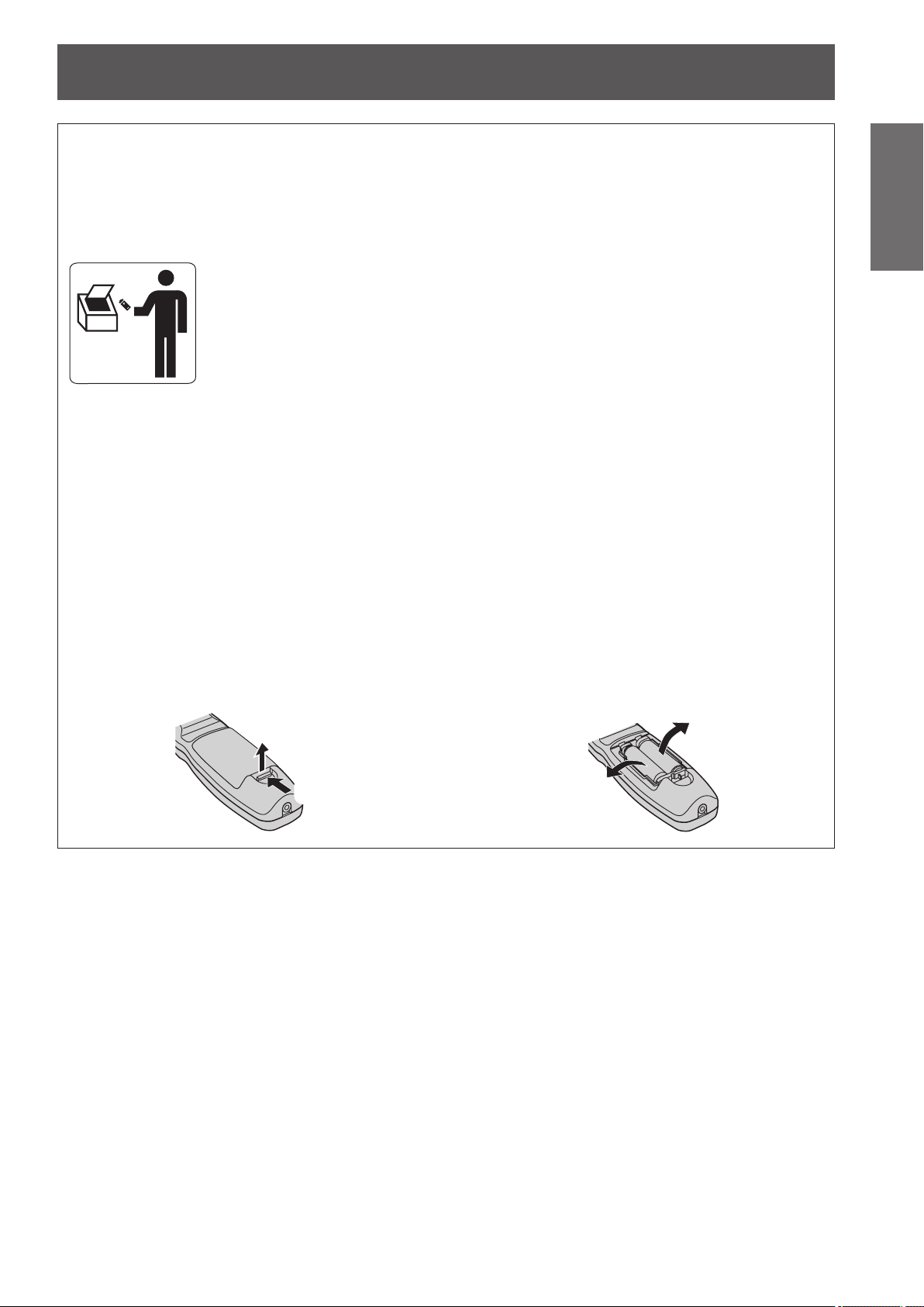
1. Pressione a guia e levante a tampa.
(ii)
(i)
2. Remova as baterias.
ENGLISH - 9
Page 10

Read this rst!
Information
Important
Trademarks
• Microsoft®, Windows®, Windows Vista®, and Internet Explorer® are the registered trademarks or trademarks of
Microsoft Corporation in the United States and/or other countries.
• Mac, Mac OS, OS X, and Safari are the trademarks of Apple Inc. registered in the United States and other
countries.
• PJLinkTM is a trademark or pending trademark in Japan, the United States, and other countries and regions.
• HDMI, the HDMI logo and High-Denition Multimedia Interface are trademarks or registered trademarks of
HDMI Licensing LLC.
• VGA and XGA are trademarks of International Business Machines Corporation.
• SVGA is a registered trademark of the Video Electronics Standards Association.
• RealD 3D is a trademark of RealD Inc.
• The font used in the on-screen displays is a Ricoh bitmap font, which is manufactured and sold by Ricoh
Company, Ltd.
• Other names, company names or product names used in these operating instructions are the trademarks or
registered trademarks of their respective holders.
Please note that the operating instructions do not include the ® and TM symbols.
Illustrations in these operating instructions
• Note that illustrations of the projector and screens may differ from the ones you actually see.
Page references
• In these instructions, references to pages are indicated as: ( page 00).
Term
• In these instructions, the “Wireless/wired remote control unit” accessories are referred to as the “Remote
control”.
10 - ENGLISH
Page 11
Quick StepsQuick Steps
Features of the ProjectorFeatures of the Projector
Small size & ultra-high
luminance
An ultra high luminance of
▶
*1
20 000 lm
having a small size due to the
unique optical system, cooling, and
mechanism design.
*1: For PT-DZ21KU and PT-DS20KU. PT-DW17KU has a
luminance of 17 000 lm.
is achieved while
Easy setup and improved
serviceability
Extensive lineup of optional lenses
▶
allow more exible setup of the
projector.
Improved cost performance
For details, see the corresponding pages.
1. Set up the projector.
( page 28)
2. Attach the projection lens
(optional accessories)
page 43)
(
3. Connect with other
devices. ( page 44)
in maintenance fee
The new lter reduces the
▶
maintenance cost.
4. Connect the power cord.
( page 48)
5. Switch on the projector.
( page 50)
6. Make initial settings.
*1
( page 21)
7. Select the input signal.
( page 52)
8. Adjust the image.
( page 52)
*1: These are the steps to be taken when you switch on the
power for the rst time after purchasing the projector.
ENGLISH - 11
Page 12

Contents
Contents
Be sure to read “Read this rst!”. (
pages
2 to 10)
Information
Important
Important Information
Read this rst! ............................................ 2
Precautions for use ...................................15
Preparation Getting Started Basic Operation Settings Maintenance Appendix
Preparation
Start-up display .........................................21
About your projector ................................ 22
Using the remote control ......................... 27
Getting Started
Setting up .................................................. 28
Attaching/removing the projection lens
Connecting ............................................... 44
Basic Operation
Switching on/off the projector ................. 48
Projecting.................................................. 52
Cautions when transporting .............................15
Cautions when installing .................................. 15
Security ...........................................................18
Disposal .......................................................... 18
Cautions on use .............................................. 18
Accessories ....................................................19
Optional accessories .......................................20
Remote control ................................................22
Projector body .................................................24
Inserting and removing the batteries ................ 27
Setting Remote control ID numbers .................27
Connecting to the projector with a cable ..........27
Projection method ........................................... 28
Parts for ceiling mount (optional) ..................... 29
Screen size and throw distance .......................29
Adjusting adjustable feet ................................. 42
(optional accessory) ............................. 43
Attaching the projection lens ............................43
Removing the projection lens ..........................43
Before connecting ........................................... 44
Connecting example: AV equipment ................ 45
Connecting example: Computers .....................47
Connecting the power cord ..............................48
Power indicator ............................................... 49
Switching on the projector ...............................50
Making adjustments and selections .................50
Switching off the projector ............................... 51
Select the input signal .....................................52
Adjusting the focus, zoom, and shift ................ 52
Moving the lens to the home position ...............53
Adjustment range by the lens position shift
(optical shift) .............................................54
Adjusting the lens mounter when the focus
is unbalanced ...........................................55
Remote control operation ........................ 58
Using the shutter function ................................58
Using the on-screen display function ...............58
Switching the input ..........................................58
Using the STATUS function .............................59
Using the Automatic setup function ..................59
Using the Function button ................................59
Displaying the internal test pattern ................... 60
Changing the picture aspect ratio .................... 60
Settings
Menu navigation ........................................61
Navigating through the menu ........................... 61
Main menu ......................................................62
Sub-menu .......................................................63
[PICTURE] menu ....................................... 65
[PICTURE MODE] ...........................................65
[CONTRAST] ..................................................66
[BRIGHTNESS] ............................................... 66
[COLOR] ......................................................... 66
[TINT] ..............................................................66
[COLOR TEMPERATURE] ..............................66
[GAMMA] ........................................................68
[SYSTEM DAYLIGHT VIEW] ...........................68
[SHARPNESS] ................................................68
[NOISE REDUCTION] .....................................69
[DYNAMIC IRIS] ..............................................69
[SYSTEM SELECTOR] ...................................70
Making sRGB compliant images ...................... 71
[POSITION] menu ..................................... 72
[SHIFT] ...........................................................72
[ASPECT] .......................................................72
[ZOOM] ........................................................... 73
[CLOCK PHASE] .............................................74
[GEOMETRY] (PT-DZ21KU and
PT-DS20KU only) .....................................74
[KEYSTONE] (PT-DW17KU only) ....................76
[ADVANCED MENU] ................................. 77
[DIGITAL CINEMA REALITY]...........................77
[BLANKING] ....................................................77
[INPUT RESOLUTION] ....................................78
[CLAMP POSITION] ........................................ 78
[EDGE BLENDING] .........................................78
[FRAME RESPONSE] .....................................80
[FRAME LOCK] (PT-DZ21KU and
PT-DS20KU only) .....................................80
[RASTER POSITION] ......................................80
12 - ENGLISH
Page 13

Contents
[DISPLAY LANGUAGE] menu ...................81
Changing the display language ........................81
[3D SETTINGS] menu (PT-DZ21KU and
PT-DS20KU only) .................................. 82
[3D SYSTEM SETTING] ..................................82
[3D SYNC SETTING] ......................................82
[3D SIMUL INPUT SETTING] ..........................83
[3D INPUT FORMAT] ...................................... 84
[LEFT/RIGHT SWAP] ...................................... 84
[3D COLOR MATCHING] ................................ 84
[3D PICTURE BALANCE] ...............................85
[DARK TIME SETTING] ..................................85
[3D FRAME DELAY]........................................86
[3D TEST MODE] ............................................86
[3D TEST PATTERN] ...................................... 86
[SAFETY PRECAUTIONS MESSAGE] ........... 87
[3D SAFETY PRECAUTIONS] ........................ 87
[DISPLAY OPTION] menu ......................... 88
[COLOR MATCHING] ......................................88
[LARGE SCREEN CORRECTION] ..................89
[SCREEN SETTING] (PT-DZ21KU and
PT-DS20KU only) .....................................90
[AUTO SIGNAL] ..............................................90
[AUTO SETUP] ...............................................91
[RGB IN] (supported during RGB signal
input only) .................................................92
[DVI-D IN] ........................................................92
[HDMI IN] ........................................................93
[SDI IN] (PT-DZ21KU and PT-DS20KU only) ...93
[ON-SCREEN DISPLAY] .................................94
[BACK COLOR] ..............................................95
[STARTUP LOGO] ..........................................95
[UNIFORMITY] ................................................95
[SHUTTER SETTING] ..................................... 96
[FREEZE] ........................................................96
[WAVEFORM MONITOR] ................................96
[CUT OFF] ......................................................98
[PROJECTOR SETUP] menu .................... 99
[PROJECTOR ID] ............................................ 99
[PROJECTION METHOD] ...............................99
[COOLING CONDITION] ...............................100
[HIGH ALTITUDE MODE] .............................. 100
[LAMP SELECT] ...........................................100
[LAMP RELAY] .............................................. 101
[BRIGHTNESS CONTROL] ........................... 102
[STANDBY MODE] ........................................ 106
[SCHEDULE] .................................................106
[RS-232C] ..................................................... 108
[STATUS] ...................................................... 109
[NO SIGNAL SHUT-OFF] .............................. 110
[REMOTE2 MODE] ....................................... 110
[FUNCTION BUTTON] .................................. 110
[DATE AND TIME] ......................................... 110
[LENS CALIBRATION] ...................................111
[LENS MEMORY] .......................................... 112
[SAVE ALL USER DATA] ............................... 113
[LOAD ALL USER DATA] .............................. 113
[INITIALIZE]................................................... 114
[SERVICE PASSWORD] ............................... 114
[P IN P] menu ........................................... 115
Using P IN P functions ................................... 115
Setting P IN P functions ................................. 115
[TEST PATTERN] menu ...........................117
[TEST PATTERN] .......................................... 117
[SIGNAL LIST] menu ...............................118
Registering a signal to the list ........................ 118
Renaming the registered data ....................... 118
Deleting the registered data ........................... 118
Protecting the registered data ........................ 119
Expanding signal lock-in range ...................... 119
Managing the sub memory list ....................... 120
[SECURITY] menu ...................................121
[SECURITY PASSWORD] ............................. 121
[SECURITY PASSWORD CHANGE] ............. 121
[DISPLAY SETTING] .....................................122
[TEXT CHANGE] ........................................... 122
[CONTROL DEVICE SETUP] ........................ 122
[CONTROL DEVICE PASSWORD CHANGE]
...124
[NETWORK] menu ...................................125
[NETWORK SETUP] ..................................... 125
[NETWORK CONTROL] ............................... 125
[NETWORK STATUS] ................................... 125
Network connections ..................................... 126
Accessing from the Web browser ..................127
Maintenance
Lamp/Temperature/Filter Indicators .......142
Managing the indicated problems ..................142
Maintenance/replacement .......................144
Before maintaining/replacing the unit ............. 144
Maintenance ................................................. 144
Replacing the unit ..........................................146
Troubleshooting ......................................151
Self-diagnosis display .............................153
Important
Information
PreparationGetting StartedBasic OperationSettingsMaintenanceAppendix
ENGLISH - 13
Page 14

Contents
Information
Important
Appendix
Technical information ..............................156
Preparation Getting Started Basic Operation Settings Maintenance Appendix
Specications ..........................................172
Dimensions ..............................................175
Ceiling mount bracket safeguards .........176
Index ........................................................177
PJLink protocol ..............................................156
Control commands via LAN ........................... 157
<SERIAL IN>/<SERIAL OUT> terminal .......... 160
<REMOTE 2 IN> terminal .............................. 164
Two window display combination list ..............165
Control device password ............................... 166
Upgrade kit (only supports PT-DZ21KU and
PT-DS20KU) ...........................................166
List of compatible signals ...............................167
14 - ENGLISH
Page 15

Precautions for use
Precautions for use
Cautions when transporting
zThe projection lens (optional accessory) is susceptible to effects due to vibration or impact. Make sure to
remove the lens when transporting.
zWhen transporting the projector, hold it securely by its bottom and avoid excessive vibration and impacts. Not
doing so may damage the internal parts and result in malfunctions.
zDo not transport the projector with the adjustable feet extended. Doing so may damage the adjustable feet.
Cautions when installing
■After removing the projection lens (optional accessory), attach the dustproof sponge included with the projector.
If the cover is not attached, dust will accumulate inside and may cause malfunctions.
■Do not set up the projector outdoors.
The projector is designed for indoor use only.
■Do not set up the projector in the following locations.
Places where vibration and impacts occur such as in a car or vehicle: Doing so may damage the internal
z
parts and result in malfunctions.
Near the exhaust of an air conditioner: Depending on the conditions of use, the screen may uctuate due
z
to the hot air from the air exhaust port or the heated or cooled air from the air conditioner. Make sure that
the exhaust from the projector or other equipment, or the air from the air conditioner does not blow toward
the front of the projector.
Near lights (studio lamps, etc.) where temperature changes greatly (“Operating environment” (
z
Doing so may shorten the life of the lamp or result in deformation of the outer case and malfunctions.
Near high-voltage power lines or near motors: Doing so may interfere with the operation of the projector.
z
Place where there is a high-power laser equipment: It may cause malfunction in DLP chips when the laser
z
beam enters the lens.
■Be sure to ask a specialized technician or your dealer when installing the
page 174)):
Important
Information
product to a ceiling.
If the product is to be installed hanging from the ceiling, purchase an optional Ceiling Mount Attachment.
Model No.: ET-PKD510H (for high ceilings), ET-PKD510S (for low ceilings)
■Lens focus
The high clarity projection lens is thermally affected by the light from the light source, making the focus
unstable in the period just after switching on the power. Wait at least 30 minutes with the image projected
before adjusting the lens focus.
■Make sure to set [HIGH ALTITUDE MODE] to [ON] when using the projector
at elevations of 1 400 m (4 593 ft) or higher and lower than 2 700 m (8 858 ft)
above sea level.
Failure to do so may shorten the life of the internal parts and result in malfunctions.
■Make sure to set [HIGH ALTITUDE MODE] to [OFF] when using the projector
at elevations lower than 1 400 m (4 593 ft) above sea level.
Failure to do so may shorten the life of the internal parts and result in malfunctions.
■Do not install the projector at elevations of 2 700 m (8 858 ft) or higher above
sea level.
Doing so may shorten the life of the internal parts and result in malfunctions.
ENGLISH - 15
Page 16
Precautions for use
Information
Important
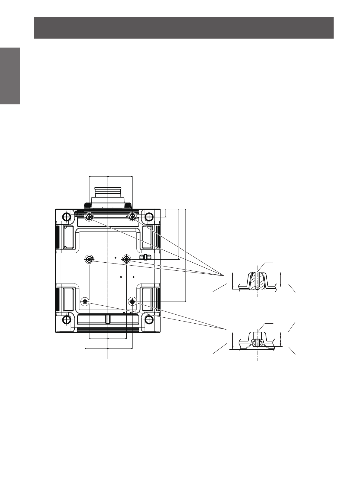
Bottom view
Unit: mm
■Do not use the projector tilted to the right or left
Using the projector at a vertical angle that exceeds 15° may reduce product life or result in malfunction.
■When installing and using the projector at an angle that exceeds 30°
vertically, set [COOLING CONDITION] (
Failure to observe this will result in malfunctions or shorten the life of the lamp or other components.
page 100).
■When a replacement lamp unit is used (for portrait mode), install it with the
terminals surface facing down
Do not use the projector tilted to the right and left, front and back.
Using the projector at an angle that exceeds 15° in either direction may reduce product life or result in
malfunction.
■Cautions when setting up the projector
When installing and using the projector with a method other than the oor standing installation using the
z
adjustable feet, x the projector using the six screw holes for ceiling mounting (see the gure below). (Screw
diameter: M6, tapping depth inside the set: 30 mm (1-3/16"), torque: 4 ± 0.5 N·m)
110
(4-11/32")
145
(5-23/32")
Model No. of ceiling mount bracket: ET-PKD510H (for high ceilings)
ET-PKD510S (for low ceilings)
48
(1-7/8")
110
(4-11/32")
135.5
(5-11/32")
110
(4-11/32")
145
(5-23/32")
298 (11-23/32")
548 (21-9/16")
30 mm (1-3/16")
30 mm (1-3/16")
Max. screw hole depth
Screw holes for ceiling mount
Torque: 4 ± 0.5 N·m
M6
25 mm (31/32")
Screw hole depthMax. screw hole depth
M6
Space
12 mm (15/32")
12 mm (15/32")
Embedded nut
(Screw hole depth)
16 - ENGLISH
Page 17
Precautions for use
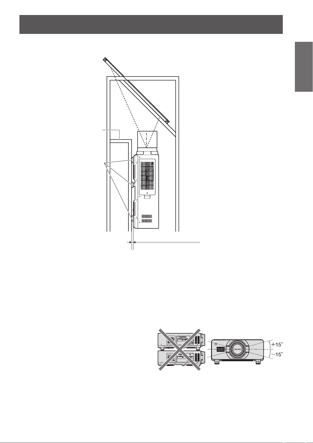
Make a clearance of at least 5 mm (0.2") between the projector bottom and setting surface by inserting
z
spacers (metallic) etc. between them.
0RXQW
6SDFHU
Important
Information
*DSPPRUPRUH
3OHDVHHQVXUHWKHLQIORZRI
DLULQWRWKHDLULQWDNHSRUW
7KLVFRXOGEHDUHDVRQIRU
WKHSURMHFWRUWRQRWZRUN
SURSHUO\
The adjustable feet can be removed if not needed in the installation. However, do not use the screw holes
z
where the adjustable feet was removed to x the projector in place.
Also, do not install other screws not specied in the instruction manuals of accessories in the adjustable
feet’s screw holes.
Doing so may damage the set.
Use the adjustable feet only for the oor standing installation and for adjusting the angle. Using it for other
z
purposes may damage the set.
Do not stack projectors on top of each other.
z
Do not use the projector tilted at an angle that
z
exceeds ±15° from the horizontal plane.
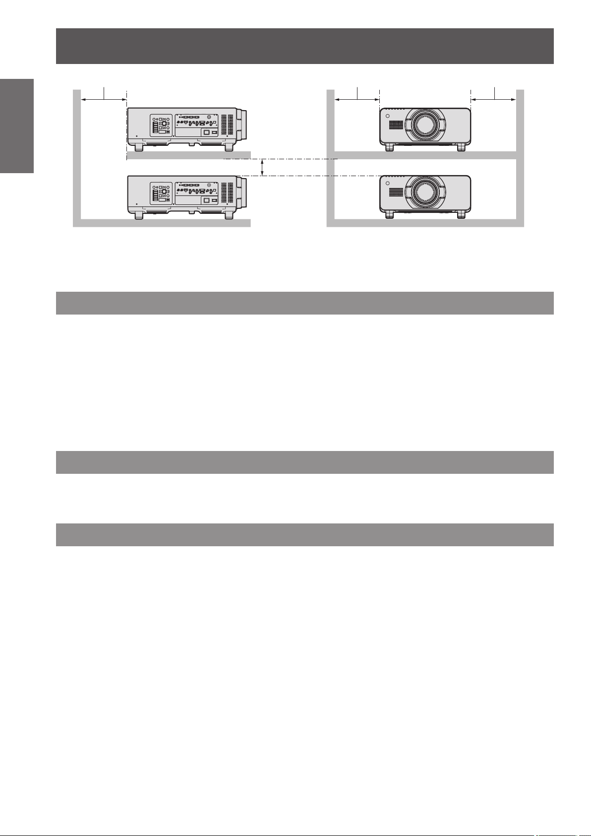
Prevent hot and cool air from the air
z
conditioning system to blow directly to the
ventilation ports (intake and exhaust) of the
projector.
Do not block the ventilation ports (intake and
z
exhaust) of the projector.
ENGLISH - 17
Page 18
Precautions for use
PPRUPRUH PPRUPRUH PPRUPRUH
Information
Important
Security
When using this product, take safety measures against the following incidents.
Take sufcient security measures. ( pages 121, 140)
PPRUPRUH
Do not install the projector in a conned space.
z
When it is necessary to install the projector in a conned space, install the air conditioning or ventilation
separately. Exhaust heat may accumulate when the ventilation is not enough, triggering the protection
circuit of the projector.
Personal information being leaked via this product
z
Unauthorized operation of this product by a malicious third party
z
Interfering or stopping of this product by a malicious third party
z
Make your password difcult to guess as much as possible.
z
Change your password periodically.
z
Panasonic Corporation or its afliate companies will never ask for your password directly. Do not divulge
z
your password in case you receive such inquiries.
The connecting network must be secured by a rewall, etc.
z
Set a password for the web control and restrict the users who can log in.
z
Disposal
To dispose of the product, ask your local authorities or dealer for correct methods of disposal.
The lamp contains mercury. When disposing of used lamp units, contact your local authorities or dealer for correct
methods of disposal.
Cautions on use
■To get a good picture quality
In order to view a beautiful image in higher contrast, prepare an appropriate environment. Draw curtains or
blinds over windows and turn off any lights near the screen to prevent outside light or light from indoor lamps
from shining onto the screen.
■Do not touch the surface of the projection lens with your bare hands.
If the surface of the projection lens becomes dirty from ngerprints or anything else, this will be magnied and
projected onto the screen. Please put the lens cover (accessory) on the projector when you do not use it.
■DLP chips
The DLP chips are precision-made. Note that in rare cases, pixels of high precision could be missing or
z
always lit. This is not a malfunction.
Directing a high-power laser beam onto the lens surface can damage the DLP chips.
z
■Do not move the projector while it is operating or subject it to vibration or
impact.
Doing so may shorten the service life of its internal components.
■Lamp
The luminous source of the projector is a high-pressure mercury lamp.
A high-pressure mercury lamp has the following characteristics.
18 - ENGLISH
Page 19
Precautions for use
The luminance of the lamp will decrease by duration of usage.
z
The lamp may burst with a loud sound or have its service life shortened because of shock, chipping, or
z
degradation due to cumulative operating time.
The lamp life varies greatly depending on individual differences and usage conditions. In particular,
z
frequent on/off switching of the power greatly deteriorate the lamp and affect the lamp life.
Continuous use for over 1 week will deteriorate the lamp. The degradation of the lamp due to continuous
z
usage can be reduced by lamp relay function. (
In rare cases, the lamps burst shortly after projection starts.
z
The risk of bursting increases when the lamp is used beyond its replacement cycle. Make sure to replace
z
the lamp unit regularly.
(“When to replace the lamp unit” ( page 148), “Replacing the lamp unit” ( page 148))
If the lamp bursts, gas contained inside of the lamp is released in a form of smoke.
z
It is recommended that you store replacement lamp units for contingency.
z
■Viewing 3D video (PT-DZ21KU and PT-DS20KU only)
The projector can display 3D video signals that are input by the “simultaneous”, “frame packing method”,
and “side by side” methods. You are required to prepare external devices for viewing 3D video (such as 3D
Eyewear, video signal output devices) which are suitable for your 3D system. For connections of the projector
and external devices, see the instructions of external devices you use. Refer to “List of 3D compatible signals”
( page 169) for the types of 3D video signals that can be used with the projector.
<Software information regarding this product>
© Panasonic Corporation 2012
This product is equipped with the following software:
(1) Software which is developed independently by or for Panasonic Corporation
(2) Software which is licensed under GNU GENERAL PUBLIC LICENSE
(3) Software which is licensed under GNU LESSER GENERAL PUBLIC LICENSE
For license conditions related to software in (2) and (3), refer to the provisions of the software licenses (GNU GENERAL PUBLIC
LICENSE and GNU LESSER GENERAL PUBLIC LICENSE) in the supplied CD-ROM.
If you have any questions regarding the software, please contact us via email (sav.pj.gpl.pavc@ml.jp.panasonic.com).
page 101)
Important
Information
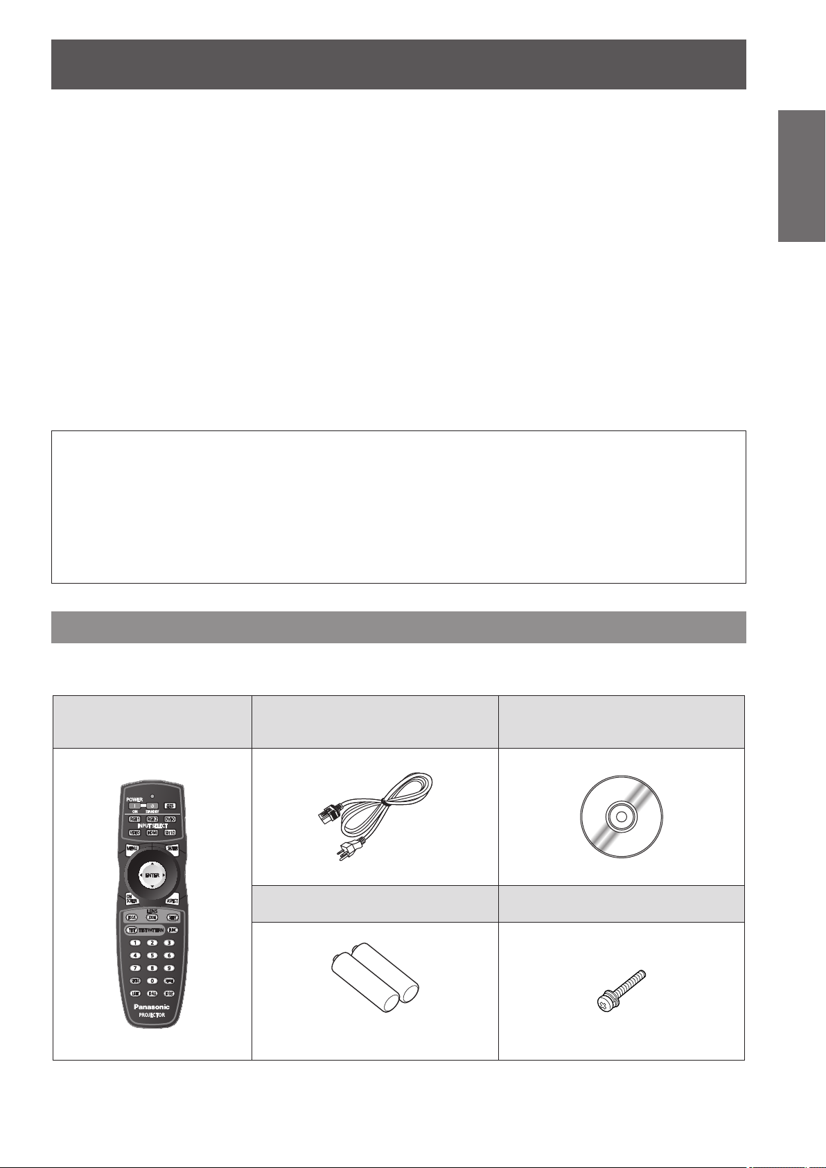
Accessories
Make sure that the following accessories are provided with your projector. Numbers enclosed in < > show the
number of accessories.
Wireless/wired remote control
unit <1>
(N2QAYB000769)
Power cord <1>
(K2CG3YY00035)
AA/R6 battery <2>
CD-ROM <1>
(TXFQB02VKR9)
Lens xing screw <1>
(XYN4+J18FJ)
(For remote control unit)
ENGLISH - 19
Page 20
Precautions for use
Information
Important
Attention
Note
The contents of the supplied CD-ROM are as follows.
zAfter unpacking the projector, discard the power cord cap and packaging material properly.
zFor missing accessories, consult your dealer.
zStore small parts in an appropriate manner, and keep them away from small children.
zThe model numbers of accessories and optional components are subject to change without notice.
Contents of the supplied CD-ROM
■
Instruction/list (PDF) Software
Operating Instructions - Functional
z
Manual
Multi Projector Monitoring & Control
z
Multi Projector Monitoring & Control
z
Software (Windows)
This software allows you to monitor and control
multiple projectors connected to the LAN.
Software Operation Manual
Logo Transfer Software (Windows)
z
Logo Transfer Software Operating
z
Instructions
List of Compatible Projector Models
z
This is a list of projectors that are compatible with
the software contained in the CD-ROM and their
restrictions.
This software allows you to create original
images, such as company logos to be displayed
when projection starts, and transfer them to the
projector.
Software license
z
(GNU GENERAL PUBLIC LICENSE, GNU
LESSER GENERAL PUBLIC LICENSE)
Optional accessories
Optional accessories
(product name)
ET-D75LE6 (Zoom Lens),
ET-D75LE8 (Zoom Lens),
ET-D75LE10 (Zoom Lens),
Projection lens
Ceiling mount bracket ET-PKD510H (for high ceilings), ET-PKD510S (for low ceilings)
Frame ET-PFD510
Replacement lamp unit ET-LAD510 (1 pc), ET-LAD510F (4 pcs)
Replacement lamp unit (for
portrait mode)
Replacement lter unit ET-EMF510
Smoke cut lter ET-SFR510
Upgrade kit ET-UK20 (only for PT-DZ21KU, PT-DS20KU)
ET-D75LE20 (Zoom Lens),
ET-D75LE30 (Zoom Lens),
ET-D75LE40 (Zoom Lens),
ET-D75LE50 (Fixed-Focus Lens)
ET-LAD510P (1 pc), ET-LAD510PF (4 pcs)
Model No.
20 - ENGLISH
Page 21
Start-up display
Start-up display
The initial setting screen is displayed when the projector is switched on for the rst time after purchase as well as
when [ALL USER DATA] ( page 114) in [INITIALIZE] is executed. Set them in accordance with circumstances.
In other occasions, you can change the settings by menu operations.
Note
zWhen the projector is used for the rst time, you may be required to adjust the focus, zoom, and shift to display
the menu screen clearly.
Refer to “Adjusting the focus, zoom, and shift” (
page 52) for details.
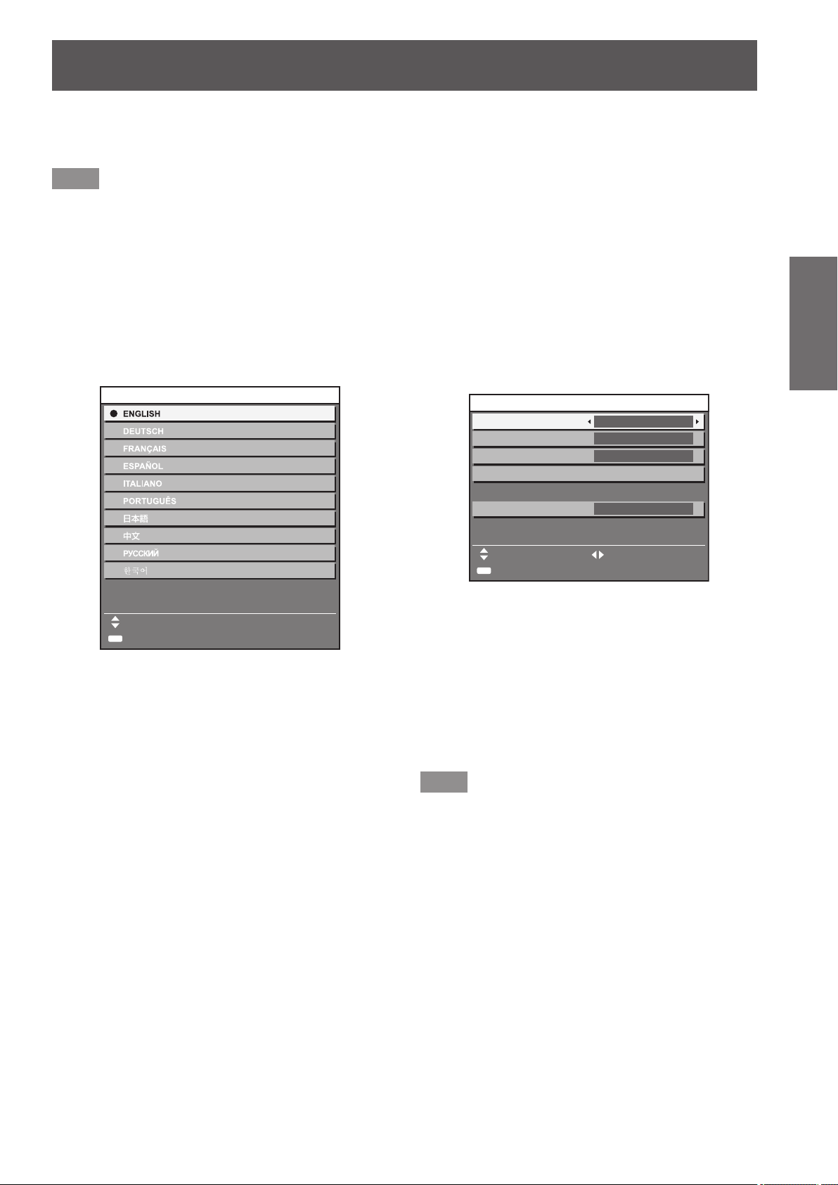
Initial setting (display language)
■
Select the language to show on the screen. ( page 81)
1) Press
to select the desired
language.
INITIAL SETTING
PLEASE SELECT LANGUAGE.
SELECT
ENTER
SET
2) Press the <ENTER> button to proceed
to the initial setting.
Initial setting (projector setup)
■
Set each item.
1) Press
2) Press
INITIAL SETTING
PROJECTION METHOD
COOLING CONDITION
SCREEN FORMAT
SCREEN POSITION
HIGH ALTITUDE MODE
SWITCH TO HIGH ALTITUDE MODE
"ON" IF OVER 1400m(4593Ft).
ENTER
to select an item.
to switch the setting.
FRONT/FLOOR
FLOOR SETTING
MENU SELECT CHANGE
SET
16:10
OFF
Refer to the following page for details of each
item.
[PROJECTION METHOD] ( page 99)
z
[COOLING CONDITION] ( page 100)
z
[SCREEN FORMAT] ( page 90)
z
[SCREEN POSITION] ( page 90)
z
[HIGH ALTITUDE MODE] ( page 100)
z
3) Press the <ENTER> button.
Conrm the setting value to complete the initial
z
setting.
Preparation
Note
zIf you press the <MENU> button in the initial setting
(projector setup) screen, you can go back to the
initial setting (display language) screen.
zYou can set [SCREEN FORMAT] and [SCREEN
POSITION] for PT-DZ21KU and PT-DS20KU.
ENGLISH - 21
Page 22
About your projector
About your projector
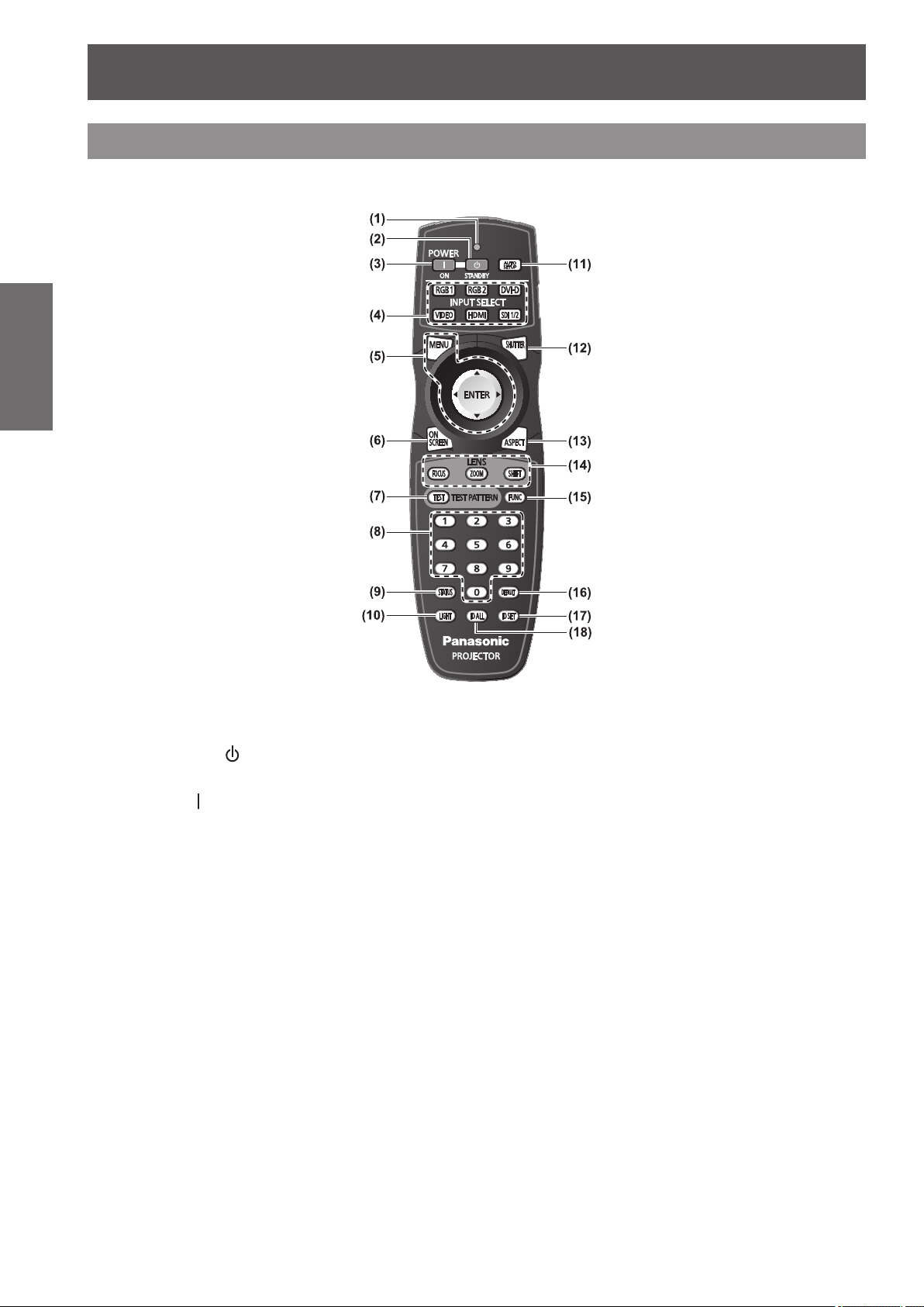
Remote control
Preparation
Front
■
(1) Remote control indicator
Flashes if any button in the remote control is pressed.
(2)
Power standby <
Sets the projector to the standby mode when the <MAIN
POWER> switch on the projector is set to <ON>.
(3)
Power on <
Starts projection when the <MAIN POWER> switch on
the projector is set to <ON> when the power is switched
off (standby mode).
(4) Input selection (<RGB1>, <RGB2>, <DVI-D>,
<VIDEO>, <HDMI>, <SDI 1/2>) buttons
Switches the input signal to project. (
(5) <MENU> button/<ENTER> button/
Used to operate the menu screen. (
(6) <ON SCREEN> button
Switches on (display)/off (not display) the on-screen
display function. (
(7) <TEST> button
Displays the test pattern. (
(8) Number (<0> - <9>) buttons
Used when the system uses multiple projectors.
Used to input ID numbers or passwords.
(9) <STATUS> button
Displays the projector information.
(10) <LIGHT> button
Pressing this button lights up the remote control buttons.
The lights will go off when the remote control operation
goes idle for 10 seconds.
> button
> button
page 58)
page 60)
page 58)
page 61)
buttons
(11) <AUTO SETUP> button
Automatically adjusts the image display position while
projecting the image.
[PROGRESS] is displayed on the screen while the image
is adjusted automatically. (
(12) <SHUTTER> button
Used to temporarily turn off the image. (
(13) <ASPECT> button
Switches the aspect ratio of the image. (
(14) Lens (<FOCUS>, <ZOOM>, <SHIFT>) buttons
Adjusts the projection lens. (
(15) <FUNC> button
You can assign a frequently used operation to a shortcut
button. (
(16) <DEFAULT> button
Restores the contents of the sub-menu to factory default.
(
(17) <ID SET> button
Sets the ID number of the remote control when the
system uses multiple projectors.
(
(18) <ID ALL> button
Simultaneously controls all the projectors with one
remote control when the system uses multiple projectors.
(
page 62)
page 27)
page 27)
page 59)
page 59)
pages 50, 52)
page 58)
page 60)
22 - ENGLISH
Page 23
About your projector
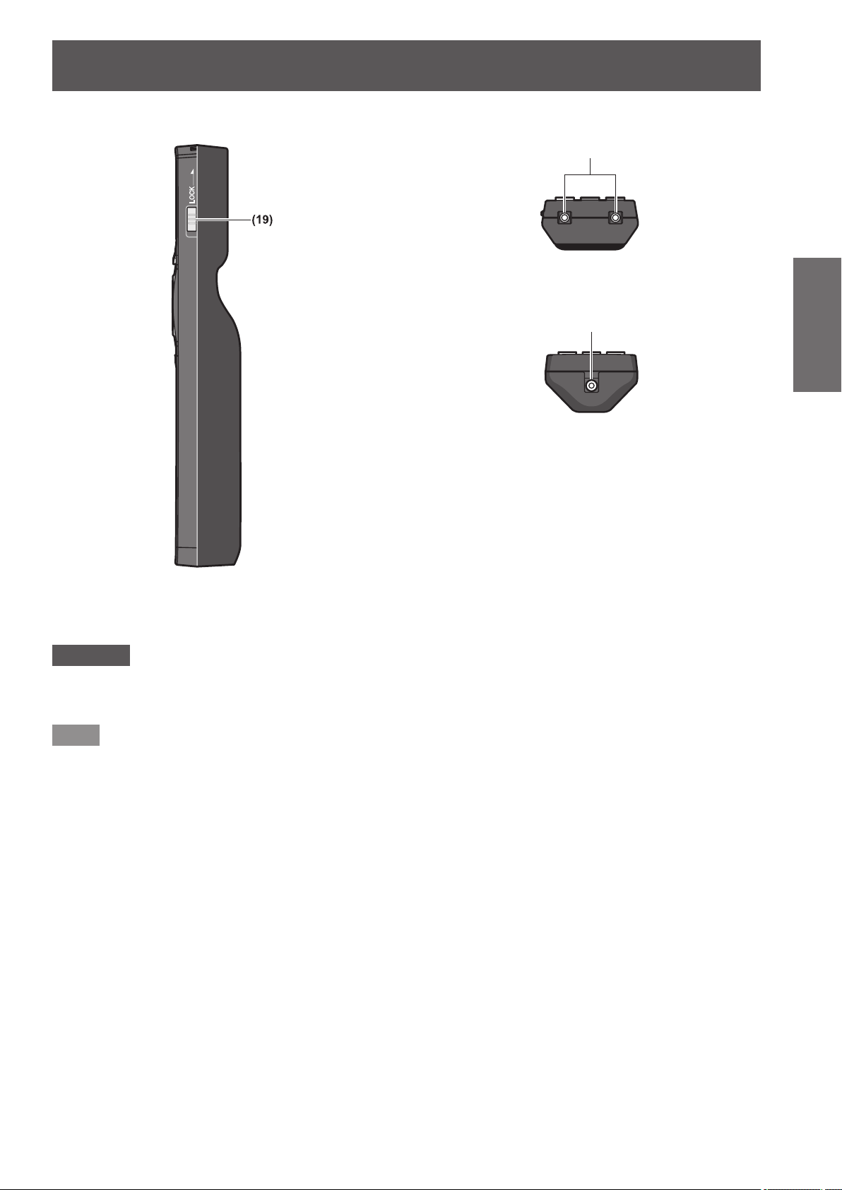
Remote control signal transmitter
Remote control wired terminal
Side
■
Top
■
Bottom
■
( page 27)
Preparation
(19) <LOCK> button
Used to prevent unintended operation by careless pressing of the buttons and prevent draining the remote control batteries.
Attention
zDo not drop the remote control.
zAvoid contact with liquids or moisture.
zDo not attempt to modify or disassemble the remote control.
Note
zThe remote control can be used within a distance of about 30 m (98'5") if pointed directly at the remote control
receiver. The remote control can control at angles of up to ±15° vertically and ±30° horizontally, but the effective
control range may be reduced.
zIf there are any obstacles between the remote control and the remote control signal receiver, the remote
control may not operate properly.
zThe signal will be reected off the screen. However, the operating range may be limited due to light reection
loss because of the screen material.
zIf the remote control signal receiver directly receives strong light, such as uorescent light, the remote control
may not operate properly. Use it in a place distant from the light source.
zThe power indicator <ON (G)/STANDBY (R)> will ash if the projector receives a remote control signal.
ENGLISH - 23
Page 24
About your projector
Projector body
Preparation
Front
■
■Rear
Side
■
)URQW
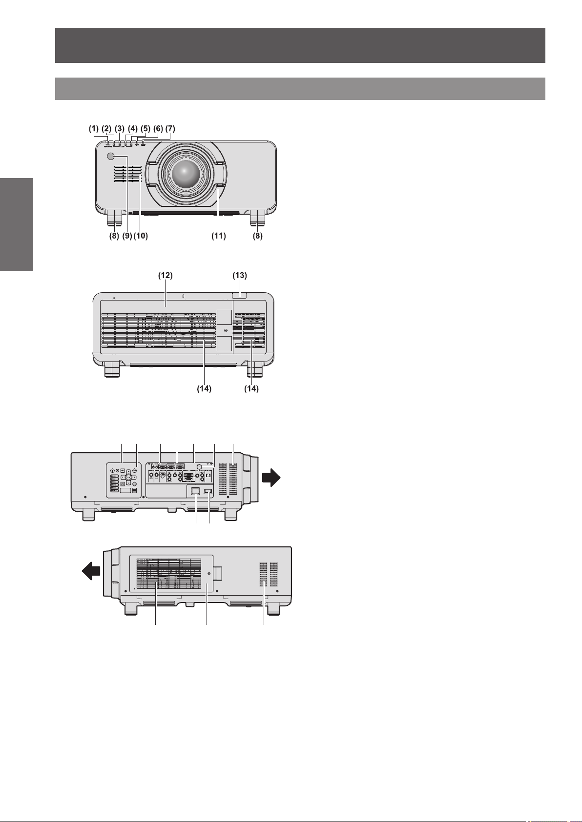
(1) Power indicator <ON (G)/STANDBY (R)>
The power indicator displays power status.
(2) Lamp indicator <LAMP1>
Displays the status of lamp 1.
(3) Lamp indicator <LAMP2>
Displays the status of lamp 2.
(4) Lamp indicator <LAMP3>
Displays the status of lamp 3.
(5) Lamp indicator <LAMP4>
Displays the status of lamp 4.
(6) Temperature indicator <TEMP>
Displays the internal temperature status.
(7) Filter indicator <FILTER>
Displays the status of the air lter unit.
(8) Adjustable feet
Adjusts the projection angle.
(9) Remote control signal receiver (front)
(10) Air intake port
(11) Projection lens cover
(12) Lamp unit cover (
(13) Remote control signal receiver (rear)
(14) Air exhaust port
(15) Control panel and connecting terminals lights
(16) Control panel (
(17) Connecting terminals (
(18) Security slot
This security slot is compatible with the Kensington
security cables.
(19) <AC IN> terminal
Connect the supplied power cord.
(20) <MAIN POWER> switch
Turns on/off the main power.
(21) Air lter cover
The air lter unit is inside. (
page 25)
page 148)
page 26)
page 144)
)URQW
24 - ENGLISH
Page 25
About your projector
■Bottom
)URQW
Control panel
■
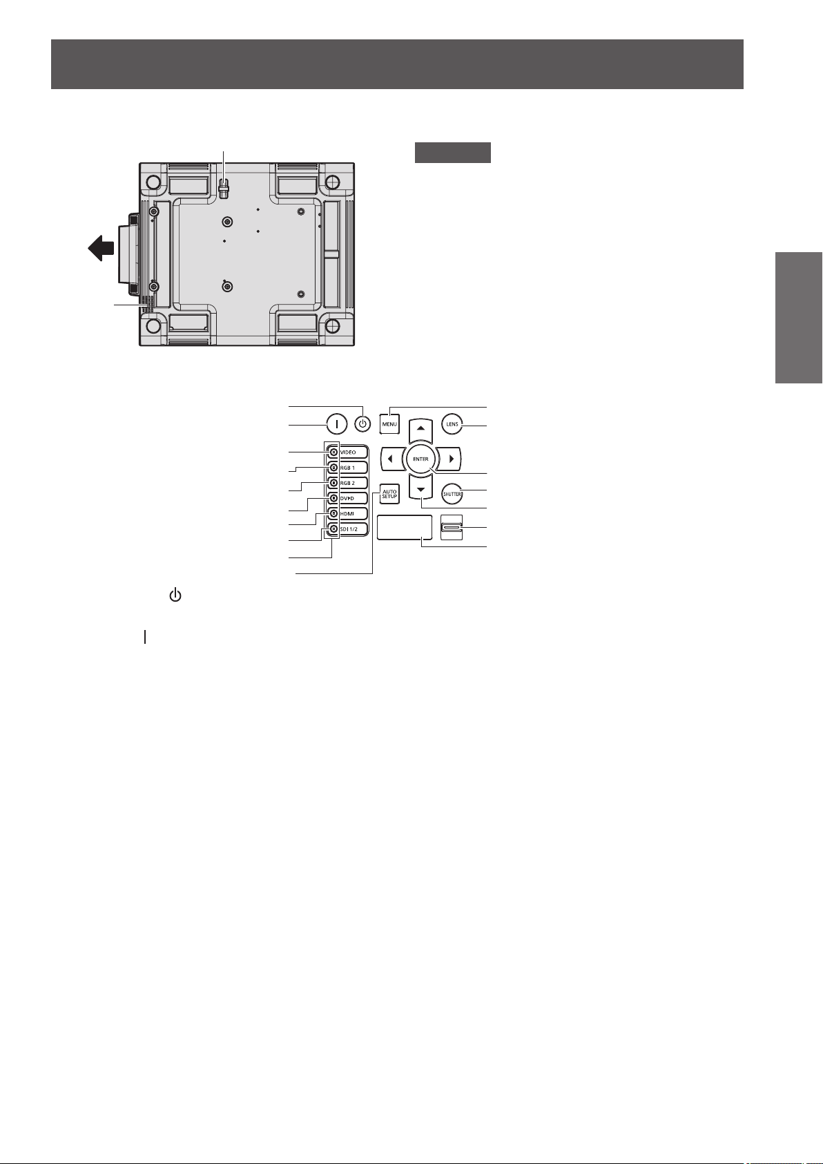
(1)
(2)
(3)
(4)
(5)
(6)
(7)
(8)
(9)
(10)
(1)
Power standby <
Sets the projector to the standby mode when the <MAIN
POWER> switch on the projector is set to <ON>.
(2)
Power on <
Starts projection when the <MAIN POWER> switch on the
projector is set to <ON> when the power is switched off
(standby mode).
(3) <VIDEO> button
Switches to VIDEO input.
(4) <RGB1> button
Switches to RGB1 input.
(5) <RGB2> button
Switches to RGB2 input.
(6) <DVI-D> button
Switches to DVI-D input.
(7) <HDMI> button
Switches to HDMI input.
(8) <SDI 1/2> button
Switches to SDI input.
(Only for PT-DZ21KU, PT-DS20KU)
(9) Input selection terminal indicator
Indicator which shows the selected input terminal. This
lights up when an image signal is being input in the
selected input terminal, and ashes when there is no
image signal.
(10) <AUTO SETUP> button
Automatically adjusts the image display position while
projecting the image.
[PROGRESS] is displayed on the screen while the image
is adjusted automatically. (
> button
> button
page 59)
(22) Burglar hook port
You can attach a commercial burglar prevention cable.
Attention
zKeep your hands and other objects away from the
air exhaust port.
Keep your hands and face away.
Do not insert your ngers.
Keep heat-sensitive objects away.
Heated air from the air outlet port can cause bums,
injury, or deformations.
zDo not block the ventilation ports (intake and
exhaust) of the projector.
(11)
(12)
(13)
(14)
(15)
(16)
(17)
(11) <MENU> button
Displays the main menu.
Returns to the previous menu when the menu is displayed.
page 61)
(
If you press the <MENU> button on the control panel for
at least three seconds while the on-screen indication is off,
the on-screen display is turned on.
(12) <LENS> button
Adjusts the focus, zoom, and shift (position) of the lens.
(13) <ENTER> button
Determines and executes an item in the menu screen.
(14) <SHUTTER> button
Used to temporarily turn off the image. (
(15)
Use to select items in the menu screen, change settings,
and adjust levels.
It is also used to enter [SECURITY] passwords.
(16) <LIGHT> switch
Light switch for the connecting terminals and the control
panel.
(17) Self-diagnosis display
Automatically shows errors and warnings, and their details.
(
buttons
page 153)
page 58)
Preparation
ENGLISH - 25
Page 26
About your projector
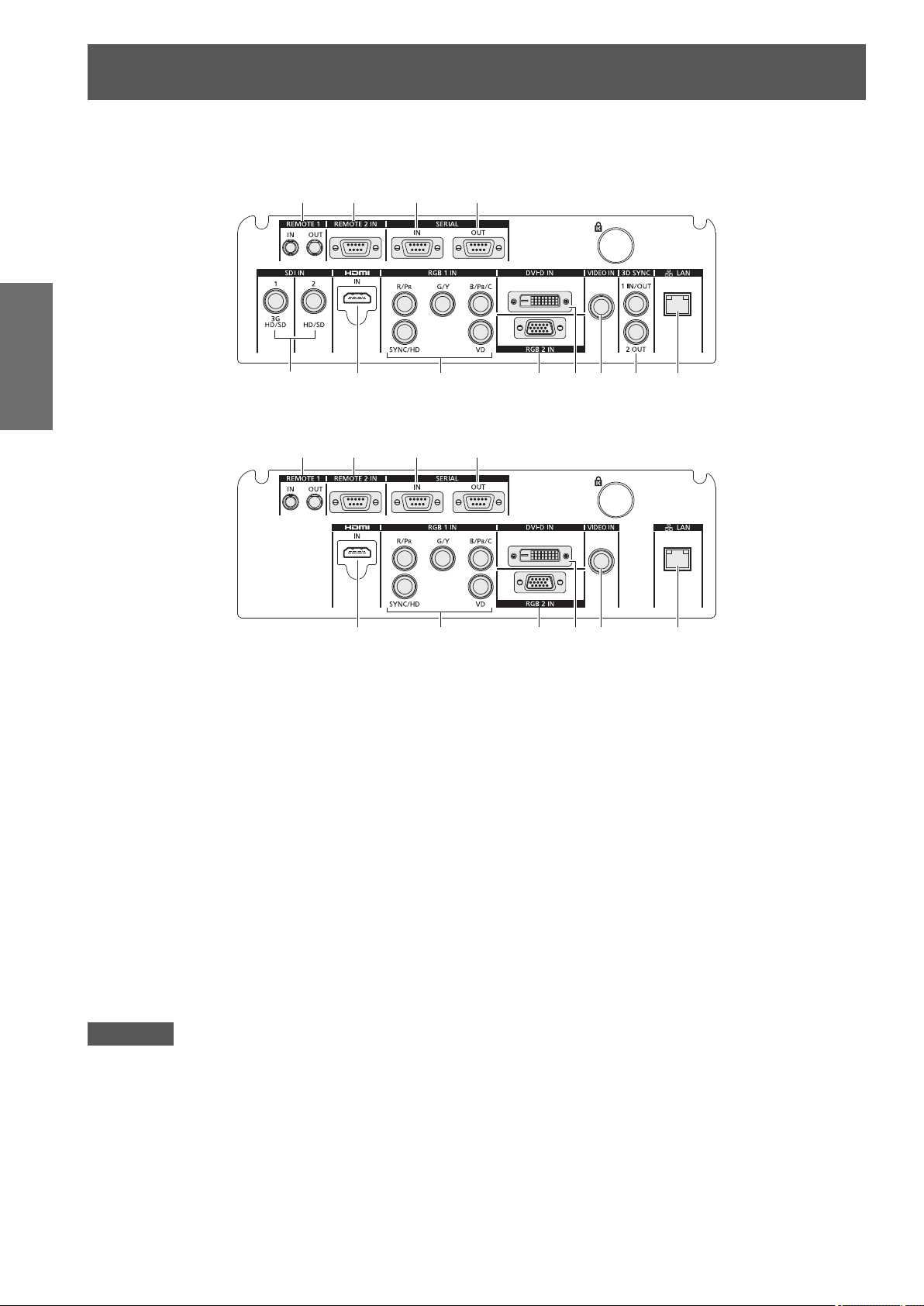
For PT-DZ21KU, PT-DS20KU
z
Preparation
For PT-DW17KU
z
Connecting terminals
■
(1) (2) (3) (4)
(5) (6) (7) (8) (9) (10) (11) (12)
(1) (2) (3) (4)
(6) (7) (8) (9) (10) (12)
(1) <REMOTE 1 IN> terminal / <REMOTE 1 OUT> terminal
These are the terminals to connect the remote control for
serial control when the system uses multiple projectors.
(2) <REMOTE 2 IN> terminal
This is a terminal to remotely control the projector using
the external control circuit.
(3) <SERIAL IN> terminal
This is a RS-232C compatible terminal to externally control
the projector by connecting a computer.
(4) <SERIAL OUT> terminal
This is a terminal to output the signal connected to the
serial input terminal.
(5) <SDI IN 1> terminal / <SDI IN 2> terminal
This is a terminal to input the SDI signal.
(Only for PT-DZ21KU, PT-DS20KU)
(6) <HDMI IN> terminal
This is a terminal to input the HDMI signal.
(7) <RGB 1 IN> (<R/P
<VD>) terminal
This is a terminal to input RGB signals or the YC
and Y/C signals.
YP
BPR
(8) <RGB 2 IN> terminal
This is a terminal to input RGB signals or YC
signals.
(9) <DVI-D IN> terminal
This is a terminal to input DVI-D signals.
(10) <VIDEO IN> terminal
This is a terminal to input video signals.
(11) <3D SYNC 1 IN/OUT> terminal / <3D SYNC 2 OUT>
terminal
This is a terminal to input or output control signals when
using the projector in 3D systems.
(Only for PT-DZ21KU, PT-DS20KU)
(12) <LAN> terminal
This is a terminal to connect to the network.
Used for control and monitoring. Image input through
network connections is not possible.
>, <G/Y>, <B/PB/C>, <SYNC/HD>,
R
BCR
Attention
zWhen a LAN cable is directly connected to the projector, the network connection must be made indoors.
/
BCR
/YPBPR
26 - ENGLISH
Page 27
Using the remote control
Using the remote control
Inserting and removing the batteries
1) Open the cover.
(ii)
(i)
2) Insert the batteries and close the cover
(insert the
When removing the batteries, perform the steps
z
in reverse order.
side rst).
Setting Remote control ID numbers
When you use the system with multiple projectors,
you can operate all the projectors simultaneously or
each projector individually using single remote control,
if a unique ID number is assigned to each projector.
After setting the ID number of the projector, set same
ID number on the remote control.
The ID number of the projector is set to [ALL] as
the factory default. When using a single projector,
press the <ID ALL> button on the remote control.
Also, you can perform control operations if you
push the <ID ALL> button on the remote control
even if you do not know the projector ID.
How to set
■
zThe ID number set on the remote control will
be stored unless it is set again. However, it will
be erased if the remote control is left with dead
batteries. Set the same ID number again when the
batteries are replaced.
Note
zSet the ID number of the projector from the
[PROJECTOR SETUP] menu → [PROJECTOR ID]
page 99).
(
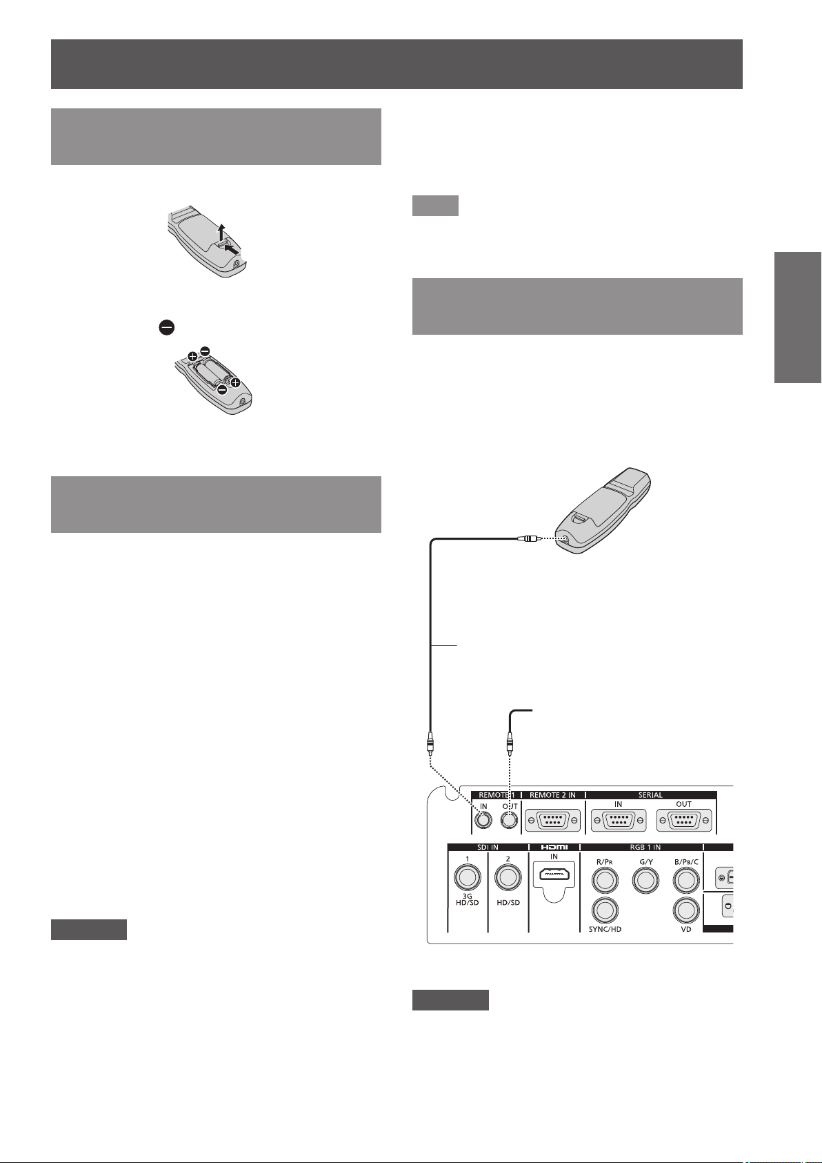
Connecting to the projector with a cable
When you use the system with multiple projectors,
congure the units as in the following gure. Use a
commercial M3 stereo mini jack cable and connect
the other devices to the <REMOTE 1 IN>/<REMOTE
1 OUT> terminals of the projector.
The remote control is effective even in places where
an obstacle stands in the light path or where devices
are susceptible to outside light.
Remote control
Connects to the remote
control wired terminal
M3 stereo mini jack cable
(commercially available)
Connecting to a
second projector
Preparation
1) Press the <ID SET> button on the
remote control.
2) Within ve seconds, press the twodigit ID number set on the projector
using the number (<0> - <9>) buttons.
If you press the <ID ALL> button, you can
z
operate the projectors regardless of the setting
of the projector’s ID number.
Attention
zSince setting of the ID number on the remote
control can be performed even without the projector,
do not press the <ID SET> button carelessly. If the
number (<0> - <9>) buttons are not pressed within
ve seconds after the <ID SET> button is pressed,
the ID number returns to its original value before
pressing the <ID SET> button.
Connecting terminals
Attention
zUse a cable that is 15 m (49'2") or shorter, with 2
core shield. The remote control may not operate
when the length of the cable exceeds 15 m (49'2")
or when the shielding of the cable is inadequate.
ENGLISH - 27
Page 28
Setting up
Setting up
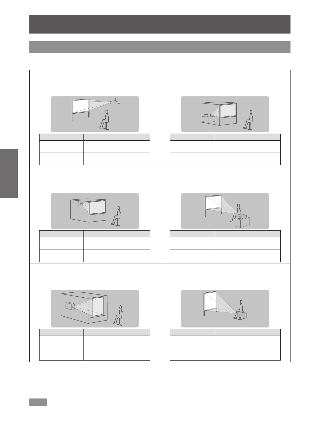
Projection method
You can use the projector with any of the following six projection methods. Select the appropriate method
depending on the environment.
Mounting on the ceiling and
■
projecting forward
[PROJECTION
Getting Started
Mounting on the ceiling and
■
projecting from rear
(Using the translucent screen)
Menu item
METHOD]
[COOLING
CONDITION]
*1
Method
[FRONT/CEILING]
[CEILING SETTING]
Setting on a desk/oor and
■
projecting from rear
(Using the translucent screen)
Menu item
[PROJECTION
METHOD]
[COOLING
CONDITION]
Setting on a desk/oor and
■
*1
Method
[REAR/FLOOR]
[FLOOR SETTING]
projecting forward
Menu item
[PROJECTION
METHOD]
[COOLING
CONDITION]
Portrait setting and projecting
■
from rear
(Using the translucent screen)
Menu item
[PROJECTION
METHOD]
[COOLING
CONDITION]
*1: For menu item details, see the [PROJECTOR SETUP] menu → [PROJECTION METHOD] ( page 99) and [COOLING
CONDITION] (
*2: For portrait setting, use the optional accessory replacement lamp unit (for portrait mode) (Model No.: ET-LAD510P (1 pc),
ET-LAD510PF (4 pcs)).
*3: Using the optional accessory replacement lamp unit (for portrait mode) (Model No.: ET-LAD510P (1 pc), ET-LAD510PF (4 pcs))
will set the cooling condition to [PORTRAIT SETTING].
*1
*2
*1
page 100).
Method
[REAR/CEILING]
[CEILING SETTING]
Method
[REAR/FLOOR]
[PORTRAIT SETTING]
Menu item
[PROJECTION
METHOD]
[COOLING
CONDITION]
Portrait setting and projecting
■
forward
Menu item
[PROJECTION
METHOD]
*3
[COOLING
CONDITION]
*2
*1
*1
[PORTRAIT SETTING]
Method
[FRONT/FLOOR]
[FLOOR SETTING]
Method
[FRONT/FLOOR]
*3
Note
zDuring portrait setting, the on-screen menu will be displayed horizontally.
28 - ENGLISH
Page 29
Setting up
Projection screen
Parts for ceiling mount (optional)
You can install the projector on the ceiling using the optional ceiling mount bracket (Model No.: ET-PKD510H (for
high ceilings), or ET-PKD510S (for low ceilings).
zUse only the ceiling mount brackets specied for this projector.
zRefer to the installation manual for the ceiling mount bracket when installing the bracket and the projector.
Attention
zTo ensure projector performance and security, installation of the ceiling mount bracket must be carried out by
your dealer or a qualied technician.
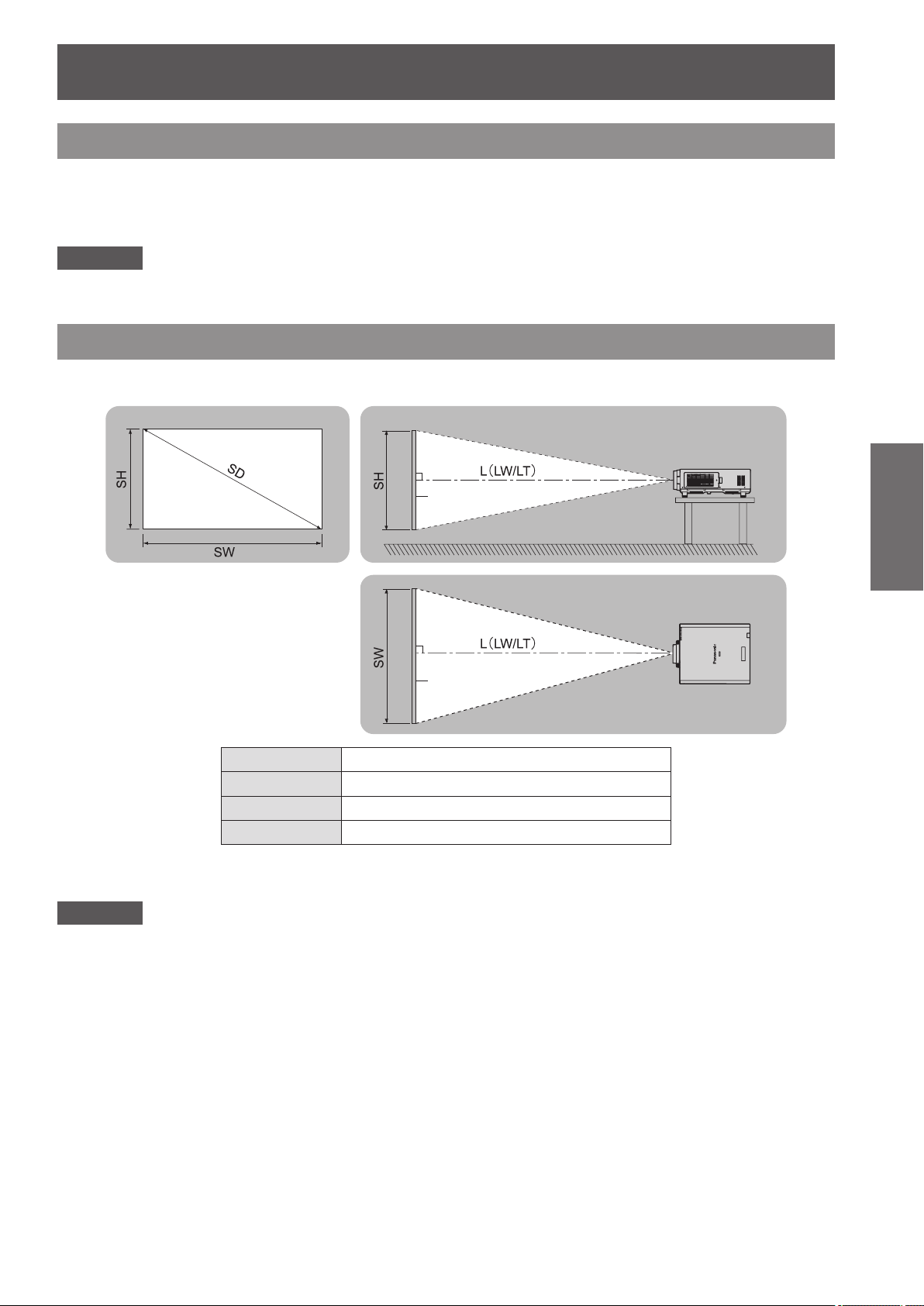
Screen size and throw distance
Refer to the following gures and table describing projection distances to install the projector. Image size and
image position can be adjusted in accordance with the screen size and screen position.
Screen
Screen
L (LW/LT)
*1: LW: Minimum projection distance when the Zoom Lens is used
Attention
zBefore installing, read “Precautions for use” (
zDo not use the projector and the high-powered laser equipment in the same room.
Hitting of a laser beam on to the lens can damage the DLP chips.
*1
SH Image height (m)
SW Image width (m)
SD Image diagonal size (m)
LT: Maximum projection distance when the Zoom Lens is used
Projection distance (m)
pages 15 to 20).
Getting Started
ENGLISH - 29
Page 30
Setting up
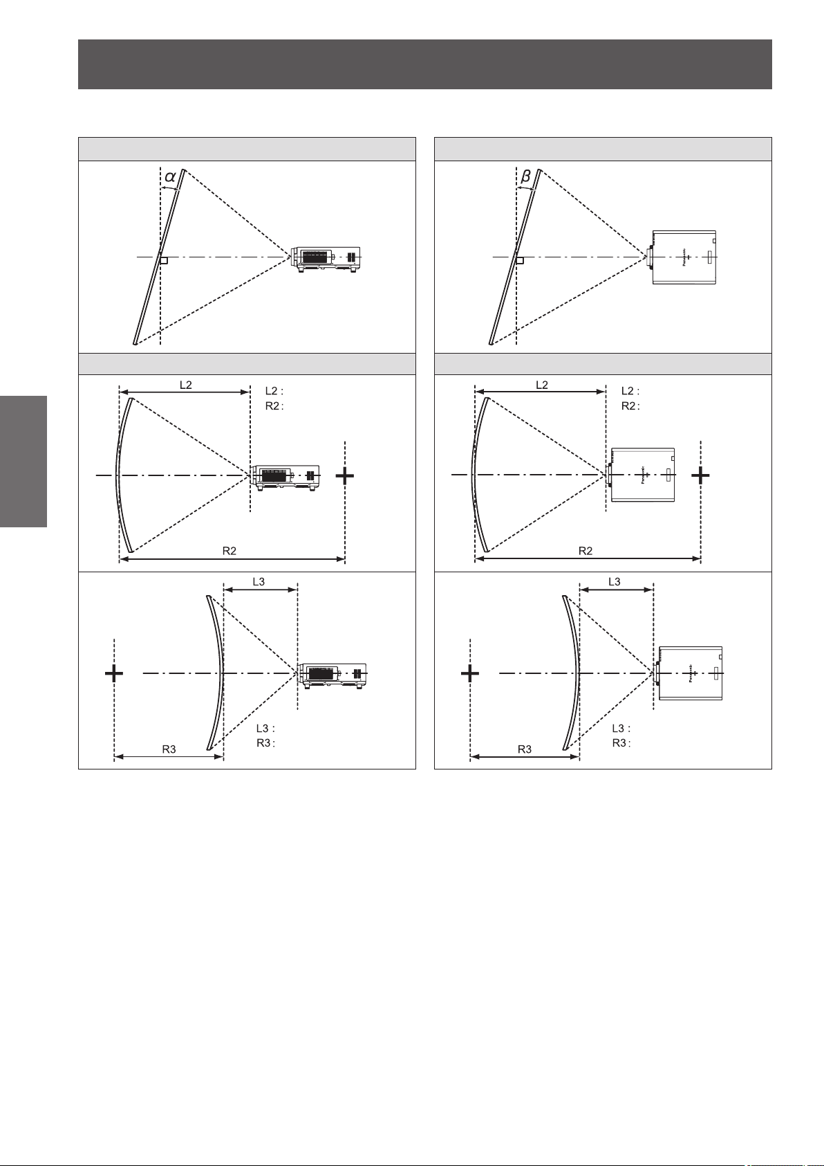
[GEOMETRY] projection range (PT-DZ21KU and PT-DS20KU only)
■
[VERTICAL KEYSTONE] (viewed from the side) [HORIZONTAL KEYSTONE] (viewed from above)
6FUHHQ 6FUHHQ
Vertical arc correction (viewed from the side) Horizontal arc correction (viewed from above)
Getting Started
$UFFHQWHU
6FUHHQ
6FUHHQ
3URMHFWLRQGLVWDQFH
$UFUDGLXV
3URMHFWLRQGLVWDQFH
$UFUDGLXV
3URMHFWLRQGLVWDQFH
$UFUDGLXV
6FUHHQ
$UFFHQWHU
6FUHHQ
3URMHFWLRQGLVWDQFH
$UFUDGLXV
30 - ENGLISH
Page 31

Setting up
Standard
z
Only for [KEYSTONE] [KEYSTONE] and [CURVED] used together Only for [CURVED]
Projection lens
Model No.
ET-D75LE1 ±40 ±15 ±20 ±15 1.0 2.3 0.6 1.3
ET-D75LE2 ±40 ±15 ±20 ±15 0.8 1.6 0.5 0.9
ET-D75LE3 ±40 ±15 ±20 ±15 0.6 1.1 0.3 0.6
ET-D75LE4 ±40 ±15 ±20 ±15 0.4 0.7 0.2 0.4
ET-D75LE5 ±22 ±15 ±8 ±8 2.0 4.9 1.2 2.9
ET-D75LE6 ±28 ±15 ±10 ±10 1.6 3.9 0.9 2.3
ET-D75LE8 ±40 ±15 ±20 ±15 0.2 0.4 0.2 0.3
ET-D75LE10 ±40 ±15 ±20 ±15 1.1 2.6 0.6 1.5
ET-D75LE20 ±40 ±15 ±20 ±15 0.9 1.7 0.5 1.0
ET-D75LE30 ±40 ±15 ±20 ±15 0.6 1.2 0.4 0.7
ET-D75LE40 ±40 ±15 ±20 ±15 0.4 0.7 0.2 0.4
ET-D75LE50 ±22 ±15 ±8 ±8 2.0 4.9 1.2 2.9
Vertical
trapezoidal
distortion
correction
angle α (°)
Horizontal
trapezoidal
distortion
correction
angle β (°)
Vertical
trapezoidal
distortion
correction
angle α (°)
Horizontal
trapezoidal
distortion
correction
angle β (°)
Minimum
value of R2/
L2
Minimum
value of R3/
L3
Minimum
value of R2/
L2
Minimum
value of R3/
L3
Using optional upgrade kit (ET-UK20)
z
Only [KEYSTONE]
Projection lens
Model No.
ET-D75LE1 ±40 ±40 ±20 ±15 0.8 1.8 0.5 1.0
ET-D75LE2 ±40 ±40 ±20 ±15 0.6 1.2 0.4 0.7
ET-D75LE3 ±45 ±40 ±20 ±15 0.4 0.8 0.3 0.5
ET-D75LE4 ±45 ±40 ±20 ±15 0.3 0.5 0.2 0.3
ET-D75LE5 ±22 ±15 ±8 ±8 1.5 3.7 0.9 2.2
ET-D75LE6 ±28 ±15 ±10 ±10 1.2 3.0 0.7 1.7
ET-D75LE8 ±45 ±40 ±20 ±15 0.2 0.3 0.1 0.2
ET-D75LE10 ±40 ±40 ±20 ±15 0.9 2.0 0.5 1.1
ET-D75LE20 ±40 ±40 ±20 ±15 0.7 1.3 0.4 0.7
ET-D75LE30 ±45 ±40 ±20 ±15 0.5 0.9 0.3 0.5
ET-D75LE40 ±45 ±40 ±20 ±15 0.3 0.5 0.2 0.3
ET-D75LE50 ±22 ±15 ±8 ±8 1.5 3.7 0.9 2.2
*1: Cannot correct [VERTICAL KEYSTONE] and [HORIZONTAL KEYSTONE] if the total exceeds 55° when used at the same time.
Vertical
trapezoidal
distortion
correction
angle α (°)
*1
Horizontal
trapezoidal
distortion
correction
angle β (°)
[KEYSTONE] and [CURVED] used together Only for [CURVED]
Vertical
trapezoidal
distortion
correction
angle α (°)
Horizontal
trapezoidal
distortion
correction
angle β (°)
Minimum
value of R2/
L2
Minimum
value of R3/
L3
Minimum
value of R2/
L2
Minimum
value of R3/
L3
Note
zWhen [GEOMETRY] is used, the focus of the entire screen may be lost as correction increases.
zMake the curved screen a circular arc shape with one part of a perfect circle removed.
zAdjustment range of the [GEOMETRY] items may not match above due to the projection lens. Use this
projector within the projection range, otherwise the correction does not work.
Getting Started
ENGLISH - 31
Page 32

Setting up
Projection distance of each projection lens (for PT-DZ21KU)
■
When the screen aspect is 16:10 (unit: m)
z
Projection lens Model No. ET-D75LE1 ET-D75LE2 ET-D75LE3 ET-D75LE4 ET-D75LE8 ET-D75LE6
Throw ratio*
Screen size Projection distance (L)
Screen
2
diagonal*
(SD)
1.78 (70")
2.03 (80")
2.29 (90")
2.54 (100")
3.05 (120")
Getting Started
3.81 (150")
5.08 (200")
6.35 (250")
7.62 (300")
8.89 (350")
10.16 (400")
12.70 (500")
15.24 (600")
Lens type Zoom Lens
1
Height
(SH)
0.942 1.508 2.01 2.69 2.72 4.10 4.11 6.90 6.91 11.06 10.78 20.56 1.35 1.62
1.077 1.723 2.31 3.09 3.12 4.70 4.71 7.90 7.91 12.66 12.37 23.55 1.55 1.86
1.212 1.939 2.61 3.49 3.52 5.30 5.31 8.91 8.91 14.25 13.97 26.54 1.76 2.10
1.346 2.154 2.91 3.89 3.92 5.90 5.91 9.91 9.91 15.85 15.57 29.53 1.96 2.34
1.615 2.585 3.51 4.68 4.73 7.10 7.11 11.91 11.92 19.04 18.76 35.50 2.36 2.82
2.019 3.231 4.40 5.88 5.93 8.90 8.91 14.92 14.93 23.82 23.54 44.47 2.96 3.55
2.692 4.308 5.89 7.87 7.93 11.91 11.92 19.94 19.95 31.80 31.52 59.41 3.97 4.75
3.365 5.385 7.39 9.87 9.93 14.91 14.92 24.95 24.96 39.77 39.49 74.36 4.98 5.96
4.039 6.462 8.88 11.86 11.93 17.91 17.92 29.97 29.98 47.75 47.47 89.30 5.99 7.17
4.712 7.539 10.37 13.86 13.93 20.91 20.92 34.98 34.99 55.72 55.44 104.24 6.99 8.37
5.385 8.616 11.86 15.85 15.94 23.92 23.93 40.00 40.01 63.70 63.42 119.19 8.00 9.58
6.731 10.770 14.85 19.84 19.94 29.92 29.93 50.03 50.04 79.65 79.37 149.08 10.01 11.99
8.077 12.923 17.83 23.82 23.94 35.93 35.94 60.06 60.07 95.60 95.32 178.96 12.03 14.40
Width
(SW)
1.4 to 1.8:1 1.8 to 2.8:1 2.8 to 4.6:1 4.6 to 7.4:1 7.3 to 13.8:1 0.9 to 1.1:1
Min.
(LW)
Max.
(LT)
Min.
(LW)
Max.
(LT)
Min.
(LW)
Max.
(LT)
Min.
(LW)
Max.
(LT)
Min.
(LW)
Max.
(LT)
Min.
(LW)
Max.
(LT)
Lens type Zoom Lens Fixed-Focus Lens
Projection lens Model No. ET-D75LE10 ET-D75LE20 ET-D75LE30 ET-D75LE40 ET-D75LE5 ET-D75LE50
Throw ratio*
Screen size Projection distance (L)
Screen
diagonal*
1.78 (70")
2.03 (80")
2.29 (90")
2.54 (100")
3.05 (120")
3.81 (150")
5.08 (200")
6.35 (250")
7.62 (300")
8.89 (350")
10.16 (400")
12.70 (500")
15.24 (600")
*1: The throw ratio is based on the value during projection onto a 3.81-m (150") screen size.
*2: The screen size unit is inches.
Height
2
(SD)
(SH)
0.942 1.508 1.90 2.46 2.46 3.58 3.56 6.94 6.87 11.04 0.99 1.01
1.077 1.723 2.19 2.83 2.82 4.11 4.08 7.96 7.88 12.65 1.15 1.16
1.212 1.939 2.47 3.20 3.19 4.64 4.61 8.98 8.88 14.25 1.30 1.32
1.346 2.154 2.76 3.56 3.55 5.17 5.13 9.99 9.88 15.85 1.45 1.47
1.615 2.585 3.32 4.30 4.28 6.22 6.18 12.03 11.89 19.05 1.76 1.78
2.019 3.231 4.18 5.40 5.37 7.81 7.75 15.08 14.90 23.85 2.22 2.24
2.692 4.308 5.60 7.24 7.19 10.45 10.38 20.16 19.92 31.86 2.99 3.01
3.365 5.385 7.02 9.07 9.00 13.09 13.00 25.25 24.95 39.86 3.76 3.78
4.039 6.462 8.44 10.91 10.82 15.73 15.62 30.34 29.97 47.87 4.53 4.56
4.712 7.539 9.86 12.74 12.64 18.37 18.24 35.42 34.99 55.87
5.385 8.616 11.28 14.58 14.46 21.01 20.86 40.51 40.01 63.87
6.731 10.770 14.12 18.25 18.09 26.29 26.11 50.68 50.05 79.88
8.077 12.923 16.96 21.92 21.73 31.58 31.35 60.85 60.09 95.89
1
Width
(SW)
1.3 to 1.7:1 1.7 to 2.4:1 2.4 to 4.7:1 4.6 to 7.4:1 0.7:1 0.7:1
Min.
(LW)
Max.
(LT)
Min.
(LW)
Max.
(LT)
Min.
(LW)
Max.
(LT)
Min.
(LW)
Max.
(LT)
Fixed Fixed
Note
zA ±5% error in listed projection distances may occur.
zWhen [GEOMETRY] is used, distance is corrected to become smaller than the specied screen size.
32 - ENGLISH
Page 33

Setting up
When the screen aspect is 16:9 (unit: m)
z
Lens type Zoom Lens
Projection lens Model No. ET-D75LE1 ET-D75LE2 ET-D75LE3 ET-D75LE4 ET-D75LE8 ET-D75LE6
Throw ratio*
Screen size Projection distance (L)
Screen
diagonal*
1.78 (70")
2.03 (80")
2.29 (90")
2.54 (100")
3.05 (120")
3.81 (150")
5.08 (200")
6.35 (250")
7.62 (300")
8.89 (350")
10.16 (400")
12.70 (500")
15.24 (600")
Height
2
(SD)
(SH)
0.872 1.550 2.07 2.77 2.80 4.21 4.23 7.09 7.10 11.37 11.09 21.14 1.39 1.66
0.996 1.771 2.38 3.18 3.21 4.83 4.84 8.13 8.13 13.01 12.73 24.21 1.60 1.91
1.121 1.992 2.68 3.59 3.62 5.45 5.46 9.16 9.16 14.65 14.37 27.29 1.81 2.16
1.245 2.214 2.99 4.00 4.04 6.07 6.08 10.19 10.19 16.29 16.01 30.36 2.01 2.41
1.494 2.657 3.60 4.82 4.86 7.30 7.31 12.25 12.26 19.57 19.29 36.50 2.43 2.90
1.868 3.321 4.53 6.05 6.09 9.15 9.16 15.34 15.35 24.49 24.21 45.72 3.05 3.65
2.491 4.428 6.06 8.10 8.15 12.24 12.25 20.50 20.50 32.69 32.40 61.08 4.08 4.89
3.113 5.535 7.59 10.15 10.21 15.33 15.34 25.65 25.66 40.88 40.60 76.44 5.12 6.13
3.736 6.641 9.13 12.19 12.27 18.41 18.42 30.81 30.81 49.08 48.80 91.79 6.15 7.37
4.358 7.748 10.66 14.24 14.32 21.50 21.51 35.96 35.97 57.28 57.00 107.15 7.19 8.61
4.981 8.855 12.19 16.29 16.38 24.58 24.60 41.12 41.12 65.47 65.19 122.51 8.22 9.85
6.226 11.069 15.26 20.39 20.50 30.76 30.77 51.42 51.43 81.87 81.59 153.23 10.29 12.33
7.472 13.283 18.33 24.49 24.61 36.93 36.94 61.73 61.74 98.26 97.98 183.95 12.36 14.81
1
Width
(SW)
1.4 to 1.8:1 1.8 to 2.8:1 2.8 to 4.6:1 4.6 to 7.4:1 7.3 to 13.8:1 0.9 to 1.1:1
Min.
(LW)
Max.
(LT)
Min.
(LW)
Max.
(LT)
Min.
(LW)
Max.
(LT)
Min.
(LW)
Max.
(LT)
Min.
(LW)
Max.
(LT)
Min.
(LW)
Max.
(LT)
Getting Started
Lens type Zoom Lens Fixed-Focus Lens
Projection lens Model No. ET-D75LE10 ET-D75LE20 ET-D75LE30 ET-D75LE40 ET-D75LE5 ET-D75LE50
Throw ratio*
Screen size Projection distance (L)
Screen
diagonal*
1.78 (70")
2.03 (80")
2.29 (90")
2.54 (100")
3.05 (120")
3.81 (150")
5.08 (200")
6.35 (250")
7.62 (300")
8.89 (350")
10.16 (400")
12.70 (500")
15.24 (600")
*1: The throw ratio is based on the value during projection onto a 3.81-m (150") screen size.
*2: The screen size unit is inches.
(SD)
Height
2
(SH)
0.872 1.550 1.96 2.53 2.53 3.68 3.66 7.14 7.07 11.36 1.02 1.04
0.996 1.771 2.25 2.91 2.91 4.23 4.20 8.19 8.10 13.00 1.18 1.20
1.121 1.992 2.54 3.29 3.28 4.77 4.74 9.23 9.13 14.65 1.34 1.36
1.245 2.214 2.83 3.67 3.65 5.31 5.28 10.28 10.16 16.29 1.50 1.51
1.494 2.657 3.42 4.42 4.40 6.40 6.35 12.37 12.23 19.58 1.81 1.83
1.868 3.321 4.29 5.55 5.52 8.03 7.97 15.50 15.32 24.52 2.29 2.31
2.491 4.428 5.75 7.44 7.39 10.74 10.67 20.73 20.48 32.75 3.08 3.10
3.113 5.535 7.21 9.33 9.26 13.46 13.36 25.96 25.64 40.97 3.87 3.89
3.736 6.641 8.67 11.21 11.13 16.17 16.06 31.18 30.80 49.20 4.66 4.68
4.358 7.748 10.13 13.10 12.99 18.88 18.75 36.41 35.96 57.43
4.981 8.855 11.59 14.99 14.86 21.60 21.45 41.64 41.12 65.65
6.226 11.069 14.51 18.76 18.60 27.03 26.84 52.09 51.44 82.11
7.472 13.283 17.44 22.54 22.33 32.46 32.23 62.54 61.76 98.56
1
Width
(SW)
1.3 to 1.7:1 1.7 to 2.4:1 2.4 to 4.7:1 4.6 to 7.4:1 0.7:1 0.7:1
Min.
(LW)
Max.
(LT)
Min.
(LW)
Max.
(LT)
Min.
(LW)
Max.
(LT)
Min.
(LW)
Max.
(LT)
Fixed Fixed
Note
zA ±5% error in listed projection distances may occur.
zWhen [GEOMETRY] is used, distance is corrected to become smaller than the specied screen size.
ENGLISH - 33
Page 34

Setting up
When the screen aspect is 4:3 (unit: m)
z
Projection lens Model No. ET-D75LE1 ET-D75LE2 ET-D75LE3 ET-D75LE4 ET-D75LE8 ET-D75LE6
Throw ratio*
Screen size Projection distance (L)
Screen
2
diagonal*
(SD)
1.78 (70")
2.03 (80")
2.29 (90")
2.54 (100")
3.05 (120")
3.81 (150")
Getting Started
5.08 (200")
6.35 (250")
7.62 (300")
8.89 (350")
10.16 (400")
12.70 (500")
15.24 (600")
Lens type Zoom Lens
1
Height
(SH)
1.067 1.422 2.29 3.06 3.09 4.65 4.66 7.83 7.83 12.54 12.25 23.32 1.54 1.84
1.219 1.626 2.63 3.51 3.55 5.33 5.34 8.96 8.97 14.34 14.06 26.71 1.77 2.11
1.372 1.829 2.96 3.96 4.00 6.01 6.02 10.10 10.10 16.15 15.87 30.09 2.00 2.38
1.524 2.032 3.30 4.41 4.45 6.69 6.70 11.23 11.24 17.96 17.67 33.47 2.22 2.66
1.829 2.438 3.98 5.32 5.36 8.05 8.06 13.50 13.51 21.57 21.28 40.24 2.68 3.20
2.286 3.048 4.99 6.67 6.72 10.09 10.10 16.91 16.92 26.98 26.70 50.39 3.36 4.02
3.048 4.064 6.68 8.93 8.99 13.49 13.50 22.59 22.59 36.01 35.73 67.31 4.50 5.39
3.810 5.080 8.37 11.18 11.25 16.89 16.90 28.27 28.27 45.04 44.76 84.23 5.64 6.76
4.572 6.096 10.06 13.44 13.52 20.29 20.30 33.94 33.95 54.07 53.79 101.14 6.78 8.12
5.334 7.112 11.75 15.70 15.79 23.69 23.70 39.62 39.63 63.10 62.82 118.06 7.92 9.49
6.096 8.128 13.44 17.96 18.05 27.09 27.10 45.30 45.31 72.13 71.85 134.98 9.06 10.85
7.620 10.160 16.82 22.47 22.58 33.89 33.90 56.65 56.66 90.18 89.91 168.81 11.34 13.58
9.144 12.192 20.20 26.98 27.12 40.69 40.70 68.01 68.02 108.24 107.96 202.65 13.62 16.32
Width
(SW)
1.6 to 2.2:1 2.2 to 3.3:1 3.3 to 5.5:1 5.6 to 8.9:1 8.8 to 16.5:1 1.1 to 1.3:1
Min.
(LW)
Max.
(LT)
Min.
(LW)
Max.
(LT)
Min.
(LW)
Max.
(LT)
Min.
(LW)
Max.
(LT)
Min.
(LW)
Max.
(LT)
Min.
(LW)
Max.
(LT)
Lens type Zoom Lens Fixed-Focus Lens
Projection lens Model No. ET-D75LE10 ET-D75LE20 ET-D75LE30 ET-D75LE40 ET-D75LE5 ET-D75LE50
Throw ratio*
Screen size Projection distance (L)
Screen
diagonal*
1.78 (70")
2.03 (80")
2.29 (90")
2.54 (100")
3.05 (120")
3.81 (150")
5.08 (200")
6.35 (250")
7.62 (300")
8.89 (350")
10.16 (400")
12.70 (500")
15.24 (600")
*1: The throw ratio is based on the value during projection onto a 3.81-m (150") screen size.
*2: The screen size unit is inches.
Height
2
(SD)
(SH)
1.067 1.422 2.17 2.80 2.80 4.07 4.04 7.88 7.80 12.52 1.13 1.15
1.219 1.626 2.49 3.22 3.21 4.67 4.64 9.03 8.94 14.34 1.31 1.33
1.372 1.829 2.81 3.63 3.62 5.27 5.23 10.19 10.07 16.15 1.48 1.50
1.524 2.032 3.13 4.05 4.03 5.86 5.82 11.34 11.21 17.96 1.66 1.67
1.829 2.438 3.77 4.88 4.86 7.06 7.01 13.64 13.48 21.59 2.00 2.02
2.286 3.048 4.74 6.13 6.09 8.85 8.79 17.09 16.89 27.02 2.53 2.55
3.048 4.064 6.35 8.21 8.15 11.84 11.76 22.85 22.58 36.09 3.40 3.42
3.810 5.080 7.96 10.28 10.20 14.83 14.73 28.61 28.26 45.15 4.27 4.29
4.572 6.096 9.56 12.36 12.26 17.82 17.70 34.36 33.94 54.21 5.14 5.17
5.334 7.112 11.17 14.44 14.32 20.81 20.67 40.12 39.63 63.27
6.096 8.128 12.78 16.52 16.38 23.80 23.63 45.88 45.31 72.33
7.620 10.160 16.00 20.68 20.49 29.78 29.57 57.39 56.68 90.45
9.144 12.192 19.21 24.83 24.61 35.76 35.51 68.91 68.05 108.58
1
Width
(SW)
1.6 to 2.0:1 2.0 to 2.9:1 2.9 to 5.6:1 5.5 to 8.9:1 0.8:1 0.8:1
Min.
(LW)
Max.
(LT)
Min.
(LW)
Max.
(LT)
Min.
(LW)
Max.
(LT)
Min.
(LW)
Max.
(LT)
Fixed Fixed
Note
zA ±5% error in listed projection distances may occur.
zWhen [GEOMETRY] is used, distance is corrected to become smaller than the specied screen size.
34 - ENGLISH
Page 35

Setting up
Projection distance of each projection lens (for PT-DS20KU)
■
When the screen aspect is 4:3 (unit: m)
z
Lens type Zoom Lens
Projection lens Model No. ET-D75LE1 ET-D75LE2 ET-D75LE3 ET-D75LE4 ET-D75LE8 ET-D75LE6
Throw ratio*
Screen size Projection distance (L)
Screen
diagonal*
1.78 (70")
2.03 (80")
2.29 (90")
2.54 (100")
3.05 (120")
3.81 (150")
5.08 (200")
6.35 (250")
7.62 (300")
8.89 (350")
10.16 (400")
12.70 (500")
15.24 (600")
Height
2
(SD)
(SH)
1.067 1.422 2.07 2.77 2.80 4.21 4.23 7.09 7.10 11.37 11.09 21.14 1.39 1.66
1.219 1.626 2.38 3.18 3.21 4.83 4.84 8.13 8.13 13.01 12.73 24.21 1.60 1.91
1.372 1.829 2.68 3.59 3.62 5.45 5.46 9.16 9.16 14.65 14.37 27.29 1.81 2.16
1.524 2.032 2.99 4.00 4.04 6.07 6.08 10.19 10.19 16.29 16.01 30.36 2.01 2.41
1.829 2.438 3.60 4.82 4.86 7.30 7.31 12.25 12.26 19.57 19.29 36.50 2.43 2.90
2.286 3.048 4.53 6.05 6.09 9.15 9.16 15.34 15.35 24.49 24.21 45.72 3.05 3.65
3.048 4.064 6.06 8.10 8.15 12.24 12.25 20.50 20.50 32.69 32.40 61.08 4.08 4.89
3.810 5.080 7.59 10.15 10.21 15.33 15.34 25.65 25.66 40.88 40.60 76.44 5.12 6.13
4.572 6.096 9.13 12.19 12.27 18.41 18.42 30.81 30.81 49.08 48.80 91.79 6.15 7.37
5.334 7.112 10.66 14.24 14.32 21.50 21.51 35.96 35.97 57.28 57.00 107.15 7.19 8.61
6.096 8.128 12.19 16.29 16.38 24.58 24.60 41.12 41.12 65.47 65.19 122.51 8.22 9.85
7.620 10.160 15.26 20.39 20.50 30.76 30.77 51.42 51.43 81.87 81.59 153.23 10.29 12.33
9.144 12.192 18.33 24.49 24.61 36.93 36.94 61.73 61.74 98.26 97.98 183.95 12.36 14.81
1
Width
(SW)
1.5 to 2.0:1 2.0 to 3.0:1 3.0 to 5.0:1 5.0 to 8.0:1 7.9 to 15.0:1 1.0 to 1.2:1
Min.
(LW)
Max.
(LT)
Min.
(LW)
Max.
(LT)
Min.
(LW)
Max.
(LT)
Min.
(LW)
Max.
(LT)
Min.
(LW)
Max.
(LT)
Min.
(LW)
Max.
(LT)
Getting Started
Lens type Zoom Lens Fixed-Focus Lens
Projection lens Model No. ET-D75LE10 ET-D75LE20 ET-D75LE30 ET-D75LE40 ET-D75LE5 ET-D75LE50
Throw ratio*
Screen size Projection distance (L)
Screen
diagonal*
1.78 (70")
2.03 (80")
2.29 (90")
2.54 (100")
3.05 (120")
3.81 (150")
5.08 (200")
6.35 (250")
7.62 (300")
8.89 (350")
10.16 (400")
12.70 (500")
15.24 (600")
*1: The throw ratio is based on the value during projection onto a 3.81-m (150") screen size.
*2: The screen size unit is inches.
(SD)
Height
2
(SH)
1.067 1.422 1.95 2.52 2.52 3.66 3.64 7.10 7.02 11.28 1.02 1.03
1.219 1.626 2.24 2.89 2.89 4.20 4.17 8.13 8.05 12.92 1.18 1.19
1.372 1.829 2.53 3.27 3.26 4.74 4.71 9.17 9.07 14.56 1.34 1.35
1.524 2.032 2.82 3.64 3.63 5.28 5.24 10.21 10.10 16.19 1.50 1.50
1.829 2.438 3.40 4.39 4.37 6.36 6.31 12.29 12.15 19.46 1.81 1.82
2.286 3.048 4.27 5.52 5.49 7.98 7.92 15.41 15.23 24.37 2.29 2.29
3.048 4.064 5.72 7.39 7.34 10.67 10.60 20.60 20.35 32.54 3.08 3.08
3.810 5.080 7.17 9.27 9.20 13.37 13.28 25.79 25.48 40.72 3.87 3.87
4.572 6.096 8.62 11.14 11.06 16.07 15.96 30.99 30.61 48.89 4.66 4.65
5.334 7.112 10.07 13.02 12.91 18.77 18.63 36.18 35.74 57.07
6.096 8.128 11.52 14.90 14.77 21.46 21.31 41.38 40.87 65.25
7.620 10.160 14.42 18.65 18.48 26.86 26.67 51.77 51.12 81.60
9.144 12.192 17.33 22.40 22.19 32.25 32.03 62.15 61.38 97.95
1
Width
(SW)
1.4 to 1.8:1 1.8 to 2.6:1 2.6 to 5.1:1 5.0 to 8.0:1 0.8:1 0.8:1
Min.
(LW)
Max.
(LT)
Min.
(LW)
Max.
(LT)
Min.
(LW)
Max.
(LT)
Min.
(LW)
Max.
(LT)
Fixed Fixed
Note
zA ±5% error in listed projection distances may occur.
zWhen [GEOMETRY] is used, distance is corrected to become smaller than the specied screen size.
ENGLISH - 35
Page 36

Setting up
When the screen aspect is 16:9 (unit: m)
z
Projection lens Model No. ET-D75LE1 ET-D75LE2 ET-D75LE3 ET-D75LE4 ET-D75LE8 ET-D75LE6
Throw ratio*
Screen size Projection distance (L)
Screen
2
diagonal*
(SD)
1.78 (70")
2.03 (80")
2.29 (90")
2.54 (100")
3.05 (120")
3.81 (150")
Getting Started
5.08 (200")
6.35 (250")
7.62 (300")
8.89 (350")
10.16 (400")
12.70 (500")
15.24 (600")
Lens type Zoom Lens
1
Height
(SH)
0.872 1.550 2.26 3.02 3.06 4.60 4.61 7.74 7.75 12.40 12.12 23.06 1.52 1.82
0.996 1.771 2.60 3.47 3.51 5.27 5.28 8.86 8.87 14.18 13.90 26.41 1.75 2.09
1.121 1.992 2.93 3.92 3.95 5.95 5.96 9.99 9.99 15.97 15.69 29.76 1.97 2.36
1.245 2.214 3.27 4.36 4.40 6.62 6.63 11.11 11.11 17.76 17.47 33.10 2.20 2.63
1.494 2.657 3.93 5.26 5.30 7.96 7.97 13.35 13.36 21.33 21.04 39.79 2.65 3.17
1.868 3.321 4.94 6.60 6.64 9.98 9.99 16.72 16.73 26.68 26.40 49.83 3.33 3.98
2.491 4.428 6.61 8.83 8.89 13.34 13.35 22.34 22.34 35.61 35.33 66.56 4.45 5.33
3.113 5.535 8.28 11.06 11.13 16.70 16.71 27.95 27.96 44.54 44.26 83.29 5.58 6.68
3.736 6.641 9.95 13.29 13.37 20.07 20.08 33.57 33.57 53.47 53.19 100.02 6.71 8.03
4.358 7.748 11.62 15.52 15.61 23.43 23.44 39.18 39.19 62.40 62.12 116.75 7.84 9.38
4.981 8.855 13.29 17.76 17.85 26.79 26.80 44.80 44.80 71.33 71.05 133.48 8.96 10.73
6.226 11.069 16.63 22.22 22.33 33.51 33.52 56.03 56.03 89.19 88.91 166.95 11.22 13.43
7.472 13.283 19.97 26.69 26.82 40.24 40.25 67.26 67.26 107.04 106.77 200.41 13.47 16.14
Width
(SW)
1.5 to 2.0:1 2.0 to 3.0:1 3.0 to 5.0:1 5.0 to 8.0:1 8.0 to 15.0:1 1.0 to 1.2:1
Min.
(LW)
Max.
(LT)
Min.
(LW)
Max.
(LT)
Min.
(LW)
Max.
(LT)
Min.
(LW)
Max.
(LT)
Min.
(LW)
Max.
(LT)
Min.
(LW)
Max.
(LT)
Lens type Zoom Lens Fixed-Focus Lens
Projection lens Model No. ET-D75LE10 ET-D75LE20 ET-D75LE30 ET-D75LE40 ET-D75LE5 ET-D75LE50
Throw ratio*
Screen size Projection distance (L)
Screen
diagonal*
1.78 (70")
2.03 (80")
2.29 (90")
2.54 (100")
3.05 (120")
3.81 (150")
5.08 (200")
6.35 (250")
7.62 (300")
8.89 (350")
10.16 (400")
12.70 (500")
15.24 (600")
*1: The throw ratio is based on the value during projection onto a 3.81-m (150") screen size.
*2: The screen size unit is inches.
Height
2
(SD)
(SH)
0.872 1.550 2.13 2.75 2.75 4.00 3.97 7.74 7.66 12.31 1.12 1.13
0.996 1.771 2.44 3.16 3.15 4.59 4.55 8.88 8.78 14.09 1.29 1.30
1.121 1.992 2.76 3.57 3.56 5.17 5.14 10.01 9.90 15.87 1.47 1.47
1.245 2.214 3.08 3.98 3.96 5.76 5.72 11.14 11.01 17.65 1.64 1.64
1.494 2.657 3.71 4.79 4.77 6.94 6.89 13.40 13.25 21.21 1.98 1.99
1.868 3.321 4.66 6.02 5.98 8.70 8.64 16.80 16.60 26.56 2.50 2.50
2.491 4.428 6.24 8.06 8.01 11.64 11.56 22.46 22.19 35.46 3.36 3.36
3.113 5.535 7.82 10.11 10.03 14.58 14.47 28.11 27.77 44.37 4.22 4.22
3.736 6.641 9.40 12.15 12.05 17.51 17.39 33.77 33.36 53.27 5.08 5.08
4.358 7.748 10.98 14.19 14.07 20.45 20.31 39.43 38.95 62.18
4.981 8.855 12.56 16.23 16.10 23.39 23.23 45.09 44.53 71.09
6.226 11.069 15.72 20.32 20.14 29.27 29.06 56.40 55.70 88.90
7.472 13.283 18.88 24.41 24.18 35.15 34.90 67.72 66.88 106.71
1
Width
(SW)
1.4 to 1.8:1 1.8 to 2.6:1 2.6 to 5.1:1 5.0 to 8.0:1 0.8:1 0.8:1
Min.
(LW)
Max.
(LT)
Min.
(LW)
Max.
(LT)
Min.
(LW)
Max.
(LT)
Min.
(LW)
Max.
(LT)
Fixed Fixed
Note
zA ±5% error in listed projection distances may occur.
zWhen [GEOMETRY] is used, distance is corrected to become smaller than the specied screen size.
36 - ENGLISH
Page 37

Setting up
Projection distance of each projection lens (for PT-DW17KU)
■
When the screen aspect is 16:9 (unit: m)
z
Lens type Zoom Lens
Projection lens Model No. ET-D75LE1 ET-D75LE2 ET-D75LE3 ET-D75LE4 ET-D75LE8 ET-D75LE6
Throw ratio*
Screen size Projection distance (L)
Screen
diagonal*
1.78 (70")
2.03 (80")
2.29 (90")
2.54 (100")
3.05 (120")
3.81 (150")
5.08 (200")
6.35 (250")
7.62 (300")
8.89 (350")
10.16 (400")
12.70 (500")
15.24 (600")
Height
2
(SD)
(SH)
0.872 1.550 2.32 3.10 3.14 4.72 4.73 7.94 7.94 12.71 12.43 23.65 1.56 1.87
0.996 1.771 2.66 3.56 3.60 5.41 5.42 9.09 9.09 14.54 14.26 27.08 1.79 2.14
1.121 1.992 3.01 4.02 4.06 6.10 6.11 10.24 10.25 16.37 16.09 30.51 2.02 2.42
1.245 2.214 3.35 4.48 4.52 6.79 6.80 11.39 11.40 18.21 17.92 33.94 2.25 2.70
1.494 2.657 4.03 5.39 5.44 8.17 8.18 13.69 13.70 21.87 21.58 40.80 2.72 3.25
1.868 3.321 5.06 6.76 6.81 10.23 10.24 17.15 17.15 27.36 27.08 51.09 3.41 4.08
2.491 4.428 6.77 9.05 9.11 13.68 13.69 22.90 22.91 36.51 36.23 68.25 4.56 5.47
3.113 5.535 8.49 11.34 11.41 17.13 17.14 28.66 28.67 45.67 45.39 85.40 5.72 6.85
3.736 6.641 10.20 13.63 13.71 20.57 20.58 34.42 34.42 54.82 54.54 102.55 6.87 8.24
4.358 7.748 11.91 15.92 16.00 24.02 24.03 40.17 40.18 63.97 63.70 119.70 8.03 9.62
4.981 8.855 13.63 18.21 18.30 27.47 27.48 45.93 45.93 73.13 72.85 136.85 9.18 11.01
6.226 11.069 17.05 22.78 22.90 34.36 34.37 57.44 57.45 91.43 91.16 171.16 11.49 13.78
7.472 13.283 20.48 27.36 27.49 41.25 41.26 68.95 68.96 109.74 109.47 205.46 13.80 16.55
1
Width
(SW)
1.5 to 2.0:1 2.1 to 3.1:1 3.1 to 5.2:1 5.2 to 8.2:1 8.2 to 15.4:1 1.0 to 1.2:1
Min.
(LW)
Max.
(LT)
Min.
(LW)
Max.
(LT)
Min.
(LW)
Max.
(LT)
Min.
(LW)
Max.
(LT)
Min.
(LW)
Max.
(LT)
Min.
(LW)
Max.
(LT)
Getting Started
Lens type Zoom Lens Fixed-Focus Lens
Projection lens Model No. ET-D75LE10 ET-D75LE20 ET-D75LE30 ET-D75LE40 ET-D75LE5 ET-D75LE50
Throw ratio*
Screen size Projection distance (L)
Screen
diagonal*
1.78 (70")
2.03 (80")
2.29 (90")
2.54 (100")
3.05 (120")
3.81 (150")
5.08 (200")
6.35 (250")
7.62 (300")
8.89 (350")
10.16 (400")
12.70 (500")
15.24 (600")
*1: The throw ratio is based on the value during projection onto a 3.81-m (150") screen size.
*2: The screen size unit is inches.
(SD)
Height
2
(SH)
0.872 1.550 2.18 2.82 2.82 4.10 4.07 7.94 7.86 12.62 1.15 1.16
0.996 1.771 2.51 3.24 3.23 4.70 4.67 9.10 9.01 14.45 1.33 1.34
1.121 1.992 2.83 3.66 3.65 5.31 5.27 10.26 10.15 16.27 1.50 1.51
1.245 2.214 3.15 4.08 4.06 5.91 5.87 11.42 11.30 18.10 1.68 1.69
1.494 2.657 3.80 4.92 4.89 7.11 7.07 13.74 13.59 21.75 2.03 2.04
1.868 3.321 4.78 6.17 6.14 8.92 8.86 17.22 17.02 27.23 2.56 2.57
2.491 4.428 6.40 8.27 8.21 11.93 11.85 23.03 22.75 36.36 3.44 3.45
3.113 5.535 8.02 10.36 10.28 14.95 14.84 28.83 28.48 45.49 4.33 4.33
3.736 6.641 9.64 12.46 12.36 17.96 17.83 34.63 34.20 54.62 5.21 5.21
4.358 7.748 11.26 14.55 14.43 20.97 20.82 40.43 39.93 63.75
4.981 8.855 12.88 16.65 16.50 23.98 23.81 46.23 45.66 72.88
6.226 11.069 16.12 20.83 20.65 30.01 29.80 57.83 57.11 91.14
7.472 13.283 19.36 25.02 24.80 36.03 35.78 69.43 68.56 109.40
1
Width
(SW)
1.4 to 1.9:1 1.8 to 2.7:1 2.7 to 5.2:1 5.1 to 8.2:1 0.8:1 0.8:1
Min.
(LW)
Max.
(LT)
Min.
(LW)
Max.
(LT)
Min.
(LW)
Max.
(LT)
Min.
(LW)
Max.
(LT)
Fixed Fixed
Note
zA ±5% error in listed projection distances may occur.
zWhen [GEOMETRY] is used, distance is corrected to become smaller than the specied screen size.
ENGLISH - 37
Page 38

Setting up
When the screen aspect is 4:3 (unit: m)
z
Projection lens Model No. ET-D75LE1 ET-D75LE2 ET-D75LE3 ET-D75LE4 ET-D75LE8 ET-D75LE6
Throw ratio*
Screen size Projection distance (L)
Screen
2
diagonal*
(SD)
1.78 (70")
2.03 (80")
2.29 (90")
2.54 (100")
3.05 (120")
3.81 (150")
Getting Started
5.08 (200")
6.35 (250")
7.62 (300")
8.89 (350")
10.16 (400")
12.70 (500")
15.24 (600")
Lens type Zoom Lens
1
Height
(SH)
1.067 1.422 2.86 3.82 3.86 5.80 5.81 9.74 9.75 15.59 15.30 29.04 1.92 2.30
1.219 1.626 3.28 4.38 4.42 6.65 6.66 11.15 11.16 17.83 17.55 33.24 2.21 2.64
1.372 1.829 3.70 4.94 4.98 7.49 7.50 12.56 12.57 20.07 19.79 37.44 2.49 2.98
1.524 2.032 4.12 5.50 5.55 8.33 8.34 13.97 13.98 22.31 22.03 41.64 2.77 3.32
1.829 2.438 4.96 6.62 6.67 10.02 10.03 16.79 16.80 26.79 26.51 50.04 3.34 4.00
2.286 3.048 6.21 8.30 8.36 12.55 12.56 21.02 21.03 33.52 33.24 62.64 4.19 5.01
3.048 4.064 8.31 11.11 11.17 16.77 16.78 28.07 28.07 44.72 44.44 83.63 5.60 6.71
3.810 5.080 10.41 13.91 13.99 20.99 21.00 35.12 35.12 55.93 55.65 104.63 7.01 8.40
4.572 6.096 12.51 16.71 16.80 25.21 25.22 42.16 42.17 67.14 66.86 125.63 8.43 10.10
5.334 7.112 14.60 19.51 19.61 29.43 29.44 49.21 49.22 78.34 78.07 146.63 9.84 11.80
6.096 8.128 16.70 22.31 22.43 33.65 33.66 56.26 56.26 89.55 89.28 167.63 11.26 13.49
7.620 10.160 20.89 27.92 28.05 42.09 42.10 70.35 70.36 111.96 111.69 209.62 14.08 16.88
9.144 12.192 25.09 33.52 33.68 50.53 50.54 84.45 84.45 134.38 134.11 251.62 16.91 20.27
Width
(SW)
2.0 to 2.7:1 2.7 to 4.1:1 4.1 to 6.9:1 6.9 to 11.0:1 10.9 to 20.5:1 1.4 to 1.6:1
Min.
(LW)
Max.
(LT)
Min.
(LW)
Max.
(LT)
Min.
(LW)
Max.
(LT)
Min.
(LW)
Max.
(LT)
Min.
(LW)
Max.
(LT)
Min.
(LW)
Max.
(LT)
Lens type Zoom Lens Fixed-Focus Lens
Projection lens Model No. ET-D75LE10 ET-D75LE20 ET-D75LE30 ET-D75LE40 ET-D75LE5 ET-D75LE50
Throw ratio*
Screen size Projection distance (L)
Screen
diagonal*
1.78 (70")
2.03 (80")
2.29 (90")
2.54 (100")
3.05 (120")
3.81 (150")
5.08 (200")
6.35 (250")
7.62 (300")
8.89 (350")
10.16 (400")
12.70 (500")
15.24 (600")
*1: The throw ratio is based on the value during projection onto a 3.81-m (150") screen size.
*2: The screen size unit is inches.
Height
2
(SD)
(SH)
1.067 1.422 2.69 3.48 3.47 5.05 5.01 9.77 9.66 15.49 1.43 1.44
1.219 1.626 3.09 3.99 3.98 5.78 5.75 11.19 11.06 17.72 1.64 1.65
1.372 1.829 3.49 4.51 4.49 6.52 6.48 12.61 12.46 19.96 1.86 1.87
1.524 2.032 3.88 5.02 4.99 7.26 7.21 14.03 13.86 22.19 2.08 2.08
1.829 2.438 4.68 6.05 6.01 8.74 8.68 16.87 16.67 26.67 2.51 2.51
2.286 3.048 5.87 7.58 7.53 10.95 10.87 21.13 20.88 33.37 3.16 3.16
3.048 4.064 7.85 10.15 10.07 14.64 14.53 28.23 27.89 44.55 4.24 4.24
3.810 5.080 9.83 12.71 12.61 18.32 18.20 35.33 34.90 55.73 5.32 5.31
4.572 6.096 11.82 15.28 15.15 22.01 21.86 42.43 41.91 66.91 6.40 6.39
5.334 7.112 13.80 17.84 17.68 25.70 25.52 49.53 48.92 78.08
6.096 8.128 15.78 20.40 20.22 29.39 29.18 56.64 55.93 89.26
7.620 10.160 19.75 25.53 25.30 36.76 36.50 70.84 69.95 111.62
9.144 12.192 23.72 30.66 30.38 44.14 43.83 85.04 83.98 133.97
1
Width
(SW)
1.9 to 2.5:1 2.5 to 3.6:1 3.6 to 6.9:1 6.8 to 10.9:1 0.8:1 1.0:1
Min.
(LW)
Max.
(LT)
Min.
(LW)
Max.
(LT)
Min.
(LW)
Max.
(LT)
Min.
(LW)
Max.
(LT)
Fixed Fixed
Note
zA ±5% error in listed projection distances may occur.
zWhen [GEOMETRY] is used, distance is corrected to become smaller than the specied screen size.
38 - ENGLISH
Page 39

Setting up
To use a screen size not listed in this manual, check the screen size SD and use the following formula to calculate
projection distance.
The unit of the calculation result is m.
Formula to calculate projection distance per projection lens (for PT-DZ21KU)
■
Projection lens Throw ratio Aspect ratio Projection distance (L) formula
Min. (LW) L = 1.1732 x SD (m) – 0.0760
Max. (LT) L = 1.5709 x SD (m) – 0.1004
Min. (LW) L = 1.2087 x SD (m) – 0.0760
Max. (LT) L = 1.6142 x SD (m) – 0.1004
Min. (LW) L = 1.3307 x SD (m) – 0.0760
Max. (LT) L = 1.7756 x SD (m) – 0.1004
Min. (LW) L = 1.5748 x SD (m) – 0.0795
Max. (LT) L = 2.3661 x SD (m) – 0.1064
Min. (LW) L = 1.6220 x SD (m) – 0.0795
Max. (LT) L = 2.4291 x SD (m) – 0.1064
Min. (LW) L = 1.7835 x SD (m) – 0.0795
Max. (LT) L = 2.6772 x SD (m) – 0.1064
Min. (LW) L = 2.3661 x SD (m) – 0.0958
Max. (LT) L = 3.9488 x SD (m) – 0.1216
Min. (LW) L = 2.4291 x SD (m) – 0.0958
Max. (LT) L = 4.0591 x SD (m) – 0.1216
Min. (LW) L = 2.6772 x SD (m) – 0.0958
Max. (LT) L = 4.4724 x SD (m) – 0.1216
Min. (LW) L = 3.9488 x SD (m) – 0.1158
Max. (LT) L = 6.2795 x SD (m) – 0.1013
Min. (LW) L = 4.0591 x SD (m) – 0.1158
Max. (LT) L = 6.4528 x SD (m) – 0.1013
Min. (LW) L = 4.4724 x SD (m) – 0.1158
Max. (LT) L = 7.1102 x SD (m) – 0.1013
Min. (LW) L = 6.2795 x SD (m) – 0.3862
Max. (LT) L = 11.7677 x SD (m) – 0.3598
Min. (LW) L = 6.4567 x SD (m) – 0.3862
Max. (LT) L = 12.0945 x SD (m) – 0.3598
Min. (LW) L = 7.1102 x SD (m) – 0.3862
Max. (LT) L = 13.3189 x SD (m) – 0.3598
Min. (LW) L = 0.7913 x SD (m) – 0.0566
Max. (LT) L = 0.9488 x SD (m) – 0.0736
Min. (LW) L = 0.8150 x SD (m) – 0.0566
Max. (LT) L = 0.9764 x SD (m) – 0.0736
Min. (LW) L = 0.8976 x SD (m) – 0.0566
Max. (LT) L = 1.0748 x SD (m) – 0.0736
Min. (LW) L = 1.1181 x SD (m) – 0.0857
Max. (LT) L = 1.4449 x SD (m) – 0.1085
Min. (LW) L = 1.1496 x SD (m) – 0.0857
Max. (LT) L = 1.4843 x SD (m) – 0.1085
Min. (LW) L = 1.2677 x SD (m) – 0.0857
Max. (LT) L = 1.6378 x SD (m) – 0.1085
Min. (LW) L = 1.4331 x SD (m) – 0.0832
Max. (LT) L = 2.0787 x SD (m) – 0.1162
Min. (LW) L = 1.4724 x SD (m) – 0.0832
Max. (LT) L = 2.1378 x SD (m) – 0.1162
Min. (LW) L = 1.6220 x SD (m) – 0.0832
Max. (LT) L = 2.3543 x SD (m) – 0.1162
Min. (LW) L = 2.0630 x SD (m) – 0.1131
Max. (LT) L = 4.0039 x SD (m) – 0.1765
Min. (LW) L = 2.1220 x SD (m) – 0.1131
Max. (LT) L = 4.1142 x SD (m) – 0.1765
Min. (LW) L = 2.3386 x SD (m) – 0.1131
Max. (LT) L = 4.5315 x SD (m) – 0.1765
Zoom Lens
ET-D75LE1
ET-D75LE2
ET-D75LE3
ET-D75LE4
ET-D75LE8
ET-D75LE6
ET-D75LE10
ET-D75LE20
ET-D75LE30
1.4 to 1.8:1 16:10
1.4 to 1.8:1 16:9
1.6 to 2.2:1 4:3
1.8 to 2.8:1 16:10
1.8 to 2.8:1 16:9
2.2 to 3.3:1 4:3
2.8 to 4.6:1 16:10
2.8 to 4.6:1 16:9
3.3 to 5.5:1 4:3
4.6 to 7.4:1 16:10
4.6 to 7.4:1 16:9
5.6 to 8.9:1 4:3
7.3 to 13.8:1 16:10
7.3 to 13.8:1 16:9
8.8 to 16.5:1 4:3
0.9 to 1.1:1 16:10
0.9 to 1.1:1 16:9
1.1 to 1.3:1 4:3
1.3 to 1.7:1 16:10
1.3 to 1.7:1 16:9
1.6 to 2.0:1 4:3
1.7 to 2.4:1 16:10
1.7 to 2.4:1 16:9
2.0 to 2.9:1 4:3
2.4 to 4.7:1 16:10
2.4 to 4.7:1 16:9
2.9 to 5.6:1 4:3
Getting Started
ENGLISH - 39
Page 40

Setting up
Zoom Lens ET-D75LE40
Fixed-Focus
Lens
Formula to calculate projection distance per projection lens (for
■
PT-DS20KU)
Getting Started
Zoom Lens
Fixed-Focus
Lens
Projection lens Throw ratio Aspect ratio Projection distance (L) formula
4.6 to 7.4:1 16:10
4.6 to 7.4:1 16:9
5.5 to 8.9:1 4:3
0.7:1 16:10
ET-D75LE5
ET-D75LE50
Projection lens Throw ratio Aspect ratio Projection distance (L) formula
ET-D75LE1 1.5 to 2.0:1
ET-D75LE2 2.0 to 3.0:1
ET-D75LE3 3.0 to 5.0:1
ET-D75LE4 5.0 to 8.0:1
ET-D75LE8
ET-D75LE6 1.0 to 1.2:1
ET-D75LE10 1.4 to 1.8:1
ET-D75LE20 1.8 to 2.6:1
ET-D75LE30 2.6 to 5.1:1
ET-D75LE40 5.0 to 8.0:1
ET-D75LE5 0.8:1
ET-D75LE50 0.8:1
0.7:1 16:9
0.8:1 4:3
0.7:1 16:10
0.7:1 16:9
0.8:1 4:3
4:3
16:9
4:3
16:9
4:3
16:9
4:3
16:9
7.9 to 15.0:1 4:3
8.0 to 15.0:1 16:9
4:3
16:9
4:3
16:9
4:3
16:9
4:3
16:9
4:3
16:9
4:3
16:9
4:3
16:9
Min. (LW) L = 3.9528 x SD (m) – 0.1577
Max. (LT) L = 6.3031 x SD (m) – 0.1615
Min. (LW) L = 4.0630 x SD (m) – 0.1577
Max. (LT) L = 6.4764 x SD (m) – 0.1615
Min. (LW) L = 4.4764 x SD (m) – 0.1577
Max. (LT) L = 7.1339 x SD (m) – 0.1615
— L = 0.6063 x SD (m) – 0.0835
— L = 0.6220 x SD (m) – 0.0835
— L = 0.6850 x SD (m) – 0.0835
— L = 0.6063 x SD (m) – 0.0713
— L = 0.6260 x SD (m) – 0.0713
— L = 0.6890 x SD (m) – 0.0713
Min. (LW) L = 1.2087 x SD (m) – 0.0760
Max. (LT) L = 1.6142 x SD (m) – 0.1004
Min. (LW) L = 1.3150 x SD (m) – 0.0760
Max. (LT) L = 1.7559 x SD (m) – 0.1004
Min. (LW) L = 1.6220 x SD (m) – 0.0795
Max. (LT) L = 2.4291 x SD (m) – 0.1064
Min. (LW) L = 1.7638 x SD (m) – 0.0795
Max. (LT) L = 2.6457 x SD (m) – 0.1064
Min. (LW) L = 2.4291 x SD (m) – 0.0958
Max. (LT) L = 4.0591 x SD (m) – 0.1216
Min. (LW) L = 2.6457 x SD (m) – 0.0958
Max. (LT) L = 4.4213 x SD (m) – 0.1216
Min. (LW) L = 4.0591 x SD (m) – 0.1158
Max. (LT) L = 6.4528 x SD (m) – 0.1013
Min. (LW) L = 4.4213 x SD (m) – 0.1158
Max. (LT) L = 7.0315 x SD (m) – 0.1013
Min. (LW) L = 6.4567 x SD (m) – 0.3862
Max. (LT) L = 12.0945 x SD (m) – 0.3598
Min. (LW) L = 7.0315 x SD (m) – 0.3862
Max. (LT) L = 13.1732 x SD (m) – 0.3598
Min. (LW) L = 0.8150 x SD (m) – 0.0566
Max. (LT) L = 0.9764 x SD (m) – 0.0736
Min. (LW) L = 0.8858 x SD (m) – 0.0566
Max. (LT) L = 1.0630 x SD (m) – 0.0736
Min. (LW) L = 1.1417 x SD (m) – 0.0857
Max. (LT) L = 1.4764 x SD (m) – 0.1085
Min. (LW) L = 1.2441 x SD (m) – 0.0857
Max. (LT) L = 1.6102 x SD (m) – 0.1085
Min. (LW) L = 1.4606 x SD (m) – 0.0832
Max. (LT) L = 2.1260 x SD (m) – 0.1162
Min. (LW) L = 1.5906 x SD (m) – 0.0832
Max. (LT) L = 2.3150 x SD (m) – 0.1162
Min. (LW) L = 2.1102 x SD (m) – 0.1131
Max. (LT) L = 4.0906 x SD (m) – 0.1765
Min. (LW) L = 2.2953 x SD (m) – 0.1131
Max. (LT) L = 4.4567 x SD (m) – 0.1765
Min. (LW) L = 4.0394 x SD (m) – 0.1577
Max. (LT) L = 6.4370 x SD (m) – 0.1615
Min. (LW) L = 4.3976 x SD (m) – 0.1577
Max. (LT) L = 7.0118 x SD (m) – 0.1615
— L = 0.6220 x SD (m) – 0.0835
— L = 0.6772 x SD (m) – 0.0835
— L = 0.6220 x SD (m) – 0.0713
— L = 0.6772 x SD (m) – 0.0713
40 - ENGLISH
Page 41

Setting up
Formula to calculate projection distance per projection lens (for
■
PT-DW17KU)
Projection lens Throw ratio Aspect ratio Projection distance (L) formula
Min. (LW) L = 1.3504 x SD (m) – 0.0760
Max. (LT) L = 1.8031 x SD (m) – 0.1004
Min. (LW) L = 1.6496 x SD (m) – 0.0760
Max. (LT) L = 2.2047 x SD (m) – 0.1004
Min. (LW) L = 1.8110 x SD (m) – 0.0795
Max. (LT) L = 2.7126 x SD (m) – 0.1064
Min. (LW) L = 2.2165 x SD (m) – 0.0795
Max. (LT) L = 3.3228 x SD (m) – 0.1064
Min. (LW) L = 2.7126 x SD (m) – 0.0958
Max. (LT) L = 4.5315 x SD (m) – 0.1216
Min. (LW) L = 3.3228 x SD (m) – 0.0958
Max. (LT) L = 5.5472 x SD (m) – 0.1216
Min. (LW) L = 4.5315 x SD (m) – 0.1158
Max. (LT) L = 7.2087 x SD (m) – 0.1013
Min. (LW) L = 5.5472 x SD (m) – 0.1158
Max. (LT) L = 8.8228 x SD (m) – 0.1013
Min. (LW) L = 7.2087 x SD (m) – 0.3862
Max. (LT) L = 13.5039 x SD (m) – 0.3598
Min. (LW) L = 8.8228 x SD (m) – 0.3862
Max. (LT) L = 16.5354 x SD (m) – 0.3598
Min. (LW) L = 0.9094 x SD (m) – 0.0566
Max. (LT) L = 1.0906 x SD (m) – 0.0736
Min. (LW) L = 1.1142 x SD (m) – 0.0566
Max. (LT) L = 1.3346 x SD (m) – 0.0736
Min. (LW) L = 1.2756 x SD (m) – 0.0857
Max. (LT) L = 1.6496 x SD (m) – 0.1085
Min. (LW) L = 1.5630 x SD (m) – 0.0857
Max. (LT) L = 2.0197 x SD (m) – 0.1085
Min. (LW) L = 1.6339 x SD (m) – 0.0832
Max. (LT) L = 2.3701 x SD (m) – 0.1162
Min. (LW) L = 2.0000 x SD (m) – 0.0832
Max. (LT) L = 2.9055 x SD (m) – 0.1162
Min. (LW) L = 2.3543 x SD (m) – 0.1131
Max. (LT) L = 4.5669 x SD (m) – 0.1765
Min. (LW) L = 2.8819 x SD (m) – 0.1131
Max. (LT) L = 5.5906 x SD (m) – 0.1765
Min. (LW) L = 4.5079 x SD (m) – 0.1577
Max. (LT) L = 7.1890 x SD (m) – 0.1615
Min. (LW) L = 5.5197 x SD (m) – 0.1577
Max. (LT) L = 8.8031 x SD (m) – 0.1615
— L = 0.6929 x SD (m) – 0.0835
— L = 0.8504 x SD (m) – 0.0835
— L = 0.6929 x SD (m) – 0.0713
— L = 0.8465 x SD (m) – 0.0713
Zoom Lens
Fixed-Focus
Lens
ET-D75LE1
ET-D75LE2
ET-D75LE3
ET-D75LE4
ET-D75LE8
ET-D75LE6
ET-D75LE10
ET-D75LE20
ET-D75LE30
ET-D75LE40
ET-D75LE5
ET-D75LE50
1.5 to 2.0:1 16:9
2.0 to 2.7:1 4:3
2.1 to 3.1:1 16:9
2.7 to 4.1:1 4:3
3.1 to 5.2:1 16:9
4.1 to 6.9:1 4:3
5.2 to 8.2:1 16:9
6.9 to 11.0:1 4:3
8.2 to 15.4:1 16:9
10.9 to 20.5:1 4:3
1.0 to 1.2:1 16:9
1.4 to 1.6:1 4:3
1.4 to 1.9:1 16:9
1.9 to 2.5:1 4:3
1.8 to 2.7:1 16:9
2.5 to 3.6:1 4:3
2.7 to 5.2:1 16:9
3.6 to 6.9:1 4:3
5.1 to 8.2:1 16:9
6.8 to 10.9:1 4:3
0.8:1 16:9
1.0:1 4:3
0.8:1 16:9
1.0:1 4:3
Getting Started
ENGLISH - 41
Page 42

Setting up
Adjusting adjustable feet
Install the projector on a at surface so that the front of the projector is parallel to the screen surface and the
projection screen is rectangular.
If the screen is tilted downward, the projection screen can be adjusted to be rectangular by adjusting the
adjustable feet. The adjustable feet can also be used to adjust the projector to be level when it is tilted in a
horizontal direction.
Extend the adjustable feet by rotating in the direction shown in the gure and retract by rotating in the opposite
direction.
Getting Started
Attention
zHot air is expelled from the air exhaust port. Do not touch the air exhaust port directly when adjusting the
adjustable feet. (
page 24)
Adjustable range
Front adjustable feet: 12 mm (15/32")
Rear adjustable feet: 12 mm (15/32")
42 - ENGLISH
Page 43

Attaching/removing the projection lens (optional accessory)
Move the lens to the home position before replacing or removing the lens. ( page 53)
Attention
zReplace the projection lens after turning off the power of the projector.
zDo not touch the lens signal receiver. Dust or dirt may cause defective contact.
zDo not touch the lens surface with your bare hands.
zBefore attaching the projection lens, remove the lens cover attached to the projection lens.
Attaching/removing the projection lens (optional accessory)
Attaching the projection lens
1) Remove the projection lens cover.
While grasp the right and left buttons from
z
vertical and horizontal directions, pull the lens
cover to remove.
2) Insert by aligning the projection lens
(orange) mark with the mark on the
projector body (a circle to the left
of LOCK) and turn clockwise until it
clicks.
3) Secure the projection lens with the
lens xing screw supplied
Use a Phillips screwdriver to secure it in the
z
rst screw hole to the right of the projection lens
(orange) mark.
*1
.
Removing the projection lens
1) Remove the projection lens cover.
While grasp the right and left buttons from
z
vertical and horizontal directions, pull the lens
cover to remove.
2) Remove the lens xing screw*1.
Use a Phillips screwdriver to remove the rst
z
screw to the right of the projection lens (orange)
mark.
*1: Some lenses may not have a screw hole to use to secure
the projection lens.
3) While pressing the lock button, turn
the projection lens counterclockwise
to remove.
Turn counterclockwise until the projection lens
z
(orange) mark is at the mark on the projector
body (the circle to the left of LOCK).
Getting Started
*1: Some lenses may not have a screw hole to use to secure
the projection lens.
4) Attach the projection lens cover.
Attention
zTurn the projection lens counterclockwise to conrm
that it does not come out.
zStore the removed dust sponge in a safe place to
transport or store.
/RFNEXWWRQ
4) Attach the projection lens cover and
dust sponge.
Attention
zStore the removed lens where it will be free from
vibration and impact.
zStore the removed lens xing screw in a safe place.
ENGLISH - 43
Page 44

Connecting
Connecting
Before connecting
zBefore connecting, carefully read the operating instructions for the external device to be connected.
zTurn off the power of all devices before connecting cables.
zAcquire any connection cable necessary to connect the external device to the system that is either not supplied
with the device or not available as an option.
zVideo signals containing too much jitter may cause the images on the screen to randomly wobble or wafture. In
this case, a time base corrector (TBC) must be connected.
zThe projector accepts video signals (including Y/C signals), analog RGB signals (synchronous signals are TTL
level), and digital signals.
zSome computer models are not compatible with the projector.
zUse a cable compensator when you connect devices to the projector using long cables. Otherwise the image
may not display properly.
zRefer to “List of compatible signals” ( page 167) for the types of video signals that can be used with the
projector.
<RGB 2 IN> terminal pin assignments and signal names
■
Getting Started
(6)
<HDMI IN> terminal pin assignments and signal names
■
Even-numbered pins (2) to (18) (3) T.M.D.S data 2– (13) CEC
Odd-numbered pins (1) to (19) (8) T.M.D.S data 0 shield (18) +5 V
Outside view Pin No. Signal name
(11) (15)
(1) (5)
Outside view
(2) (18)
(1) (19)
(10)
(1)
(2)
(3)
(12) DDC data
(13) HD/SYNC
(14) VD
(15) DDC clock
Pin No. Signal name Pin No. Signal name
(1) T.M.D.S data 2+ (11) T.M.D.S clock shield
(2) T.M.D.S data 2 shield (12) T.M.D.S clock–
(4) T.M.D.S data 1+ (14) —
(5) T.M.D.S data 1 shield (15) SCL
(6) T.M.D.S data 1– (16) SDA
(7) T.M.D.S data 0+ (17)
(9) T.M.D.S data 0– (19) Hot plug detection
(10) T.M.D.S clock+
R/P
G/G, SYNC/Y
B/P
R
B
(4) and (9) are not used.
(5) - (8), (10), and (11) are GND
terminals.
DDC/CEC
GND
44 - ENGLISH
Page 45

<DVI-D IN> terminal pin assignments and signal names
■
Connecting
Pin No. Signal name Pin No. Signal name
(1) T.M.D.S data 2– (13) —
(2) T.M.D.S data 2+ (14) +5 V
(3) T.M.D.S data 2/4 shield (15) GND
(4) — (16) Hot plug detection
(5) — (17) T.M.D.S data 0–
(6) DDC clock (18) T.M.D.S data 0+
(7) DDC data (19) T.M.D.S data 0/5 shield
(8) — (20) —
(9) T.M.D.S data 1– (21) —
(10) T.M.D.S data 1+ (22) T.M.D.S clock shield
(11) T.M.D.S data 1/3 shield (23) T.M.D.S clock+
(12) — (24) T.M.D.S clock–
(16)
Outside view
(17)(24)
(9)
(1)(8)
Connecting example: AV equipment
For <HDMI IN>/<VIDEO IN>/<LAN> terminals
■
The following diagram is a connecting example for PT-DZ21KU and PT-DS20KU.
Getting Started
Blu-ray disc player VCR (TBC built-in) Computer for control
Attention
zAlways use one of the following when connecting a VCR.
A VCR with built-in time base corrector (TBC)
A time base corrector (TBC) between the projector and the VCR
zIf nonstandard burst signals are connected, the image may be distorted. In such case, connect the time base
corrector (TBC) between the projector.
Note
zThe <DVI-D IN> terminal can be connected to HDMI- or DVI-D-compliant devices. However, images may not
appear or may not be displayed properly on some devices. (
zThe HDMI cable used should be an HDMI High Speed cable that conforms to HDMI standards. If a cable that
does not meet HDMI standards is used, video may be interrupted or may not be displayed.
zThe <HDMI IN> terminal of the projector can be connected to an external device with an DVI-D terminal by
using a HDMI/DVI conversion cable, but some devices may not project the image properly or function properly.
zThe projector does not support VIERA Link (HDMI).
page 92)
ENGLISH - 45
Page 46

Connecting
For <SDI IN 1>/<SDI IN 2> terminals (for PT-DZ21KU and PT-DS20KU
■
only)
+'6',VLJQDORU
6'6',VLJQDO
Getting Started
Note
zUse [SYSTEM SELECTOR] (
zSome external devices to be connected require [SDI IN] (
zUse a 5CFB or higher (such as 5CFB, or 7CFB) or a Belden 1694A or higher connection cable to properly
transmit images. Use a connection cable of 100 m (328'1") length or less.
zTo enter dual link signals, the [SDI LINK] in [SDI IN] must be set.
zUse the same length and same type of cables to connect <SDI IN 1>/<SDI IN 2> terminals when entering
dual link signals. If there is a difference of 4 m (13'1") or greater in cable length, images may not be projected
properly.
zTo input dual link signals, connect directly without going through a distributor or other such device to the
external device which outputs signals. A phase difference may occur between the LINK-A signal and the
LINK-B signal and images may not be projected properly.
zWhen an unsteady signal is connected, an error in signal detection may occur. In such a case, use the [SYSTEM
SELECTOR] ( page 70) to switch to a system that matches the signal format.
'LJLWDO9&5IRUFRPPHUFLDOXVH
page 70) to switch the input format.
page 93) to be set.
46 - ENGLISH
Page 47

Connecting example: Computers
The following diagram is a connecting example for PT-DZ21KU and PT-DS20KU.
&RPSXWHUIRUFRQWURO
&RPSXWHU
&RPSXWHU
Connecting
&RPSXWHU
Note
zThe <DVI-D IN> terminal supports single links only.
zFor signals that the projector can project, refer to “List of compatible signals” (
zIf you operate the projector using the computer with the resume feature (last memory), you may have to reset
the resume feature to operate the projector.
zWhen entering the SYNC ON GREEN signal, do not enter sync signals to the <SYNC/HD> terminal or the
<VD> terminal.
zWhen entering DVI-D, some external devices to be connected require EDID to be set. ( page 92)
zUse an HDMI cable that conforms to HDMI standards such as an HDMI High Speed cable. If a cable that does
not meet HDMI standards is used, video may be interrupted or may not be displayed.
zThe <HDMI IN> terminal of the projector can be connected to an external device with an DVI-D terminal by
using a HDMI/DVI conversion cable, but some devices may not project the image properly or function properly.
&RPSXWHU
page 167).
Caution
When connecting the projector to a computer or an external device, use the power cord supplied with each
device and commercially available shielded cables.
Getting Started
ENGLISH - 47
Page 48

Switching on/off the projector
Switching on/off the projector
Connecting the power cord
Make sure that the supplied power cord is fully inserted into the projector to prevent removal of the
power cord.
Conrm that the <MAIN POWER> switch is on the <OFF> side before connecting the power cord.
For detailed power cord handling, refer to “Read this rst!” ( pages 2 to 10).
To attach the power cord
■
1) Check the shapes of the <AC IN>
terminal and the power cord connector
and insert the plug securely in the
correct direction.
2) Insert the power cord plug into an
electrical outlet.
Basic Operation
To remove the power cord
■
1) Conrm that the <MAIN POWER>
switch of the main side is on the
<OFF> side, hold the power plug and
unplug it from the outlet.
2) Remove the power cord from the <AC
IN> terminal while pressing the lock
button on the power cord connector.
Lock Button
48 - ENGLISH
Page 49

Switching on/off the projector
Power indicator <ON (G)/STANDBY (R)>
Power indicator
The power indicator displays the status of the power. Check the status of the power indicator <ON (G)/STANDBY
(R)> before operating the projector.
Indicator status Status
No illumination or ashing The main power is switched off.
The power is switched off. (Standby mode.)
Projection will start if the power on <
Red Lit
Green Lit Projecting.
Orange Lit
zThe projector may not operate when the lamp indicators
<LAMP1>/<LAMP2>/<LAMP3>/<LAMP4> or temperature indicator
<TEMP> is ashing (
The projector is preparing to switch off the power.
The power is switched off after a while. (Changes to the standby
mode.)
page 142).
> button is pressed.
Note
zIn about 75 seconds after the projector is switched off and the luminous lamp cooling is started, the lamp
indicators will not light up even if the power is switched on. After the power indicator <ON (G)/STANDBY (R)>
lights in red, turn on the power again.
zThe projector consumes power even in standby mode (power indicator <ON (G)/STANDBY (R)> lit in red).
Refer to “Power consumption” (
zThe power indicator <ON (G)/STANDBY (R)> will ash in green if a remote control signal is received.
zThe power indicator <ON (G)/STANDBY (R)> will ash slowly in green while the shutter is closed. ( page 58)
zIf the power indicator <ON (G)/STANDBY (R)> is ashing in red, consult your dealer.
page 172) for the power consumption.
Basic Operation
ENGLISH - 49
Page 50

Switching on/off the projector
3)3)5)
6) 9)
Switching on the projector
Install the projection lens before switching on the
projector. ( page 43)
Remove the lens cover rst.
1) Connect the power plug to an outlet.
(AC 200 V - 240 V 50 Hz/60 Hz)
2) Press the <ON> side of the <MAIN
POWER> switch to turn on the power.
The power indicator <ON (G)/STANDBY (R)>
z
will light in red, and the projector will enter the
Basic Operation
standby mode.
3) Press the power on < > button.
The power indicator <ON (G)/STANDBY (R)>
z
will light in green and the image will soon be
projected on the screen.
Attention
zUsing the projector while the lens cover is attached
may cause the device to heat up and result in a re.
Note
zIf the projector is switched on at about 0°C (32°F),
a warm-up period of approximately ve minutes
may be necessary until a projection is displayed.
The temperature indicator <TEMP> is lit during the
warm-up period. When the warm-up is completed,
the temperature indicator <TEMP> turns off and the
projection starts. Refer to “Managing the indicated
problems” (
zIf the operating environment temperature is low and
warm-up takes more than 5 minutes, the projector
will judge that a problem has occurred and the
power will automatically be set to stand-by. If this
happens, increase the operating environment
temperature 0°C (32°F) or higher, turn off the main
power, and then turn on the power again.
zIf the menu [PROJECTOR SETUP] → [STANDBY
MODE] ( page 106) is set in the [ECO] menu,
display will start approximately 10 seconds later
compared to when [NORMAL] is selected.
4)
8) 10) 11) 12)
7)
page 142) for the indicator status.
9)
6)
5)
4) 11)
1)
2)
8)
10) 12)
Making adjustments and selections
It is recommended that images are projected
continuously for at least 30 minutes before the focus
is adjusted.
4) Press the <FOCUS> button to roughly
adjust the focus of the image.
(
page 52)
5) Set the projection method using
[PROJECTION METHOD] (
and [COOLING CONDITION] (
on the menu.
Refer to “Navigating through the menu”
z
page 61) for the operation of the menu
(
screen.
6) Press the input selection (<RGB1>,
<RGB2>, <DVI-D>, <VIDEO>, <HDMI>,
<SDI 1/2>) buttons to select the input
signal. (
(SDI input is only PT-DZ21KU, PT-DS20KU)
page 58)
7) Adjust the front and back, and sideway
tilt of the projector with the adjustable
feet. (
page 42)
8) Press the <SHIFT> button to adjust the
position of the image.(
9) If the input signal is RGB, press the
<AUTO SETUP> button. (
10)
Press the <ZOOM> button to adjust
the size of the image to match the
screen. (
11)
Press the <FOCUS> button again to
page 52)
adjust the focus.
12)
Press the <ZOOM> button again to
adjust the zoom and the size of the
image to match the screen.
page 99)
page 100)
page 52)
page 59)
50 - ENGLISH
Page 51

Switching on/off the projector
3)
1)
2)
Switching off the projector
1) Press the power standby < > button.
2) Press
the <ENTER> button.
(Or press the power standby <
button again)
Projection of the image will stop, and the power
z
indicator <ON (G)/STANDBY (R)> on the
projector lights in orange.
(The fan keeps running.)
to select [OK], and press
>
4)
1)
2)
3) Wait until the power indicator <ON
(G)/STANDBY (R)> of the projector
lights in red (and the fan stops) for
approximately 170 seconds.
4) Press the <OFF> side of the <MAIN
POWER> switch to turn off the power.
Note
Do not turn on the power and project images
z
immediately after turning the projector off.
Turning on the power while the lamp is still hot may
shorten the lamp life.
zIn about 75 seconds after the projector is switched
off and the luminous lamp cooling is started, the
lamp indicators will not light up even if the power is
switched on. Even after 75 seconds, the lamp may
not light up if the power is switched on. After the
power indicator <ON (G)/STANDBY (R)> lights in
red, turn on the power again.
The projector consumes power even when the
z
power standby <
power is switched off if the projector’s main
power is on.
Refer to “Power consumption” (
power consumption.
> button is pressed and the
page 172) for the
Basic Operation
ENGLISH - 51
Page 52

Projecting
Projecting
Check the projection lens attachment ( page 43), external device connection ( page 44), power cord connection
( page 48), switch on the power ( page 50) to start projecting. Select the video for projection, and adjust
appearance of the projected image.
Select the input signal
Select an input signal.
1) Switch on the external devices.
Press the play button on an external device, such as a Blu-ray disc player.
z
2) Press the input selection (<RGB1>, <RGB2>, <DVI-D>, <VIDEO>, <HDMI>, <SDI 1/2>)
buttons on the control panel or the remote control.
The image of the signal being input in the selected terminal is projected.
z
Attention
zImages may not be projected properly depending on the external device, or the blu-ray disc or DVD disc, to be
played back. Set [PICTURE]→[SYSTEM SELECTOR] (
zConrm the aspect ratio of the projection screen and the image, and switch to an optimum aspect ratio from
the [POSITION] menu → [ASPECT] ( page 72).
page 70) on the menu.
Adjusting the focus, zoom, and shift
If the projected image or the position is not correct when the positioning of the projector and the screen is
correctly installed, adjust the focus, zoom, and shift.
On the projector
Basic Operation
■
1) Press the <LENS> button on the control panel.
Pressing the button changes the setup screen in the order of “lens focus”, “lens zoom”, and “lens shift”.
z
2) Select each item and press
Using the remote control
■
1) Press the lens (<FOCUS>, <ZOOM>, <SHIFT>) buttons on the remote control.
z<FOCUS> button: Adjusts focus.
z<ZOOM> button: Adjusts zoom.
z<SHIFT> button: Adjusts shift.
2) Select each item and press
Note
zZoom adjust menu will not be displayed when the projection lens without the zoom function is attached.
zUse the projection lens ET-D75LE5, ET-D75LE50 with the lens position on the home position. (
zThe adjustment can be performed faster by pressing and holding
zIt is recommended that images are projected continuously for at least 30 minutes before the focus is adjusted.
zOnly “lens focus” is shown in yellow so that the displayed menu item can be recognized by color, even when
the projector is not focused and displayed characters are unreadable. (Factory default)
Displaying the color of “lens focus” varies depending on the setting of [OSD DESIGN] ( page 94) on the menu.
zWhen the power is switched off during focus and shift adjustment, lens calibration needs to be performed the
next time the power is switched on. ( page 111)
zWhen the main power is switched off during focus adjustment, lens calibration is performed automatically
during the next focus adjustment.
zWhen the main power is switched off during shift adjustment, a lens calibration error screen will be displayed
during the next shift adjustment. Run [LENS CALIBRATION] ( page 111) from the menu.
zWhen the lens calibration error is displayed even though [LENS CALIBRATION] was executed, ask your dealer
to repair the unit.
to adjust it.
to adjust it.
page 53)
while adjusting the focus and shift.
52 - ENGLISH
Page 53

Projecting
Moving the lens to the home position
1) Press the <LENS> button on the control panel or the <SHIFT> button on the remote
control for at least three seconds.
2) While the [HOME POSITION] menu is displayed (for approximately ve seconds),
press the <ENTER> button.
LENS
HOME POSITION
ENTER
EXECUTE
MENU
CANCEL
[PROGRESS] is displayed in the menu screen, and the lens returns to the home position.
z
Attention
zThe home position of the lens is the lens position when the lens is being replaced or when the projector is
being stored, and it is not the optical center of the screen.
Basic Operation
ENGLISH - 53
Page 54

Projecting
Standard screen
Standard screen
Standard screen
Standard screen
Standard screen
Standard screen
Standard screen
Adjustment range by the lens position shift (optical shift)
Perform the lens position shift within the adjustment range.
The focus may change when the lens position is shifted out of the adjustment range. This is because the
movement of the lens is restricted to protect the optical parts. Projection position can be adjusted with the optical
axis shift based on the standard projection position in the range shown in the following gures.
Projection lens
Model No.
PT-DZ21KU
Basic Operation
PT-DS20KU
ET-D75LE6
0.15 H 0.15 H
0.12 V0.12 V
height (V)
0.2 H 0.2 H
0.12 V0.12 V
width (H)
Standard screen
width (H)
Standard projection
position
0.44 V 0.44 V
Standard projection
position
ET-D75LE1, ET-D75LE2, ET-D75LE3, ET-D75LE4,
ET-D75LE8, ET-D75LE10, ET-D75LE20, ET-D75LE30,
ET-D75LE40
Standard screen
0.2 H 0.2 H
height (V)
0.12 V 0.12 V
0.3 H 0.3 H
0.1 V0.1 V
width (H)
Standard screen
width (H)
Standard projection
position
0.55 V 0.55 V
Standard projection
position
PT-DW17KU
height (V)
0.2 H 0.2 H
0.2 V0.2 V
height (V)
Standard screen
0.4 V 0.4 V
Standard screen
width (H)
Standard projection
position
0.6 V 0.6 V
height (V)
0.3 H 0.3 H
0.2 V0.2 V
height (V)
0.5 V 0.5 V
width (H)
Standard projection
position
0.7 V 0.7 V
Note
zWhen the Fixed-Focus Lens (Model No.: ET-D75LE5, ET-D75LE50) is attached, shift adjustment cannot be
performed.
54 - ENGLISH
Page 55

Projecting
3URMHFWLRQOHQV
Adjusting the lens mounter when the focus is unbalanced
Focus balance
■
Relationship between the tilt of the lens and the screen focus surface
z
When the projection lens is tilted in contrast with the image forming surface, tilting the front side (screen side)
of the projection lens downwards (in the direction of the dotted arrow line), the upper side of the screen focus
surface will tilt inwards and the lower side will tilt outwards.
,PDJHIRUPLQJVXUIDFH
6FUHHQIRFXVVXUIDFH
Figure 1 A diagram showing the effect of lens tilting
How to adjust the focus balance (adjustment by tilting the lens mounter)
■
When the entire screen surface is not uniform even if the lens focus has been adjusted, the lens mounter has
focus adjustment screws in 3 locations.
Lens mounter structure
z
The lens mount bracket can be moved back and forth by turning focus adjustment screws (a), (b), and (c).
Also, tightening the xed screws locks the lens mount bracket in place so it does not move.
Lens mount bracket Fixing screws
(Focus adjustment screws (a), (b), and (c) are adjusted with the lens attached.)
Figure 2 Front view diagram of the lens mounter (as seen from the screen side)
Basic Operation
ENGLISH - 55
Page 56

Projecting
When a projection lens with a large weight is installed, or when the projector is installed in an inclination, the lens
may tilt and the focus may become unbalanced. In these cases, refer to Figure 3 and the adjustment examples in
the table below, and perform adjustments through the following procedures.
Adjustment procedure
z
1) Press the <FOCUS> button or the <LENS> button on the remote control on the
control panel to display the focus adjustment menu.
2) Shift the focus of the entire screen once pressing .
3) Press to stop on any part of the screen to be the rst just focus point.
For the location where focus is shifted in this state, the just focus point is in the inner side of the screen.
z
4) Loosen the xed screws in the position relative to the location where the focus is
shifted the most (the location where the just focus point is shifted the most towards
the inner side in Step 2)) up to two rotations (see Figure 3).
Attention
zTurn screws clockwise in 2 locations, or at least in 1 location to be adjusted.
5) Little by little, turn the focus adjustment screws corresponding to the locations in
the table below counter clockwise and stop where the image is in focus (
If the screws are turned counter clockwise, the tilt of the lens will change (see Figure 1) by moving the lens
z
mount bracket of the lens mounter forward (screen side), and in the projected image on the screen, the
adjustment screws and the focus point in the opposite direction will move from the inner side of the screen
to the outside.
page 55).
6) Press the <SHIFT> button on the remote control or the <LENS> button on the control
Basic Operation
panel to display the shift adjustment menu and reset the screen position of the
projected image on the screen surface back to an optimal state.
7) Perform focus adjustment again near the center of the screen and if it is still not
enough, ne tune the amount of rotation of the adjustment screws.
8) When adjustments have been made, securely tighten the loosened xed screws.
9) Adjust the focus again using the remote control.
Tool used: Hex driver or allen wrench (diagonal 2.5 mm (0.1"))
z
The allen wrench is included with the projection lens ET-D75LE6, ET-D75LE8.
z
56 - ENGLISH
Page 57

Projecting
Adjustment location:
Location where the just focus point of the
screen is in the inner side of the screen
Figure 3 Relationship between the adjustment location and adjustment screws
When the just focus point of
the screen in V up is in the
inner side of the screen
When the just focus point of
the screen in V bottom is in
the inner side of the screen
When the just focus point of
the screen in H left is in the
inner side of the screen
When the just focus point
of the screen in H right is in
the inner side of the screen
(a) Rotate counter clockwise — — —
(b) — Rotate counter clockwise Rotate counter clockwise —
(c) — Rotate counter clockwise — Rotate counter clockwise
Basic Operation
ENGLISH - 57
Page 58

Remote control operation
Remote control operation
Using the on-screen display function
Turn off the on-screen display function (no display)
when you do not wish the viewers to see the onscreen display, such as the menu or the input terminal
name.
1) Press the <ON SCREEN> button on the
remote control.
z
2) Press the <ON SCREEN> button again.
z
Note
zIf you press the <MENU> button on the control
panel for at least three seconds while the on-screen
indication is off, the on-screen display is turned on.
button
The on-screen display disappears.
The on-screen display appears.
Basic Operation
Using the shutter function
If the projector is not used for a certain period of time
during the meeting intermission, for example, it is
possible to turn off the image temporarily.
1) Press the <SHUTTER> button on the
remote control or the control panel.
The image disappears.
z
2) Press the <SHUTTER> button again.
The image is displayed.
z
Note
zThe power indicator <ON (G)/STANDBY (R)> will
ash slowly in green while the shutter is closed
page 58).
(
zYou can set the speed of shutter opening/closing
via [SHUTTER SETTING] ( page 96).
button
Switching the input
The input for projection can be switched.
button
Press the input selection (<RGB1>,
<RGB2>, <DVI-D>, <VIDEO>, <HDMI>,
<SDI 1/2>) buttons on the control panel or
the remote control.
<RGB1> Switches to RGB1 input.
<RGB2> Switches to RGB2 input.
<DVI-D> Switches to DVI-D input.
<VIDEO> Switches to VIDEO input.
<HDMI> Switches to HDMI input.
Switches to SDI 1 or SDI 2 input.
*1
<SDI 1/2>
*1: SDI input is only PT-DZ21KU, PT-DS20KU.
Switches to another input when one
input has already been chosen.
58 - ENGLISH
Page 59

Remote control operation
Using the STATUS function
You can display the status of the projector.
button
Press the <STATUS> button on the remote
control.
The [STATUS] screen is displayed.
z
STATUS
INPUT
SIGNAL NAME
SIGNAL FREQUENCY
PROJECTOR RUNTIME
LAMP1
LAMP2
LAMP3
LAMP4
INTAKE AIR TEMP.
OPTICS MODULE TEMP.
AROUND LAMP TEMP.
REMOTE2 STATUS DISABLE
ENTER
SEND STATUS VIA E-MAIL
CHANGE EXIT
RGB2
XGA60-A8
48.36kHz/ 60.03Hz
140h
68h/ ON/
69h/ ON/
0h/ OFF/
0h/ OFF/
27°C/ 80°F
33°C/ 92°F
33°C/ 92°F
MENU
Note
zThis can be displayed from the [PROJECTOR
SETUP] menu → [STATUS] (
page 109).
1/4
Note
zThe CLOCK PHASE may shift even if it has
completed without any incident. In such cases,
adjust with the [POSITION] menu → [CLOCK
PHASE] (
page 74).
zIf an image with blurred edges or a dark image is
input, [INCOMPLETE] may appear or adjustment
may not be performed properly even if [COMPLETE]
appears. In this case, adjust the settings in
the [ADVANCED MENU] menu → [INPUT
RESOLUTION] ( page 78), [POSITION] → [CLOCK
PHASE] ( page 74), [SHIFT] ( page 72).
zAdjust specic signals according to the [DISPLAY
OPTION] menu → [AUTO SETUP] ( page 91).
zAutomatic adjustment may not work depending on
the model of the computer.
zAutomatic adjustment may not work for a
synchronization signal of C-SY or SYNC ON
GREEN.
zImages may be disrupted for a few seconds during
automatic adjustment, but it is not a malfunction.
zAdjustment is required for each input signal.
zAutomatic adjustment can be canceled by
pressing the <MENU> button during the automatic
adjustment operation.
zEven for an RGB signal for which automatic setup
is possible, if automatic setup is performed while
moving images are being input, the adjustment may
not be performed properly. Even if [INCOMPLETE]
or [COMPLETE] appears, the adjustment may not
be performed properly.
Using the Automatic setup function
The automatic setup function can be used to
automatically adjust the resolution, clock phase, and
picture position when analog RGB signals consisting
of bitmap images such as computer signals are being
input, or to automatically adjust the picture position
when DVI-D/HDMI signals are being input. It is
recommended to supply images with a bright white
border at the rims and characters with high contrast
black and white when the system is in the automatic
adjustment mode.
Avoid supplying images that include halftones or
gradation, such as photographs and computer
graphics.
button
Press the <AUTO SETUP> button on the
remote control or the control panel.
[COMPLETE] is displayed when it has
z
completed without any problem.
Using the Function button
[DISABLE], [P IN P], [SUB MEMORY], [SYSTEM
SELECTOR], [SYSTEM DAYLIGHT VIEW], [FREEZE],
[WAVEFORM MONITOR], [LENS MEMORY LOAD],
or [LEFT/RIGHT SWAP] operations can be assigned
to the <FUNC> button on the remote control so that it
can be used as an easy shortcut button.
button
Press the <FUNC> button on the remote
control.
Note
z[LEFT/RIGHT SWAP] can only be assigned in
PT-DZ21KU, PT-DS20KU.
zAssignment of the function is performed from the
[PROJECTOR SETUP] menu → [FUNCTION
BUTTON] (
page 110).
Basic Operation
ENGLISH - 59
Page 60

Remote control operation
Displaying the internal test pattern
The projector has eight types of internal test patterns
to check the condition of the set. To display test
patterns, perform the following steps.
button
1) Press the <TEST> button on the
remote control.
2) Press the
pattern.
Note
zSetting is also available from the [TEST PATTERN]
menu (
zSettings of position, size, and other factors will
not be reected in test patterns. Make sure to
display the input signal before performing various
adjustments.
Changing the picture aspect
Basic Operation
ratio
You can toggle through aspect ratios to select the one
that is appropriate for the input signal.
Press the <ASPECT> button on the
remote control.
zThe setting will change as follows each time you
press the button.
[VID AUTO]
[DEFAULT] [THROUGH] [16:9]
[AUTO]
page 117).
button
*1
*2
button to select the test
[HV FIT]
[V FIT] [H FIT] [4:3]
*1: Only for video signal and Y/C signal (NTSC) input
*2: Only for RGB (480i or 480p) signal input
Note
zSome aspect ratios may not be available depending
on the input signal.
Refer to “[ASPECT]” (
page 72) for details.
60 - ENGLISH
Page 61

Menu navigation
Menu navigation
The on-screen menu (Menu) is used to perform various settings and adjustments of the projector.
Navigating through the menu
Operating procedure
■
button
1) Press the <MENU> button on the
remote control or control panel.
The [MAIN MENU] screen is displayed.
z
0$,10(18
3,&785(
326,7,21
$'9$1&('0(18
',63/$</$1*8$*(
'6(77,1*6
',63/$<237,21
352-(&7256(783
3,13
7(673$77(51
6,*1$//,67
6(&85,7<
1(7:25.
0(186(/(&7
(17(5
68%0(18
2) Press
main menu.
The selected item is highlighted in yellow.
z
to select an item from the
0$,10(18
3,&785(
326,7,21
$'9$1&('0(18
',63/$</$1*8$*(
'6(77,1*6
',63/$<237,21
352-(&7256(783
3,13
7(673$77(51
6,*1$//,67
6(&85,7<
1(7:25.
0(186(/(&7
(17(5
68%0(18
4) Press
the
to select a sub-menu, and
buttons or the <ENTER>
button to change or adjust settings.
For some items, press the
z
display an individual adjustment screen with a
bar scale as shown in the following diagram.
&/2&.3+$6(
$'-867
Note
zPressing the <MENU> button when the menu
screen is displayed returns to the previous menu.
zSome items may not be adjusted or used for
certain signal formats to be input to the projector.
The menu items that cannot be adjusted or used
are shown in gray characters, and they cannot
be selected. [DIGITAL CINEMA REALITY] and
[FRAME LOCK] may not be displayed depending
on signal input.
zSome items can be adjusted even if signals are not
input.
zIndividual adjustment screen is cleared
automatically if no operation is performed for
approximately ve seconds.
zFor menu items, see “Main menu” (
“Sub-menu” ( pages 63 to 64).
zThe cursor color depends on the [OSD DESIGN]
( page 94) settings on the menu. The selected item
is displayed with the yellow cursor by default.
zDuring portrait setting, the menu will be displayed
horizontally.
button to
page 62) and
3) Press the <ENTER> button.
The sub-menu items of the selected main menu
z
are displayed.
326,7,21
6+,)7
$63(&7
=220
&/2&.3+$6(
*(20(75< 2))
0(186(/(&7
(17(5
68%0(18
'()$8/7
Settings
ENGLISH - 61
Page 62

Menu navigation
&XUUHQWVHWWLQJ
To reset adjustment values to the
■
factory default
If the <DEFAULT> button on the remote control is
pressed, the values adjusted in the menu items
will be restored to the factory default settings.
button
Main menu
The following items are in the main menu.
When a main menu item is selected, the screen
changes to a sub-menu selection screen.
Main menu item Page
[PICTURE] 63
Press the <DEFAULT> button on the
remote control.
&/2&.3+$6(
$'-867
Note
zYou cannot reset all the settings to the factory
default at a time.
zTo reset all the settings adjusted in the sub-menu
item to the factory default at a time, perform
initialization from the [PROJECTOR SETUP] menu
→ [INITIALIZE] (
zSome menu items cannot be reset by pressing the
<DEFAULT> button. Adjust each item manually.
zThe triangular mark under the bar scale in the
individual adjustment screen indicates the factory
default setting. The position of the triangular mark
varies by the selected input signals.
page 114).
'HIDXOWVHWWLQJ
[POSITION] 63
[ADVANCED MENU] 63
[DISPLAY LANGUAGE] 63
[3D SETTINGS]
[DISPLAY OPTION] 64
[PROJECTOR SETUP] 64
[P IN P] 64
[TEST PATTERN] 64
[SIGNAL LIST] 64
[SECURITY] 64
*1
63
Settings
[NETWORK] 64
*1: PT-DZ21KU and PT-DS20KU only
62 - ENGLISH
Page 63

Sub-menu
Menu navigation
[ADVANCED MENU]
■
The sub-menu of the selected main menu item is
displayed, and you can set and adjust items in the
sub-menu.
[PICTURE]
■
Sub-menu item
[PICTURE MODE]
[CONTRAST] [0] 66
[BRIGHTNESS] [0] 66
[COLOR] [2]
[TINT] [–2] 66
[COLOR TEMPERATURE] [DEFAULT] 66
[GAMMA] [DEFAULT] 68
[SYSTEM DAYLIGHT VIEW] [OFF] 68
[SHARPNESS] [8] 68
[NOISE REDUCTION] [2] 69
[DYNAMIC IRIS] [2] 69
[SYSTEM SELECTOR] [YP
*1: Depends on the signal input.
Note
zThe factory default settings may vary depending on
the picture mode.
[POSITION]
■
Sub-menu item
[SHIFT] — 72
[ASPECT] [DEFAULT]
[ZOOM] — 73
[CLOCK PHASE] [0] 74
[GEOMETRY]
[KEYSTONE]
*1: Depends on the signal input.
*2: PT-DZ21KU and PT-DS20KU only
*3: Only for PT-DW17KU
*2
*3
Factory
default
[STANDARD]*165
*1
BPR
Factory
default
[OFF] 74
— 76
Page
66
*1
]
70
Page
*1
72
Sub-menu item
[DIGITAL CINEMA REALITY] [AUTO]
[BLANKING] — 77
[INPUT RESOLUTION] — 78
[CLAMP POSITION] [24]
[EDGE BLENDING] [OFF] 78
[FRAME RESPONSE] [NORMAL] 80
[FRAME LOCK]
[RASTER POSITION] — 80
*1: Depends on the signal input.
*2: PT-DZ21KU and PT-DS20KU only
[DISPLAY LANGUAGE]
■
Details ( page 81)
[3D SETTINGS]
■
Sub-menu item
[3D SYSTEM SETTING] [SINGLE] 82
[3D SYNC SETTING] — 82
[3D SIMUL INPUT SETTING] — 83
[3D INPUT FORMAT] [AUTO]
[LEFT/RIGHT SWAP] [NORMAL] 84
[3D COLOR MATCHING]
[3D PICTURE BALANCE] — 85
[DARK TIME SETTING] [1.5 ms] 85
[3D FRAME DELAY] [0 us] 86
[3D TEST MODE] [NORMAL] 86
[3D TEST PATTERN] — 86
[SAFETY PRECAUTIONS
MESSAGE]
[3D SAFETY
PRECAUTIONS]
*1: PT-DZ21KU and PT-DS20KU only
*2: Differs based on the selected input terminal.
*2
*1
Factory
default
*1
*1
[OFF] 80
Factory
default
*2
[SHARED
2D/3D]
[ON] 87
— 87
Page
Page
77
78
84
84
Settings
ENGLISH - 63
Page 64

Settings
Menu navigation
[DISPLAY OPTION]
■
Sub-menu item
[COLOR MATCHING] [OFF] 88
[LARGE SCREEN
CORRECTION]
[SCREEN SETTING]
[AUTO SIGNAL] [OFF] 90
[AUTO SETUP] — 91
[RGB IN] — 92
[DVI-D IN] — 92
[HDMI IN] — 93
[SDI IN]
[ON-SCREEN DISPLAY] — 94
[BACK COLOR] [BLUE] 95
[STARTUP LOGO]
[UNIFORMITY] — 95
[SHUTTER SETTING] — 96
[FREEZE] — 96
[WAVEFORM MONITOR] [OFF] 96
[CUT OFF] — 98
*1: PT-DZ21KU and PT-DS20KU only
[PROJECTOR ID] [ALL] 99
[PROJECTION METHOD]
[COOLING CONDITION]
[HIGH ALTITUDE MODE] [OFF] 100
[LAMP SELECT] [QUAD] 100
[LAMP RELAY] [OFF] 101
[BRIGHTNESS CONTROL] — 102
[STANDBY MODE] [NORMAL] 106
[SCHEDULE] [OFF] 106
[RS-232C] — 108
[STATUS] — 109
[NO SIGNAL SHUT-OFF] [DISABLE] 110
[REMOTE2 MODE] [DEFAULT] 110
[FUNCTION BUTTON] — 110
[DATE AND TIME] — 110
[LENS CALIBRATION] — 111
[LENS MEMORY] — 112
[SAVE ALL USER DATA] — 113
[LOAD ALL USER DATA] — 113
[INITIALIZE] — 114
[SERVICE PASSWORD] — 114
*1
[PROJECTOR SETUP]
■
Sub-menu item
*1
Factory
default
[OFF] 89
— 90
— 93
[DEFAULT
LOGO]
Factory
default
[FRONT/
FLOOR]
[FLOOR
SETTING]
Page
Page
100
95
99
[P IN P]
■
Details ( page 115)
[TEST PATTERN]
■
Details ( page 117)
[SIGNAL LIST]
■
Details ( page 118)
[SECURITY]
■
Sub-menu item
[SECURITY PASSWORD] [OFF] 121
[SECURITY PASSWORD
CHANGE]
[DISPLAY SETTING] [OFF] 122
[TEXT CHANGE] — 122
[CONTROL DEVICE SETUP] — 122
[CONTROL DEVICE
PASSWORD CHANGE]
[NETWORK]
■
Sub-menu item
[NETWORK SETUP] ― 125
[NETWORK CONTROL] ― 125
[NETWORK STATUS] ― 125
Note
zSome items may not be adjusted or used for certain
signal formats to be input to the projector.
The menu items that cannot be adjusted or used
are shown in gray characters, and they cannot be
selected.
zSub-menu items and factory default settings differ
depending on the selected input terminal.
Factory
default
— 121
— 124
Factory
default
Page
Page
64 - ENGLISH
Page 65

[PICTURE] menu
[PICTURE] menu
Select [PICTURE] from the main menu, and
select the item from the sub-menu.
Refer to “Navigating through the menu”
( page 61) for the operation of the menu
screen.
zAfter selecting the item, press
to set.
[PICTURE MODE]
You can switch to the desired picture mode suitable
for the image source and the environment in which
the projector is used.
1) Press
2) Press
The [PICTURE MODE] individual adjustment
z
screen is displayed.
3) Press
MODE].
The setting will change as follows each time
z
you press the button.
[STANDARD]
[USER]
[GRAPHIC] [DYNAMIC]
to select [PICTURE MODE].
.
to switch the [PICTURE
[CINEMA] [NATURAL]
[DICOM
SIM.]
Note
zThe factory default picture mode is [GRAPHIC] for
still image input signals and [STANDARD] for movie
based input signals.
zDICOM is an abbreviation for “Digital Imaging and
Communication in Medicine” and is a standard for
medical imaging devices. Although the DICOM
name is used, the projector is not a medical device,
and should not be used for purposes such as
diagnosis of display images.
zPress the <ENTER> button when each [PICTURE
MODE] is selected to save as a specied value
when a new signal is input. The data of all items
except [SYSTEM SELECTOR] in the [PICTURE]
menu is saved.
zIn the factory default settings, [USER] is set
to images that comply with the ITU-R BT.709
standard.
To change the [USER] name
■
4) Select [USER] in Step 3).
5) Press the <ENTER> button.
The [PICTURE MODE] detailed screen is
z
displayed.
6) Press
to select [PICTURE MODE
NAME CHANGE].
7) Press the <ENTER> button.
The [PICTURE MODE NAME CHANGE]
z
screen is displayed.
8) Press
to select the character,
and press the <ENTER> button to
enter the character.
9) Press
to select [OK], and
press the <ENTER> button.
The picture mode name is changed.
z
[STANDARD]
[CINEMA]
[NATURAL] The picture is sRGB compliant.
[DICOM SIM.]
[DYNAMIC]
[GRAPHIC]
[USER] Set any desired picture mode.
The picture becomes suitable for
moving images in general.
The picture becomes suitable for
movie sources.
The picture becomes similar to
that of DICOM Part14 Grayscale
Standard.
The light output is maximized for use
in bright areas.
The picture becomes suitable for
input from to the personal computer.
Settings
ENGLISH - 65
Page 66

[PICTURE] menu
Settings
[CONTRAST]
You can adjust the contrast of the colors.
1) Press
2) Press
The [CONTRAST] individual adjustment screen
z
is displayed.
3) Press
Operation Adjustment Range
Press .
Press .
Attention
zAdjust [BRIGHTNESS] rst when you need to
adjust the black level.
to select [CONTRAST].
or the <ENTER> button.
to adjust the level.
Brightens the screen
and makes the color
of image deeper.
Darkens the screen
and makes the color
of image lighter.
Maximum
value +31
Minimum
value –31
[BRIGHTNESS]
You can adjust the dark (black) part of the projected image.
1) Press
2) Press
The [BRIGHTNESS] individual adjustment
z
screen is displayed.
3) Press
Operation Adjustment Range
Press .
Press .
to select [BRIGHTNESS].
or the <ENTER> button.
to adjust the level.
Increases the
brightness of the
dark (black) parts of
the screen.
Reduces the
brightness of the
dark (black) parts of
the screen.
Maximum
value +31
Minimum
value –31
[COLOR]
You can adjust the color saturation of the projected image.
[TINT]
You can adjust the skin tone in the projected image.
1) Press
2) Press
The [TINT] individual adjustment screen is
z
displayed.
3) Press
Operation Adjustment Range
Press .
Press .
to select [TINT].
or the <ENTER> button.
to adjust the level.
Adjusts skin tone
toward greenish color.
Adjusts skin tone
toward reddish purple.
Maximum
value +31
Minimum
value –31
[COLOR TEMPERATURE]
You can switch the color temperature if the white
areas of the projected image are bluish or reddish.
1) Press
TEMPERATURE].
2) Press
The [COLOR TEMPERATURE] individual
z
adjustment screen is displayed.
3) Press
TEMPERATURE].
The setting will change as follows each time
z
you press the button.
[DEFAULT]
[9300K] [3200K]
*1: When [PICTURE MODE] is set to [USER] or [DICOM
SIM.], [DEFAULT] cannot be selected.
Note
zWhen the [COLOR MATCHING] (
adjustment is set to any setting other than [OFF],
the color temperature setting is xed to [USER1].
zThe color temperature numerical values are
guidelines.
to select [COLOR
or the <ENTER> button.
to switch the [COLOR
*1
[USER1] [USER2]
(100 K increments)
page 88)
1) Press
2) Press
The [COLOR] individual adjustment screen is
z
displayed.
3) Press
Operation Adjustment Range
Press . Deepens colors.
Press . Weakens colors.
to select [COLOR].
or the <ENTER> button.
to adjust the level.
66 - ENGLISH
Maximum
value +31
Minimum
value –31
Page 67

[PICTURE] menu
To adjust desired white balance
■
4) Select [USER1] or [USER2] in Step 3).
5) Press the <ENTER> button.
The [COLOR TEMPERATURE] screen is
z
displayed.
6) Press
to select [WHITE
BALANCE].
7) Press the <ENTER> button.
The [WHITE BALANCE] screen is displayed.
z
8) Press
to select [WHITE BALANCE
HIGH] or [WHITE BALANCE LOW].
9) Press the <ENTER> button.
The [WHITE BALANCE HIGH] screen or the
z
[WHITE BALANCE LOW] screen is displayed.
10)
Press
to select [RED], [GREEN],
and [BLUE].
11)
Press
Item Operation
Press .
[RED]
Press .
Press .
[GREEN]
Press .
Press .
[BLUE]
Press .
To adjust desired white balance
■
to adjust the level.
Adjustment
Deepens
red.
Weakens
red.
Deepens
green.
Weakens
green.
Deepens
blue.
Weakens
blue.
Range
Maximum
value
High: 255
Low: 127
Minimum
value
High: 0
Low: –127
Default
High: 255
Low: 0
based on existing color
temperature settings
4) Select a setting other than [DEFAULT],
[USER1], or [USER2] in Step 3).
5) Press the <ENTER> button.
The [CHANGE TO *****] screen is displayed.
z
6) Press
[USER2].
The status of the color temperature changed is
z
saved to the selected item.
to select [USER1] or
8) Press
to select [OK], and press
the <ENTER> button.
The [USER1] or [USER2] data is overwritten.
z
If you press
z
press the <ENTER> button, the data will not be
overwritten.
The [WHITE BALANCE HIGH] screen is
z
displayed.
9)
Press
to select [CANCEL] and then
to select [RED], [GREEN],
and [BLUE].
10) Press
Note
zAdjust [COLOR TEMPERATURE] correctly.
All colors will not be displayed properly unless
adequate adjustment is made. If the adjustment
does not look suitable, you can press the
<DEFAULT> button on the remote control to return
the setting for the selected item only to the factory
default setting.
zWhen color temperature has been changed, the
colors before and after the change will differ slightly.
To change the name of [USER1]
■
to adjust the level.
or [USER2]
4) Select [USER1] or [USER2] in Step 3).
5) Press the <ENTER> button.
The [COLOR TEMPERATURE] screen is
z
displayed.
6) Press
TEMPERATURE NAME CHANGE].
7) Press the <ENTER> button.
The [COLOR TEMPERATURE NAME
z
CHANGE] screen is displayed.
8) Press
and press the <ENTER> button to
enter the character.
9) Press
press the <ENTER> button.
The name set to color temperature is changed.
z
Note
zWhen a name is changed, display of [USER1] and
[USER2] on the menu is also changed.
to select [COLOR
to select the character,
to select [OK], and
Settings
7) Press the <ENTER> button.
The conrmation screen is displayed.
z
ENGLISH - 67
Page 68

[PICTURE] menu
[GAMMA]
Switch gamma mode.
1) Press
2) Press
The [GAMMA] individual adjustment screen is
z
displayed.
3) Press
The setting will change as follows each time
z
you press the button.
[DEFAULT]*
[2.8] [USER2]
[2.0] [1.8]
*1: When [PICTURE MODE] is set to [DYNAMIC], [USER], or
[DICOM SIM.], [DEFAULT] cannot be selected.
to select [GAMMA].
or the <ENTER> button.
to switch the [GAMMA].
1
[DICOM SIM.]
(0.1 increments)
[USER1]
[1.0]
[SYSTEM DAYLIGHT VIEW]
You can correct the image to the optimal vividness
even if it is projected under a bright light.
1) Press
to select [SYSTEM
DAYLIGHT VIEW].
2) Press
The [SYSTEM DAYLIGHT VIEW] individual
z
adjustment screen is displayed.
3) Press
or the <ENTER> button.
to switch the [SYSTEM
DAYLIGHT VIEW].
The setting will change as follows each time
z
you press the button.
[OFF] (No
correction)
[3] (High) [2] (Medium)
[1] (Low)
[SHARPNESS]
You can adjust the sharpness of the projected image.
1) Press
to select [SHARPNESS].
Settings
Note
zDICOM is an abbreviation for “Digital Imaging and
Communication in Medicine” and is a standard for
medical imaging devices. Although the DICOM
name is used, the projector is not a medical device,
and should not be used for purposes such as
diagnosis of display images.
To change the name of [USER1]
■
or [USER2]
4) Select [USER1] or [USER2] in Step 3).
5) Press the <ENTER> button.
The [GAMMA] screen is displayed.
z
6) Press the <ENTER> button.
The [GAMMA NAME CHANGE] screen is
z
displayed.
7) Press
and press the <ENTER> button to
enter the character.
8) Press
press the <ENTER> button.
The Select Gamma name is changed.
z
to select the character,
to select [OK], and
2) Press
The [SHARPNESS] individual adjustment
z
screen is displayed.
3) Press
Operation Adjustment
Press .
Press .
Note
zIf you press while the adjustment value is [15],
the value will become [0]. If you press while the
adjustment value is [0], the value will become [15].
or the <ENTER> button.
to adjust the level.
Contours become
sharper.
Contours become
softer.
Adjustment
range
0 - 15
Note
zWhen a name is changed, display of [USER1] and
[USER2] on the menu is also changed.
68 - ENGLISH
Page 69

[NOISE REDUCTION]
You can reduce noises when the input image is
degraded and noise is occurring in the image signal.
1) Press
REDUCTION].
2) Press
The [NOISE REDUCTION] individual
z
adjustment screen is displayed.
3) Press
REDUCTION].
The setting will change as follows each time
z
you press the button.
[1] (Low) [2] (Medium)
to select [NOISE
or the <ENTER> button.
to switch the [NOISE
[PICTURE] menu
To adjust desired correction
■
amount
4) Select [USER] in Step 3).
5) Press the <ENTER> button.
The [DYNAMIC IRIS] screen is displayed.
z
6) Press
to adjust, and press
correction amount.
Auto Iris (Automatic adjustment of
z
aperture)
[OFF] (no automatic
adjustment)
to select the item you want
to adjust the
[1] (Small)
[OFF] (No
correction)
Attention
zWhen this is set for an input signal with less noise,
the image may look different from what it originally
was. In such case, set it to [OFF].
[3] (High)
[DYNAMIC IRIS]
Aperture correction and signal compensation are
performed automatically based on the image to result
in an image of optimum contrast.
1) Press
2) Press
The [DYNAMIC IRIS] individual adjustment
z
screen is displayed.
3) Press
IRIS].
The setting will change as follows each time
z
you press the button.
[OFF] (No
correction)
[USER] [3] (Large)
to select [DYNAMIC IRIS].
or the <ENTER> button.
to switch the [DYNAMIC
[1] (Small)
[2]
(Medium)
[255] (Large)
[254] (Medium) [2] (Medium)
(Increments of 1)
Manual Iris (Fixed adjustment of
z
aperture)
[OFF] (no xed
aperture)
[255] (Large)
[254] (Medium) [2] (Medium)
(Increments of 1)
Dynamic Gamma (adjustment of signal
z
[1] (Small)
compensation)
[OFF] (no automatic
compensation)
[3] (Large) [2] (Medium)
Note
zWhen [DYNAMIC GAMMA] is set [3], the contrast
will be maximized.
zLuminance control and iris operate simultaneously,
but the iris will not operate if left fully open while
brightness is being measured.
[1] (Small)
Settings
ENGLISH - 69
Page 70

[PICTURE] menu
[SYSTEM SELECTOR]
The projector will automatically detect the input signal,
but you can set the system method manually when
an unstable signal is input. Set the system method
matching the input signal.
1) Press
SELECTOR].
2) Press the <ENTER> button.
3) Press
4) Press the <ENTER> button.
When using <VIDEO IN> terminal,
■
<G/Y>/<B/P
Select [AUTO], [NTSC], [NTSC4.43], [PAL], [PAL-M],
[PAL-N], [SECAM], or [PAL60].
Attention
zSet it to [AUTO] normally.
zSwitch the setting to the signal method for the TV
used.
Note
zSetting [AUTO] will automatically select [NTSC],
[NTSC4.43], [PAL], [PAL-M], [PAL-N], [SECAM], or
[PAL60].
to select [SYSTEM
to select a system format.
/C> terminals
B
When using <DVI-D IN> terminal
■
Only during 480p or 576p signal input
z
Select [RGB] or [YCBCR].
When using other movie based input
z
signals
Select [RGB] or [YPBPR].
Note
zRefer to List of compatible signals (
compatible signals.
zThis may not function properly for some external
devices that are connected.
When using the <HDMI IN>
■
page 167) for
terminal
Only during 480p or 576p signal input
z
Select [AUTO], [RGB], or [YCBCR].
When using other movie based input
z
signals
Select [AUTO], [RGB], or [YPBPR].
Note
zRefer to List of compatible signals (
compatible signals.
zThis may not function properly for some external
devices that are connected.
page 167) for
Settings
When using <RGB 1 IN> terminal,
■
<RGB 2 IN> terminal
Only during 480i, 576i, or 576p signal
z
input
Select [RGB] or [YCBCR].
Only during VGA60 or 480p signal input
z
Select [VGA60], [480p YCBCR], or [480p RGB].
When using other movie based input
z
signals
Select [RGB] or [YPBPR].
Note
zRefer to “List of compatible signals” (
compatible signals.
page 167) for
70 - ENGLISH
Page 71

When using <SDI IN 1> terminal,
■
<SDI IN 2> terminal (PT-DZ21KU
and PT-DS20KU only)
Single link
z
During SDI1 input, select [AUTO], [480i YCBCR], [576i
YCBCR], [720/50p YPBPR], [720/60p YPBPR], [1035/60i
YPBPR], [1080/24p YPBPR], [1080/24sF YPBPR],
[1080/25p YPBPR], [1080/30p YPBPR], [1080/50i
YPBPR], [1080/60i YPBPR], [1080/50p YPBPR],
[1080/60p YPBPR], [1080/24p RGB], [1080/24sF
RGB], [1080/25p RGB], [1080/30p RGB], [1080/50i
RGB], or [1080/60i RGB].
During SDI2 input, select [AUTO], [480i YCBCR], [576i
YCBCR], [720/50p YPBPR], [720/60p YPBPR], [1035/60i
YPBPR], [1080/24p YPBPR], [1080/24sF YPBPR],
[1080/25p YPBPR], [1080/30p YPBPR], [1080/50i
YPBPR], or [1080/60i YPBPR].
Dual link
z
Select [AUTO], [1080/24p RGB], [2K/24p RGB],
[2K/24p XYZ], [1080/24sF RGB], [2K/24sF RGB],
[2K/24sF XYZ], [1080/25p RGB], [1080/30p RGB],
[1080/50i RGB], or [1080/60i RGB].
Note
zRefer to “List of compatible signals” (
compatible signals.
zThis may not function properly for some external
devices that are connected.
page 167) for
[PICTURE] menu
Making sRGB compliant images
sRGB is color reproduction international standard
IEC61966-2-1, set by the IEC (International
Electrotechnical Commission).
Set according to the following steps to reproduce
more faithful, sRGB compliant colors.
1) Set [COLOR MATCHING] adjustment to
[OFF].
Refer to [COLOR MATCHING] (
z
2) Display the [PICTURE] menu.
Refer to “[PICTURE] menu” (
z
3) Press
4) Press
5) Press
to select [PICTURE MODE].
to set [NATURAL].
to select [COLOR].
6) Press the <DEFAULT> button on
the remote control to set the factory
default values.
7) Set [TINT], [COLOR TEMPERATURE],
and [GAMMA] to the factory default
values by following Steps 5) to 6).
Note
zsRGB is supported only when RGB signals are
input.
page 88).
page 65).
ENGLISH - 71
Settings
Page 72

[POSITION] menu
[POSITION] menu
Select [POSITION] from the main menu, and
select the item from the sub-menu.
Refer to “Navigating through the menu”
( page 61) for the operation of the menu
screen.
zAfter selecting the item, press
to set.
[SHIFT]
You can move the image position vertically or
horizontally if the image position projected on the
screen is shifted even when the relative position of the
projector and the screen is installed correctly.
1) Press
2) Press the <ENTER> button.
The [SHIFT] screen is displayed.
z
3) Press
For vertical (up and down)
■
adjustment
to select [SHIFT].
to adjust the position.
[ASPECT]
You can switch the aspect ratio of the image.
The aspect ratio is switched within the screen range
selected in [SCREEN SETTING]. Set [SCREEN
SETTING] rst.( page 90)
1) Press
2) Press
The [ASPECT] individual adjustment screen is
z
displayed.
3) Press
The setting will change as follows each time
z
you press the button.
[VID AUTO]
[DEFAULT] [THROUGH]
[AUTO]
[HV FIT] [16:9]
[V FIT] [H FIT] [4:3]
*1: For video signals and Y/C signals (NTSC) only
*2: For RGB (480i or 480p) signal input only
[DEFAULT]
■
Pictures are displayed without changing the aspect
ratio of the input signals.
to select [ASPECT].
or the <ENTER> button.
to switch the [ASPECT].
*1
*2
Settings
Operation Adjustment
The picture
Press .
Press .
For horizontal (right and left)
■
position moves
up.
The picture
position moves
down.
adjustment
Operation Adjustment
The picture
Press .
position moves to
the right.
[VID AUTO]
■
The projector identies the video ID (VID) embedded
in the image signals and displays the image by
automatically switching the screen sizes between 4:3
and 16:9. This function is effective for NTSC signals.
[AUTO]
■
The projector identies the video ID (VID) embedded
in the image signals and displays the image by
automatically switching the screen sizes between
4:3 and 16:9. This function is effective for 480i/480p
signals.
[THROUGH]
■
Pictures are displayed without changing the resolution
of the input signals.
The picture
Press .
position moves to
the left.
72 - ENGLISH
Page 73

[POSITION] menu
[16:9]
■
When standard signals*1 are input, the pictures are
displayed with the aspect ratio converted to 16:9.
When wide-screen signals*2 are input, the pictures are
displayed without changing the aspect ratio.
[4:3]
■
When standard signals*1 are input, the pictures are
displayed without changing the aspect ratio. When
wide-screen signals*2 are input and [4:3] is selected in
[SCREEN FORMAT], the pictures are displayed with
the aspect ratio changed to 4:3. If [4:3] is not selected
with [SCREEN FORMAT], the pictures are reduced so
that they will be in the 4:3 screen without changing the
input aspect ratio.
[H FIT]
■
The display will use the full width of the screen range
selected with [SCREEN FORMAT]. When signals
have a vertical aspect ratio that is larger than the
screen aspect selected with [SCREEN FORMAT],
pictures will be displayed with their top and bottom
areas cut off.
[V FIT]
■
The display will use the full height of the screen range
selected with [SCREEN FORMAT]. When signals
have a horizontal aspect ratio that is larger than the
screen aspect selected with [SCREEN FORMAT],
pictures will be displayed with their both sides cut off.
[HV FIT]
■
The pictures are displayed in the full screen range
selected with [SCREEN FORMAT]. If the aspect
ratios of the input signals and screen range differ,
conversion to the screen aspect set with [SCREEN
FORMAT] is performed and then the pictures are
displayed.
*1: Standard signals are input signals with an aspect ratio of 4:3
or 5:4.
*2: Wide-screen signals are input signals with an aspect ratio
of 16:10, 16:9, 15:9 or 15:10.
Note
zSome size modes are not available for certain types
of input signals. [DEFAULT] cannot be selected for
NTSC signals.
zIf an aspect ratio which is different from the aspect
ratio for the input signals is selected, the pictures
will appear differently from the originals. Be careful
of this when selecting the aspect ratio.
zIf using this projector in places such as cafes
or hotels to display programs for a commercial
purpose or for public presentation, note that
adjusting the aspect ratio or using the zoom
function to change the screen pictures may be an
infringement of the rights of the original copyright
owner for that program under copyright protection
laws. Take care when using a function of the
projector such as the aspect ratio adjustment, zoom
function, etc.
zIf conventional (normal) 4:3 pictures which are
not wide-screen pictures are displayed on a wide
screen, the edges of the pictures may not be visible
or they may become distorted. Such pictures
should be viewed as with an aspect ratio of 4:3 in
the original format intended by the creator of the
pictures.
[ZOOM]
You can adjust the size of the projected image.
1) Press
2) Press the <ENTER> button.
The [ZOOM] screen is displayed.
z
3) Press
[HORIZONTAL], then press
adjust it.
When [ASPECT] is set to
■
[DEFAULT]
1) Press
2) Press
[INTERNAL]
[FULL]
3) Press
4) Press
[OFF]
[ON]
Note
zWhen [ASPECT] is set to [THROUGH], [ZOOM] is
not displayed.
zWhen anything but [DEFAULT] is selected for
[ASPECT], [MODE] is not displayed.
to select [ZOOM].
to select [VERTICAL] or
to select [MODE].
to switch [MODE].
Enlarge the size within the aspect
range set in [SCREEN FORMAT].
Enlarges the size of the pictures
using the whole of the display area
selected with [SCREEN FORMAT].
to select [INTERLOCKED].
to switch [INTERLOCKED].
Set the [VERTICAL] and
[HORIZONTAL] zoom ratio.
Use [BOTH] to set zoom ratio.
Horizontal and vertical can be
expanded by units of 1.0 time.
to
Settings
ENGLISH - 73
Page 74

[POSITION] menu
[CLOCK PHASE]
You can adjust to achieve an optimal image when
there is a ickering image or smeared outlines.
1) Press
2) Press
The [CLOCK PHASE] individual adjustment
z
screen is displayed.
3) Press
Adjustment value will change between [0] and
z
[31]. Adjust so that the amount of interference is
at a minimum.
Note
zCertain signals may not be adjustable.
zOptimal value may not be achieved if the output
from the input computer is unstable.
zOptimal value may not be achieved when there is a
shift in the total dot numbers.
z[CLOCK PHASE] can be adjusted only when a
signal is input to the <RGB 1 IN> terminal or the
<RGB 2 IN> terminal.
z[CLOCK PHASE] cannot be adjusted when a digital
signal is input.
zIf you press while the adjustment value is [31],
the value will become [0]. If you press while the
adjustment value is [0], the value will become [31].
to select [CLOCK PHASE].
or the <ENTER> button.
to adjust the level.
[GEOMETRY]
(PT-DZ21KU and
PT-DS20KU only)
Correct various types of distortion in a projected
image.
Unique image processing technology enables
projection of a square image on a special screen
shape.
1) Press
2) Press
to select [GEOMETRY].
to switch the [GEOMETRY]
setting.
The setting will change as follows each time
z
you press the button.
[OFF] [KEYSTONE]
[PC] [CURVED]
[OFF]
[KEYSTONE]
[CURVED]
*1
[PC]
Does not perform geometric
adjustment.
Adjusts any trapezoidal distortion in
the projected image.
Adjusts any curved distortion in the
projected image.
Uses the computer to perform
geometric adjustment.
Settings
*1: Advanced skills are necessary to use a computer to control
geometric adjustment. Consult your dealer.
3) Select [KEYSTONE] or [CURVED]
in Step 2), and press the <ENTER>
button.
The [GEOMETRY:KEYSTONE] or
z
[GEOMETRY:CURVED] screen is displayed.
4) Press
to adjust, and press
to select the item you want
to adjust the
correction amount.
The projected image can be corrected.
z
[KEYSTONE]
■
[LENS THROW RATIO]
z
Set the throw ratio for the lens used.
[VERTICAL KEYSTONE]
z
74 - ENGLISH
Page 75

[POSITION] menu
[HORIZONTAL KEYSTONE]
z
[VERTICAL BALANCE]
z
Adjust the setting according to the lens shift range
in vertical direction.
[HORIZONTAL BALANCE]
z
Adjust the setting according to the lens shift range
in horizontal direction.
[CURVED]
■
[LENS THROW RATIO]
z
Set the throw ratio for the lens used.
[VERTICAL KEYSTONE]
z
[HORIZONTAL ARC]
z
[VERTICAL BALANCE]
z
[HORIZONTAL BALANCE]
z
Note
zThe menu or logo may extend beyond the edge of
the screen when [GEOMETRY] is set.
zIf [EDGE BLENDING] (
[GEOMETRY] are used together, correct edge
blending adjustment may not be possible in certain
environments.
zAn optional upgrade kit (Model No.: ET-UK20)
can be used to expand the correctable range. To
purchase the product, consult your dealer.
page 78) adjustment and
[HORIZONTAL KEYSTONE]
z
[VERTICAL ARC]
z
Settings
ENGLISH - 75
Page 76

[POSITION] menu
[KEYSTONE]
You can correct the trapezoidal distortion that occurs
when the projector is installed tilted or when the
screen is tilted.
1) Press
(PT-DW17KU only)
to select [KEYSTONE].
2) Press the <ENTER> button.
3) Press
4) Press
[KEYSTONE]
■
[SUB KEYSTONE]
■
to select the item to adjust.
to adjust the level.
Settings
[LINEARITY]
■
Note
zThe menu or logo may run off the screen
when various adjustments are performed with
[KEYSTONE].
zVarious adjustments with [KEYSTONE] are
possible to correct up to ±40° for the tilt in vertical
direction. However, the picture quality will degrade
and it will get harder to focus with more correction.
Install the projector so the correction will be as
small as possible. (±22° when using projection lens
ET-D75LE5/ET-D75LE50, or ±28° when using the
ET-D75LE6.)
zImage size will also change when [KEYSTONE] is
used to perform adjustments.
zTrapezoidal distortion may occur depending on the
lens shift position.
zAspect ratio of the image size may shift depending
on the correction or lens zoom value.
76 - ENGLISH
Page 77

[ADVANCED MENU]
[ADVANCED MENU]
Select [ADVANCED MENU] from the main
menu, and select the item from the sub-menu.
Refer to “Navigating through the menu”
( page 61) for the operation of the menu
screen.
zAfter selecting the item, press
to set.
[DIGITAL CINEMA REALITY]
You can increase the vertical resolution and enhance
the picture quality by performing the cinema
processing when the PAL (or the SECAM) 576i signal,
the NTSC 480i, 1080/50i, and 1080/60i signals are
input.
1) Press
REALITY].
to select [DIGITAL CINEMA
[BLANKING]
The blanking width is adjusted when there are noise
at the edge of the screen or the image is slightly
running out from the screen when an image from the
VCR or other devices are projected.
1) Press
2) Press the <ENTER> button.
The [BLANKING] adjustment screen is
z
displayed.
3) Press
item.
4) Press
Changes within the following range.
z
For PT-DZ21KU
Left to right: 0 to 959, Top to bottom: 0 to 599
For PT-DS20KU
Left to right: 0 to 699, Top to bottom: 0 to 524
For PT-DW17KU
Left to right: 0 to 682, Top to bottom: 0 to 383
When correcting blanking at the top of the screen [UPPER]
to select [BLANKING].
to select the adjustment
to adjust the blanking.
2) Press
to switch [DIGITAL CINEMA
REALITY].
The setting will change as follows each time
z
you press the button.
[AUTO] [OFF]
[25p FIXED] (when a 576i or 1080/50i signal is input)
[30p FIXED] (when a 480i or 1080/60i signal is input)
Performs automatic detection and
[AUTO]
[OFF] Unforced cinema processing.
[25p FIXED]
[30p FIXED]
Note
zIn [DIGITAL CINEMA REALITY] mode, the picture
quality will degrade when a signal other than the
2:2 pulldown is set as [25p FIXED] or [30p FIXED].
(Vertical resolution will degrade.)
cinema processing.
(Factory default)
Forced cinema processing (2:2
pulldown) is performed when a 576i
or 1080/50i signal is input.
Forced cinema processing (2:2
pulldown) is performed when a 480i
or 1080/60i signal is input.
Press to move the
blanking zone upward.
Press to move the
blanking zone downward.
When correcting blanking at the bottom of the screen [LOWER]
Press to move the
blanking zone upward.
Press to move the
blanking zone downward.
When correcting blanking at the left of the screen [LEFT]
Settings
Press to move the
blanking zone to the right.
Press to move the
blanking zone to the left.
When correcting blanking at the right of the screen [RIGHT]
Press to move the
blanking zone to the right.
Press to move the
blanking zone to the left.
For [CUSTOM MASKING]
Set from a PC to perform blanking in any shape.
*1: To use the [CUSTOM MASKING] function, an optional
upgrade kit (Model No.: ET-UK20) is required. To purchase
the product, consult your dealer.
*1
ENGLISH - 77
Page 78

[ADVANCED MENU]
[INPUT RESOLUTION]
You can adjust to achieve an optimal image when
there is a ickering image or smeared outlines.
1) Press
RESOLUTION].
2) Press the <ENTER> button.
The [INPUT RESOLUTION] screen is
z
displayed.
3) Press
[DISPLAY DOTS], [TOTAL LINES], or
[DISPLAY LINES], and press
adjust it.
Values corresponding to the input signal are
z
displayed automatically for each item. Change
the displayed values and adjust to the optimal
point viewing the screen when there is a vertical
banding or missing in the screen.
Note
zPreviously mentioned vertical banding will not occur
with all white signal input.
zThe image may be disrupted while performing the
adjustment, but it is not a malfunction.
z[INPUT RESOLUTION] can be adjusted only when
a signal is input to the <RGB 1 IN> terminal or the
<RGB 2 IN> terminal.
zCertain signals may not be adjustable.
to select [INPUT
to select [TOTAL DOTS],
to
[EDGE BLENDING]
The edge blending function allows multiple projector
images to be seamlessly overlapped by using the
inclination of the brightness at the overlapped area.
1) Press
BLENDING].
2) Press
BLENDING].
The setting will change as follows each time
z
you press the button.
[OFF] [ON] [USER]
[OFF]
[ON]
[USER]
3) Press the <ENTER> button.
The [EDGE BLENDING] screen is displayed.
z
to select [EDGE
to switch [EDGE
Sets the edge blending function to
off.
Use the setting value of the internal
distortion of the set for the inclination
of the edge blending area.
Use the user-setting value for the
inclination of the edge blending area.
(Conguration/registration requires
separate software. Consult your
dealer.)
Settings
[CLAMP POSITION]
You can adjust the optimal point when the black part
of the image is blunt or it has turned green.
1) Press
POSITION].
2) Press
Adjust the level to a value from [1] to [255].
z
zOptimal value of clamp position adjustment
When the black part is blunt:
The point where bluntness of the black part
improves the most is the optimal value.
When the black part is green:
The point where the green part becomes black,
and the bluntness has improved is the optimal
value.
Note
z[CLAMP POSITION] can be adjusted only when a
signal is input to the <RGB 1 IN> terminal or the
<RGB 2 IN> terminal.
zCertain signals may not be adjustable.
to select [CLAMP
to adjust the level.
4) Press
to specify the location to be
corrected.
When joining at top: Set [UPPER] to [ON].
z
When joining at bottom: Set [LOWER] to [ON].
z
When joining at left: Set [LEFT] to [ON].
z
When joining at right: Set [RIGHT] to [ON].
z
5) Press
6) Press
to switch [ON]and [OFF].
to adjust correction width
and starting point.
78 - ENGLISH
Page 79

To display the adjustment marker
The optimal point is the point where this line overlaps.
[OUTSIDE AREA] (Right)
■
7) Press
8) Press
A marker for image position adjustment is
z
displayed. The position where the red and
green lines overlap for the sets to join will be
the optimal point.
Make sure to set the correction width for the
sets to join as the same value. Optimal joining
is not possible with the sets with different
correction widths.
to select [MARKER].
to switch [ON].
[ADVANCED MENU]
17)
Press the <ENTER> button.
The [BRIGHT OUTSIDE] individual adjustment
z
screen is displayed.
When [INTERLOCKED] is set to [OFF], [RED],
z
[GREEN], and [BLUE] can be adjusted.
18)
Press
press
Projection range
to select an item, and
to adjust the setting.
Edge blending [WIDTH] (Right)
[MARKER] (Red)
Green line
Red line
9) Press
10)
Press the <ENTER> button.
The [BRIGHT ADJUST] screen is displayed.
z
When [AUTO TESTPATTERN] in the [EDGE
z
BLENDING] screen is set to [ON], completely
black test patterns will appear when the
[BRIGHT ADJUST] screen is displayed.
11)
Press
12)
Press the <ENTER> button.
The [BRIGHT INSIDE] individual adjustment
z
screen is displayed.
When [INTERLOCKED] is set to [OFF], [RED],
z
[GREEN], and [BLUE] can be adjusted.
13)
Press
press
Once the adjustment is completed, press the
z
<MENU> button to return to the [BRIGHT
ADJUST] screen.
to select [BRIGHT ADJUST].
to select [BRIGHT INSIDE].
to select an item, and
to adjust the setting.
Edge blending [START]
(Right)
[MARKER] (Green))
[BRIGHT OUTSIDE]
[BRIGHT INSIDE]
Note
zThe [BRIGHT ADJUST] function makes it harder
to notice the black level of the part of the image
overlapping getting brighter when multiple screens
are set using [EDGE BLENDING]. The optimal
point of the correction is set by adjusting [BRIGHT
INSIDE] so the black level of the overlapping image
area will be the same level as the non-overlapping
area.
If the bordering part of the part where the image
is overlapping and the non-overlapping part gets
brighter after adjusting [BRIGHT INSIDE], adjust
the width of the top, bottom, left, or right. Adjust
[BRIGHT OUTSIDE] when the width adjustment
makes only the border area darker.
zThe joining part may look discontinuous depending
on the position you are looking from when a screen
with high gain or rear screen is used.
zWhen horizontal and vertical edge blending are
used simultaneously, adjust [BRIGHT BLENDING]
before the Step 11) adjustment.
zTo use either horizontal or vertical edge blending
only, set all values of [BRIGHT BLENDING] to 0.
zThe [AUTO TESTPATTERN] settings change in
conjunction with the [AUTO TESTPATTERN] in
[COLOR MATCHING].
Settings
14)
Press
to select [UPPER],
[LOWER], [LEFT], or [RIGHT] in
[OUTSIDE AREA].
15)
Press
the [BRIGHT INSIDE] adjustment.
16)
Press
to set the region (width) of
to select [BRIGHT
OUTSIDE].
ENGLISH - 79
Page 80

[ADVANCED MENU]
[FRAME RESPONSE]
Image processing is simplied when 1080/60i,
1080/50i, and 1080/24sF signals are input to reduce
image frame delay.
1) Press
RESPONSE].
2) Press
RESPONSE].
The setting will change as follows each time
z
you press the button.
[NORMAL] [FAST]
[NORMAL] Standard setting.
[FAST]
Note
zWhen [FRAME RESPONSE] is set to [FAST],
picture quality deteriorates. Noise reduction, digital
cinema quality and P IN P functions also cannot be
used.
zWhen [NOISE REDUCTION] is set to other than
[OFF], [FRAME RESPONSE] cannot be set.
to select [FRAME
to switch [FRAME
Set when the picture is displayed
later than sound.
[RASTER POSITION]
This will allow the position of the image to move within
the display area arbitrarily when the input image is not
using the whole display area.
1) Press
POSITION].
2) Press the <ENTER> button.
The [RASTER POSITION] screen is displayed.
z
3) Press
to select [RASTER
to adjust the position.
Settings
[FRAME LOCK]
(PT-DZ21KU and
PT-DS20KU only)
Set this to view 3D display when the scanning
frequency of the signal is 25 Hz, 50 Hz, and 100 Hz.
1) Press
2) Press
The setting will change as follows each time
z
you press the button.
[OFF] [ON]
[OFF] Decreases the ickering.
[ON]
Note
z[FRAME LOCK] is not displayed when the scanning
frequency of the signal other than above is input or
2D images are displayed.
zThe screen may icker when the [FRAME LOCK] is
set to [ON].
zThe display may look discontinuous when the
[FRAME LOCK] is set to [OFF].
to select [FRAME LOCK].
to switch [FRAME LOCK].
Synchronizes the display to the
scanning frequency of the input
signal.
80 - ENGLISH
Page 81

[DISPLAY LANGUAGE] menu
Select [DISPLAY LANGUAGE] from the main
menu, and display the sub-menu.
Refer to “Navigating through the menu”
( page 61) for the operation of the menu
screen.
zPress
<ENTER> button to set.
to select a language, and press the
[DISPLAY LANGUAGE] menu
Changing the display language
You can select the language of the on-screen display.
DISPLAY LANGUAGE
SELECT
ENTER
SET
zVarious menus, settings, adjustment screens,
control button names, etc., are displayed in the
selected language.
zThe language can be changed to English, German,
French, Spanish, Italian, Portuguese, Japanese,
Chinese, Russian, and Korean.
Note
zThe on-screen display language of the projector is
set to English by default. (Factory default)
Settings
ENGLISH - 81
Page 82

[3D SETTINGS] menu
[3D SETTINGS] menu (PT-DZ21KU and PT-DS20KU only)
(PT-DZ21KU and PT-DS20KU only)
Select [3D SETTINGS] from the main menu, and
select the item from the sub-menu.
Refer to “Navigating through the menu”
( page 61) for the operation of the menu screen.
zAfter selecting the item, press
to set.
[3D SYSTEM SETTING]
Set a picture display method for use during 3D signal
input as necessary for the 3D system in use.
1) Press
SETTING].
2) Press
SETTING].
The setting will change as follows each time
z
you press the button.
[SINGLE]
to select [3D SYSTEM
to switch [3D SYSTEM
[DUAL (LEFT)] [DUAL (RIGHT)]
[3D SYNC SETTING]
Set the way in which the <3D SYNC 1 IN/OUT>
terminal and the <3D SYNC 2 OUT> terminal will be
used.
Attention
zBefore connecting the external device with the
cables to the <3D SYNC 1 IN/OUT> terminal and
the <3D SYNC 2 OUT> terminal, nish the [3D
SYNC MODE] setting and conrm that the device is
turned off.
zChanging [3D SYNC MODE] while connecting the
cables may result in malfunctions of the projector or
external devices connected.
1) Press
SETTING].
2) Press the <ENTER> button.
The precaution message related to 3D SYNC
z
setting is displayed.
3) Press the <ENTER> button.
The [3D SYNC SETTING] screen is displayed.
z
4) Press
5) Press
The setting will change as follows each time
z
you press the button.
[OFF] [1]
to select [3D SYNC
to select [3D SYNC MODE].
to switch [3D SYNC MODE].
Settings
During 3D signal input, sequential
[SINGLE]
[DUAL
(LEFT)]
[DUAL
(RIGHT)]
Note
zWhen 2D images are input, 2D images are
displayed regardless of [3D SYSTEM SETTING]
settings.
frames of images for the right eye
and images for the left eye are
alternately displayed.
Only images for the left eye are
displayed during 3D signal input.
Only images for the right eye are
displayed during 3D signal input.
[11] [2]
[10] [3]
[9] [4]
[8] [5]
[7] [6]
Items set in [3D SYNC1]
z
[OFF] Not used.
[1] 3D trigger output
[2] 3D trigger output
[3] Stereo synch input
[4] Stereo synch input
[5] Stereo synch input
[6] Frame synch input
[7] Frame synch input
[8] Frame synch input
[9] 3D trigger output
[10] Stereo synch output
[11] 3D IR TRANSMITTER (+) output
82 - ENGLISH
Page 83

[3D SETTINGS] menu (PT-DZ21KU and PT-DS20KU only)
Items set in [3D SYNC2]
z
[OFF] Not used.
[1] Stereo synch output
[2] 3D trigger output
[3] Through 3D SYNC1
[4] Stereo synch output
[5] 3D trigger output
[6] Through 3D SYNC1
[7] Stereo synch output
[8] 3D trigger output
[9] Frame synch output
[10] Frame synch output
[11] 3D IR TRANSMITTER (–) output
[3D SIMUL INPUT SETTING]
Set to input and use simultaneous 3D images signals.
1) Press
SETTING].
2) Press the <ENTER> button.
The [3D SIMUL INPUT SETTING] screen is
z
displayed.
3) Press
RIGHT:RGB2], [LEFT:HDMI
RIGHT:DVI-D], or [LEFT:SDI1
RIGHT:SDI2].
4) Press
The setting will change as follows each time
z
you press the button.
to select [3D SIMUL INPUT
to select [LEFT:RGB1
to switch the setting.
6) If you selected [1], [4], [7], or [10],
press
OUTPUT DELAY] and press
to select [STEREO SYNC
to set
the amount of delay output.
Values in the following range change by units of
z
10 us.
0 us to 25 000 us
To synchronize multiple projectors to display 3D
z
images, use a frame synch input and output.
Select [9] or [10] for the rst projector.
Select [6], [7], or [8] for the second and
subsequent projectors.
Stereo synch is a Duty 50% signal at High
z
during Left and at Low during Right.
An “H” is output to the 3D images display and
z
an “L” is output to the 2D image display from
the terminal for which 3D trigger output is
selected.
Note
z[11] of [3D SYNC SETTING] is the setting when
the 3D IR Transmitter TY-3DTRW (Panasonic) is
used with this projector. As for connecting method,
consult your dealer.
[OFF] [AUTO]
[OFF] Cannot use 3D simultaneous.
[AUTO] Displays simultaneous 3D images.
Note
zWhen set to [AUTO], 3D images are displayed
when the same 3D compatible signals are entered
to each input. However, the P IN P status during P
IN P is maintained.
zThis may not function properly for some external
devices that are connected.
zCertain signals may not function properly.
Settings
ENGLISH - 83
Page 84

[3D SETTINGS] menu (PT-DZ21KU and PT-DS20KU only)
Settings
[3D INPUT FORMAT]
Set the 3D format for the image signals being input.
Set a 3D format that matches the input signal.
1) Press
FORMAT].
2) Press the <ENTER> button.
The [3D INPUT FORMAT] screen is displayed.
z
3) Press
4) Press the <ENTER> button.
[AUTO]
[NATIVE]
[SIMULTANEOUS]
[SIDE BY
SIDE]
[TOP AND
BOTTOM]
[LINE BY
SEQUENTIAL]
*1: During DVI-D or HDMI input only
*2: During 3G-SDI level B input only
*3: During signals other than interlaced signals are input
*4: During RGB1, RGB2, DVI-D, and HDMI input only
Note
zWhen set to [AUTO], [SIMULTANEOUS], [SIDE BY
SIDE], [TOP AND BOTTOM], [LINE BY LINE], or
[FRAME SEQUENTIAL], images are not displayed
in 3D as per the [3D SIMUL INPUT SETTING].
However, this only occurs in [AUTO] when 3D
format can be recognized.
zThis may not function properly for some external
devices that are connected.
*3
LINE]
[FRAME
to select [3D INPUT
to select a 3D format.
Automatically detects 3D format of
*1
input image signals and displays
images.
Forcibly displays images in 2D
regardless of input image signals.
Forcibly displays 3D images in
*2
simultaneous format regardless of
input image signals.
Forcibly displays 3D images in side
by side format regardless of input
image signals.
Forcibly displays 3D images in top
and bottom format regardless of
input image signals.
Forcibly displays 3D images in line
by line format regardless of input
image signals.
Forcibly displays 3D images in frame
sequential format regardless of input
*4
image signals.
[LEFT/RIGHT SWAP]
Flips the timing of the switch between the left and
right of an image to display. Change the setting if the
3D images you see appear strange.
1) Press
to select [LEFT/RIGHT
SWAP].
2) Press
to switch [LEFT/RIGHT
SWAP].
The setting will change as follows each time
z
you press the button.
[NORMAL] [SWAPPED]
If the 3D images are displayed
[NORMAL]
[SWAPPED]
Note
zThis is disabled when [3D SYSTEM SETTING] is
set to any setting other than [SINGLE].
correctly, do not change the
[NORMAL] settings.
Select when left and right 3D
images are swapped to be
displayed.
[3D COLOR MATCHING]
Switches the color matching correction data applied to
the displayed image.
1) Press
MATCHING].
2) Press
MATCHING].
The setting will change as follows each time
z
you press the button.
[SHARED 2D/3D] [SEPARATE 2D/3D]
[SHARED
2D/3D]
[SEPARATE
2D/3D]
Note
zKeep the signal you want to adjust input when you
switch the [COLOR MATCHING] (
to select [3D COLOR
to switch [3D COLOR
2D signals and 3D signals use the
same correction data.
2D signals and 3D signals use
different correction data.
page 88) setting.
84 - ENGLISH
Page 85

[3D SETTINGS] menu (PT-DZ21KU and PT-DS20KU only)
[3D PICTURE BALANCE]
Correct a shift when the brightness or color differ in
the right eye and left eye images.
1) Press
BALANCE].
2) Press the <ENTER> button.
The [3D PICTURE BALANCE] screen is
z
displayed.
3) Press
to adjust the setting.
Correct the setting value parts of the right eye
z
image based on the left eye image.
[CONTRAST]
[WHITE
BALANCE HIGH
RED]
[WHITE
BALANCE HIGH
GREEN]
[WHITE
BALANCE HIGH
BLUE]
[BRIGHTNESS]
[WHITE
BALANCE LOW
RED]
[WHITE
BALANCE LOW
GREEN]
[WHITE
BALANCE LOW
BLUE]
[COLOR]
[TINT]
[CLOCK
PHASE]
Note
z[CLOCK PHASE] settings go are enabled at
simultaneous input of RGB1 and RGB2 to adjust
the right eye image.
zThis is disabled when [3D SYSTEM SETTING] is
set to any setting other than [SINGLE].
zThis is disabled when [3D TEST PATTERN] is
displayed.
zThis is disabled when [3D TEST MODE] is set to
any setting other than [NORMAL] and [SIDE BY
SIDE].
to select [3D PICTURE
to select an item, and press
You can adjust the contrast of the
colors.
Adjusts the high red white
balance.
Adjusts the high green white
balance.
Adjusts the high blue white
balance.
You can adjust the dark (black)
part of the projected image.
Adjusts the low red white balance.
Adjusts the low green white
balance.
Adjusts the low blue white
balance.
You can adjust the color saturation
of the projected image.
You can adjust the skin tone in the
projected image.
Adjust when the screen ickers or
outline blurs.
To display [3D WAVEFORM
■
MONITOR]
The left eye and right eye images are divided and
displayed in a waveform on the left and right.
4) Select [3D WAVEFORM MONITOR] in
Step 3).
5) Press
to switch [3D WAVEFORM
MONITOR].
The setting will change as follows each time
z
you press the button.
[OFF] [ON]
[OFF]
[ON]
Note
zThe 3D waveform monitor is displayed only when
the [3D PICTURE BALANCE] screen is displayed.
zThe normal waveform monitor cannot be displayed
in 3D images.
The 3D waveform monitor is not
displayed.
The 3D waveform monitor is
displayed.
[DARK TIME SETTING]
Set the black display period to be displayed between
the right eye image and the left eye image as
necessary for the 3D system used.
1) Press
SETTING].
2) Press
SETTING].
The setting will change as follows each time
z
you press the button.
[0.5 ms] [1.0 ms] [1.5 ms]
[2.7 ms] [2.5 ms] [2.0 ms]
Note
zThis is disabled when [3D SYSTEM SETTING] is
set to any setting other than [SINGLE].
zWhen the setting does not correspond to the 3D
system in use, phenomenon such as increased
crosstalk and darkening of displayed images may
occur.
to select [DARK TIME
to switch [DARK TIME
Settings
ENGLISH - 85
Page 86

[3D SETTINGS] menu (PT-DZ21KU and PT-DS20KU only)
[3D FRAME DELAY]
Adjust the timing of the left-right switch of an image.
1) Press
to select [3D FRAME
DELAY].
2) Press
to switch [3D FRAME
DELAY].
Values in the following range change by units of
z
10 us.
0 us to 25 000 us
[3D TEST MODE]
Set the image display format for use with 3D system
adjustments.
1) Press
2) Press
The setting will change as follows each time
z
you press the button.
[NORMAL]
[BLACK/
RIGHT]
to select [3D TEST MODE].
to switch [3D TEST MODE].
[SIDE BY
SIDE]
[LEFT/
BLACK]
[LEFT/LEFT]
[RIGHT/
RIGHT]
[3D TEST PATTERN]
The 3D test pattern can be used to check operation
and make adjustments even without a 3D signal.
1) Press
PATTERN].
2) Press
PATTERN].
The setting will change as follows each time
z
you press the button.
Menu screen
+
Entry screen
Note
zThe 3D test pattern cannot be displayed when the
following inputs are selected.
VIDEO input
RGB1 input (only when [RGB IN] is set to [Y/C])
zThis is disabled when [3D SYSTEM SETTING] is
set to any setting other than [SINGLE].
to select [3D TEST
to switch [3D TEST
Menu screen
+
Left: white/
Right: black
Menu screen
+
Left: black/
Right: white
Settings
[NORMAL] Standard setting.
The left eye image is displayed
[SIDE BY SIDE]
[LEFT/LEFT]
[RIGHT/RIGHT]
[LEFT/BLACK]
[BLACK/RIGHT]
Note
zThe [3D TEST MODE] settings return to [NORMAL]
when the projector is switched off.
zThis is disabled when [3D SYSTEM SETTING] is
set to any setting other than [SINGLE].
zThis is disabled when [3D TEST PATTERN] is
displayed.
on the left, next to the right eye
image displayed on the right.
Both the left eye image and right
eye image display the left eye
input signal.
Both the left eye image and right
eye image display the right eye
input signal.
The left eye input signal is
displayed in the left eye image
and a completely black image is
displayed in the right eye image.
A completely black image is
displayed in the left eye image
and the right input signal is
displayed in the right eye image.
86 - ENGLISH
Page 87

[3D SETTINGS] menu (PT-DZ21KU and PT-DS20KU only)
[SAFETY PRECAUTIONS MESSAGE]
Set to show or hide safety precaution messages
related to 3D viewing when the projector is switched
on.
1) Press
PRECAUTIONS MESSAGE].
2) Press
PRECAUTIONS MESSAGE].
The setting will change as follows each time
z
you press the button.
[ON] [OFF]
[ON]
[OFF]
Note
zSet to [OFF] to hide the safety precautions
message when the projector is switched on.
zA conrmation window is displayed when switched
from [ON] to [OFF]. Select [OK] in the conrmation
window and press the <ENTER> button to change
the setting to [OFF].
Attention
zWhen 3D images are viewed by unspecied
number of people for commercial use, display
safety precaution messages related to 3D viewing
to notify viewers.
to select [SAFETY
to switch [SAFETY
Shows safety precaution
messages related to 3D viewing
when the projector is switched on.
Hides safety precaution messages
related to 3D viewing when the
projector is switched on.
[3D SAFETY PRECAUTIONS]
Show safety precaution messages related to 3D
viewing.
1) Press
PRECAUTIONS].
2) Press the <ENTER> button.
The [3D SAFETY PRECAUTIONS] screen is
z
displayed.
Press
z
3D SAFETY PRECAUTIONS
If you view 3D images, please note below.
In addition, when 3D images will be viewed
by unspecified number of people
or used for commercial applications,
someone in authority should convey
the following precautions.
To enjoy 3D images safely and comfortably,
please refer to the Operating Instructions
for in-depth description.
MENU
3D SAFETY PRECAUTIONS
Please refrain from viewing 3D images
if you do not feel well or are experiencing
visual fatigue.
Please use the contents which has been
properly made for 3D.
View from at least the recommended distance.
(3 times the effective height of the screen)
Refer to the Operating Instructions
if this message is no longer needed.
MENU
to select [3D SAFETY
to turn the page.
CHANGE
EXIT
CHANGE
EXIT
1/2
2/2
ENGLISH - 87
Settings
Page 88

[DISPLAY OPTION] menu
[DISPLAY OPTION] menu
To set [3COLORS] or [7COLORS]
Select [DISPLAY OPTION] from the main menu,
and select the item from the sub-menu.
Refer to “Navigating through the menu”
( page 61) for the operation of the menu
screen.
zAfter selecting the item, press
to set.
■
3) Select [3COLORS] or [7COLORS] in
Step 2).
4) Press the <ENTER> button.
z
The [3COLORS] or [7COLORS] screen is
displayed.
Settings
[COLOR MATCHING]
You can correct the color difference between the sets
when multiple sets are to be used simultaneously.
1) Press
MATCHING].
2) Press
MATCHING].
The setting will change as follows each time
z
you press the button.
[OFF] [3COLORS] [7COLORS]
[MEASURED]
[OFF]
[3COLORS]
[7COLORS]
[709MODE]
[MEASURED]
to select [COLOR
to switch [COLOR
[709MODE]
Color matching adjustment is not
carried out.
The three colors [RED], [GREEN],
and [BLUE] can be adjusted.
The seven colors [RED], [GREEN],
[BLUE], [CYAN], [MAGENTA],
[YELLOW], and [WHITE] can be
adjusted.
Refer to “To use a colorimeter to
adjust the color matching” (
for details about this mode.
page 89)
5) Press
to select [RED], [GREEN],
and [BLUE] (for [7COLORS]: [RED],
[GREEN], [BLUE], [CYAN], [MAGENTA],
[YELLOW], and [WHITE]).
6) Press the <ENTER> button
The [3COLORS:RED], [3COLORS:GREEN] or
z
[3COLORS:BLUE] screen is displayed.
For [7COLORS], the [7COLORS:RED],
[7COLORS:GREEN], [7COLORS:BLUE],
[7COLORS:CYAN], [7COLORS:MAGENTA],
[7COLORS:YELLOW] or [7COLORS:WHITE]
screen is displayed.
Set [AUTO TESTPATTERN] to [ON] to display
z
a test pattern of selected colors.
7) Press
Adjustment value will change between 0 and
z
2 048.
Note
zOperation when correcting the adjustment color
When the adjustment color and the same correction
color are moved: The luminance of the adjustment
color will change.
When correction color red is changed: Red is
added to or subtracted from the adjustment color.
When correction color green is changed: Green is
added to or subtracted from the adjustment color.
When correction color blue is changed: Blue is
added to or subtracted from the adjustment color.
zThis adjustment should be carried out by a person
who is familiar with the projector or by a service
person because a high level of skill is required to
make a successful adjustment.
zPressing the <DEFAULT> button will restore the
factory default settings for all items.
zWhen [COLOR MATCHING] adjustment has been
set to any setting other than [OFF], the [COLOR
TEMPERATURE] is xed to [USER1].
zSet [3D COLOR MATCHING] (
whether 2D and 3D signals are set separately or
whether common data is used. (PT-DZ21KU and
PT-DS20KU only)
zWhen 2D and 3D settings are set separately,
[NATIVE] or [3D] is displayed in the upper right of
the menu. (PT-DZ21KU and PT-DS20KU only)
to adjust the level.
page 84) to set
88 - ENGLISH
Page 89

[DISPLAY OPTION] menu
To use a colorimeter to adjust the
■
color matching
Use a colorimeter that can measure chromaticity
coordinates and luminance to change the colors
[RED], [GREEN], [BLUE], [CYAN], [MAGENTA],
[YELLOW], and [WHITE] to desired colors.
Inputting the current luminance and
z
chromaticity coordinates
1) Press
MATCHING].
2) Press
[MEASURED].
3) Press the <ENTER> button.
The [709MODE] or [MEASURED MODE]
z
screen is displayed.
4) Press
DATA].
5) Press the <ENTER> button.
The [MEASURED DATA] screen is displayed.
z
6) Measure the luminance (Y) and the
chromaticity coordinates (x, y) using
the colorimeter.
7) Press
to adjust the setting.
Set [AUTO TESTPATTERN] to [ON] to display
z
a test pattern of selected colors.
to select [COLOR
to select [709MODE] or
to select [MEASURED
to select a color, and press
zSet the [AUTO TESTPATTERN] to [ON] to
automatically display a test pattern for use in
adjusting the selected adjustment colors.
zBefore using a colorimeter or similar instrument to
measure measurement data, set [PICTURE MODE]
to [DYNAMIC].
zA difference in the color coordinates of target
data and measurement values obtained from an
instrument may occur for certain instruments and
measurement environments used.
zThe [AUTO TESTPATTERN] setting s change
in conjunction with the [AUTO TESTPATTERN]
settings in [EDGE BLENDING].
[LARGE SCREEN CORRECTION]
Corrects the phenomenon in which colors that appear
lighter when viewed on a large screen viewed from
a close distance compared to when viewed on an
average screen size so that colors appear the same.
1) Press
CORRECTION].
2) Press
CORRECTION].
The setting will change as follows each time
z
you press the button.
[OFF] (No
correction)
to select [LARGE SCREEN
to switch [LARGE SCREEN
[1] (Low) [2] (High)
8) Once all the input is completed, press
the <MENU> button.
The [709MODE] or [MEASURED MODE]
z
screen is displayed.
Inputting the coordinates of desired
z
colors (for [MEASURED] only)
9) Press
10)
Press the <ENTER> button.
The [TARGET DATA] screen is displayed.
z
11)
Press
to input coordinates for desired
to select [TARGET DATA].
to select a color and press
colors.
Set [AUTO TESTPATTERN] to [ON] to display
z
a test pattern of selected colors.
12)
Once all the input is completed, press
the <MENU> button.
Note
zWhen [709MODE] is selected in [COLOR
MATCHING], the ITU-R BT.709 standard three
primary colors are set as target data.
zColors are not displayed properly when target data
is a color outside the region of this projector.
zThe [709MODE] may differ slightly from the ITU-R
BT.709 standard colors.
Settings
ENGLISH - 89
Page 90

[DISPLAY OPTION] menu
[SCREEN SETTING]
(PT-DZ21KU
and PT-DS20KU only)
Set the screen size.
When changing the aspect of a projected image,
correct to the optimum image position for the set
screen. Set as necessary for the screen in use.
For PT-DZ21KU
■
1) Press
to select [SCREEN
SETTING].
2) Press the <ENTER> button.
The [SCREEN SETTING] screen is displayed.
z
3) Press
to switch [SCREEN
FORMAT].
[16:10] [4:3] [16:9]
4) Press
to select [SCREEN
POSITION].
5) Press
to adjust [SCREEN
POSITION].
When [SCREEN FORMAT] is set to [16:9], the
z
vertical position can be adjusted from -60 to
+60.
When [SCREEN FORMAT] is set to [4:3], the
z
horizontal position can be adjusted from -160 to
+160.
[AUTO SIGNAL]
Set automatic execution of auto setup.
The screen display position or signal level can be
adjusted automatically without pressing the <AUTO
SETUP> button on the remote control on each
occasion if you input unregistered signals frequently
at meetings, etc.
1) Press
2) Press
The setting will change as follows each time
z
you press the button.
[OFF] [ON]
[OFF] Set input auto setup to off.
[ON]
to select [AUTO SIGNAL].
to switch [AUTO SIGNAL].
Auto setup is automatically
executed when images are
changed to unregistered signals
during projection.
Settings
For PT-DS20KU
■
1) Press
to select [SCREEN
SETTING].
2) Press the <ENTER> button.
The [SCREEN SETTING] screen is displayed.
z
3) Press
to switch [SCREEN
FORMAT].
[4:3] [16:9]
4) Press
to select [SCREEN
POSITION].
5) Press
to adjust [SCREEN
POSITION].
When [SCREEN FORMAT] is set to [16:9], the
z
vertical position can be adjusted from -132 to
+131.
Note
z[SCREEN POSITION] cannot be adjusted in
PT-DZ21KU when [SCREEN FORMAT] is [16:10],
or in PT-DS20KU when [SCREEN FORMAT] is
[4:3].
90 - ENGLISH
Page 91

[AUTO SETUP]
[DISPLAY OPTION] menu
To adjust position automatically
■
You can set when adjusting a special signal or
horizontally long (16:9, etc.) signal.
1) Press
to select [AUTO SETUP].
2) Press the <ENTER> button.
The [AUTO SETUP] screen is displayed.
z
3) Press
To set [MODE]
■
to select an item.
4) Select [MODE] in Step 3).
5) Press
The setting will change as follows each time
z
you press the button.
[DEFAULT] [WIDE] [USER]
[DEFAULT] Standard setting.
[WIDE]
[USER]
If [DEFAULT] or [WIDE] was selected in
z
to switch [MODE].
Select when an image aspect is a
wide-screen signal, which does not
meet the [DEFAULT] settings.
Select when displaying a signal
with a special horizontal resolution
(number of display dots).
Step 5)
6) Press the <ENTER> button.
Automatic adjustment is executed.
z
[PROGRESS] is displayed while automatically
adjusting. When complete, the system returns
to the [AUTO SETUP] screen.
If [USER] was selected in Step 5)
z
6) Press
and press
to select [DISPLAY DOTS],
to adjust [DISPLAY
DOTS] to the horizontal resolution of
the signal source.
4) Select [POSITION ADJUST] in Step 3).
5) Press
to switch [POSITION
ADJUST].
The setting will change as follows each time
z
you press the button.
[OFF] [ON]
[OFF]
[ON]
To adjust signal level
■
Does not perform automatic
adjustment.
Adjust the screen position and size
when auto setup is executed.
automatically
4) Select [SIGNAL LEVEL ADJUST] in
Step 3).
5) Press
ADJUST].
The setting will change as follows each time
z
you press the button.
[OFF] [ON]
[OFF]
[ON]
Note
z[SIGNAL LEVEL ADJUST] may not function
properly unless a still image containing clear blacks
and whites is input.
to switch [SIGNAL LEVEL
Does not perform automatic
adjustment.
Adjust black level (on-screen menu
[BRIGHTNESS]) and white level (onscreen menu [CONTRAST]) when
auto setup is executed.
Settings
7) Press
to select [MODE].
8) Press the <ENTER> button.
Automatic adjustment is executed.
z
[PROGRESS] is displayed while automatically
adjusting. When complete, the system returns
to the [AUTO SETUP] screen.
ENGLISH - 91
Page 92

[DISPLAY OPTION] menu
[RGB IN]
(supported during RGB
signal input only)
Set to match the signal to input to the <RGB 1 IN>
terminal.
1) Press
to select [RGB IN].
2) Press the <ENTER> button.
The [RGB IN] screen is displayed.
z
3) Press
To set [RGB1 INPUT SETTING]
■
to select an item.
4) Select [RGB1 INPUT SETTING] in Step 3).
5) Press
to switch [RGB1 INPUT
SETTING].
The setting will change as follows each time
z
you press the button.
[RGB/YPBPR] [Y/C]
[RGB/YPBPR]
[Y/C]
Select when inputting an RGB signal
to the <RGB 1 IN> terminal.
Select when inputting a luminance
signal and color signal to the <RGB
1 IN> terminal.
4) Press
The setting will change as follows each time
z
you press the button.
[EDID3] [EDID1] [EDID2:PC]
[EDID3]
[EDID1]
[EDID2:PC]
5) Press
to switch [DVI EDID].
Switch between ne settings for a
moving image and for a still image.
Select mainly when an external
device that outputs movie-type
image signals (such as a blu-ray
disk player) is connected to the
<DVI-D IN> terminal.
Select mainly when an external
device that outputs still imagetype signals (such as a computer)
is connected to the <DVI-D IN>
terminal.
to select [DVI SIGNAL
LEVEL].
6) Press
to switch [DVI SIGNAL
LEVEL].
The setting will change as follows each time
z
you press the button.
[0-255:PC] [16-235]
Settings
To switch the slice level of an
■
input sync signal
4) Select [RGB1 SYNC SLICE LEVEL] or
[RGB2 SYNC SLICE LEVEL] in Step 3).
5) Press
to switch the [RGB1 SYNC
SLICE LEVEL] or the [RGB2 SYNC
SLICE LEVEL].
The setting will change as follows each time
z
you press the button.
[LOW] [HIGH]
[LOW] Set the slice level to [LOW].
[HIGH] Set the slice level to [HIGH].
[DVI-D IN]
Switch the setting when the external equipment is
connected to the <DVI-D IN> terminal of the projector
and the image is not projected correctly.
1) Press
to select [DVI-D IN].
Select when an external device
[0-255:PC]
[16-235]
Note
zThe optimal setting is different depending on the
output setting of the connected external equipment.
Refer to the instruction manual of the external
equipment regarding the output of the external
equipment.
zThe data for Plug and play will change when the
setting is changed. Refer to “List of compatible
signals” (
plug and play.
(such as a computer) is connected
via DVI-D terminal output.
Select when an external device
(such as a blu-ray disc player)
is connected via HDMI terminal
output by use of a conversion cable
or similar cable.
page 167) for a resolution that supports
2) Press the <ENTER> button.
The [DVI-D IN] screen is displayed.
z
3) Press
to select [DVI EDID].
92 - ENGLISH
Page 93

[DISPLAY OPTION] menu
[HDMI IN]
Switch the setting when the projector is connected to
an external device via an HDMI cable and the image
is not projected correctly.
1) Press
2) Press the <ENTER> button.
The [HDMI IN] screen is displayed.
z
3) Press
LEVEL].
The setting will change as follows each time
z
you press the button.
[0-1023] [64-940]
[0-1023]
[64-940]
to select [HDMI IN].
to switch [HDMI SIGNAL
Select when the DVI-D terminal
output of an external device (such
as a computer) is connected to the
<HDMI IN> terminal via a conversion
cable or similar cable.
Select also when the HDMI terminal
output of a computer or other device
is connected to the <HDMI IN>
terminal.
Select when the HDMI terminal of
an external device (such as a bluray disc player) is connected to the
<HDMI IN> terminal.
[SDI IN]
(PT-DZ21KU and PT-DS20KU
only)
Set to match the signal to input to the <SDI IN
1>/<SDI IN 2> terminal.
1) Press
to select [SDI IN].
2) Press the <ENTER> button.
The [SDI IN] screen is displayed.
z
3) Press
To set [SDI LINK]
■
to select an item.
4) Select [SDI LINK] in Step 3).
5) Press
The setting will change as follows each time
z
you press the button.
[SINGLE LINK] [DUAL LINK]
[SINGLE
LINK]
[DUAL LINK]
To set [SDI SIGNAL LEVEL]
■
Select the amplitude of the signal to input.
to switch [SDI LINK].
Set SDI1 input and SDI2 input to
single link.
Set SDI1 input and SDI2 input to
dual link.
Note
zThe optimal setting is different depending on the
output setting of the connected external equipment.
Refer to the instruction manual of the external
equipment regarding the output of the external
equipment.
zThe HDMI signal level is displayed per each 30 bits
of input.
4) Select [SDI SIGNAL LEVEL] in Step 3).
5) Press
to switch [SDI SIGNAL
LEVEL].
The setting will change as follows each time
z
you press the button.
[64-940] [4-1019]
[64-940] Normally use this setting.
[4-1019]
Select when gray is displayed as
black.
Settings
ENGLISH - 93
Page 94

[DISPLAY OPTION] menu
To set [BIT DEPTH]
■
4) Select [BIT DEPTH] in Step 3).
5) Press
The setting will change as follows each time
z
you press the button.
[AUTO] [12-bit] [10-bit]
[AUTO]
[12-bit] Fix to 12 bits.
[10-bit] Fix to 10 bits.
To set [3G-SDI MAPPING]
■
to switch [BIT DEPTH].
Automatically select 12 bits or 10
bits.
4) Select [3G-SDI MAPPING] in Step 3).
5) Press
to switch [3G-SDI
MAPPING].
The setting will change as follows each time
z
you press the button.
[AUTO] [LEVEL A] [LEVEL B]
[OSD POSITION]
■
Set the position of the menu screen (OSD).
zThe setting will change as follows each time you
press the button.
[2] (Center left of
the screen)
[1] (Top left of the
screen)
[9] (Bottom right of
the screen)
[8] (Center right of
the screen)
[OSD DESIGN]
■
Set the color of the menu screen (OSD).
zThe setting will change as follows each time you
press the button.
[3] (Bottom left of
the screen)
[4] (Top center of
the screen)
[5] (Center of the
screen)
[6] (Bottom center
of the screen)
[7] (Top right of the
screen)
Settings
[AUTO]
[LEVEL A] Fix to level A.
[LEVEL B] Fix to level B.
Note
zDoes not operate during SD-SDI or HD-SDI input.
Automatically select level A or level
B.
[ON-SCREEN DISPLAY]
Set the on-screen display.
1) Press
DISPLAY].
2) Press the <ENTER> button.
The [ON-SCREEN DISPLAY] screen is
z
displayed.
3) Press
to change the setting.
to select [ON-SCREEN
to select an item, and press
[1]: Yellow [2]: Blue
[6]: Brown [3]: White
[5]: Pink [4]: Green
[OSD MEMORY]
■
Set hold for the position of the menu screen (OSD)
cursor.
zThe setting will change as follows each time you
press the button.
[ON] [OFF]
Note
zEven if set to [ON], the cursor position will not
be held when the <MAIN POWER> switch of the
projector body is turned <OFF>.
94 - ENGLISH
Page 95

[DISPLAY OPTION] menu
[INPUT GUIDE]
■
Set display of the input terminal name, signal name
and memory number currently selected in the position
set by the [OSD POSITION].
zThe setting will change as follows each time you
press the button.
[ON] [OFF]
[WARNING MESSAGE]
■
You can set the display/hide of the warning message.
zThe setting will change as follows each time you
press the button.
[ON] [OFF]
[BACK COLOR]
Set the color of the projected image when there is no
signal input.
1) Press
2) Press
The setting will change as follows each time
z
you press the button.
to select [BACK COLOR].
to switch [BACK COLOR].
2) Press
The setting will change as follows each time
z
you press the button.
[DEFAULT
LOGO]
[DEFAULT
LOGO]
[USER
LOGO]
[NONE] No startup logo is projected.
Note
zThe startup logo will disappear in approximately 15
seconds.
zTo create the image for [USER LOGO], “Logo
Transfer Software” included in the supplied CDROM is required.
to switch [STARTUP LOGO].
[USER
LOGO]
The Panasonic logo is projected.
The picture registered by the user is
projected.
[NONE]
[UNIFORMITY]
Correct the brightness and color unevenness of the
entire screen.
[BLUE] [BLACK]
[USER LOGO] [DEFAULT LOGO]
[BLUE]
[BLACK]
[DEFAULT
LOGO]
[USER
LOGO]
Note
zTo create the image for [USER LOGO], “Logo
Transfer Software” included in the supplied CDROM is required.
The entire projection area appears
blue.
The entire projection area appears
black.
The Panasonic logo is projected.
The picture registered by the user is
projected.
[STARTUP LOGO]
Set the logo display when the power is turned on.
1) Press
to select [STARTUP LOGO].
1) Press
to select [UNIFORMITY].
2) Press the <ENTER> button.
The [UNIFORMITY] screen is displayed.
z
3) Press
To set per color
■
to select an item.
4) Select [WHITE], [RED], [GREEN], and
[BLUE] in Step 3).
5) Press
Adjust the setting to a value from [–127] to
z
[+127].
[VERTICAL]
z
Operation Adjustment
Press . Deepens upper colors.
Press . Deepens lower colors.
[HORIZONTAL]
z
Operation Adjustment
Press . Deepens colors on the left.
Press . Deepens colors on the right.
to switch.
Settings
ENGLISH - 95
Page 96

[DISPLAY OPTION] menu
Settings
To set [PC CORRECTION]
■
To use the [PC CORRECTION] function, an optional
upgrade kit (Model No.: ET-UK20) is required. To
purchase the product, consult your dealer.
4) Select [PC CORRECTION] in Step 3).
5) Press
The setting will change as follows each time
z
you press the button.
[ON] [OFF]
*1
[ON]
[OFF]
*1: Advanced skills are necessary to use computer controls to
correct. Consult your dealer.
Note
z[UNIFORMITY] can be set for each [LAMP
SELECT] setting.
zThe setting value for [UNIFORMITY] will not return
to the factory default value even if [INITIALIZE] is
executed.
to switch.
Use a computer to correct the
brightness and color unevenness of
the entire screen.
A computer cannot be used to
correct.
[SHUTTER SETTING]
Set image fade-in and fade-out at opening and closing
of the shutter. Set automatic opening and closing of
the shutter when power is turned on and off.
1) Press
SETTING].
2) Press the <ENTER> button.
The [SHUTTER SETTING] screen is displayed.
z
3) Press
To set [FADE-IN] or [FADE-OUT]
■
to select [SHUTTER
to select an item.
5) Press
The setting will change as follows each time
z
you press the button.
[OPEN] [CLOSE]
[OPEN]
[CLOSE]
To set [SHUT-OFF]
■
to switch.
Projection begins when the shutter
is open and the power is turned on.
Projection begins when the shutter
is closed and the power is turned on.
4) Select [SHUT-OFF] in Step 3).
5) Press
The setting will change as follows each time
z
you press the button.
[OPEN] [CLOSE]
[OPEN]
[CLOSE]
[KEEP
CURRENT
STATE]
to switch.
[KEEP CURRENT
Enters standby when the shutter is
open and the power is turned off.
Enters standby when the shutter is
closed and the power is turned off.
Maintains the current shutter status
and enters standby when the power
is turned off.
STATE]
[FREEZE]
The projected image is paused temporarily regardless
of the playback of the external equipment.
1) Press
2) Press the <ENTER> button.
Press the <MENU> button to release.
z
to select [FREEZE].
4) Select [FADE-IN] or [FADE-OUT] in
Step 3).
5) Press
The setting can be set to [OFF], or to a value
z
from [0.5 s] to [4.0 s].
Note
zPress the <SHUTTER> button on the remote
control or the control panel during fade-in or fadeout to cancel the fade operation.
Setting [STARTUP]
■
to switch.
4) Select [STARTUP] in Step 3).
96 - ENGLISH
[WAVEFORM MONITOR]
Use the input signals from a connected external
device to display in a waveform. Check whether
image output (luminance) signal level is within the
recommended range for the projector and adjust.
1) Press
MONITOR].
to select [WAVEFORM
Page 97

[DISPLAY OPTION] menu
Signal level
2) Press
to switch [WAVEFORM
MONITOR].
The setting will change as follows each time
z
you press the button.
[OFF] [ON]
3) Press the <MENU> button two times to
clear.
4) Press
to select any horizontal
line.
Items switch as in the following diagram
z
each time the <ENTER> is pressed while the
waveform monitor is displayed.
“Select line (luminance)”
“Select line (blue)” “Select line (green)”
Note
zThe [FUNCTION BUTTON] (
used to set.
To adjust the waveform
■
Project the luminance adjustment signal of a
commercial test disk (0% (0 IRE or 7.5 IRE) - 100%
(100 IRE) ) and adjust.
“Select line (red)”
page 110) can also be
Red, green and blue adjustment
z
1) Set [COLOR TEMPERATURE] to
[USER1] or [USER2]. (
page 66)
2) Select “Select line (red)” on the
waveform monitor.
3) Adjust dark red areas.
Use [RED] in [WHITE BALANCE LOW] to
z
adjust the black level 0% of the image signal
to the 0% position of the waveform monitor.
page 66)
(
4) Adjust bright red areas.
Use [RED] in [WHITE BALANCE HIGH] to
z
adjust the white level 100% of the image signal
to the 100% position of the waveform monitor.
page 66)
(
5) Use the procedure for [RED] to adjust
[GREEN] and [BLUE].
Note
zBefore adjusting the black level for DVI-D signals,
HDMI signals, and SDI signals, conrm that the [DVI
SIGNAL LEVEL], [HDMI SIGNAL LEVEL], and [SDI
SIGNAL LEVEL] settings are correct.
zWaveform monitor cannot be displayed in [P IN P].
zThe waveform monitor turns off when [P IN P] is
executed during waveform monitoring.
zThe waveform monitor is not displayed when on-
screen display is hidden (off).
zTo display the waveform monitor in 3D image, use
[3D WAVEFORM MONITOR]. (PT-DZ21KU and
PT-DS20KU only)
Image
displayable
area
Screen position
Luminance adjustment
z
1) Select “Select line (luminance)” on the
waveform monitor.
2) Adjust black level.
Use [BRIGHTNESS] in the on-screen menu
z
[PICTURE] to adjust the black level 0% of the
image signal to the 0% position of the waveform
monitor.
3) Adjust white level.
Use [CONTRAST] in the on-screen menu
z
[PICTURE] to adjust the white level 100% of
the image signal to the 100% position of the
waveform monitor.
Settings
ENGLISH - 97
Page 98

[DISPLAY OPTION] menu
[CUT OFF]
Each red, green and blue color component can be
removed.
1) Press
to select [CUT OFF].
2) Press the <ENTER> button.
The [CUT OFF] screen is displayed.
z
3) Press
to select [RED], [GREEN],
or [BLUE].
4) Press
The setting will change as follows each time
z
you press the button.
[OFF] [ON]
[OFF] Disables cutoff.
[ON] Enables cutoff.
Note
zWhen input is switched or a signal is switched, the
cutoff setting returns to its original setting (off).
to switch.
Settings
98 - ENGLISH
Page 99

[PROJECTOR SETUP] menu
[PROJECTOR SETUP] menu
Select [PROJECTOR SETUP] from the main
menu, and select the item from the sub-menu.
Refer to “Navigating through the menu”
( page 61) for the operation of the menu
screen.
zAfter selecting the item, press
to set.
[PROJECTOR ID]
The projector has an ID number setting function that
can be used when multiple projectors are used side
by side to enable simultaneous control or individual
control via one remote control.
1) Press
2) Press
The setting will change as follows each time
z
you press the button.
[ALL] [1]
[64] [2]
Note
zThe ID number can be set to a value from [ALL], [1]
to [64].
zTo specify an ID number for individual control, the
ID number of a remote control must match the ID
number of the projector.
zWhen the ID number is set to [ALL], the projector
will operate regardless of the ID number specied
during remote control or computer control. If
multiple projectors are set up side by side with IDs
set to [ALL], they cannot be controlled separately
from the projectors with other ID numbers.
zRefer to “Setting Remote control ID numbers”
(
page 27) regarding the method to set the ID
number on the remote control.
to select [PROJECTOR ID].
to switch [PROJECTOR ID].
[PROJECTION METHOD]
Set the projection method in accordance with the
installation status of the projector.
Change the projection method if the screen display is
upside down or inverted.
1) Press
METHOD].
2) Press the <ENTER> button.
The [PROJECTION METHOD] screen is
z
displayed.
3) Press
method.
[FRONT/FLOOR]
[FRONT/CEILING]
[REAR/FLOOR]
[REAR/CEILING]
4) Press the <ENTER> button.
5) When the conrmation is displayed,
select [OK] or [CANCEL], and press
the <ENTER> button.
Attention
zWhen [PROJECTION METHOD] is changed,
confirm that [COOLING CONDITION] (
set correctly.
to select [PROJECTION
to select the projection
When installing on the desk,
etc., in front of the screen
When installing using the
ceiling mount bracket (optional
accessories) in front of the
screen
When installing on the desk,
etc., behind the screen (using a
translucent screen)
When installing using the
ceiling mount bracket (optional
accessories) behind the screen
(using a translucent screen)
page 100) is
Settings
ENGLISH - 99
Page 100

[PROJECTOR SETUP] menu
[VERTICAL UP
[COOLING CONDITION]
Change the fan control depending on the direction of
projection.
Set [COOLING CONDITION] correctly in accordance with
the direction of projection referencing the following gure. It
may shorten the life of the lamp if used in incorrect setting.
1) Press
CONDITION].
2) Press the <ENTER> button.
The [COOLING CONDITION] screen is displayed.
z
3) Press
[FLOOR
SETTING]
to select [COOLING
to select a cooling condition.
SETTING]
[CEILING
SETTING]
[VERTICAL DOWN
SETTING]
:
Projection direction
Note
zThe speed of the fan increases and the operation
sound becomes louder when set to [ON].
zThe optional smoke cut lter cannot be used when
in high elevation mode.
[LAMP SELECT]
Select luminous lamps from the four equipped in the
projector body to turn on for a certain use condition or
purpose.
1) Press
2) Press
The setting will change as follows each time
z
you press the button.
[L1] [L2]
[QUAD] (4 lit) [L3]
[TRIPLE] (3 lit) [L4]
[DUAL] (2 lit) [L1/L4]
to select [LAMP SELECT].
to switch [LAMP SELECT].
Settings
4) Press the <ENTER> button.
5) When the conrmation is displayed,
select [OK] or [CANCEL], and press
the <ENTER> button.
Note
zCannot be set when using the optional accessory
replacement lamp unit (for portrait mode) (Model
No.: ET-LAD510P (1 pc), ET-LAD510PF (4 pcs))
(xed to [PORTRAIT SETTING]).
[HIGH ALTITUDE MODE]
Set to [ON] to use the projector at 1 400 m (4 593 ft)
to 2 700 m (8 858 ft) elevations.
1) Press
MODE].
2) Press
MODE].
[OFF] [ON]
[OFF]
[ON]
3) When the conrmation is displayed,
select [OK] or [CANCEL], and press
the <ENTER> button.
to select [HIGH ALTITUDE
to switch [HIGH ALTITUDE
When using at a place lower than
1 400 m (4 593 ft) above sea level
When using at a high altitude
(1 400 m (4 593 ft) or higher and
lower than 2 700 m (8 858 ft) above
sea level)
[SINGLE] (1 lit) [L2/L3]
[L2/L3/L4] [L1/L2/L3]
[L1/L3/L4] [L1/L2/L4]
[L1] Lamp 1 will light.
[L2] Lamp 2 will light.
[L3] Lamp 3 will light.
[L4] Lamp 4 will light.
[L1/L4] Lamp 1 and Lamp 4 will light.
[L2/L3] Lamp 2 and Lamp 3 will light.
[L1/L2/L3]
[L1/L2/L4]
[L1/L3/L4]
[L2/L3/L4]
[SINGLE]
(1 lit)
[DUAL]
(2 lit)
[TRIPLE]
(3 lit)
[QUAD]
(4 lit)
Lamp 1, Lamp 2 and Lamp 3 will light.
Lamp 1, Lamp 2 and Lamp 4 will light.
Lamp 1, Lamp 3 and Lamp 4 will light.
Lamp 2, Lamp 3 and Lamp 4 will light.
One lamp will light. (A short usage
time lamp will automatically light.)
Two lamps will light. (A short usage
time lamp will automatically light.)
Three lamps will light. (A short usage
time lamp will automatically light.)
Four lamps will light.
3) Press the <ENTER> button.
100 - ENGLISH
 Loading...