

Panasonic PT-D995U User Manual

Operating
Instructions
PROJECTOR
Model No.
PT-D995U
Operating Instructions
Read these instructions completely before operating this unit.
1-60
TQBJ0026

Dear Panasonic Customer:
This instruction booklet provides all the necessary operating information that you might require. We hope it will
help you to get the most performance out of your new product, and that you will be pleased with your Panasonic
D-ILA projector.
The serial number of your product may be found on its back. You should note it in the space provided below and
retain this booklet in case service is required.
Model number:
PT-D995U
Serial number:
2
SAFETY PRECAUTIONS
IMPORTANT INFORMATION
WARNING :
TO PREVENT FIRE OR SHOCK HAZARDS, DO
NOT EXPOSE THIS APPLIANCE TO RAIN OR
MOISTURE.
CAUTION :
To reduce the risk of electric shock, do not remove
cover. Refer servicing to qualified service personnel.
This projector is equipped with a 3-blade groundingtype plug to satisfy FCC rules. If you are unable to
insert the plug into the outlet, contact your electrician.
FCC INFORMATION (U.S.A. only)
CAUTION:
by Panasonic could void the user’s authority to
operate the equipment.
NOTE:
to comply with the limits for a Class A digital device,
pursuant to Part 15 of the FCC Rules. These limits
are designed to provide reasonable protection
against harmful interference when the equipment is
operated in a commercial environment. This
equipment generates, uses, and can radiate radio
frequency energy and, if not installed and used in
accordance with the instruction manual, may cause
harmful interference to radio communications.
Operation of this equipment in a residential area is
likely to cause harmful interference, in which case
the user will be required to correct the interference
at his own expense.
About burning-in of the D-ILA device
Do not allow the same still picture to be projected for a long
time or an abnormally bright video picture to be projected.
Do not project video images with high-intensity or highcontrast on a screen. The video image could be burned into
the D-ILA device.
Use special care when projecting video games or computer
program images. There is no problem with ordinary videocassette playback images.
Changes or modification not approved
This equipment has been tested and found
Electrical energy can perform many useful functions.
This unit has been engineered and manufactured to
assure your personal safety. But
RESULT IN POTENTIAL ELECTRICAL SHOCK OR
FIRE HAZARD. In order not to defeat the safeguards
incorporated into this product, observe the following
basic rules for its installation, use and service. Please
read these “Important Safeguards” carefully before use.
IMPORTANT SAFEGUARDS
IMPROPER USE CAN
All the safety and operating instructions should be read
before the product is operated.
The safety and operating instructions should be
retained for future reference.
All warnings on the product and in the operating
instructions should be adhered to.
All operating instructions should be followed.
Unplug this product from the wall outlet before cleaning.
Do not use liquid cleaners or aerosol cleaners. Use a
damp cloth for cleaning.
Do not use attachments not recommended by the
product manufacturer as they may be hazardous.
Do not use this product near water. Do not use
immediately after moving from a low temperature to
high temperature, as this causes condensation, which
may result in fire, electric shock, or other hazards.
Do not place this product on an unstable cart, stand,
or table. The product may fall, causing serious injury
to a child or adult, and serious damage to the product.
The product should be mounted according to the
manufacturer’s instructions, and should use a mount
recommended by the manufacturer.
When the product is used on a cart,
care should be taken to avoid quick
stops, excessive force, and uneven
surfaces which may cause the product
and cart to overturn, damaging
equipment or causing possible injury to
the operator.
Slots and openings in the cabinet are provided for
ventilation. These ensure reliable operation of the
product and protect it from overheating. These
openings must not be blocked or covered. (The
openings should never be blocked by placing the
product on bed, sofa, rug, or similar surface. It should
not be placed in a built-in installation such as a
bookcase or rack unless proper ventilation is provided
and the manufacturer’s instructions have been adhered
to.)
For proper ventilation, separate the product from other
equipment, which may prevent ventilation and keep
distance more than 50 cm (19-3/4”).
3

SAFETY PRECAUTIONS (Cont.)
This product should be operated only with the type of
power source indicated on the label. If you are not
sure of the type of power supply in your home, consult
your product dealer or local power company.
This product is equipped with a three-wire plug. This
plug will fit only into a grounded power outlet. If you
are unable to insert the plug into the outlet, contact
your electrician to install the proper outlet. Do not
defeat the safety purpose of the grounded plug.
Power-supply cords should be routed so that they are
not likely to be walked on or pinched by items placed
upon or against them. Pay particular attention to cords
at doors, plugs, receptacles, and the point where they
exit from the product.
For added protection of this product during a lightning
storm, or when it is left unattended and unused for
long periods of time, unplug it from the wall outlet and
disconnect the cable system. This will prevent damage
to the product due to lightning and power line surges.
Do not overload wall outlets, extension cords, or
convenience receptacles on other equipment as this
can result in a risk of fire or electric shock.
Never push objects of any kind into this product through
openings as they may touch dangerous voltage points
or short out parts that could result in a fire or electric
shock. Never spill liquid of any kind on the product.
Do not attempt to service this product yourself as
opening or removing covers may expose you to
dangerous voltages and other hazards. Refer all
service to qualified service personnel.
Unplug this product from the wall outlet and refer
service to qualified service personnel under the
following conditions:
a) When the power supply cord or plug is damaged.
b)
If liquid has been spilled, or objects have fallen on
the product.
c)
If the product has been exposed to rain or water.
d) If the product does not operate normally by
following the operating instructions. Adjust only
those controls that are covered by the Operation
Manual, as an improper adjustment of controls may
result in damage and will often require extensive
work by a qualified technician to restore the product
to normal operation.
e) If the product has been dropped or damaged in
any way.
f) When the product exhibits a distinct change in
performance – this indicates a need for service.
When replacement parts are required, be sure the
service technician has used replacement parts
specified by the manufacturer or with same
characteristics as the original part. Unauthorized
substitutions may result in fire, electric shock, or other
hazards.
Upon completion of any service or repairs to this
product, ask the service technician to perform safety
checks to determine that the product is in proper
operating condition.
The product should be placed more than one foot away
from heat sources such as radiators, heat registers,
stoves, and other products (including amplifiers) that
produce heat.
When connecting other products such as VCR’s, and
personal computers, you should turn off the power of
this product for protection against electric shock.
Do not place combustibles behind the cooling fan. For
example, cloth, paper, matches, aerosol cans or gas
lighters that present special hazards when over heated.
Do not look into the projection lens while the
illumination lamp is turned on. Exposure of your eyes
to the strong light can result in impaired eyesight.
Do not look into the inside of this unit through vents
(ventilation holes), etc. Do not look at the illumination
lamp directly by opening the cabinet while the
illumination lamp is turned on. The illumination lamp
also contains ultraviolet rays and the light is so powerful
that your eyesight can be impaired.
Xenon gas is enclosed with high pressure inside the
light-source lamp (lamp unit) of this projector. If you
drop or impart a shock to the lamp, or discard it as is,
there is the possibility of explosion, leading to personal
injury. Use special care when handling the lamp. For
any unclear points, consult your product dealer.
Use only the accessory cord designed for this product
to prevent shock.
The power supply rating of this product is 120 V AC,
and the power cord normally supplied with it
conforms to that power supply voltage.
When used on a different power supply voltage, the
power cable must be changed. Use only the power
cord designated by our dealer to ensure Safety and
EMC requirement.
Consult your product dealer.
Power cord
Power supply voltage: 120 V AC
4

SAFETY PRECAUTIONS (Cont.)
*DO NOT allow any unqualified person to
install the unit.
Be sure to ask your dealer to install the unit
(eg. attaching it to the ceiling) since special technical
knowledge and skills are required for installation.
If installation is performed by an unqualified person, it
may cause personal injury or electrical shock.
5

Contents
SAFETY PRECAUTIONS
Accessories
Controls and Features
Front Side /Top Surface / Right Side
Left-hand side
Bottom Surface
Control Panel
Connector Panel
Remote Control Unit
Installing Batteries
Installing the Projector
Precautions for installation
Projection Distance and Screen Size
Relationship between Projection Distances and
Projection Screen Sizes
Effective Range and Distance of the Remote
Control unit
Connecting to Various Devices
Signals that Can Be Input to the Projector
Connecting to Video Devices
Connecting to Hi-Vision Devices
Connecting to Other Devices
Connecting to Devices which Control the
Projector
Connecting to Computer Devices
Connecting the Power Cord (Supplied)
When Turning On the Devices Connected to the
Projector
3
Operating the Main Menu
7
8
8
9
10
11
13
15
16
17
17
18
19
Configuration of the Main Menu
Operating the Main Menu (Basic Operation of the
Main Menu)
Changing the Color System
Changing the Language Display
Adjusting the Pixel Clock
Adjusting the Screen Position
Adjusting Picture Quality
Adjusting Sound Quality
Setting and Adjusting Other Functions
(OPTIONS)
Changing (Setting) the Source
Replacing the Light-Source Lamp
Resetting the Lamp Use Time
Cleaning and Replacing the Filter
20
Troubleshooting
21
Specifications
21
22
22
23
23
24
26
27
34
34
36
37
38
39
40
41
44
45
48
50
52
53
54
56
Basic Operations
1. Turning on the Power
2. Selecting the video input to be projected
3. Adjusting the screen size
4. Adjusting focus
5. Adjusting sound volume
For Operating Other Functions
Operating the Setting Menu
Making Basic Settings
6
28
28
29
29
30
30
31
33
33
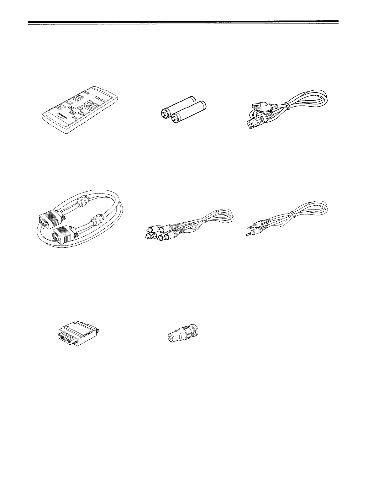
Accessories
The following accessories are included with this projector. Check for them; if any item is missing, please contact your
dealer.
Remote control unit (TNQE168)
Personal computer connection cable
[approx. 2 m (6.56 ft)]
(D-sub, 3-row 15 pin)
AAA/R03-size dry cell battery (x2)
(for checking operation)
AV connection cable
[approx. 1.5 m (4.92 ft)]
Power cord
[approx. 2.5 m (8.2 ft)]
Audio cable
[approx. 3 m (9.84 ft)]
(3.5 mm dia. stereo mini plug)
Conversion adapter for Mac
(for Macintosh)
BNC-RCA conversion plug
7

Controls and Features
Front Side /Top Surface / Right Side
Control panel
For details, refer to “Control Panel” (page 11).
Exhaust vents
Vents for cooling fans through which warm air comes out.
Do not block the exhaust vents, or heat builds up inside,
possibly causing a fire. Also, do not touch the vents, or this
could cause a low-temperature burn.
Carrying handle
Raise this handle when carrying the projector.
How to use the carrying handle
Carrying
When carrying the projector, do not shock it. Be careful to
keep its balance.
Do not carry it while the light source lamp is on or the cooling
fan is operating. This could cause personal injury.
handle
Adjustable foot (for adjusting upper/lower angles)
It is adjusted to be level when shipped from the factory.
Turning to extend the foot allows adjustment up to + 7°.
+7°
Extend Shorten
Built-in speaker (left)
Built-in speaker (right)
Lens
Projection lens, which is an electrically driven, approx. 1.5
x zoom lens. Before projection, remove the lens cap.
Lens cap
The cap has a string attached and the string is fixed to the
projector when shipped from the factory. It is recommended
that the cap be fitted on to prevent the lens becoming dirty
when the projector is not used.
Remote sensor
When operating with the remote control, aim it toward this
sensor. You can also operate the remote control by pointing
it to a screen and allowing the remote sensor to receive
the reflected light.
8
Controls and Features (cont.)
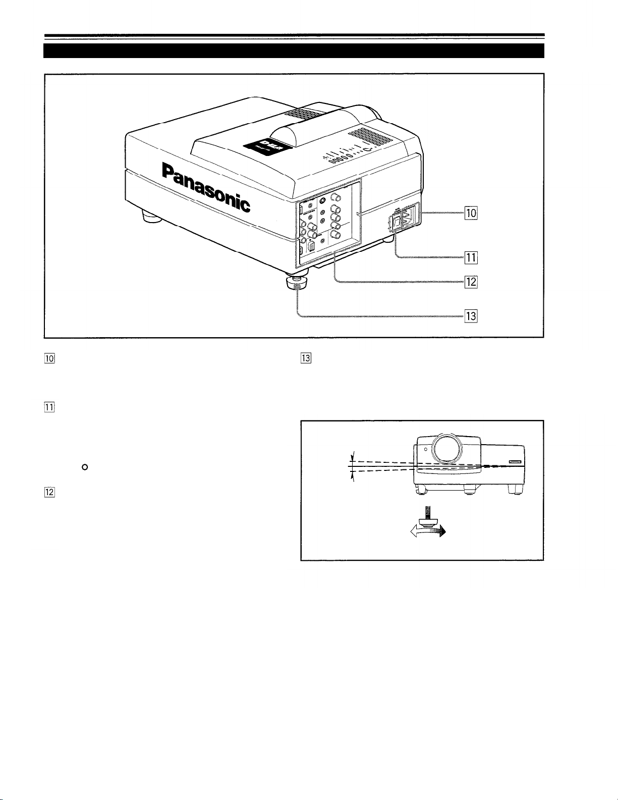
Left-hand side
AC IN (power input) terminal
This is the power input terminal where the supplied power
cord is connected. For details, refer to page 26.
MAIN POWER switch
This is the main power switch. When it is turned on, the
projector goes into stand-by state, and the STAND BY
indicator on the control panel comes on.
[ I ]
ON
OFF
: The main power turns on.
[ ]
: The main power turns off.
Connector panel
For details, refer to “Connector Panel” on page 13.
Adjustable foot (for horizontal angle adjustment)
It is set at the shortest position when shipped from the
factory Turn the foot to make the projector level. Adjustment
can be made in the range of + 1.5° and – 1.5° from the
horizontal position.
+1.5°
-1.5°
Extend Shorten
9
Controls and Features (cont.)
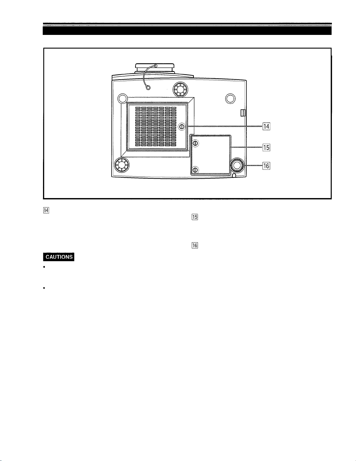
Bottom Surface
Air intake area (filter)
Air is taken in through this area to cool the light-source
lamp. If this area is blocked or if something that obstructs
taking in or exhausting air is placed around the projector,
heat may build up inside and could cause a fire. For details,
refer to “Precautions for Installation” on page 17.
Be careful as paper, cloth or soft cushion could be drawn in
if placed nearby Do not block the intake area, or heat may
build up and could cause a fire.
Clean the filter periodically. For details, refer to ‘Cleaning and
Replacing the Filter” on page 53.
Deposition of dirt on the filter works to reduce the cooling
effect, causing heat to build up inside, which could cause a
fire or malfunction.
Opening for replacing the light-source lamp
For replacing the light-source lamp, refer to “Replacing the
Light-Source Lamp” on page 50.
Fixing foot
10

Controls and Features (cont.)
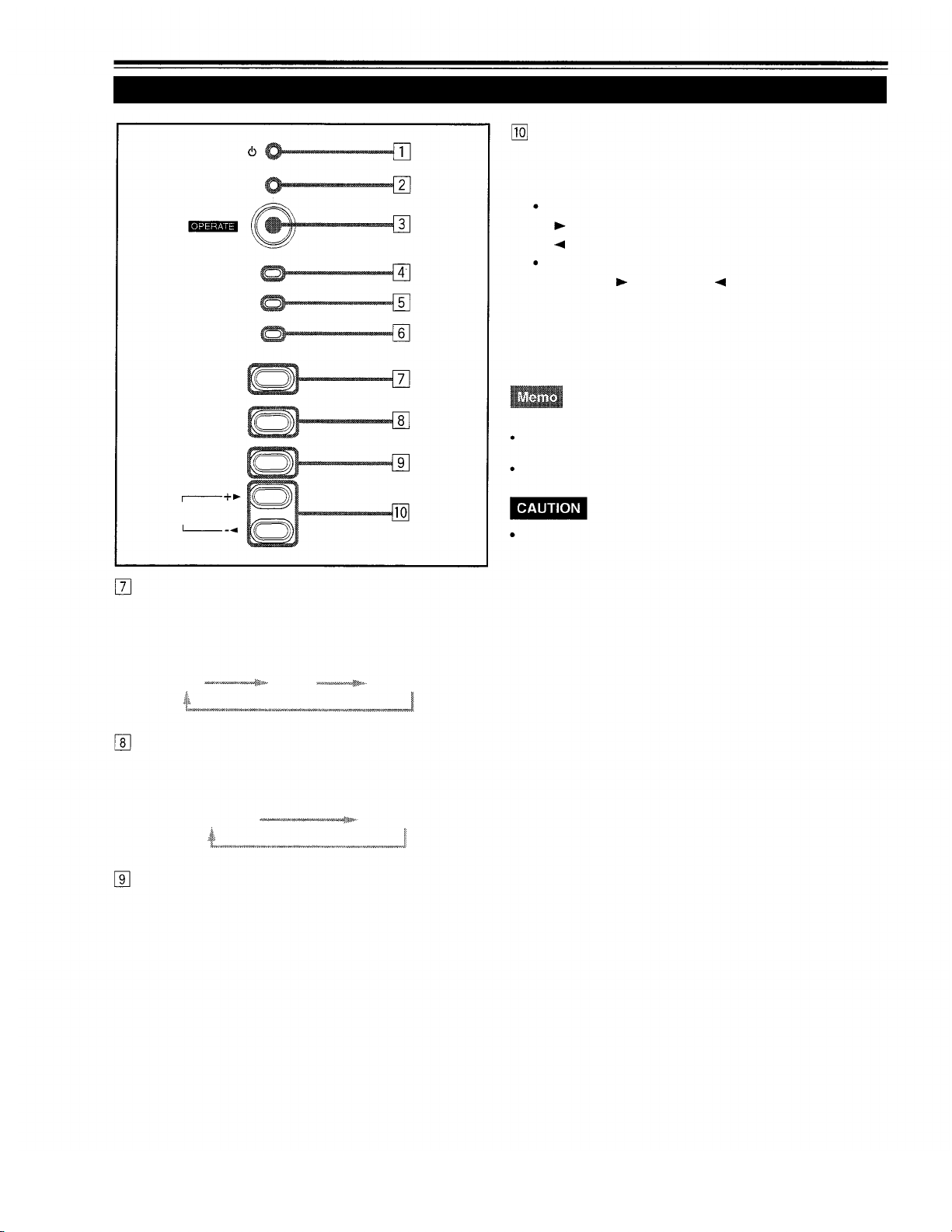
Control Panel
STAND BY
LAMP indicator
ON
Blinking
LAMP
TEMP
EMERGENCY
VIDEO
COMPUTER
SETTING
QUICK
ALIGN.
STAND BY Indicator
ON
Blinking
About the cool-down mode:
This projector has a function to cool down the heated lamp for a fixed
period of time after projection is finished. This feature is referred to as
the cool-down mode.
The purpose of the cool-down mode is to prevent inner parts
from being deformed or broken by heat from the heated lamp
as well as to prolong the life of the lamp. Do not turn off the
main power switch while in the cool-down mode. Also, do not
place the projector on its side or stand it upright; this may
block the exhaust vents.
:
When in stand-by mode.
:
When in cool-down mode.
TEMP indicator
ON : The temperature inside the projector is abnormally
While the TEMP indicator is on (during abnormal temperature), the
power is automatically cut off, and an emergency mode is shown
(with the EMERGENCY indicator blinking).
EMERGENCY indicator
Blinking
About the emergency mode:
The emergency mode is shown when the following anomalies have
occurred with the projector (the EMERGENCY indicator blinks). In
the emergency mode, projection is automatically interrupted and the
cooling fans operate for about 20 seconds.
When the air filter is displaced.
When the filter is clogged.
When the light-source lamp has suddenly gone off.
When the fans have stopped.
When the temperature inside has risen abnormally high.
When an emergency mode is shown:
After the cooling fans have stopped, turn off the main power
switch and unplug the power cord from the wall outlet.
Make sure the lamp-replacement cover and the air filter are
correctly installed. Then, plug in the power cord again and
operate the projector.
If it goes into an emergency mode again, after the cooling
fans have stopped, turn off the main power switch, unplug
the power cord, and call your dealer for repair.
: After the light-source lamp has been used for
more than approx. 900 hours.
:
Replace the lamp. Refer to “Replacing the LightSource Lamp” on page 50.
high.
: Something abnormal has occurred with the
projector.
OPERATE indicator
ON: When the projector is in operation (projecting)
OPERATE button
When the projector is in the stand-by mode, press this
button, and the main power switch is turned on, causing
the OPERATE indicator to light. Press it again, and the
projector goes into the cool-down mode, then stand-by
mode.
While in the cool-down mode:
If you press the OPERATE button, the projector is not tuned on.
11
Controls and Features (cont.)
Control Panel (Cont.)
STAND BY
LAMP
TEMP
EMERGENCY
VIDEO
QUICK ALIGN. button
While a menu screen is shown, use this button to adjust
the values for the item selected. When no menu is shown,
the quick alignment function works.
When a menu is shown
+
-
button:
button:
The value for the selected item increases.
The value for the selected item decreases.
When no menu is shown
Press the +
button and -
QUICK ALIGNMENT is displayed on the screen and the
quick alignment function works (TRACKING, PHASE, H.
POS. and V. POS. are automatically adjusted). When the
adjustment is finished, the display goes off automatically.
button at the same time:
COMPUTER
SETTING
QUICK
ALIGN.
VIDEO button
Use this button to select a device such as a video deck
connected to the AV IN terminal of the projector. Each time
you press the button, the device selected changes as
follows:
Y/C
VIDEO
Y,PB/B-Y,PR/R-Y
COMPUTER button
Use this button to select a device connected to the
COMPUTER -1 or -2 terminals. Each time you press the
button, the selection changes as follows:
COMPUTER 1
COMPUTER 2
The quick alignment function :
Works for computer input (COMPUTER- 1 and - 2 input terminals)
signals.
Does not work for video input (AV IN input terminal) signals.
Automatic adjustment with the quick alignment function
should be done on a bright still-picture screen. This function
may not work correctly on a dark screen or motion-picture
screen. If adjustment with this function is not satisfactory,
adjust TRACKING, PHASE, H. POS. and V. POS. manually
(see pages 33, 39 and 40).
SETTING button
Use this button to call up the setting menu. For details,
refer to “Making Basic Settings” on page 33.
12

Controls and Features (cont.)
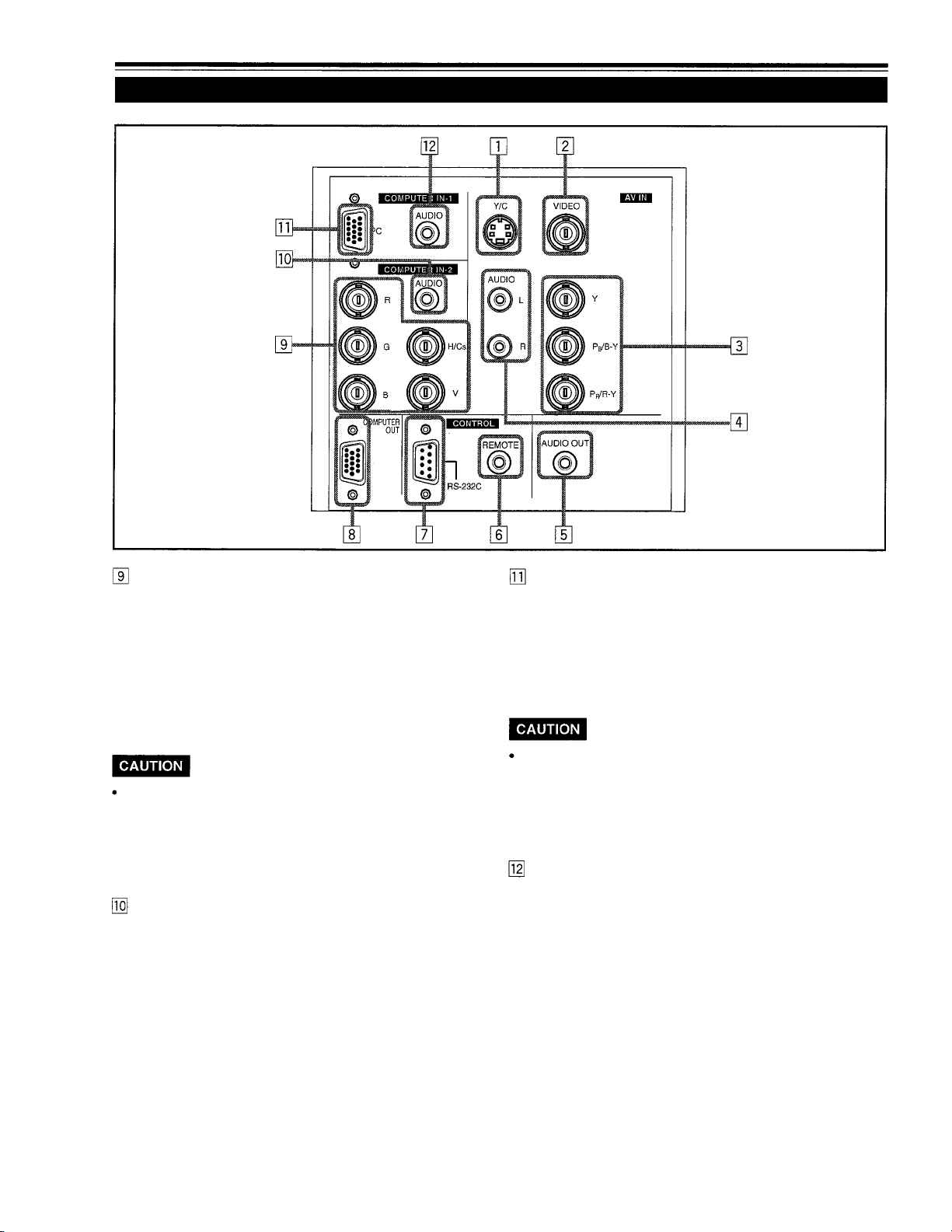
Connector Panel
Y/C (S video) input terminal (Mini DIN 4 pin)
Connect this terminal to the S video output terminal of a
video deck, etc.
VIDEO (composite video) input terminal (BNC)
Connect this terminal to the composite video output terminal
of a video deck, etc.
Y, PB/B-Y, PR/R-Y input terminals (BNC)
These are input terminals for component (Y, B-Y, R-Y)
signals and Hi-Vision base band (Y,
with component signal output terminals for NTSC or HiVision can be connected.
PB,
PR) signals. Devices
AUDIO L/R (Audio left/right) input terminals (pin jacks)
Of devices connected to the video input terminals, such
as a video deck, etc., the audio output terminals of the
device to de projected is connected to these terminals.
The input audio signal is reproduced by the speakers of
the projector. The signal is also output from the AUDIO
OUT terminal of the projector.
* When the input signal is stereo signal, connection should
be made to both L and R.
* Signals from a monaural device should be connected to
only L. That way, the projector’s speakers and the AUDIO
OUT terminal produce the same sound from both Land R.
AUDIO OUT (audio output) terminal (stereo mini jack)
Of input signals inputted to the projector, the audio signal
of the device being projected is output. Volume should be
adjusted using the VOL. (+/-) buttons on the remote control
or VOLUME on the setting menu. When a cable is
connected to this jack, no audio sound is produced from
the projector’s speakers.
REMOTE terminal (mini jack)
Connect an infrared remote control extension unit, etc. to
this jack.
* For details, consult your dealer.
RS-232C connector (D-sub 9 pin)
This is a RS-232C interface-specified connector. This
projector can be controlled by a computer connected
externally.
* For details, consult your dealer.
COMPUTER OUT (computer output) connector (D-sub
3-row 15 pin)
The computer input signal projected on the screen is output.
A display unit can be used by connecting it to this connector.
To select the proper audio input for video input:
The video input terminals (AV IN input terminals) can be switched
with the projector’s or remote control’s VIDEO button. However, since
this projector has only a single audio input terminal, reconnect audio
input in accordance with the AV device to be used.
13
Controls and Features (cont.)
Connector Panel (Cont.)
COMPUTER IN (computer input) -2 terminals (BNC)
These are input terminals for analog RGB signals, vertical
sync (V) signals, and horizontal sync (H) signals/composite
signals(Cs). Devices which have analog RGB signal output
terminals can be connected.
*Input of external sync signals is automatically
detected.
Detection of H/D signals or Cs signals causes automatic
switch to external sync. The priority order is H/D > Cs.
When computer-related signals are input, the uppermost
edge of the screen may appear bowing if the sync signal
input is composite sync (Cs) or G on sync signal. In that case,
use separate sync signals for vertical sync (V) and horizontal
sync (H).
AUDIO input terminal (stereo mini jack)
This is an audio input terminal for COMPUTER IN
(computer input) -2 terminal. Connect the audio output
signal of a device connected to COMPUTER IN (computer
input) -2 terminal.
* When input to COMPUTER -2 is selected, the audio signal
input is reproduced by the projector’s speakers. Also,
signals can be output from the AUDIO OUT (audio output)
terminal.
(However, if a cable is connected to AUDIO OUT (audio
output) terminal, audio sound does not come out from
the projector’s speakers.)
COMPUTER IN (computer input) -1 connector (D-sub
3- row 15 pin)
This is an input connector (PC) dedicated for computer
signals (RGB video signals and sync signals).
Connect the display output connector of the computer to
this connector. When a Macintosh computer is to be
connected, use the Conversion adapter for Mac supplied.
When computer-related signals are input, the uppermost
edge of the screen may appear bowing if the sync signal
input is composite sync (Cs) or G on sync signal. In that case,
use separate sync signals for vertical sync (V) and horizontal
sync (H).
AUDIO (audio) input terminal (stereo mini jack)
This is an audio input terminal for COMPUTER IN
(computer input) -1 terminal. Connect the audio output
signal of a device connected to COMPUTER IN (computer
input) -1 terminal.
* When input to COMPUTER -1 is selected, the audio signal
input is reproduced by the projector’s speakers. Also,
signals can be output from the AUDIO OUT (audio output)
terminal.
(However, if a cable is connected to AUDIO OUT (audio
output) terminal, audio sound does not come out from
the projector’s speakers.)
14

Controls and Features (Cont.)
Remote Control Unit
Remote control’s signal transmitter
COMPUTER button
Use this button to select the devices connected to the
projector’s COMPUTER IN (computer input) -1 and -2 input
connector/terminals. Each time you press the button, the
selection changes as follows:
COMPUTER 1
VIDEO button
Use this button to select the devices such as a video
connected to the projector’s AV IN (AV input) terminals. Each
time you press the button, the selection changes as follows:
Y/C
VIDEO
COMPUTER 2
Y,PB/B-Y,PR/R-Y
Quick alignment function:
Works only for computer-related (COMPUTER-1 and-2 input
connector/terminals) signals.
ZOOM (T/W) button
Use these buttons to increase or decrease the screen size.
(The projector’s projection lens is an electrically driven
zoom lens of about 1.5 x.)
T
: The screen size decreases.
W:
The screen size increases.
FOCUS (+/-) button
Use these buttons to adjust the focus of the projected video.
+: The focus point becomes more distant.
-: The focus point becomes nearer.
MENU/ENTER button
Use this button to display the main menu. While the main
menu is displayed, pressing this button displays a details
setting (submenu) for items with details settings.
Cursor
While the main menu is displayed, use these buttons to
select an item to adjust or make adjustment.
button
AV MUTING (On/Off) button
Use this button to turn off the video image and audio sound
temporarily. Pressing it again makes the video image and
audio sound to resume.
QUICK ALIGN. (Quick Alignment) button
Use this button to automatically adjust TRACKING, PHASE,
H. POS. and V. POS. of the projected video. During the
automatic adjustment, QUICK ALIGNMENT appears on
the screen, and disappears after it is finished.
Does not work for video input (AV IN terminals) signals.
Automatic adjustment with the quick alignment function should be
done on a bright still-picture screen. This function may not work
correctly on a dark screen or motion-picture screen. If adjustment
with this function is not satisfactory, adjust TRACKING, PHASE, H.
POS. and V. POS. manually (see pages 33, 39 and 40).
PRESET button
While making adjustment on the main or setting menu,
use this button to reset the setting of the selected item to
the factory-set value. This button works only for numerical
settings and does not work for switching ON to OFF.
PAGE BACK button
While a details setting is displayed, use this button to go
back to the previous page.
VOL. (Volume) (+/-) button
Use these buttons to adjust the sound volume:
+: Increases the volume level.
-: Decreases the volume level.
OPERATE button
To turn on the power, press this button for one second or
more.
* About 30 seconds after the power has been turned on, a
video image will appear on the screen.
15
Controls and Features (cont.)
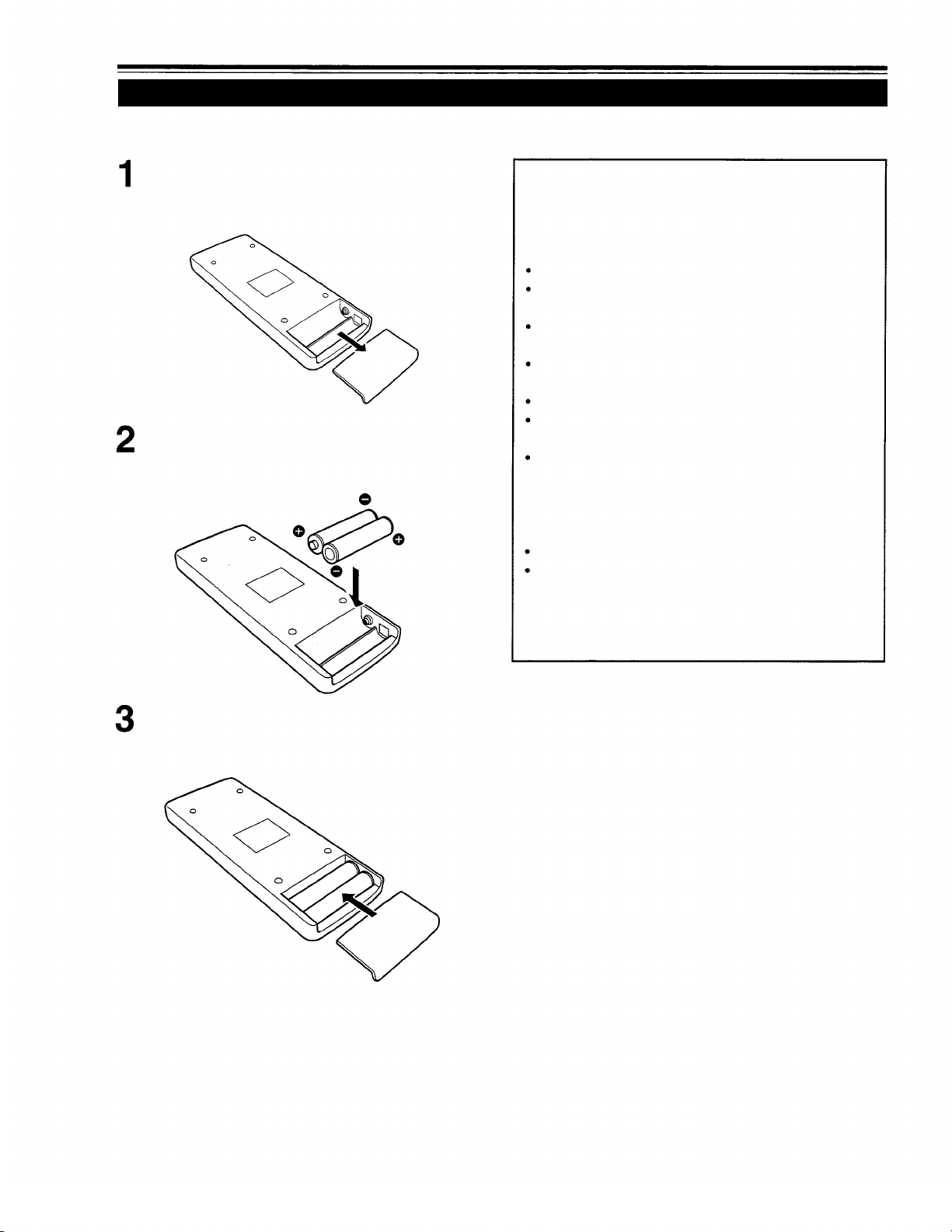
Installing Batteries
Install batteries in the remote control. If the remote control has started to work erratically, replace the batteries.
Open the back cover.
While pushing on the back cover, slide it in the direction
of the arrow.
Install the batteries.
Place the two batteries (AAA/R03-size) supplied in the
remote control as illustrated below.
Precautions for using batteries
If batteries are used incorrectly, they may crack or
leak liquid. This could cause a fire, burn, malfunction,
or staining or damaging the surrounding.
Beware of the following:
Do not mix new and old batteries.
Do not mix different types of batteries as they differ in
characteristics.
Place batteries so they match the polarities indicated:
(+) to (+) and (-) to (-).
Be sure to put the minus (-) end in first to avoid shortcircuiting.
Use only designated batteries.
Remove the batteries if not used for a prolonged period
of time.
When the batteries are exhausted, replace them
immediately. Otherwise, liquid could leak, or malfunction
could occur due to leaked liquids. If the leaked liquid
contacts the skin, wipe it off with a cloth, otherwise the
skin could become irritated.
Do not put batteries into fire or try to recharge them.
Batteries run for six months to one year in normal use.
But the batteries supplied are for confirming operation
and may not run that long. When the remote control starts
failing to work properly, replace the batteries with new
ones.
Close the back cover.
Slide the back cover in the direction of the arrow until a
click is heard.
16

Installing the Projector
Precautions for Installation
Do not install the projector in places where :
There is much water, humidity or dust.
The projector may be subjected to oil smoke or cigarette smoke.
The surface is soft, such as a carpet or cushion.
The projector may be subjected to direct sunlight.
Temperature is high or humidity is low.
Allowable operation temperature range: + 5°C to + 35°C (41°F to 95°F)
Allowable relative humidity range:
Allowable storage temperature range:
When installing the projector, observe the followings:
Do not use the projector placed on its side.
Avoid using the projector placed on its side. This could cause a malfunction.
Use the projector within the installed angle.
Avoid using the projector inclined ±30° or more right-to-left or left-to-right. This could cause color variation or harm the lamp
life.
Do not block the exhaust vents.
Do not use a cover which encloses the projector air-tight or blocks the exhaust vents. Allow sufficient space around the
projector. When the projector is enclosed in a space of the following dimensions, use an air conditioner so the temperature
inside becomes equal to the outside temperature.
20% to 80% (no condensation)
-10°C to +60°C (14°F to 140°F)
Allowable minimum space required
20cm (7 - 7/8”)
20cm (7 - 7/8”)
50cm (19 - 3/4”)
20cm (7 - 7/8”)
20cm (7 - 7/8”)
17
Installing the Projector (Cont.)
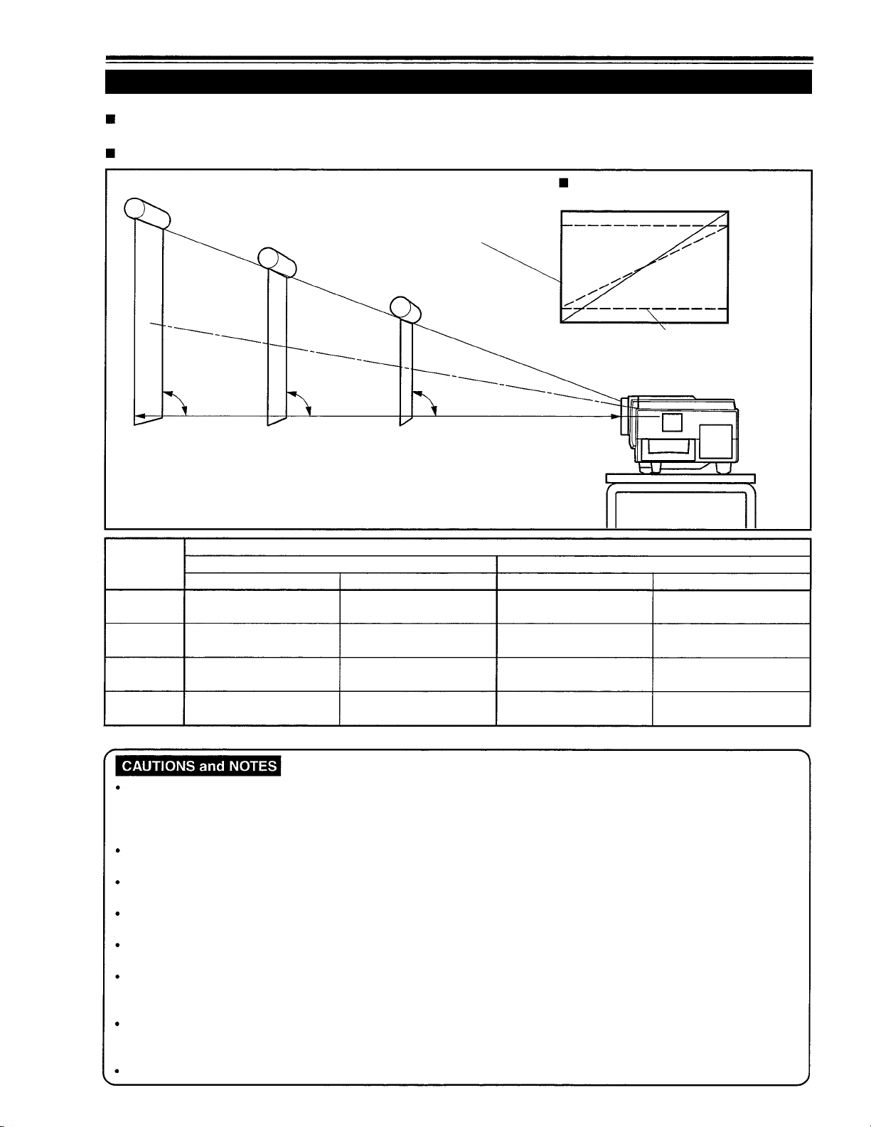
Projection Distance and Screen Size
The projector’s projection lens is a zoom lens of about 1.5 x. The screen size at the maximum enlargement is 1.5
times that of the minimum size.
The projection distance that can be focused is 2.5 to 20 m. Install the projector within this range.
Screen
Change of projection screen
according to aspect ratio
Screen with 4 : 3 aspect ratio
Screen with 16 : 9 aspect ratio
90°
Install the projector so the lower
edge of the projection screen is
at the same height as the lens’
center line.
Projection
distance
8.2 ft
(2.5 m) (approx. 107 cm) (approx. 160 cm)
16.4 ft
(5 m)
32.8 ft
(10 m)
65.6 ft
(20
m)
Minimum projection screen
When screen aspect ratio is 4 : 3 When screen aspect ratio is 16 : 9
42” 63”
86”
(approx. 219 cm)
172”
(approx. 437 cm)
345” 521”
(approx. 877 cm) (approx. 1,323 cm)
90°
Projection screen size (diagonal length)
Maximum projection screen
(approx. 325 cm)
(approx. 657 cm)
*Also, refer to the table of “Relationship Between Projection Distances and Projection Screen Sizes” on page 19 as a reference.
90°
Center line of the lens
128”
259”
Minimum projection screen Maximum projection screen
39” 57”
(approx. 100 cm)
79”
(approx. 201 cm)
158”
(approx. 402 cm)
317”
(approx. 806 cm)
(approx. 144 cm)
117”
(approx. 297 cm)
237”
(approx. 601 cm)
478”
(approx. 1,214 cm)
Install the screen so the lower edge of the projected picture aligns with the extended center line of the projector’s lens.
That way, the lower edge of the picture projected on a 4 : 3 aspect ratio screen aligns with the extended center line of the
lens. Also, the screen must be at right angles with the extended center line of the lens (so that projection occurs at right
angles with the screen).
When installing the screen, use a 4 : 3 aspect ratio picture.
(A 16 : 9 aspect ratio picture is projected based on the width of the range in which a 4 : 3 aspect ratio picture is projected.)
The diagonal length of a 16 : 9 aspect ratio picture is about 91.8% that of a 4 : 3 aspect ratio picture. This value is a guide
and should be used as a reference.
When projecting at the maximum projection distance (20 m/65.6 ft), we recommend that the projector be used with the
zoom on the Tele (T).
If sunlight or lamp light strikes the projection screen directly, the picture becomes whitish and dim. Be sure to use a
curtain, etc. to shield the light.
Trapezoidal distortion may not be corrected.
Adjust the projector within the range of angle adjustment (up/down adjustment angle: +7°; horizontal adjustment angle:
±1.5°) so that it is set up level.
The numeric values listed in the table of Relationship between Projection Distances and Screen Sizes on page 19 are
provided only as a guide or reference. The projection sizes may vary within manufacturing tolerances of the projection
lens.
When hanging the projector from the ceiling, use a dedicated hanging fixture.
18
 Loading...