

Page 1
KLC/KLCUL
Warnings and Cautions
!
!
!
!
Phone: 800.894.0412 - Fax: 888.723.4773 - Web: www.clrwtr.com - Email: info@clrwtr.com
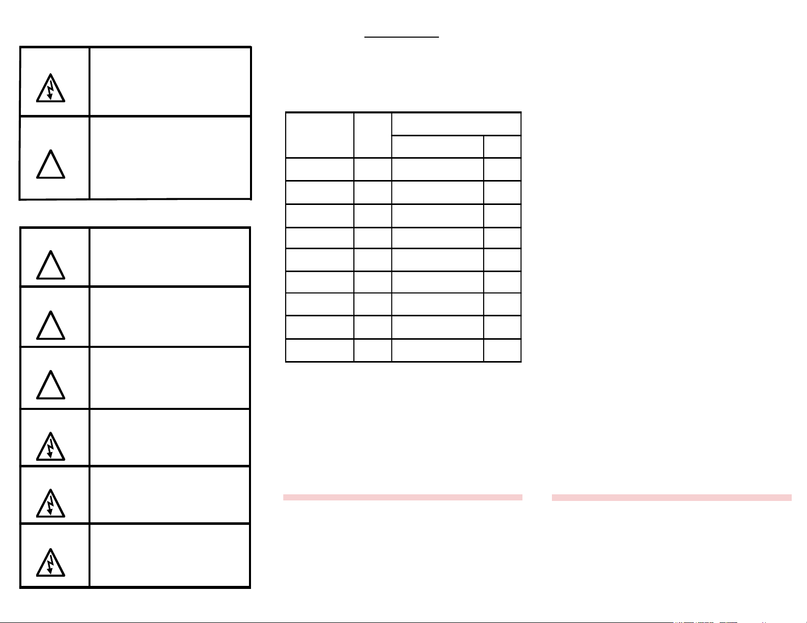
Warning
Warning
Dangerous Voltage Warning: warns of
situations in which a high voltage can
cause physical injury and/or equipment
damage. The text next to this symbol
describes ways to avoid the danger.
General Warning:warns of situations
that can cause physical injury and/or
equipment damage by means other
than electrical. The text next to this
symbol describes ways to avoid the
danger.
General Safety Instructions
Warning
Warning
Warning
Be sure to read, understand, and
follow all safety instructions.
Only qualified electricians should
carry out all electrical installation and
maintenance work on the output filter.
All wiring must be in accordance with
the National Electrical Code (NEC)
and/or any other codes that apply to
the installation site.
Field Wiring
KLCUL Field Wiring Connection Terminals
Compression type terminals are provided for all field
wiring connections. The wire size capacity ranges
and tightening torque for the grounding and power
terminals are listed in the table.
KLCUL
Model
Numbers
KLCUL2A to
KLCUL12A
KLCUL16A to
KLCUL80A
KLCUL110A to
KLCUL130A
KLCUL160A 3/8" 6 AWG - 250 MCM 275
KLCUL200A to
KLCUL250A
KLCUL305A 1/2" 4 AWG - 600 MCM or
KLCUL362A 1/2" (2) 4 AWG - 350 MCM 275
KLCUL420A to
KLCUL600A
KLCUL750A 1/2" 6 AWG - (3) 300 MCM 275
See Trans-Coil website or brochure for
dimensions tables.
Ground
Stud
Size
1/4" 18 - 12 AWG 10
1/4" 18 - 4 AWG 20
3/8" 6 - 2/0 AWG 120
3/8" (2) 14 - 2/0 AWG 120
1/2" (2) 2 AWG - 600 MCM 500
Input and Output
Motor Power
Wire Size
(2) 1/0 AWG - 250 MCM
Torque
(in. - lb.)
500
Performance and Protection for Drives
Installation
Guide
Warning
Warning
Warning
Disconnect all power before working
on the equipment. Do not attempt any
work on a powered output filter.
The KLC, VFD, motor, and other
connected equipment must be
properly grounded.
The VFD terminals and connected
cables are at a dangerously high
voltage when power is applied to the
VFD, regardless of motor operation.
Please contact TCI Technical Support or
your TCI distributor for application
information regarding the use of KLC
output filters on the output side of the
VFD.
Page 2
KLC/KLCUL
Phone: 800.894.0412 - Fax: 888.723.4773 - Web: www.clrwtr.com - Email: info@clrwtr.com
Output Filter
Installation Instructions
Installation Checklist
• Make sure that the installation location will not be
exposed to direct sunlight, rain or dripping liquids,
corrosive liquids or gases, explosive or combustible
gases or dust, excessive airborne dirt and dust, or
excessive vibration.
• Select a mounting area that will allow adequate
cooling air and maintenance access.
• Make sure that all wiring conforms to the
requirements of the National Electric Code (NEC)
and/or other applicable electrical codes.
• Connect the KLC Output Filter grounding lug to a
dedicated system ground to ensure safety and filter
performance. Use a properly sized grounding
conductor.
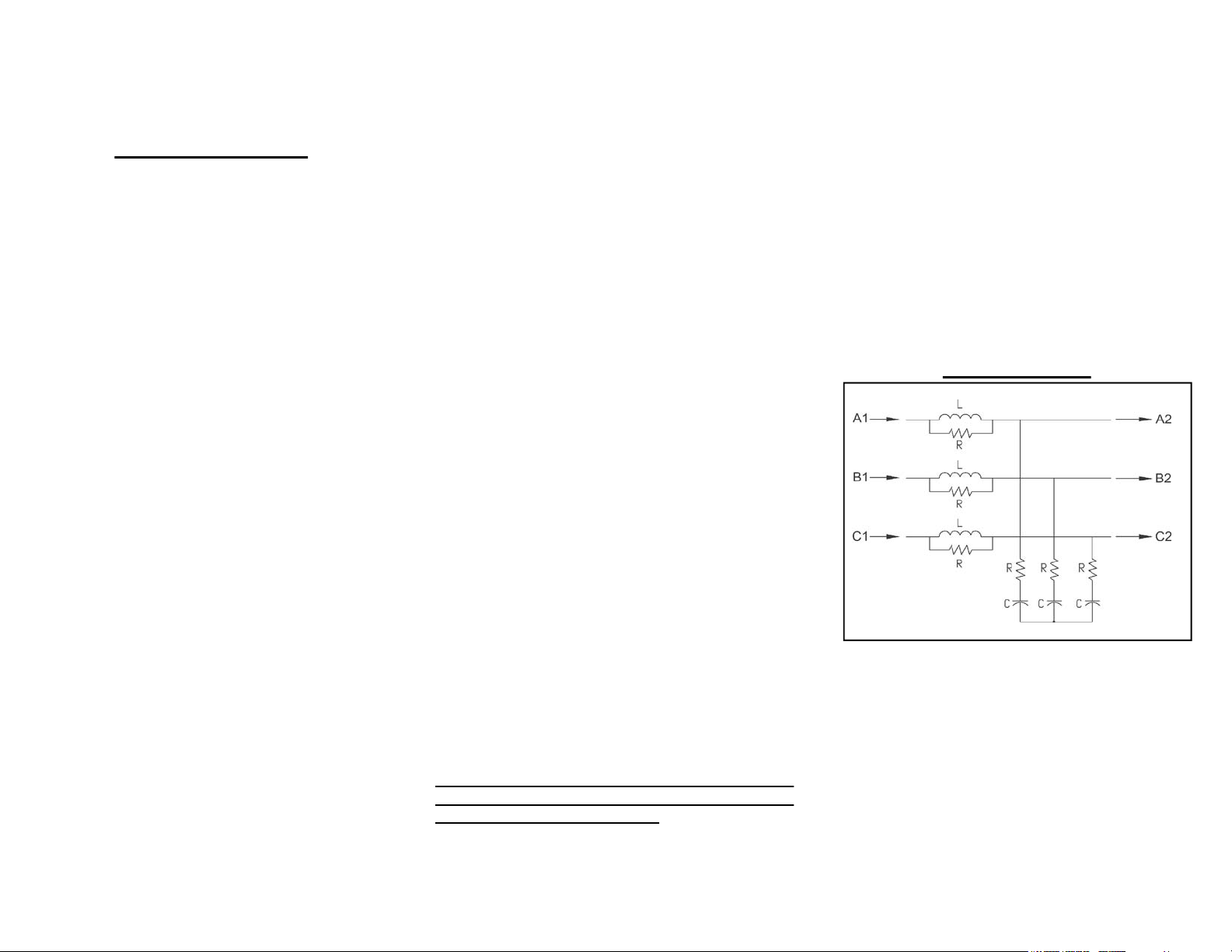
• Wire the output power terminals of the VFD, T1(U),
T2(V), & T3(W) to the input terminals of the KLC
filters L1, L2, and L3.
• Wire the output power terminals, of the KLC, T1, T2,
& T3 to the motor power connections.
• Make sure the VFD is set for operating modes and
ranges that are compatible with the KLC Output
Filter.
• Check the entire system thoroughly before
energizing and operating any equipment.
When you receive the unit, you should immediately
inspect the shipping container and report any
damage to the shipping carrier who delivered the
unit.
Verify the Application
Make sure the KLC output filter is correct for the
application. The current ratings of the KLC should be
sized to handle the FLA rating of the motor but not to
exceed 110% of the drive output current rating. This
output filter is best applied matched closely to the
load. The KLC output filter is not selected by the drive
input current rating.
Variable Frequency Drive Settings
Make sure that the variable frequency drive will be
set for operation modes and ranges that are
compatible with the KLC output filter:
• Maximum output frequency: 60 Hz
• Set the drive carrier frequency to 8 kHz or below.
• Mode of operation: Do not use with DC braking
unless the drive application has been confirmed by
TCI Technical Support.
• Do not use on overhauling loads without bus voltage
control
Mounting an open panel unit
If you are mounting an open panel unit in your own
enclosure, you must provide an enclosure that is
adequately sized and ventilated sufficiently to prevent
overheating. The filter is designed with a maximum
ambient temperature of 40°C (104°F). If the ambient
temperature exceeds this value it is the responsibility
of the customer to provide auxiliary cooling to reduce
the ambient operating temperature around the KLC
filter. TCI strongly recommends using auxiliary
cooling devices such as cooling fans, heat
exchangers, or possibly air conditioning units when
required to maintain the proper operating
temperature.
Position the KLC filter to be within 10 (wire) feet from
the drive output termincals. The KLC must be
mounted so that the inherent line reactor is positioned
vertically. Mounting it vertically is important for
natural convection cooling.
Power Wiring
The conduit and wiring from the output of the variable
frequency drive to the motor must be routed to the
KLC and then to the motor. TCI recommends a
separate dedicated conduit run for each
drive/filter/motor run unless properly shielded and
segregated wiring procedures are practiced. Parasitic
and induced capacitance can greatly reduce the
effectiveness of the filter performance. Under no
circumstances should you wire both control and
power wire in the same conduit unless the wire way is
specifically designed for this practice. The unit
temperature is sensitive to lead wire oversizing.
Avoid lead wires more than five times oversized by
copper cross sectional area and operating current,
regardless of the material used. Use 75°C copper
conductors only or the equivalent, unless the wire
connector is marked for Al/Cu, then the use of
aluminum wire is permitted. Use copper conductor
only on units rated above 80 amps.
WiringCable Entry Locations
TCI has not provided knock-outs due to the wide
variety of application requirements. TCI allows
installing electricians the option of locating the cable
openings at a point of their choosing.
Grounding
The KLC panel equipment grounding lug must be
connected to the ground of the premises wiring
system. This can be conducted by identifying a
known premises ground near by the filter or running
a special ground dedicated for this application. The
ground connection must be made using a wire
conductor. Metallic conduit is not a suitable
grounding conductor. The integrity of all ground
connections should be periodically checked.
Wiring Diagram
Product Specifications
u Current Rating: 2 - 750 Amps
u UL and CUL Listed
u Open and ULType 1 Enclosures
u Efficiency > 98%
u Insulation Rating: 600V Class
u Insulation Class:Class H (180°C or Better)
u Altitude (Maximum): 1000 m
u Lead Length: 3000 ft (Specific Applications,
consult TCITech Support over 1000 ft)
u Operating Temp: 40°C Ambient
 Loading...