

Page 1
DLPTMBased Projector Commercial Use
Operating Instructions
Read these instructions completely before operating this unit.
TQBJ 0146-1
POWER
ON OFF
RGB1RGB
2
AUX
MENU
STD
LENS
OSD
1
4
7
2
5
8
3
6
9
0
NEXT
USER
LIGHT
ID ALL
ASPECT
ID SET
Projector
Computer
Numetric
BRIGHT
CONTRAST
ON SCREEN
SYSTEM
SEL
FUNC
1
D.ZOOM
ENTER
PAGE UP
PAGE DOWN
VIDEO
SHUT
S-
VIDEO
FREEZE
SHUTTER
AUTO
SETUP
LASER ON/OFF
Model No.
PT-D7700U
PT-DW7000U
Page 2
2
Dear Panasonic Customer:
This instruction booklet provides all the necessary operating information that you might require. We hope it will help
you to get the most performance out of your new product, and that you will be pleased with your Panasonic DLP
TM
based projector.
The serial number of your product may be found on its back. You should note it in the space provided below and
retain this booklet in case service is required.
Model number: PT-D7700U / PT-DW7000U
Serial number:
IMPORTANT SAFETY NOTICE
WARNING: TO REDUCE THE RISK OF FIRE OR ELECTRIC SHOCK, DO NOT EXPOSE
THIS PRODUCT TO RAIN OR MOISTURE.
The lightning flash with arrowhead symbol, within an equilateral triangle, is intended to alert
the user to the presence of uninsulated “dangerous voltage” within the Product's enclosure
that may be of sufficient magnitude to constitute a risk of electric shock to persons.
The exclamation point within an equilateral triangle is intended to alert the
user to the presence of important operating and maintenance (servicing)
instructions in the literature accompanying the product.
CAUTION: This equipment is equipped with a three-pin
grounding-type power plug. Do not remove the
grounding pin on the power plug. This plug will
only fit a grounding-type power outlet. This is a
safety feature. If you are unable to insert the plug
into the outlet, contact an electrician. Do not
defeat the purpose of the grounding plug.
WARNING
RISK OF ELECTRIC
SHOCK. DO NOT OPEN
MISE EN GARDE-
RISQUE DE CHOC ÉLECTRIQUE.
NE PAS OUVRIR.
WARNUNG-
ZUR VERMEIDUNG EINES ELEKTRISCHEN
SCHLAGES GERÄT NICHT ÖFFNEN.
Do not remove
Page 3

3
WARNING:
This equipment has been tested and found to comply with the limits for a Class B digital
device, pursuant to part 15 of the FCC Rules. These limits are designed to provide
reasonable protection against harmful interference in a residential installation. This
equipment generates, uses and can radiate radio frequency energy and, if not installed and
used in accordance with the instructions, may cause harmful interference to radio
communications. However, there is no guarantee that interference will not occur in a
particular installation. If this equipment does cause harmful interference to radio or television
reception, which can be determined by turning the equipment off and on, the user is
encouraged to try to correct the interference by one or more of the following measures:
– Reorient or relocate the receiving antenna.
– Increase the separation between the equipment and receiver.
– Connect the equipment into an outlet on a circuit different from that to which the receiver
is connected.
–
Consult the dealer or an experienced radio/TV technician for help.
FCC CAUTION: To assure continued compliance, use only shielded interface cables when
connecting to computer or peripheral devices. Any unauthorized changes or
modifications to this equipment could void the user’s authority to operate.
WARNING:
Not for use in a computer room as defined in the Standard for the Protection of Electronic Computer/Data
Processing Equipment, ANSI/NFPA 75.
NOTICE: This product has a High Intensity Discharge (HID) lamp that contains a small amount
of mercury. It also contains lead in some components. Disposal of these materials
may be regulated in your community due to environmental considerations. For
disposal or recycling information please contact your local authorities, or the
Electronics Industries Alliance: <http://www.eiae.org.>
Declaration of Conformity
Model Number: PT-D7700U / PT-DW7000U
Trade Name: Panasonic
Responsible Party: Matsushita Electric Corporation of America
One Panasonic Way, Secaucus, NJ 07094
Telephone Number: 1-800-524-1448 or 1-800-526-6610
Email: pbtsservice@panasonic.com
This device complies with Part 15 of the FCC Rules. Operation is subject to the
following two conditions: (1) This device may not cause harmful interference, and (2)
this device must accept any interference receiver, including interference that may
cause undesired operation.
Page 4

4
IMPORTANT SAFETY NOTICE ..................................2
Precautions with regard to safety ............................5
Accessories ................................................................7
Precautions on handling ...........................................8
Examples of system expansion................................9
Name and function of parts.....................................10
Remote control ................................................................10
Front and side of the projector ........................................12
Rear view of the main unit...............................................13
Controls on rear panel.....................................................13
Side-mounted connection terminals ................................14
Using the remote control unit .................................15
Loading dry cells .............................................................15
Effective range of remote control operation ....................15
Setting projector ID number to remote control ................16
Using the remote control as a PC mouse........................17
Using a wired remote control...........................................17
Installation ................................................................18
Adjusting the leveling feet ...............................................18
Projection scheme...........................................................18
Installation geometry .......................................................18
Projection distances by the type of projection lenses (optional)
..19
Connection ...............................................................24
Before starting connection...............................................24
Example of connecting with VIDEO devices ...................25
Example of connecting with personal computers ............26
Example of connecting with the signal selector...............27
Installation of input module (optional)...................28
Installing the input module...............................................28
Connecting signals to the input module ..........................30
Connecting the signal to the analog RGB signal input module
..31
Connecting the signal to the video signal input module ..32
Connecting the signal to the serial digital signal input module
..34
Connecting signals to the DVI signal input module .........37
How to install and remove the projection lens (optional)
..........38
How to install the projection lens.....................................38
How to remove the projection lens ..................................38
Projection..................................................................39
Powering up the projector ...............................................39
Making adjustment and selection ....................................39
Powering off the projector ...............................................40
How to adjust the lens .............................................41
How to adjust the lens focus, lens zoom and lens shift (optical shift)
..41
Adjustment range after lens position (optical shift)..........41
How to adjust the lens for addressing unevenness of focusing
..42
Automatic adjustment (AUTO SETUP)...................43
Registration of input signal data ............................44
Registration of new data..................................................44
Renaming the registered signals.....................................44
Clearing the data of registered signals
...............................
45
Sub memory ....................................................................46
Using the FREEZE function ....................................48
Using the SHUTTER function..................................48
Using the digital zoom (– D.ZOOM +) function ...............
48
On-screen menus.....................................................49
Structure of menu screens ..............................................49
Basic operations on menu screen ...................................50
Returning to the previous screen ....................................50
Menu items shown in gray characters.............................50
Menu items setting ..........................................................50
Resetting to the factory default........................................50
Adjusting the picture ...............................................51
Switching the picture mode .............................................51
Adjusting Contrast / Bright / Color / Tint ..........................52
Registering the picture mode settings as presettings......53
DYNAMIC IRIS setting ....................................................54
Adjusting the color temperature ......................................55
Sharpness / Gamma / Noise reduction ...........................56
To display pictures complying with the sRGB standard ..56
Adjusting the position .............................................57
Shift adjustment...............................................................57
Size adjustment...............................................................58
Clock phase adjustment ..................................................59
Keystone distortion correction .........................................60
How to use ADVANCED MENU ...............................61
DIGITAL CINEMA REALITY ...........................................61
FORMAT (To input BETACAM with YCbCr 480i) ...........61
Blanking adjustment ........................................................62
Adjusting the input resolution ..........................................63
Adjusting the clamp position............................................64
Edge blending adjustment...............................................65
How to switch the input impedance (signal level)
of the synchronization signal ...........................................66
Raster position ................................................................67
Changing the display language ..............................68
How to change the system format..........................69
How to use RGB REALITY mode ............................70
Option settings.........................................................71
ID number setting ............................................................71
Installation Setting ...........................................................72
Lamp select .....................................................................73
Lamp power.....................................................................73
RS232C SETTING (Procedure of setting communication conditions)
..74
Position of on-screen indications.....................................74
System information..........................................................74
Adjusting color matching .................................................75
Adjusting the color matching using a colorimeter............76
Video setting....................................................................77
Automatic adjustment......................................................77
Output resolution (D7700U only).....................................78
Auto signal.......................................................................78
Fan control ......................................................................78
P IN P ..............................................................................79
Setting FUNC1 ................................................................80
Password.........................................................................80
How to change the signal for the
ET-MD95VM2 (optional) ...........................................81
Using the serial terminals .......................................82
Examples of connection .................................................82
Pin assignments and signal names.................................82
Communication conditions (Factory setting) ...................82
Basic format ....................................................................82
Control commands ..........................................................83
Cable specifications ........................................................83
Using the REMOTE 2 terminal ................................84
Displaying the internal test pattern ........................85
Cycle of displayed internal test patterns..........................85
RS-422 control functions.........................................85
Setting the security..................................................86
Setting the password.......................................................86
Changing the password...................................................87
Setting the text ................................................................87
Changing the text ............................................................87
How to use CP OPTION ...........................................88
Setting the on-screen indication function ........................88
Setting the system format................................................89
How to use network module (optional) ..................90
Initial setting of network module ......................................91
Accessing from the Web browser....................................92
Returning the network module setting back to the factory setting
..97
Indication of monitor lamp ......................................98
Cleaning and replacement of air filter....................99
Procedure of cleaning .....................................................99
Replacement of lamp unit .....................................100
Timing of lamp unit replacement ...................................100
Procedure of lamp unit replacement .............................101
Before asking for service ......................................103
Specifications.........................................................104
Appendix.................................................................106
Outside dimensions...............................................107
Français Information..............................................108
Contents
Page 5

5
Precautions with regard to safety
WARNING
If a problem occurs (such as no image) or if you notice smoke or a strange smell coming
from the projector, turn off the power and disconnect the power cord from the wall outlet.
• Do not continue to use the projector in such cases, otherwise fire or electric shocks could result.
• Check that no more smoke is coming out, and then contact an Authorized Service Center for repairs.
• Do not attempt to repair the projector yourself, as this can be dangerous.
Do not install this projector in a place which is not strong enough to take the full weight
of the projector.
• If the installation location is not strong enough, it may fall down or tip over, and severe injury or damage could
result.
• Installation work (such as ceiling suspension) should only be carried out by a qualified technician.
• If installation is not carried out correctly, there is the danger that injury or electric shocks may occur.
If foreign objects or water get inside the projector, or if the projector is dropped or the
cabinet is broken, turn off the power and disconnect the power cord from the wall outlet.
• Continued use of the projector in this condition may result in fire or electric shocks.
• Contact an Authorized Service Center for repairs.
Do not cover the air filter, the air inlet and exhaust vents.
• Doing so may cause the projector to overheat, which can cause fire or damage to the projector.
Do not overload the wall outlet.
• If the power supply is overloaded (for example, by using too many adapters), overheating may occur and fire
may result.
Do not remove the cover or modify it in any way.
• High voltages which can cause fire or electric shocks are present inside the projector.
• For any inspection, adjustment and repair work, please contact an Authorized Service Center.
Clean the power cord plug regularly to prevent it from becoming covered in dust.
• If dust builds up on the power cord plug, the resulting humidity can damage the insulation, which could result in
fire. Pull the power cord out from the wall outlet and wipe it with a dry cloth.
• If not using the projector for an extended period of time, pull the power cord plug out from the wall outlet.
Do not do anything that might damage the power cord or the power cord plug.
• Do not damage the power cord, make any modifications to it, place it near any hot objects, bend it excessively,
twist it, pull it, place heavy objects on top of it or wrap it into a bundle.
• If the power cord is used while damaged, electric Shocks, short-circuits or fire may result.
• Ask an Authorized Service Center to carry out any repairs to the power cord that might be necessary.
Do not handle the power cord plug with wet hands.
• Failure to observe this may result in electric shocks.
Insert the power cord plug securely into the wall outlet.
• If the plug is not inserted correctly, electric shocks or overheating could result.
• Do not use plugs which are damaged or wall outlets which are coming loose from the wall.
Do not place the projector on top of surfaces which are unstable.
• If the projector is placed on top of a surface which is sloped or unstable, it may fall down or tip over, and injury or
damage could result.
Do not place the projector into water or let it become wet.
• Failure to observe this may result in fire or electric shocks.
Do not disassemble the lamp unit.
• If the lamp section breaks, it may cause injury.
Page 6

6
Precautions with regard to safety
Do not place liquid containers on top of the projector.
• If water spills onto the projector or gets inside it, fire or electric shocks could result.
• If any water gets inside the projector, contact an Authorized Service Center.
Do not insert any foreign objects into the projector.
• Do not insert any metal objects or flammable objects into the projector or drop them onto the projector, as doing
so can result in fire or electric shocks.
After removing the battery from remote control unit, keep it away from the reach of children.
• The battery can cause death by suffocation if swallowed.
• If the battery is swallowed, seek medical advice immediately.
Do not allow the + and - terminals of the battery to come into contact with metallic
objects such as necklaces or hairpins.
• Failure to observe this may cause the battery to leak, overheat, explode or catch fire.
• Store the battery in a plastic bag and keep it away from metallic objects.
Insulate the battery using tape or similar before disposal.
• If the battery comes into contact with metallic objects or other batteries, it may catch fire or explode.
Replacement of the lamp unit should only be carried out by a qualified technician.
• The lamp unit has high internal pressure. If improperly handled, explosion might result.
• The lamp unit can easily become damaged if struck against hard objects or dropped, and injury or malfunctions
may result.
Do not set up the projector in humid or dusty places or in places where the projector may
come into contact with smoke or steam.
• Using the projector under such conditions may result in fire or electric shocks.
When disconnecting the power cord, hold the plug, not the cord.
• If the power cord itself is pulled, the cord will become damaged, and fire, short-circuits or serious electric shocks
may result.
Always disconnect all cables before moving the projector.
• Moving the projector with cables still attached can damage the cables, which could cause fire or electric shocks
to occur.
Do not place any heavy objects on top of the projector.
•
Failure to observe this may cause the projector to become unbalanced and fall, which could result in damage or injury.
Do not short-circuit, heat or disassemble the battery or place it into water or fire.
• Failure to observe this may cause the battery to overheat, leak, explode or catch fire, and burns or other injury
may result.
When inserting the battery, make sure the polarities (+ and -) are correct.
• If the battery is inserted incorrectly, it may explode or leak, and fire, injury or contamination of the battery
compartment and surrounding area may result.
Use only the Specified battery.
• If an incorrect battery is used, it may explode or leak, and fire, injury or contamination of the battery
compartment and surrounding area may result close to this port, otherwise burns or damage could result.
Caution
Page 7
7
Accessories
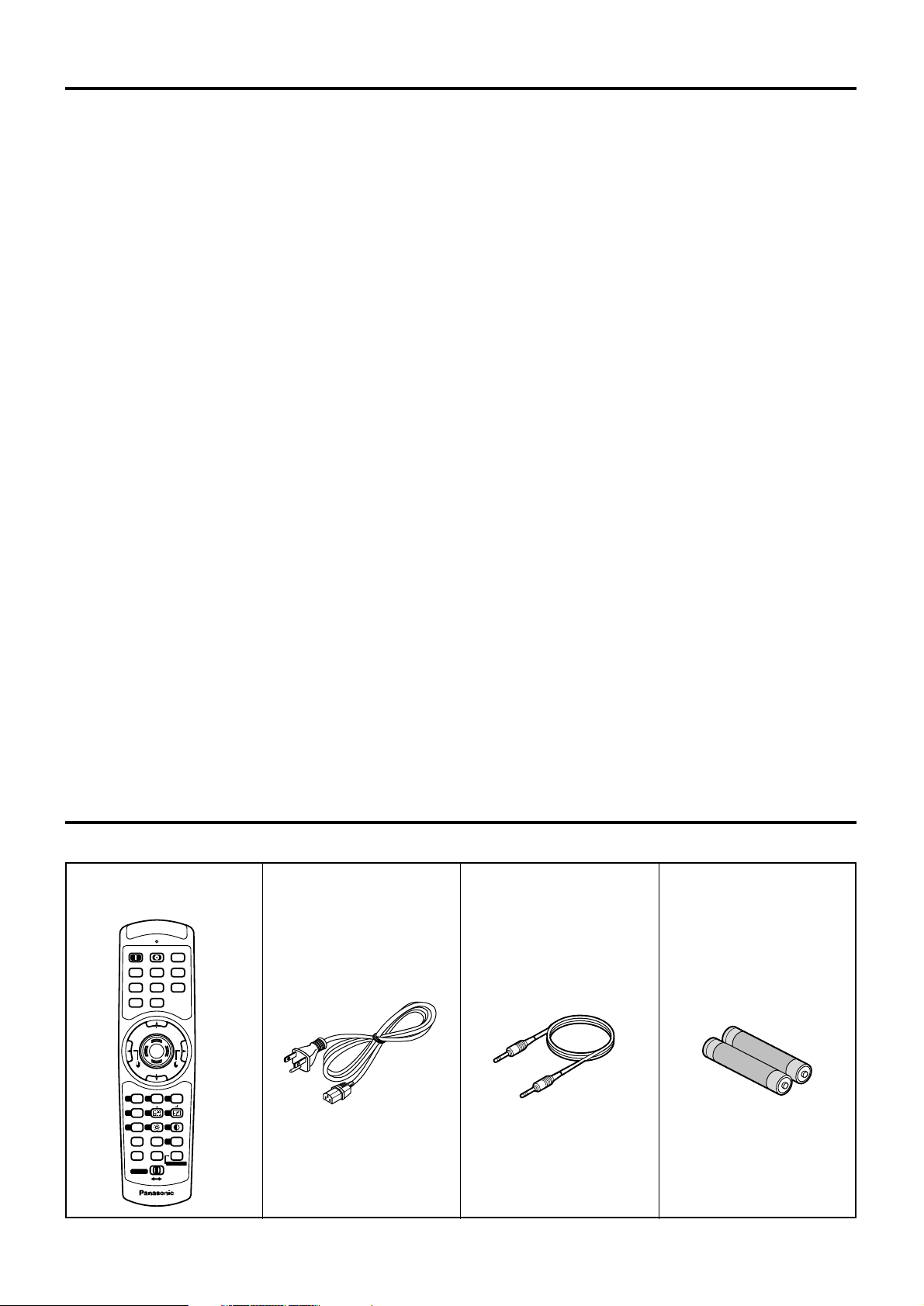
Check that all of the accessories shown below have been included with your projector.
Remote control unit
[N2QAGB000024 x 1]
POWER
ON OFF
RGB1RGB
2
AUX
MENU
STD
LENS
OSD
1
4
7
2
5
8
3
6
9
0
NEXT
USER
LIGHT
ID ALL
ASPECT
ID SET
Projector
Computer
Numetric
BRIGHT
CONTRAST
ON SCREEN
SYSTEM
SEL
FUNC
1
D.ZOOM
ENTER
PAGE UP
PAGE DOWN
VIDEO
SHUT
S-
VIDEO
FREEZE
SHUTTER
AUTO
SETUP
LASER ON/OFF
Power cord
[K2CF3EH00001 x 1]
Wired cable for remote control
[15m (49'3"),
K1EA03NA0001 x 1]
Battery for remote control
unit (AA)
[R03NPA/2ST x 1]
Do not look into the lens while the projector is being used.
•
Strong light is emitted from the projector’s lens. If you look directly into this light, it can hurt and damage your eyes.
Do not bring your hands or other objects close to the air outlet port.
•
Heated air comes out of the air outlet port. Do not bring your hands or face, or objects which cannot withstand heat.
Do not use the old lamp unit.
• The lamp section may break.
Replacement of the lamp unit should only be carried out after it has completely cooled
off, otherwise burns may result.
Disconnect the power cord plug from the wall outlet as a safety precaution before
carrying out any cleaning.
• Electric shocks can result if this is not done.
Ask an Authorized Service Center to clean inside the projector at least once a year.
• If dust is left to build up inside the projector without being cleaned out, it can result in fire or problems with
operation.
• It is a good idea to clean the inside of the projector before the season for humid weather arrives. Ask your
nearest Authorized Service Center to clean the projector when required. Please discuss with the Authorized
Service Center regarding cleaning costs.
Do not reach for the openings beside the optical lens, during horizontal or vertical
movements of the lens there is a injury hazard.
An effort to keep our environment clean, Please bring the non repairable unit your Dealer
or a Recycling Company.
Page 8

8
Precautions on handling
Precautions on transport
The projection lens is susceptible to vibrations and
impacts. Be sure to always remove the lens during
transport.
Precautions on installation
Be sure to observe the following precautions when
installing the product.
Avoid installing the product in a place
exposed to vibrations or impacts
.
If the projector is installed in a place where
vibrations are transmitted from a source of
driving power and others or mounted in a car or
a vessel, vibrations or impacts may be
transmitted to the product to damage the internal
parts, causing failure. Install the product in a
place free from vibrations and impacts.
Do not install the projector near highvoltage power lines or power sources.
The product may be exposed to interference if it
is installed in the vicinity of high-voltage electrical
power lines or power sources.
Do not place the projector on a vinyl
sheet or carpet.
If a vinyl sheet sucked up and blocks the air filter
intake port, the internal temperature of the
projector may increase, which triggers the
protection circuit, turning off the power.
Be sure to ask a specialized
technician when to install the
product to a ceiling.
If the product is to be installed hanging from the
ceiling, purchase an optional hanging attachment
(for high ceiling: Model No. ET-PKD75) (for low
ceiling: Model No. ET-PKD75S) and call a
specialized technician for installation.
Do not place the projector over 2 700 m
(8881.5') above sea level. When using it
over 1 400 m (4605.3') above sea level, set
the “Fan Control”, described on page 78,
to “HIGHLAND”.
Otherwise the life of the product may be shortened.
Precautions on use
To view clear images:
• The audience cannot enjoy high-contrast and
clear images if outside light or the illumination
interferes the screen surface.Draw window
curtains or blinds, turn off the lightings near the
screen or take other proper measures.
• In rare cases, wafture can occur on the screen
affected by the warm air from the exhaust port
depending on the environment.
Do not touch the surface of the
projection lens with bare hand.
If fingerprints or stains are left on the projection
lens surface, they are magnified and projected
on the screen. Keep your hands away from the
lens. Cover the lens with the supplied lens cap
when the projector is not used.
Screen
If the screen has stains, flaws or discoloration,
clear images cannot be viewed. When handling
the screen, be careful not to apply volatile
substances or leave flaws or stains on the screen.
Lamp
A mercury lamp with high internal pressure is used
for the light source of this product. A high-pressure
mercury lamp has the following characteristics:
• It may burst with a loud sound or end its life
cycle by not illuminating because of given
impacts, flaws, or deterioration due to used
hours.
• The life cycle of a mercury lamp varies according
to the individual difference or conditions of use.
In particular, turning the power on and off
frequently and/or repeatedly will greatly affect
the life cycle.
• In rare cases, it may burst shortly after the first
lighting.
• The possibility of burst increases when the lamp
is used beyond the replacement time.
Disposal
To discard the product, call the dealer or a specialized
dealer.
Cleaning and maintenance
Be sure to remove the power cord plug from the receptacle before cleaning.
Use soft and dry cloth to clean the cabinet
If stains are hard to remove, use a cloth dampened with a kitchen detergent solution (neutral) and squeezed
to wipe the cabinet and finish with a dry cloth. If a chemical wipe is used, follow its instructions.
Do not clean the lens surface with fuzzy or dusty cloth.
If dust adheres to the lens, it will be magnified and projected on the screen.
Use a soft and clean cloth to wipe off dust.
Page 9
9
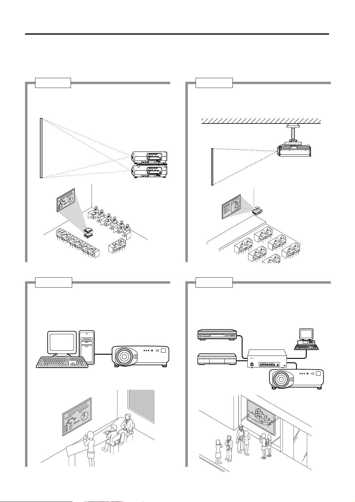
The projector is provided with a number of terminals and optional accessories to enable various system expansions.
Both input and output are provided to all terminals on the main unit.
The following are some examples of system expansion:
Examples of system expansion
System 1
Stacking two projectors with the
stacking brackets can double the
picture brightness.
System 3
PC equipped with a DVI-D input module (an
optional item) can be attached to the
projector for computer image viewing
(Realization of high-resolution picture.)
System 2
The optional high- or low-ceiling mount
bracket flexibly fits the projector in
individual site conditions.
System 4
Connection of a signal selector enables to
feed a variety of video sources to the
projector.
OFF
O
F
F
POWER
O
N
INPUT SE
LECT
1
2
3
45
6
VP
ON/OFF
S
i
g
n
a
l
S
e
l
e
c
t
o
r
T
W
-
S
W
S
Digital broadcasting tuner
or DVD player
Control PC
Signal selector
(Option)
Video deck
Page 10
10
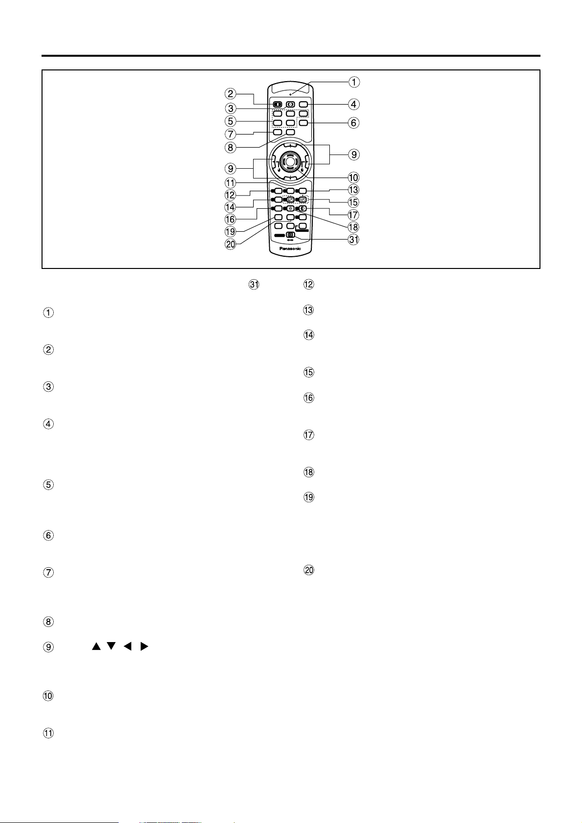
Name and function of parts
< When the operation mode selector is
set to Projector >
Remote control operation indicator lamp
The lamp flashes when any remote control button
is pressed.
POWER ON button (page 39)
Turns on the power if the MAIN POWER has been
put to the “l” position.
POWER OFF button (page 40)
Turns off the power if the MAIN POWER has been
put to the “l” position.
AUTO SET UP button (page 43)
Pressing this button while projecting an image
automatically corrects the picture positioning on the
screen. While the auto setup feature is active, a
message “PROGRESS...” appears on the screen.
Input selector (RGB1, RGB2, AUX, VIDEO,
S-VIDEO) button
Use to toggle through the RGB1, RGB2, AUX
(module input), VIDEO and S-VIDEO input ports.
SHUTTER button (page 48)
Press this button to black out the image
temporarily.
MENU button (page 50)
Displays and clears the Main Menu. It can also
return to the previous screen when the menu is
displayed.
FREEZE button (page 48)
Press this button to freeze the image temporarily.
Arrow buttons (page 50)
Use these buttons to select an item on the menu
screen, change setting and adjust the level.
Also use them to enter the “SECURITY” password.
ENTER button (page 50)
Press this button to enter your menu selection or to
run function.
ON SCREEN button
This button turns on and off the on-screen
indication function.
Standard (STD) button (page 50)
Press this button to restore the default factory setting
.
SYSTEM SELECTOR button (page 69)
System switching can be done.
Function 1 (FUNC1) button (page 80)
This button can control the functions set in
“FUNC1” of the “Option” screen from Main Menu.
Digital Zoom (- D.ZOOM +) buttons (page 48)
Any portion of the picture can be zoomed in.
LENS button (page 41)
Switches to the mode of projection lens
adjustment.
CONTRAST button (page 52)
Switches to the mode of image contrast
adjustment.
BRIGHT button (page 52)
Switches to the mode of black level adjustment.
NEXT button
When multiple signal selectors are connected to
the main unit in the system, this button specifies
the second signal selector or beyond. With the ID
set button pressed, every press on the button will
change the value in the ten’s place.
ASPECT button
Switches the image aspect ratio to 4:3, 16:9.
Remote control
POWER
ON OFF
RGB1RGB
2
AUX
MENU
STD
LENS
OSD
1
4
7
2
5
8
3
6
9
0
NEXT
USER
LIGHT
ID ALL
ASPECT
ID SET
Projector
Computer
Numetric
BRIGHT
CONTRAST
ON SCREEN
SYSTEM
SEL
FUNC
1
D.ZOOM
ENTER
PAGE UP
PAGE DOWN
VIDEO
SHUT
S-
VIDEO
FREEZE
SHUTTER
AUTO
SETUP
LASER ON/OFF
Page 11
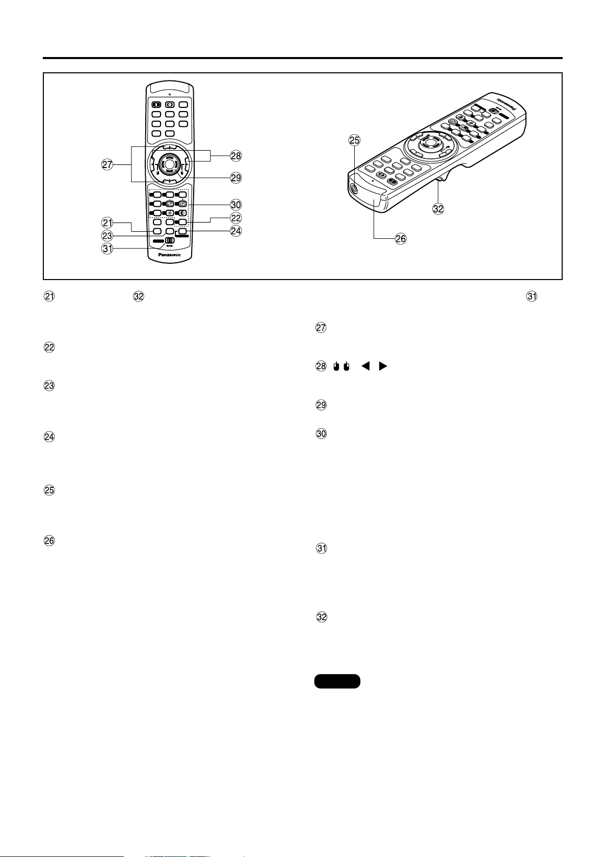
11
LIGHT button ( Click button)
When this button is pressed, the remote control
button light is turned on.The light goes off about 30
seconds after you stop remote control operation.
USER button
Displays the sub-memory screen of the signal
registration.
ID ALL button (pages 16,71)
When two or more main units are used in the
system, this button switches to the mode to control
them simultaneously with a single remote control.
ID SET button (pages 16,71)
When two or more main units are used in the
system, this button specifies the ID of the remote
control.
Remote control wired terminal (page 17)
To use the wired output terminal, connect the
remote control and the main unit with the supplied
cable.
Remote control transmitter window
Operate the remote control aiming at the remote
control receiver window on the main unit.
ON OFF
<When the operation mode selector is
set to Computer>
PAGE UP/PAGE DOWN buttons
These buttons correspond to the PAGE UP/PAGE
DOWN buttons on PC's keyboard.
( ) buttons
These buttons correspond to the left and right
mouse buttons.
ENTER button
Moves the mouse cursor.
Numeric (0-9) buttons
In a system that uses two or more units of this
projector or in a system that connects to an
optional signal selector, these buttons specify a
particular projector unit or the input of the signal
selector. They are also used to input the ID
number when selecting the ID and to enter the
password when the password for service
personnel needs to be entered.
Operation mode selector (Computer/Numeric,
Projector) switch (page 17)
Put this selector to the right position to control the
projector and to the left position to control the PC
or use numeric buttons.
Click button (page 17)
This button corresponds to the left mouse button
when the operation mode is switched to the
Computer position.
• To use the remote control as a mouse,
please purchase an optional wireless
mouse receiver (model No.: ET-RMRC2).
• The AUX button to switch the input is
disabled when an optional input module is
not connected.
Note
RGB1RGB
VIDEO
MENU
STD
1
FUNC
4
LENS
7
NEXT
LIGHT
Computer
Numetric
POWER
AUTO
SETUP
AUX
2
SHUTTER
S-
VIDEO
SHUT
FREEZE
PAGE UP
ENTER
PAGE DOWN
ON SCREEN
SYSTEM
OSD
3
2
SEL
D.ZOOM
6
5
1
CONTRAST
BRIGHT
9
8
USER
ASPECT
0
ID ALL
ID SET
LASER ON/OFF
Projector
P
U
T
O
E
T
U
A
E
Z
SHUT
E
E
R
U
A
F
R
HUTTER
S
E
W
O
P
O
E
D
I
V
-
2
B
G
R
B
NO
O
F
S
PAGE
VIDEO
1
G
R
X
S
F
M
E
T
SEL
S
Y
S
N
E
N
W
O
D
E
G
R
A
P
ENTE
P
U
E
G
A
P
MENU
PAGE
r
o
t
F
F
c
O
/
je
N
T
O
ro
E
R
P
E
S
S
ID
A
L
L
L
USER
A
tric
ID
e
0
T
S
A
R
T
N
9
O
C
6
RIGHT
B
D.ZOOM
3
D
5
S
O
C
N
E
U
R
C
2
S
N
D
O
T
S
1
m
u
N
ASPECT
T
H
Computer
IG
L
T
X
E
N
8
S
N
E
L
7
1
F
4
Page 12
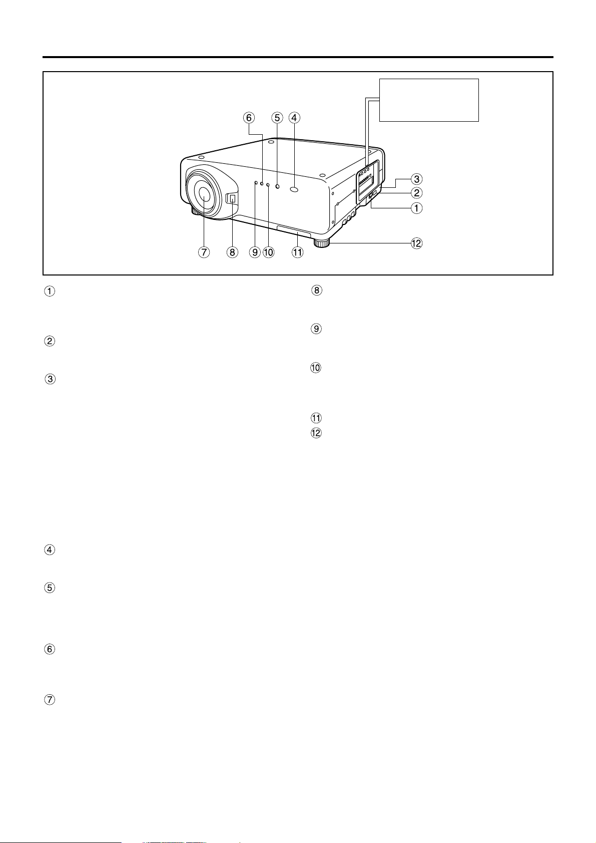
12
Side-mounted
connection terminals
(page 14)
AC IN terminal (page 39)
Connect the supplied line power cord into this
receptacle.
Do not connect any other cable to this socket.
MAIN POWER switch (page 39)
Use this switch to turn on “I” and off “o” the
commercial line power applied to the projector.
Burglar lock
Attach a commercial burglar prevention cable (e.g.,
from Kensington) to this lock port. It is compatible
with the Micro Save Security System from
Kensington. This security lock is compatible with the
Microsaver Security System from Kensington.
Contact details for this company are given below.
Kensington Technology Group ACCO Brands Inc.
2885 Campus Drive San Mateo, CA94403
Tel (650)572-2700
Fax (650)572-9675
http://www.kensington.com/
http://www.gravis.com/
Remote control receiver window (front) (page 15)
This window receives the signal beam emitted from
the remote control.
Power indicator lamp (page 39)
The lamp lights in red when the MAIN POWER
switch is turned to “I” (on). It turns to green when
the POWER ON button of the remote control or the
main unit is pressed.
LAMP1 monitor (page 98)
This lamp lights up when the time to replace lamp
unit 1 is reached. It also blinks if something
unusual occurs in the lamp circuit.
Projection lens (optional)
Lens for projecting images on the screen.
Projection lens cover lock button
This button toggles between lock and unlock of the
detachable cover for the projection lens (optional).
Temperature monitor (TEMP) (page 98)
Lighting or blinking of this lamp indicates an
abnormal condition of the internal temperature.
LAMP2 monitor (page 98)
This lamp lights up when the time to replace lamp
unit 2 is reached. It also blinks if something
unusual occurs in the lamp circuit.
Air filter (page 99)
Level-adjusting feet (page 18)
Use these feet to adjust the tilt of the projector.
(Leveling feet are provided at the front and rear,
right and left.)
Name and function of parts
Front and side of the projector
Page 13
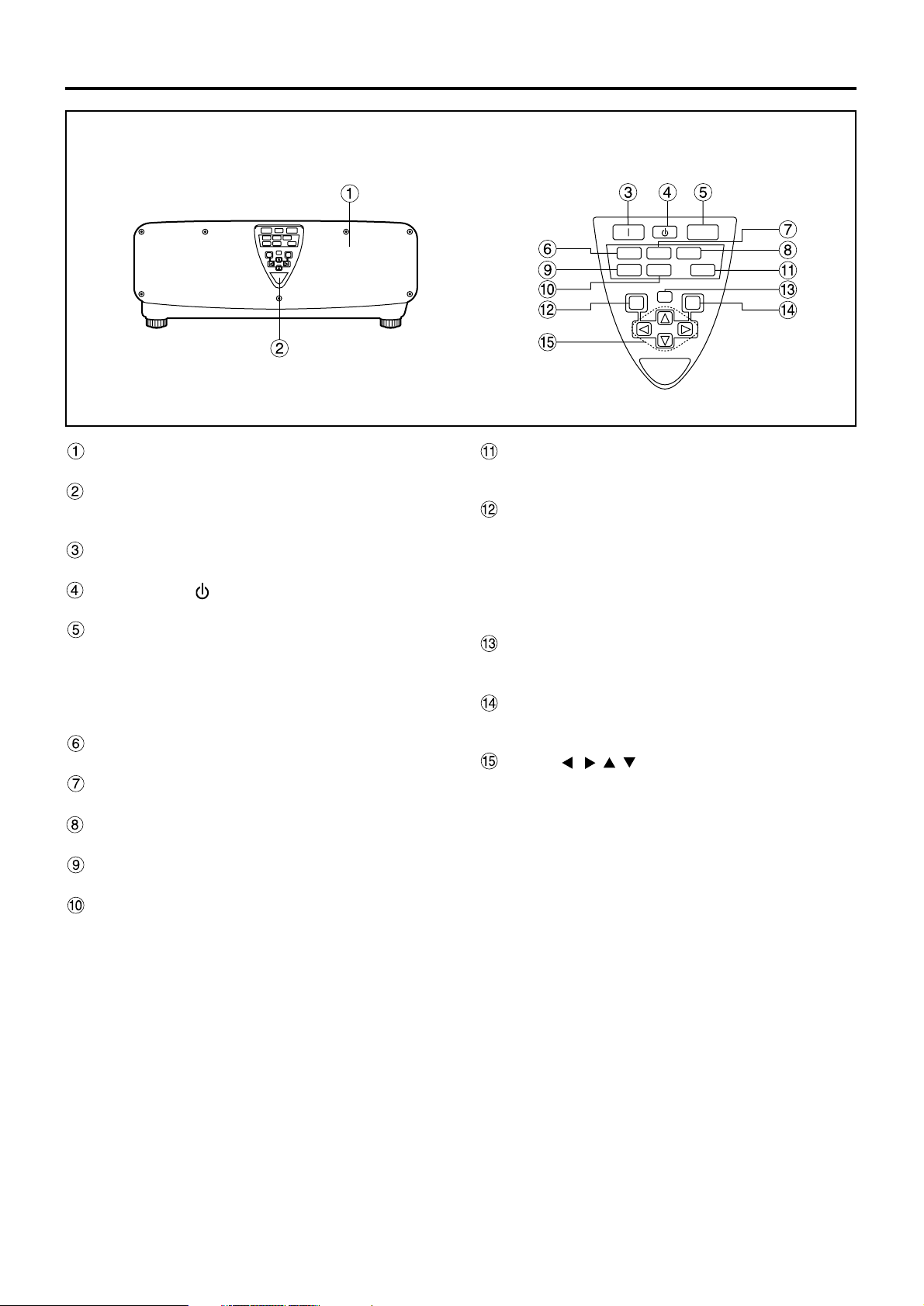
13
Lamp unit cover
The lamp unit is housed.
Remote control receiver window (rear) (page 15)
This also receives the signal beam coming from
the remote control.
POWER ON (I) button (page 39)
Turns on the power.
POWER OFF ( ) button (page 40)
Turns off the power.
AUTO SETUP button (page 43)
Pressing this button while projecting an image
automatically corrects the picture positioning on
the screen. While the auto setup feature is active,
a message “EXECUTING...” appears on the
screen.
RGB1 button (page 39)
Switches to RGB1 input.
RGB2 button (page 39)
Switches to RGB2 input.
AUX button (page 39)
Switches to optional input module input.
VIDEO button (page 39)
Switches to video input.
S-VIDEO button (page 39)
Switches to S-VIDEO input.
SHUTTER button (page 48)
Press this button to black out the image
temporarily.
MENU button (pages 50 and 88–89)
Displays and clears the Main Menu. It can also
return to the previous screen when the menu is
displayed.
Menus can be displayed by holding down the
MENU button for at least 3 seconds while the onscreen indication function is OFF.
LENS button (page 41)
Switches to the adjustment mode for lens focus,
zoom and shift (position).
ENTER button (page 50)
Press this button to enter your menu selection or to
run function.
Arrow ( ) buttons (page 50)
Use to select an item on the menu screen, change
setting and adjust the level.
Also use them to enter the “SECURITY” password.
Rear view of the main unit Controls on rear panel
AUTO
SETUP
RGB 1
VIDEO
MENU
ENTER
LENS
S-VIDEO
SHUTTER
RGB 2
AUX
Page 14
14
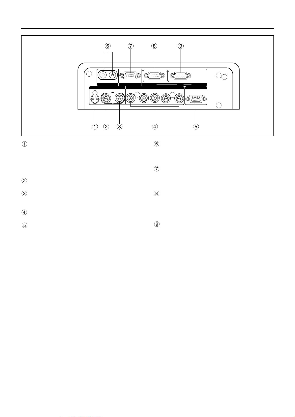
S-VIDEO IN terminal (pages 24 and 25)
An input terminal for S-video signals
(MIN4-pin DIN).
This terminal complies with S1 signals and
automatically toggles between 16:9 and 4:3
according to the size of input signals.
VIDEO IN terminal (page 25)
An input terminal for video signals. (BNC)
VIDEO OUT terminal (page 25)
An output terminal (active through) for video
signals. (BNC)
RGB (YPBPR)1 input terminal (pages 26, 27)
A terminal to input RGB or YPBPR signals (BNC).
RGB (YPBPR)2 input terminal (page 26)
A terminal to input RGB or YPBPR signals (D-SUB
15-pin female).
REMOTE1 lN/OUT terminal (page 17)
When two or more main units are used in the
system, they can be connected and controlled with
a wired remote control cable (M3 jack).
REMOTE2 terminal (page 84)
The user can remotely control the main unit by
using an external control circuit to this terminal
(D-SUB 9-pin female).
SERIAL IN terminal (pages 25–27, 74, 82, 83)
This terminal is an RS-232C/RS-422 compliant
input terminal (switching necessary) to connect a
PC and to externally control the main unit
(D-SUB 9-pin female).
SERIAL OUT terminal (pages 26, 27, 74, 82, 83)
This terminal is an RS-232C/RS-422 compliant
output terminal (switching necessary) to supply
signals given to the serial input terminal
(D-SUB 9-pin male).
SERIAL
S-VIDEO
RGB 2 IN
VIDEO
REMOTE 1
RGB 1 IN
IN
IN
IN
OUT
OUT
OUT
SYNC/HD VDB/PBG/Y
REMOTE 2
R/PR
RS-232C (G) / RS-422 (R)RS-232C (G) / RS-422 (R)
IN
Side-mounted
connection terminals
Name and function of parts
Page 15
15
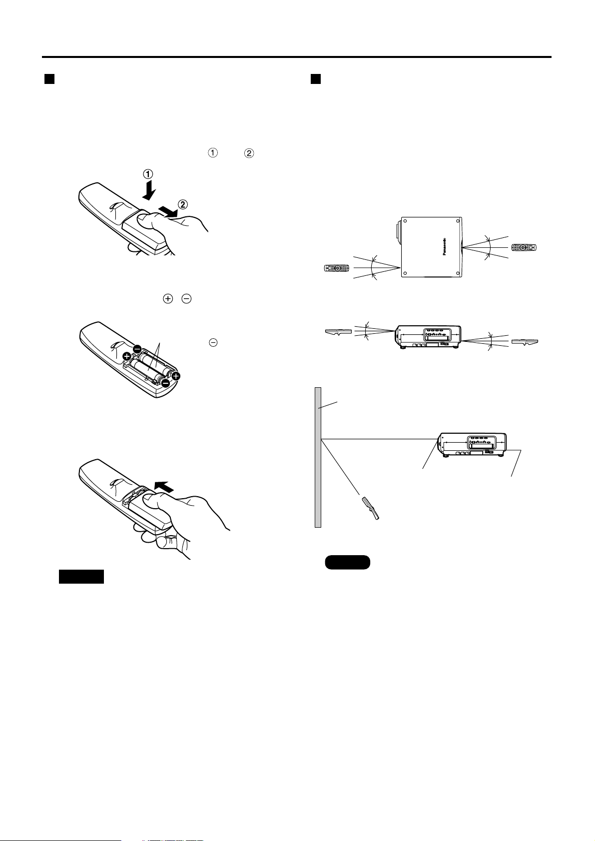
Loading dry cells
When loading supplied AA dry cells into the battery
compartment of the remote control, make sure that
their polarities are correct.
1. Open battery compartment lid.
Open the lid in the order of steps and .
2. Insert the dry cells.
Into battery compartment, with their polarities
orientated as indicated ( , )in the
compartment.
3. Close the battery compartment lid.
Replace the battery compartment lid over the
compartment and slide until it clicks.
Effective range of remote control operation
The remote control should normally be aimed at either
the front or rear remote control receiver window on the
projector (figure 1). Otherwise, it may also be aimed at
the screen, which will reflect commands back to the
projector's front receiver window as illustrated in figure 2.
The effective control range is approx. 7 meters from
the beam receiver on the front or rear.
• Do not drop the remote control unit.
• Do not expose remote control unit to
any liquid.
• Do not use NiCd batteries.
Attention
• When the remote control is aimed at
the screen, the effective control range
may be reduced due to the optical loss
by screen reflection.
• The remote control may not function
properly if an object is in the light path.
• The remote control receiver may not
function properly in intense ambient
light such as fluorescent lamps.
Carefully site the projector so its
remote control receiver windows will
not be directly exposed to intense light.
Supplied AA dry cells
(insert the side first).
(Front) (Rear)
[Top view]
Remote
control
30˚
30˚
30˚
30˚
[Side view]
15˚
15˚
15˚
15˚
Remote
control
Remote
control
Remote
control
Screen
Projector
Remote control
receiver window
(front)
Remote control
receiver window
(rear)
Remote control
Using the remote control unit
Note
Figure 2
Figure 1
Page 16

16
Every projector has its ID number and the ID number of the controlling projector must be set to the remote control
in advance so that the user can operate the remote control. The ID number of the projector is set to “ALL” on
shipping, and use the ID ALL button of the remote control when using only a single projector.
Procedure of ID setting
Change the position of the operation mode selector switch to “Computer”.
Press the ID SET button, and within five seconds, use the NEXT button to set the
number of the tens digit in the ID number, which is already set in the projector, and
then use one of the numeric (0-9) buttons to set the number of the units digit.
Change the position of the operation mode selector switch to “Projector”.
However, if the ID ALL button is pressed, the projector can be controlled regardless of the ID number of the
projector (simultaneous control mode).
Using the remote control unit
Setting projector ID number to remote control
• Do not press the ID SET button accidentally or carelessly because the ID number on the remote
control can be set even when no projector is around.
If the ID SET button is pressed, the ID number goes back to the one set before pressing the ID
SET button unless the NEXT button and a numeric button are pressed within five seconds after
the ID SET button is pressed.
• Your specified ID number is stored in the remote control unit unless another one is specified later.
However, the stored ID will be erased if the batteries of the remote control are left exhausted.
When the dry cells are replaced, set the same ID number again.
Attention
Page 17
17
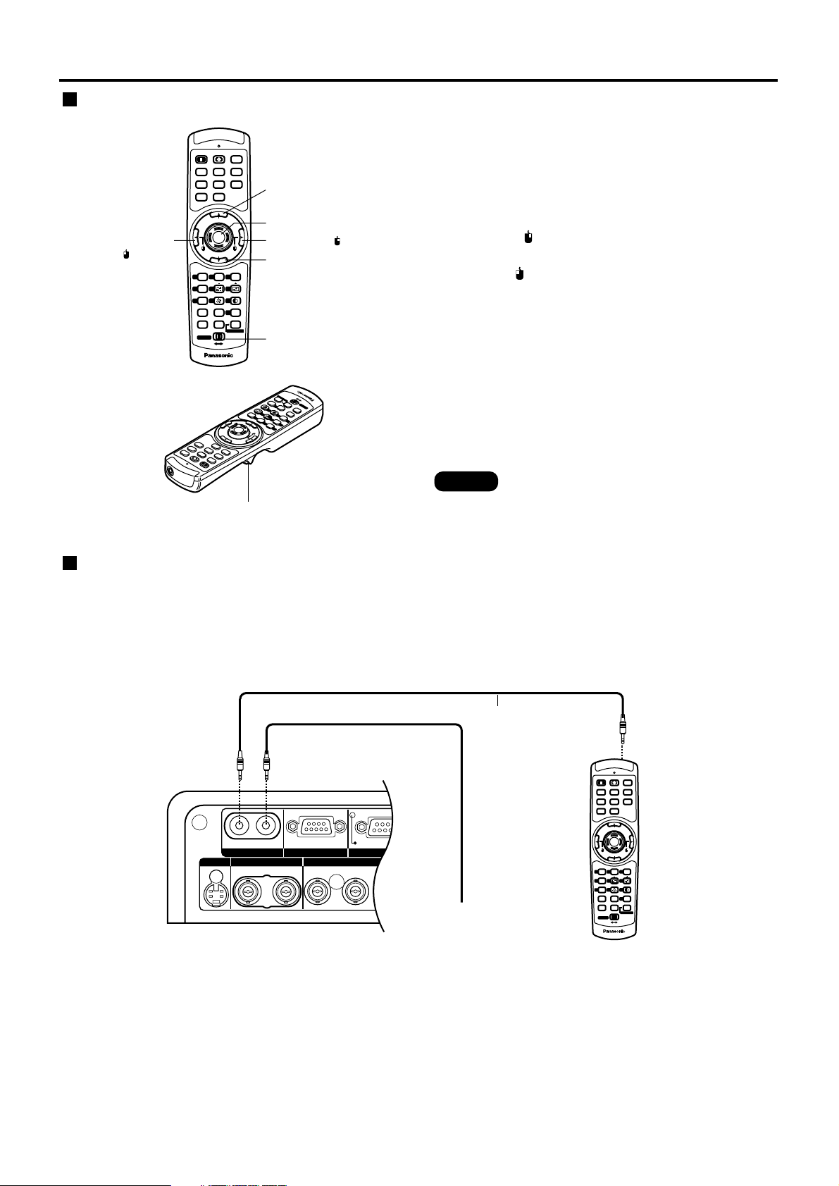
Using the remote control as a PC mouse
Operation mode selector switch
Put the knob to the Computer position.
• ENTER button
Pressing the front, rear, left and right edges of the
button moves the mouse cursor up, down, left and
right.
• Right click ( ) button
This button can be used as the right mouse button.
• Left click ( ) button
This button can be used as the left mouse button.
• PAGE UP button
This button can be used as the Page Up button on the
PC keyboard.
• PAGE DOWN button
This button can be used as the Page Down button on
the PC keyboard.
• Click button
This button can be used as the left mouse button.
POWER
ON OFF
RGB1RGB
2
AUX
MENU
STD
LENS
OSD
1
4
7
2
5
8
3
6
9
0
NEXT
USER
LIGHT
ID ALL
ASPECT
ID SET
Projector
Computer
Numetric
BRIGHT
CONTRAST
ON SCREEN
SYSTEM
SEL
FUNC
1
D.ZOOM
ENTER
PAGE UP
PAGE DOWN
VIDEO
SHUT
S-
VIDEO
FREEZE
SHUTTER
AUTO
SETUP
LASER ON/OFF
PAGE DOWN button
Operation mode
selector switch
ENTER button
Right click ( ) button
PAGE UP button
Left click
( ) button
P
A
G
E
DOWN
LASE
R O
N/OFF
P
A
G
E
P
A
G
E
P
O
W
E
R
ON
OFF
R
G
B
1
R
G
B
2
AUX
M
E
N
U
ENTER
P
A
G
E
UP
V
I
D
E
O
S
H
U
T
S-
V
I
D
E
O
F
R
E
E
Z
E
S
H
U
T
T
E
R
A
U
T
O
SE
TU
P
STD
LENS
OSD
1
4
7
2
5
8
3
6
9
0
NEXT
U
S
E
R
LIGHT
ID ALL
I
D
S
E
T
P
r
o
j
e
c
t
o
r
C
o
m
p
u
t
e
r
N
u
m
e
tr
ic
B
R
IG
H
T
C
O
N
T
R
A
S
T
O
N
S
C
R
E
E
N
S
Y
S
T
E
M
S
E
L
F
U
N
C
1
D
.Z
O
O
M
A
S
P
E
C
T
Click button
• To use the remote control as a mouse,
please purchase an optional wireless
mouse receiver (model No.: ET-RMRC2).
When multiple main units are connected in the system,
connect the units with the supplied remote control
cable to simultaneously control the multiple main units
with a single remote control unit through the
SERIAL
S-VIDEO
RGB 2 IN / RGB 1 OUT
VIDEO
REMOTE 1
RGB 1 IN
IN
IN
IN
OUT
OUT
OUT
SYNC/HD VDB/PBG/Y
REMOTE 2
R/PR
RS-232C (G) / RS-422 (R)RS-232C (G) / RS-422 (R)
IN
POWER
ON OFF
RGB1RGB
2
AUX
MENU
STD
LENS
OSD
1
4
7
2
5
8
3
6
9
0
NEXT
USER
LIGHT
ID ALL
ASPECT
ID SET
Projector
Computer
Numetric
BRIGHT
CONTRAST
ON SCREEN
SYSTEM
SEL
FUNC
1
D.ZOOM
ENTER
PAGE UP
PAGE DOWN
VIDEO
SHUT
S-
VIDEO
FREEZE
SHUTTER
AUTO
SETUP
LASER ON/OFF
Side-mounted terminals
Connect to the
secondary projector
Remote control
Remote control cable
(supplied)
Using a wired remote control
REMOTE1 IN/OUT terminal. It is effective to use the
wired remote control in the environment in which an
obstacle stands in the light path or where devices are
susceptible to outside light.
Note
Page 18
18
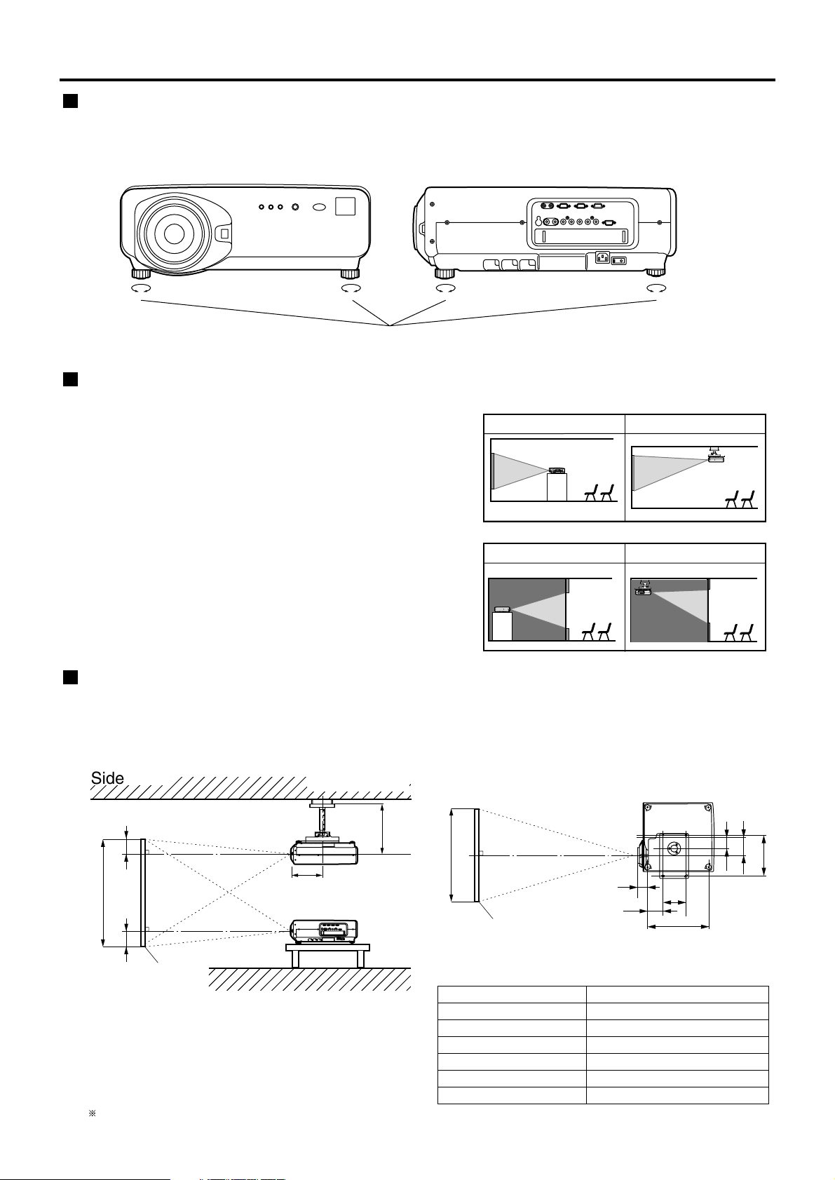
Projection scheme
This projector can use any of the four projection
schemes shown at right. Select the scheme that best
suits your particular installation location. Select the
most suitable scheme to the situation of your location.
Use the OPTION menu on the menu screen to choose
the desired projection scheme. (Refer to page 72)
Rear projection
Front projection
Table standing
Ceiling mount
Table standing
Ceiling mount
(Default position)
< Front > < Side >
Leveling feet
Installation
Adjusting the leveling feet
The four leveling feet mounted at the bottom of the projector are level-adjustable (0 mm–33 mm) which can be used
when the floor surface is not horizontal.
Installation geometry
When planning the projector and screen geometry, refer to the figures below and the information on the next page
for reference. After the projector is roughly positioned, picture size and vertical picture positioning can be finely
adjusted with the powered zoom lens and lens shifting mechanism.
H
SH
L
L
H
;
;
Side view
When optional ceiling
mount bracket (ET-PKD75)
Screen
(unit: mm/inch)
438-558
(17.2"-21.9")
237
(9.3")
L
SW
314
86
140
175
468
117
L1
Top view
Screen
(unit: mm/inch)
(18.4")
(5.5")
(12.3")
(3.4")
(6.9")
(4.6")
L : Projection distance
SH : Height of the image
SW : Image width
H : Vertical distance between the lens center
level and the bottom edge of the projected
image
For PT-D7700U: H = 0 to SH
For PT-DW7000U: H = -0.18 x SH to 1.18 x SH
Lens Dimension of L1 (Approx.)
ET-D75LE1 102 (4")
ET-D75LE2 86.5 (3.4")
ET-D75LE3 90 (3.5")
ET-D75LE4 113.9 (4.5")
ET-D75LE5 190 (7.5")
ET-D75LE8 242 (9.5")
Page 19
19
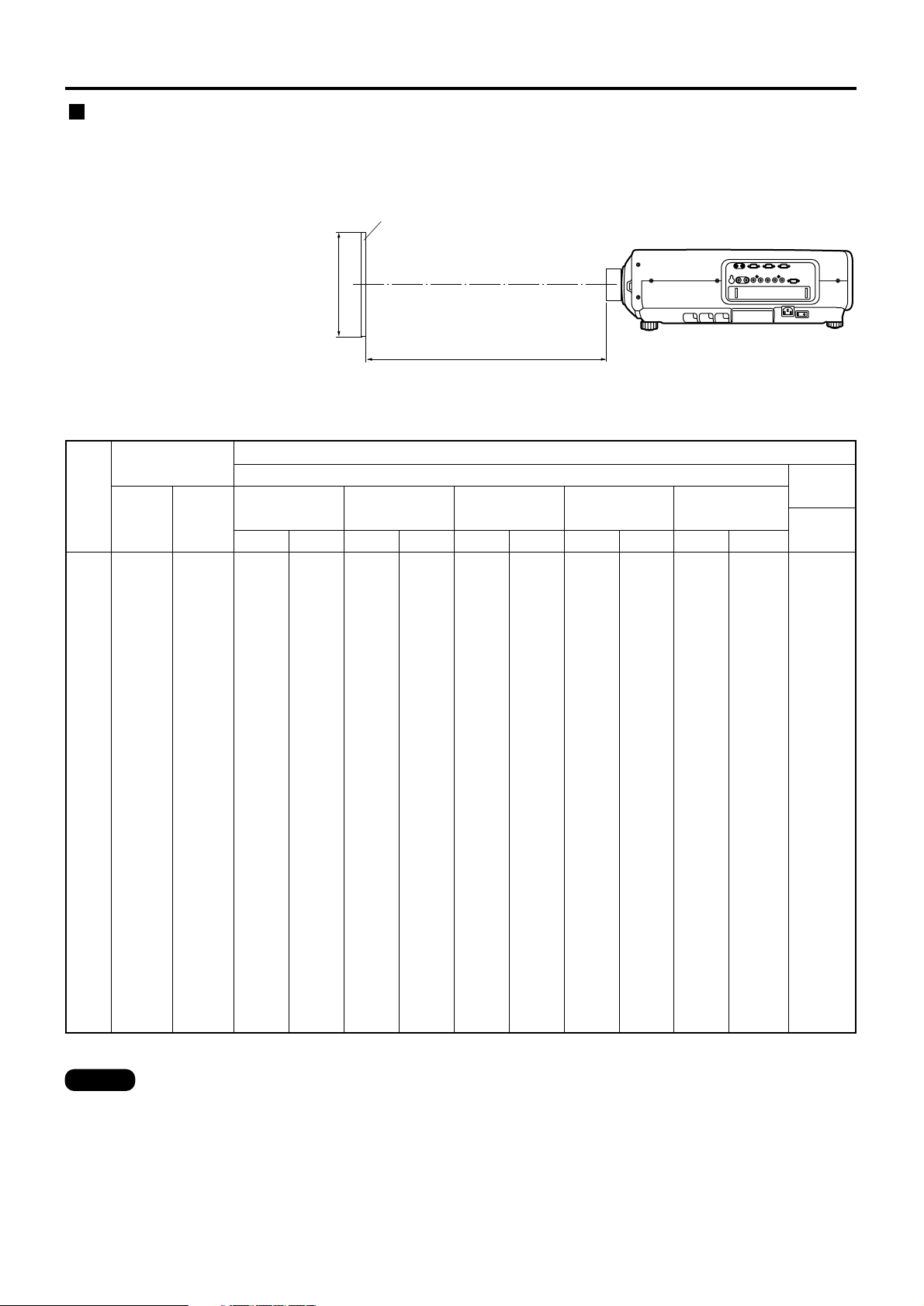
L : Projection distance
SH : Effective screen height
L
SH
Screen
Projection distances by the type of projection lenses (for PT-D7700U)
• For the screen aspect ratio of 4:3 Units: m (feet/inches)
• The projection distances listed here involve an error of ±5%.
• Keystone distortions are corrected in the way the screen size becomes smaller than the original one.
Projection distances by the type of projection lenses (optional)
Every type of optional projection lenses has a different projection distance to achieve the same screen size. Select
and purchase a projection lens most suitable to the size of your location referring to the following tables and the
projection distances by the type of projection lenses on the next page.
Screen
size
(inch)
Screen
dimensions
70
80
90
100
120
150
200
250
300
350
400
500
600
1.066
(3'6")
1.219
(4'0")
1.371
(4'6")
1.524
(5'0")
1.828
(6'0")
2.286
(7'6")
3.048
(10'0")
3.810
(12'6")
4.572
(15'0")
5.334
(17'6")
6.096
(20'0")
7.620
(25'0")
9.144
(30'0")
1.422
(4'8")
1.625
(5'4")
1.828
(6'0")
2.032
(6'8")
2.438
(8'0")
3.048
(10'0")
4.064
(13'4")
5.080
(16'8")
6.096
(20'0")
7.112
(23'4")
8.129
(26'8")
10.160
(33'4")
12.192
(40'0")
Effective
width
(SW)
1.02
1.18
1.34
1.50
1.81
2.29
3.08
3.87
4.66
(3'4'')
(3'10'')
(4'4'')
(4'11'')
(5'11'')
(7'6'')
(10'1'')
(12'8'')
(15'3'')
-----
-----
-----
-----
11.37
13.01
14.65
16.29
19.57
24.49
32.69
40.88
49.08
57.28
65.47
81.87
98.26
(37'3'')
(42'8'')
(48')
(53'5'')
(64'2'')
(80'4'')
(107'3'')
(134'1'')
(161')
(187'11'')
(214'9'')
(268'7'')
(322'4'')
7.10
8.13
9.16
10.19
12.26
15.35
20.50
25.66
30.81
35.97
41.12
51.43
61.74
(23'3'')
(26'8'')
(30')
(33'5'')
(40'2'')
(50'4'')
(67'3'')
(84'2'')
(101')
(118')
(134'10'')
(168'8'')
(202'6'')
7.09
8.13
9.16
10.19
12.25
15.34
20.50
25.65
30.81
35.96
41.12
51.42
61.73
(23'3'')
(26'8'')
(30')
(33'5'')
(40'2'')
(50'3'')
(67'3'')
(84'1'')
(101')
(117'11'')
(134'10'')
(168'8'')
(202'6'')
4.23
4.84
5.46
6.08
7.31
9.16
12.25
15.34
18.42
21.51
24.60
30.77
36.94
(13'10'')
(15'10'')
(17'10'')
(19'11'')
(23'11'')
(30')
(40'2'')
(50'3'')
(60'5'')
(70'6'')
(80'8'')
(100'11'')
(121'2'')
4.21
4.83
5.45
6.07
7.30
9.15
12.24
15.33
18.41
21.50
24.58
30.76
36.93
(13'9'')
(15'10'')
(17'10'')
(19'10'')
(23'11'')
(30')
(40'1'')
(50'3'')
(60'4'')
(70'6'')
(80'7'')
(100'11'')
(121'1'')
2.80
3.21
3.62
4.04
4.86
6.09
8.15
10.21
12.27
14.32
16.38
20.50
24.61
(9'2'')
(10'6'')
(11'10'')
(13'3'')
(15'11'')
(19'11'')
(26'8'')
(33'5'')
(40'3'')
(46'11'')
(53'8'')
(67'3'')
(80'8'')
2.77
3.18
3.59
4.00
4.82
6.05
8.10
10.15
12.19
14.24
16.29
20.39
24.49
(9'1'')
(10'5'')
(11'9'')
(13'1'')
(15'9'')
(19'10'')
(26'6'')
(33'3'')
(39'11'')
(46'8'')
(53'5'')
(66'10'')
(80'4'')
2.07
2.38
2.68
2.99
3.60
4.53
6.06
7.59
9.13
10.66
12.19
15.26
18.33
(6'9'')
(7'9'')
(8'9'')
(9'9'')
(11'9'')
(14'10'')
(19'10'')
(24'10'')
(29'11'')
(34'11'')
(39'11'')
(50')
(60'1'')
Minimum
Maximum
ET-D75LE1
(1.5-2.0 :1)
Minimum
Maximum
ET-D75LE2
(2.0-3.0 :1)
Minimum
Maximum
ET-D75LE3
(3.0-5.0 :1)
Minimum
Maximum
ET-D75LE4
(5.0-8.0 :1)
ET-D75LE5
(0.8 : 1)
Projection distance (L)
Zoom lens
Fixed-
focus lens
21.14
24.22
27.29
30.36
36.50
45.72
61.08
76.44
91.79
107.15
122.51
153.23
183.95
(69'4'')
(79'5'')
(89'6'')
(99'7'')
(119'9'')
(150')
(200'4'')
(250'9'')
(301'1'')
(351'6'')
(401'11'')
(502'8'')
(603'6'')
11.09
12.73
14.37
16.01
19.29
24.21
32.40
40.60
48.80
57.00
65.19
81.59
97.98
(36'4'')
(41'9'')
(47'1'')
(52'6'')
(63'3'')
(79'5'')
(106'3'')
(133'2'')
(160'1'')
(187')
(213'10'')
(267'8'')
(321'5'')
Minimum
Maximum
ET-D75LE8
(8.0-15.0 :1)
Effective
height
(SH)
Note
(Continued on next page)
Page 20
20
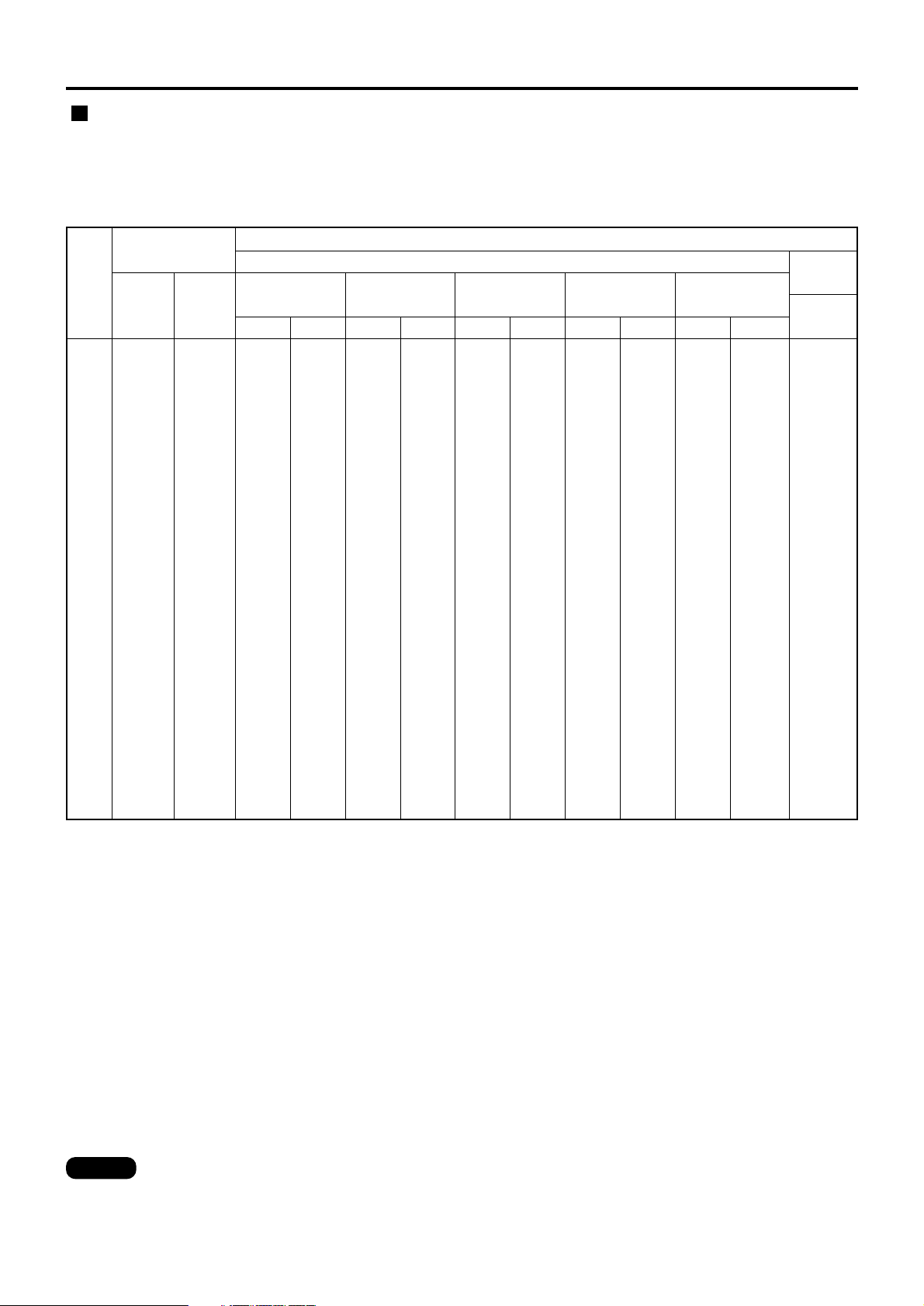
• The projection distances listed here involve an error of ±5%.
• Keystone distortions are corrected in the way the screen size becomes smaller than the original one.
Installation
Projection distances by the type of projection lenses
(optional) (continuing)
Projection distances by the type of projection lenses (for PT-D7700U)
• For the screen aspect ratio of 16:9 Units: m (feet/inches)
Note
Screen
size
(inch)
Screen
dimensions
70
80
90
100
120
150
200
250
300
350
400
500
600
0.871
(2'10")
0.996
(3'3")
1.120
(3'8")
1.245
(4'1")
1.494
(4'11")
1.868
(6'2")
2.491
(8'2")
3.113
(10'3")
3.736
(12'3")
4.358
(14'4")
4.981
(16'4")
6.226
(20'5")
7.472
(24'7")
1.549
(5'1")
1.771
(5'10")
1.992
(6'7")
2.214
(7'3")
2.657
(8'9")
3.321
(10'11")
4.428
(14'6")
5.535
(18'2")
6.641
(21'70")
7.748
(25'5")
8.855
(29'0")
11.069
(36'4")
13.282
(43'8")
Effective
width
(SW)
1.12
1.29
1.47
1.64
1.98
2.50
3.36
4.22
5.08
(3'8'')
(4'2'')
(4'9'')
(5'4'')
(6'5'')
(8'2'')
(11')
(13'10'')
(16'8'')
-----
-----
-----
-----
12.40
14.19
15.97
17.76
21.33
26.69
35.61
44.54
53.47
62.40
71.33
89.19
107.04
(40'8'')
(46'6'')
(52'4'')
(58'3'')
(69'11'')
(87'6'')
(116'9'')
(146'1'')
(175'5'')
(204'8'')
(234')
(292'7'')
(351'2'')
7.75
8.87
9.99
11.11
13.36
16.73
22.34
27.96
33.57
39.19
44.80
56.03
67.26
(25'5'')
(29'1'')
(32'9'')
(36'5'')
(43'9'')
(54'10'')
(73'3'')
(91'8'')
(110'1'')
(128'6'')
(146'11'')
(183'9'')
(220'8'')
7.74
8.86
9.99
11.11
13.35
16.72
22.34
27.95
33.57
39.18
44.80
56.03
67.26
(25'4'')
(29')
(32'9'')
(36'5'')
(43'9'')
(54'10'')
(73'3'')
(91'8'')
(110'1'')
(128'6'')
(146'11'')
(183'9'')
(220'8'')
4.61
5.28
5.96
6.63
7.97
9.99
13.35
16.71
20.08
23.44
26.80
33.53
40.25
(15'1'')
(17'3'')
(19'6'')
(21'9'')
(26'1'')
(32'9'')
(43'9'')
(54'9'')
(65'10'')
(76'10'')
(87'11'')
(110')
(132')
4.60
5.27
5.95
6.62
7.96
9.98
13.34
16.70
20.07
23.43
26.79
33.51
40.24
(15'1'')
(17'3'')
(19'6'')
(21'8'')
(26'1'')
(32'8'')
(43'9'')
(54'9'')
(65'10'')
(76'10'')
(87'10'')
(109'11'')
(132')
3.06
3.51
3.96
4.40
5.30
6.65
8.89
11.13
13.37
15.61
17.85
22.33
26.82
(10')
(11'6'')
(12'11'')
(14'5'')
(17'4'')
(21'9'')
(29'2'')
(36'6'')
(43'10'')
(51'2'')
(58'6'')
(73'3'')
(87'11'')
3.03
3.47
3.92
4.36
5.26
6.60
8.83
11.06
13.29
15.53
17.76
22.22
26.69
(9'11'')
(11'4'')
(12'10'')
(14'3'')
(17'3'')
(21'7'')
(28'11'')
(36'3'')
(43'7'')
(50'11'')
(58'3'')
(72'10'')
(87'6'')
2.26
2.60
2.93
3.27
3.93
4.94
6.61
8.28
9.95
11.62
13.29
16.63
19.97
(7'4'')
(8'6'')
(9'7'')
(10'8'')
(12'10'')
(16'2'')
(21'8'')
(27'1'')
(32'7'')
(38'1'')
(43'7'')
(54'6'')
(65'6'')
Minimum
Maximum
ET-D75LE1
(1.5-2.0 :1)
Minimum
Maximum
ET-D75LE2
(2.0-3.0 :1)
Minimum
Maximum
ET-D75LE3
(3.0-5.0 :1)
Minimum
Maximum
ET-D75LE4
(5.0-8.0 :1)
ET-D75LE5
(0.8 : 1)
Projection distance (L)
Zoom lens
Fixed-
focus lens
23.06
26.41
29.76
33.10
39.79
49.83
66.56
83.29
100.02
116.75
133.49
166.95
200.41
(75'7'')
(86'7'')
(97'7'')
(108'7'')
(130'6'')
(163'5'')
(218'4'')
(273'3'')
(328'1'')
(383')
(437'11'')
(547'8'')
(657'6'')
12.12
13.90
15.69
17.47
21.05
26.40
35.33
44.26
53.19
62.12
71.05
88.91
106.77
(39'9'')
(45'7'')
(51'5'')
(57'3'')
(69')
(86'7'')
(115'10'')
(145'2'')
(174'6'')
(203'9'')
(233'1'')
(291'8'')
(350'3'')
Minimum
Maximum
ET-D75LE8
(8.0-15.0 :1)
Effective
height
(SH)
Page 21

21
• The projection distances listed here involve an error of ±5%.
• Keystone distortions are corrected in the way the screen size becomes smaller than the original one.
Note
Projection distances by the type of projection lenses (for PT-DW7000U)
• For the screen aspect ratio of 16:9 Units: m (feet/inches)
Screen
size
(inch)
Screen
dimensions
70
80
90
100
120
150
200
250
300
350
400
500
600
0.871
(2'10")
0.996
(3'3")
1.120
(3'8")
1.245
(4'1")
1.494
(4'11")
1.868
(6'2")
2.491
(8'2")
3.113
(10'3")
3.736
(12'3")
4.358
(14'4")
4.981
(16'4")
6.226
(20'5")
7.472
(24'7")
1.549
(5'1")
1.771
(5'10")
1.992
(6'7")
2.214
(7'3")
2.657
(8'9")
3.321
(10'11")
4.428
(14'6")
5.535
(18'2")
6.641
(21'70")
7.748
(25'5")
8.855
(29'0")
11.069
(36'4")
13.282
(43'8")
Effective
width
(SW)
1.15
1.33
1.50
1.68
2.03
2.56
3.45
4.33
5.21
(3'9'')
(4'4'')
(4'11'')
(5'6'')
(6'7'')
(8'4'')
(11'3'')
(14'2'')
(17'1'')
-----
-----
-----
-----
12.71
14.54
16.38
18.21
21.87
27.36
36.51
45.67
54.82
63.97
73.13
91.43
109.74
(41'8'')
(47'8'')
(53'8'')
(59'8'')
(71'9'')
(89'9'')
(119'9'')
(149'10'')
(179'10'')
(209'10'')
(239'11'')
(299'11'')
(360')
7.94
9.09
10.25
11.40
13.70
17.15
22.91
28.67
34.42
40.18
45.93
57.45
68.96
(26')
(29'9'')
(33'7'')
(37'4'')
(44'11'')
(56'3'')
(75'1'')
(94')
(112'11'')
(131'9'')
(150'8'')
(188'5'')
(226'2'')
7.94
9.09
10.24
11.39
13.69
17.15
22.90
28.66
34.42
40.17
45.93
57.44
68.95
(26')
(29'9'')
(33'7'')
(37'4'')
(44'10'')
(56'3'')
(75'1'')
(94')
(112'11'')
(131'9'')
(150'8'')
(188'5'')
(226'2'')
4.73
5.42
6.11
6.80
8.18
10.24
13.69
17.14
20.58
24.03
27.48
34.37
41.26
(15'6'')
(17'9'')
(20')
(22'3'')
(26'10'')
(33'7'')
(44'10'')
(56'2'')
(67'6'')
(78'10'')
(90'1'')
(112'9'')
(135'4'')
4.72
5.41
6.10
6.79
8.17
10.23
13.68
17.13
20.57
24.02
27.47
34.36
41.25
(15'5'')
(17'8'')
(20')
(22'3'')
(26'9'')
(33'6'')
(44'10'')
(56'2'')
(67'5'')
(78'9'')
(90'1'')
(112'8'')
(135'4'')
3.14
3.60
4.06
4.52
5.44
6.81
9.11
11.41
13.71
16.01
18.30
22.90
27.49
(10'3'')
(11'9'')
(13'3'')
(14'9'')
(17'10'')
(22'4'')
(29'10'')
(37'5'')
(44'11'')
(52'6'')
(60')
(75'1'')
(90'2'')
3.10
3.56
4.02
4.48
5.39
6.77
9.05
11.34
13.63
15.92
18.21
22.78
27.36
(10'2'')
(11'8'')
(13'2'')
(14'8'')
(17'8'')
(22'2'')
(29'8'')
(37'2'')
(44'8'')
(52'2'')
(59'8'')
(74'8'')
(89'9'')
2.32
2.66
3.01
3.35
4.04
5.06
6.78
8.49
10.20
11.91
13.63
17.05
20.48
(7'7'')
(8'8'')
(9'10'')
(10'11'')
(13'3'')
(16'7'')
(22'2'')
(27'10'')
(33'5'')
(39')
(44'8'')
(55'11'')
(67'2'')
Minimum
Maximum
ET-D75LE1
(1.5-2.0 :1)
Minimum
Maximum
ET-D75LE2
(2.0-3.0 :1)
Minimum
Maximum
ET-D75LE3
(3.0-5.0 :1)
Minimum
Maximum
ET-D75LE4
(5.0-8.0 :1)
ET-D75LE5
(0.8 : 1)
Projection distance (L)
Zoom lens
Fixed-
focus lens
23.65
27.08
30.51
33.94
40.80
51.10
68.25
85.40
102.55
119.70
136.85
171.16
205.46
(77'7'')
(88'10'')
(100'1'')
(111'4'')
(133'10'')
(167'7'')
(223'11'')
(280'2'')
(336'5'')
(392'8'')
(448'11'')
(561'6'')
(674')
12.43
14.26
16.09
17.92
21.58
27.08
36.23
45.39
54.54
63.69
72.85
91.16
109.47
(40'9'')
(46'9'')
(52'9'')
(58'9'')
(70'9'')
(88'10'')
(118'10'')
(148'11'')
(178'11'')
(208'11'')
(239')
(299')
(359'1'')
Minimum
Maximum
ET-D75LE8
(8.0-15.0 :1)
Effective
height
(SH)
Page 22

22
Installation
If the projector is used with a screen size not listed in this manual, check the diagonal dimension (inch) of your
screen and calculate the projection distance using the following formulas.
Calculation formulas for projection distance by lens types (for PT-D7700U)
Minimal distance: L=0.1123 x Screen diagonal (inch) – 0.1158
Maximal distance: L=0.1786 x Screen diagonal (inch) – 0.1013
16:9
ET-D75LE5
(0.8:1)
Model number of projection lens
Aspect ratio
Projection distance (L) formula Units: m
L= 0.0158 x Screen diagonal (inch) – 0.0835
L= 0.0172 x Screen diagonal (inch) – 0.0835
ET-D75LE1
(1.5–2.0 :1)
Minimal distance: L=0.0307 x Screen diagonal (inch) – 0.0760
Maximal distance: L=0.0410 x Screen diagonal (inch) – 0.1004
4:3
16:9
Minimal distance: L=0.0334 x Screen diagonal (inch) – 0.0760
Maximal distance: L=0.0446 x Screen diagonal (inch) – 0.1004
ET-D75LE2
(2.0–3.0 :1)
4:3
Minimal distance: L=0.0412 x Screen diagonal (inch) – 0.0795
Maximal distance: L=0.0617 x Screen diagonal (inch) – 0.1064
16:9
Minimal distance: L=0.0617 x Screen diagonal (inch) – 0.0958
Maximal distance: L=0.1031 x Screen diagonal (inch) – 0.1216
Minimal distance: L=0.0448 x Screen diagonal (inch) – 0.0795
Maximal distance: L=0.0672 x Screen diagonal (inch) – 0.1064
4:3
ET-D75LE3
(3.0–5.0 :1)
16:9
Minimal distance: L=0.0672 x Screen diagonal (inch) – 0.0958
Maximal distance: L=0.1123 x Screen diagonal (inch) – 0.1216
Minimal distance: L=0.1031 x Screen diagonal (inch) – 0.1158
Maximal distance: L=0.1639 x Screen diagonal (inch) – 0.1013
4:3
ET-D75LE4
(5.0–8.0 :1)
16:9
Minimal distance: L=0.1786 x Screen diagonal (inch) – 0.3862
Maximal distance: L=0.3346 x Screen diagonal (inch) – 0.3598
Minimal distance: L=0.1640 x Screen diagonal (inch) – 0.3862
Maximal distance: L=0.3072 x Screen diagonal (inch) – 0.3598
4:3
ET-D75LE8
(8.0–15.0 :1)
16:9
4:3
Zoom
lens
Fixed-
focus
lens
Page 23

23
Calculation formulas for projection distance by lens types (for PT-DW7000U)
ET-D75LE5
(0.8:1)
Model number of projection lens
Aspect ratio
Projection distance (L) formula Units: m
L= 0.0176 x Screen diagonal (inch) – 0.0835
ET-D75LE1
(1.5–2.0 :1)
Minimal distance: L=0.0343 x Screen diagonal (inch) – 0.0760
Maximal distance: L=0.0458 x Screen diagonal (inch) – 0.1004
16:9
ET-D75LE2
(2.0–3.0 :1)
16:9
Minimal distance: L=0.0460 x Screen diagonal (inch) – 0.0795
Maximal distance: L=0.0689 x Screen diagonal (inch) – 0.1064
Minimal distance: L=0.0689 x Screen diagonal (inch) – 0.0958
Maximal distance: L=0.1151 x Screen diagonal (inch) – 0.1216
16:9
ET-D75LE3
(3.0–5.0 :1)
Minimal distance: L=0.1151 x Screen diagonal (inch) – 0.1158
Maximal distance: L=0.1831 x Screen diagonal (inch) – 0.1013
16:9
ET-D75LE4
(5.0–8.0 :1)
Minimal distance: L=0.1831 x Screen diagonal (inch) – 0.3862
Maximal distance: L=0.3430 x Screen diagonal (inch) – 0.3598
16:9
ET-D75LE8
(8.0–15.0 :1)
16:9
Zoom
lens
Fixed-
focus
lens
Page 24
24
Connection
Before connection, read carefully the instruction manual for the device to be connected.
Turning off the power switch of the devices before connecting cables.
If any connection cable is not supplied with the device, or if no optional cable is available for connection of the
device, prepare a necessary system connection cable to suit the device.
Video signals containing too much jitter may cause the images on the screen to randomly wobble or wafture. In
this case, a time base corrector (TBC) must be connected.
The projector accepts the following signals: video, S-Video, analog RGB and digital signals from the PC.
Some PC models cannot be connected to the projector.
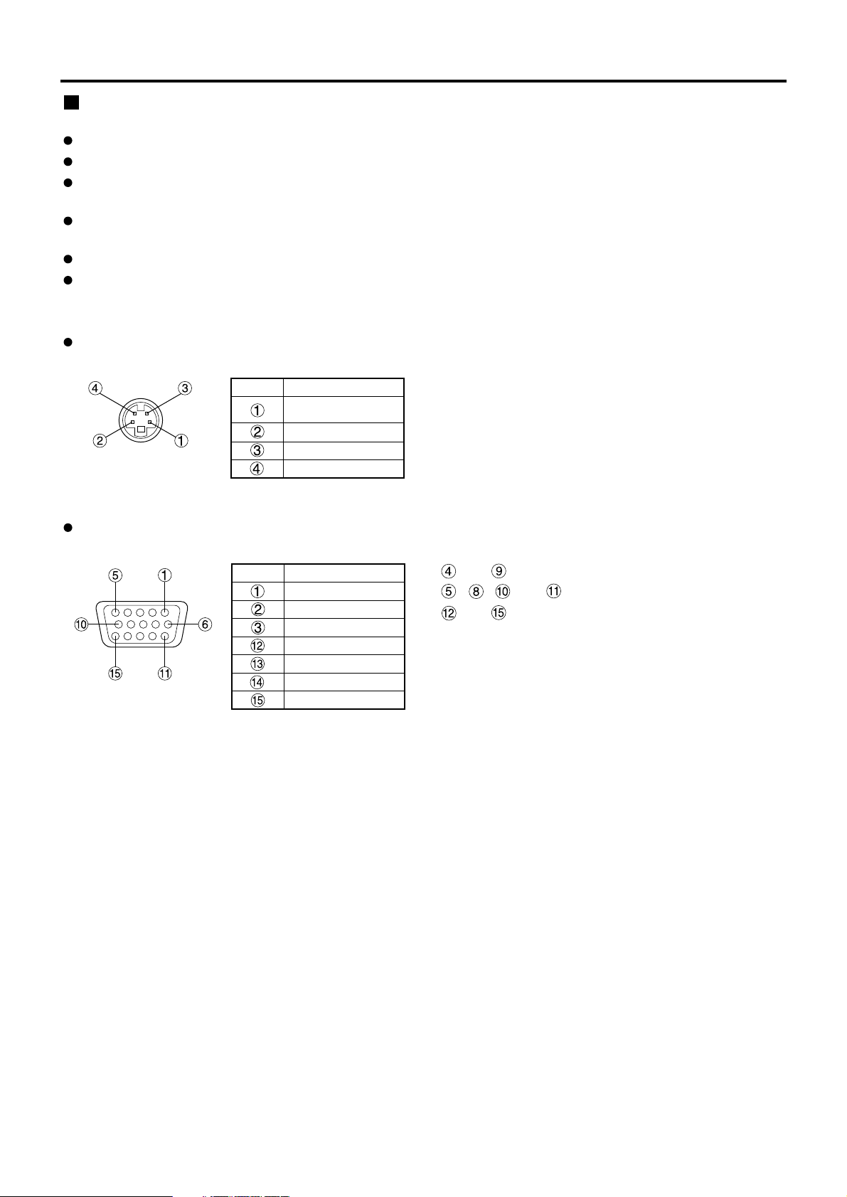
The pin-out and signal names of the S-VIDEO IN terminal are shown in the diagram below.
The pin-out and signal names of the RGB2 input terminal are shown in the diagram below.
Outside view
Pin No.
Ground (color signal)
Luminance signal
Color signal
Signal
Ground
(luminance signal)
Outside view
Signal
R/P
R
G/G · SYNC/Y
P
B
SDA
HD/SYNC
VD
SCL
Pin No.
Before starting connection
and are not assigned.
~ , and are GND terminals.
and are effective if the PC has the corresponding
functions.
Page 25
25
SERIAL
S-VIDEO
VIDEO
REMOTE 1
RGB 1 IN
IN
IN
IN
OUT
OUT
OUT
SYNC/HD VDB/PBG/Y
REMOTE 2
R/PR
RS-232C (G) / RS-422 (R)RS-232C (G) / RS-422 (R)
IN
RGB 2 IN
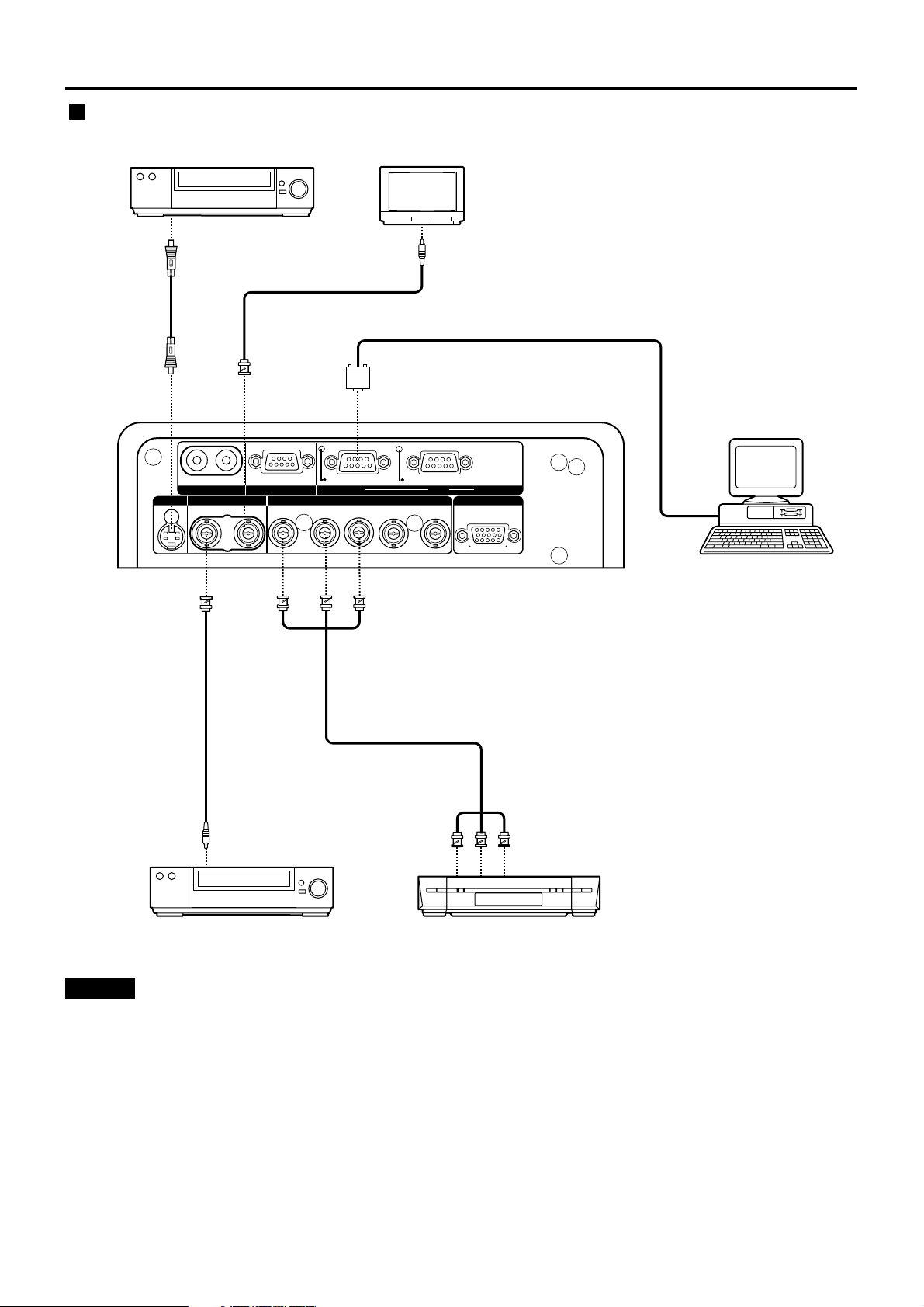
Video deck (TBC built-in)
High-vision video deck
Control PC
Color monitor
Red (connected to PR terminal)
Blue (connected to P
B terminal)
Green (connected to Y terminal)
Video deck (TBC built-in)
Example of connecting with VIDEO devices
• When connecting with a video deck, be sure to use the one with a built-in time base corrector (TBC) or
use a TBC between the projector and the video deck.
• If nonstandard burst signals are connected, the image may be distorted. If this is the case, connect a
TBC between the projector and the video deck.
Attention
Page 26
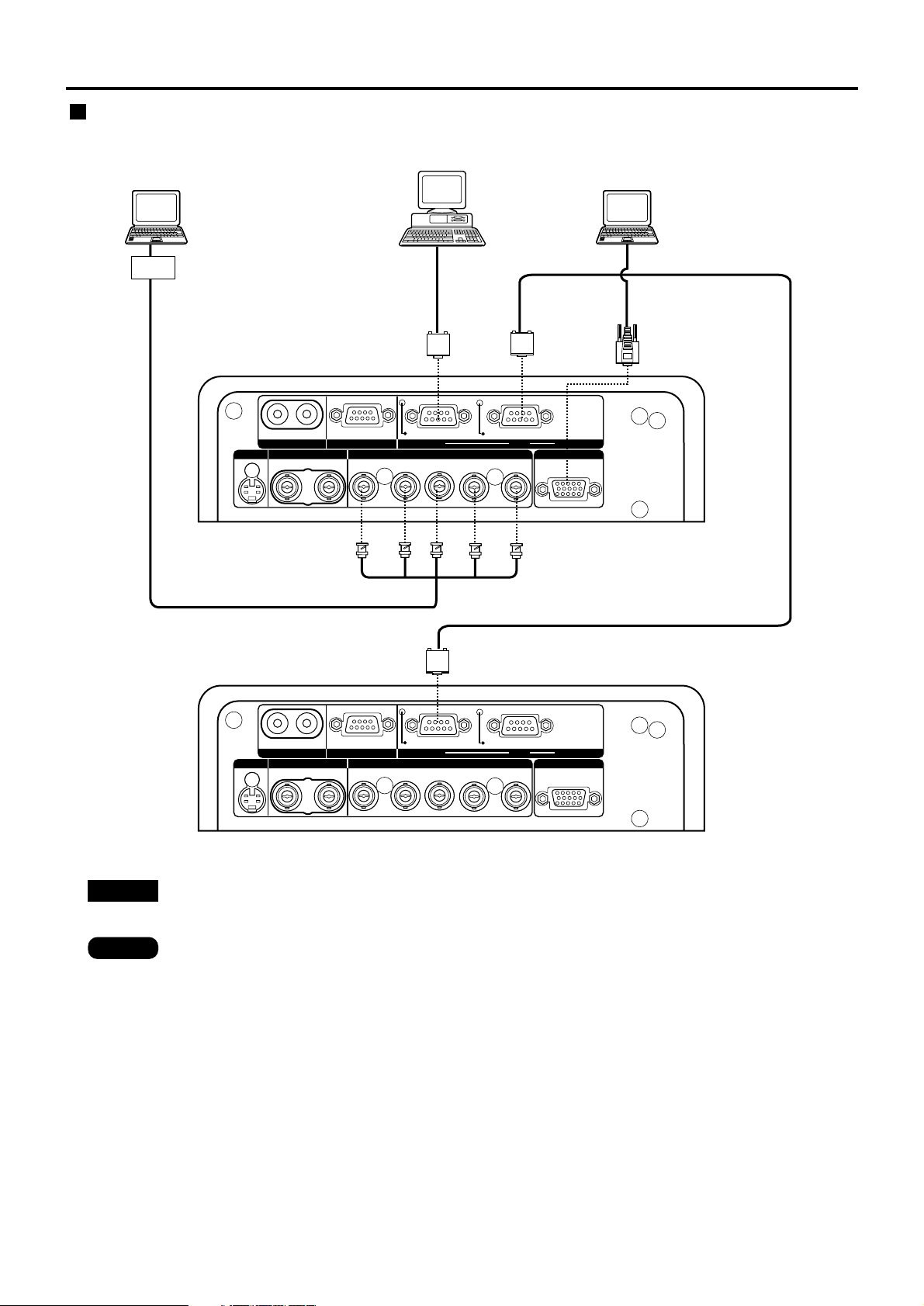
26
SERIAL
S-VIDEO
VIDEO
REMOTE 1
RGB 1 IN
IN
IN
IN
OUT
OUT
OUT
SYNC/HD VDB/PBG/Y
REMOTE 2
R/PR
RS-232C (G) / RS-422 (R)RS-232C (G) / RS-422 (R)
IN
SERIAL
S-VIDEO
VIDEO
REMOTE 1
RGB 1 IN
IN
IN
IN
OUT
OUT
OUT
SYNC/HD VDB/PBG/Y
REMOTE 2
R/PR
RS-232C (G) / RS-422 (R)RS-232C (G) / RS-422 (R)
IN
RGB 2 IN
RGB 2 IN
I/F
PC PC
Control PC
• When the main power of the main unit is turned off, also turn off the power of the PC.
Note
Attention
• For the specifications of the RGB signals that can be applied from the PC, see the data sheet on
page 106.
• If your PC has the resume feature (last memory), the computer may not function properly until the
resume capability is disabled.
Example of connecting with personal computers
Connection
Page 27
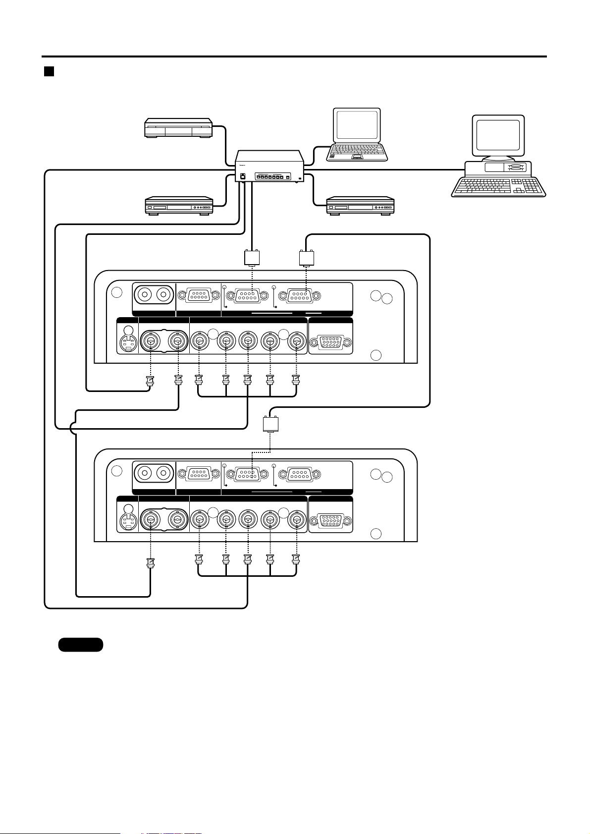
27
SERIAL
S-VIDEO
VIDEO
REMOTE 1
RGB 1 IN
IN
IN
IN
OUT
OUT
OUT
SYNC/HD VDB/PBG/Y
REMOTE 2
R/PR
RS-232C (G) / RS-422 (R)RS-232C (G) / RS-422 (R)
IN
SERIAL
S-VIDEO
VIDEO
REMOTE 1
RGB 1 IN
IN
IN
IN
OUT
OUT
OUT
SYNC/HD VDB/PBG/Y
REMOTE 2
R/PR
RS-232C (G) / RS-422 (R)RS-232C (G) / RS-422 (R)
IN
RGB 2 IN
RGB 2 IN
OUT
O
F
F
O
F
F
P
O
W
E
R
O
N
I
N
P
U
T
S
E
L
E
C
T
1
2
34
5
6
V
P
O
N
/
O
F
F
S
i
g
n
a
l
S
e
l
e
c
t
o
r
T
W
-
S
W
S
Digital broadcasting
tuner
DVD player
Signal selector
Video deck
(TBC built-in)
Notebook computer
Control PC
Note
• When multiple signals of the same type are switched and input to RGB1 IN (for example, when
switching multiple high-vision signals for usage), use a dedicated signal selector. When the signal
selector is connected to the projector with a RS-232C cable, signals can be used separately
according to the input terminal on the signal selector.
• Carefully read also the instruction manual for the signal selector.
Example of connecting with the signal selector
Page 28
28
Input signal
Serial digital signal
Serial digital signal
HD serial digital signal
VGA, SVGA, XGA,
SXGA
Module model No
.
ET-MD95RGB
ET-MD95VM2
ET-MD95SD1
ET-MD95SD2
ET-MD95SD3
ET-MD75DV
ET-MD75NT
Input signal level
Image signal input: impedance of 75 Ω
Synchronizing signal input
: impedance of 75 Ω /1 kΩ
R/PR/Cr:
0.7 V [p-p]: 1.0 V [p-p] for
BETACAM input.
G/Y: 0.7 V [p-p]:
1.0 V [p-p] for SYNC ON G/Y
signal input.
B/PB/Cb: 0.7 V [p-p]:1.0 V [p-p] for
BETACAM input.
0.6 V [p-p]-4.0 V [p-p] for
composite SYNC 75 Ω
For 1 kΩ: TTL level
Three value composite
SYNC not supported
For separate SYNC 75 Ω:
0.6 V [p-p] - 4.0 V [p-p]
For 1 kΩ: TTL level
Signals supporting analog RGB input modules
fH: 15 kHz-100 kHz,
fV: 24 Hz -120 Hz,
Dot clock frequency: 20 MHz -162 MHz
Signals supporting color-difference input
Types Supported: 480i, 576i, 480p, 576p,
720/60p, 1080/60i(1035/60i)
,
1080/50i,1080/30p,1080/25p,
1080/24p, 1080/24sF
Video/Y 1.0 V [p-p]
C: 0.286 V [p-p]
Cr / Cb: 0.7 V [p-p]
Impedance: 75 Ω
SMPTE259M compliant
SMPTE259M/294M compliant
SMPTE292M compliant
DVI1.0 compliant
Displayable resolution: VGA - SXGA
Dot clock frequency: 25 MHz -112 MHz
Format: BMP, JPEG, PNG
Number of pixels: 1 024 x 768 dots
Display colors: 65 536 colors
Separate software is necessary to display image
files. Please contact the dealer.
Video signal
Analog RGB signal
Image file
Installation of input module (optional)
Installing the input module
Types of the input modules (optional)
Prepare beforehand an input module (optional) compatible with the input signals of the system.
Page 29
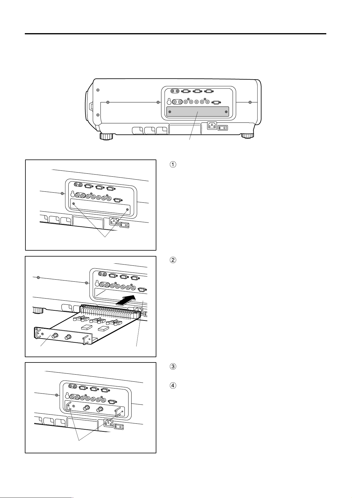
29
Procedure of installation
Disconnect the power before installing the input module.
Slot cover
Remove 2 screws.
Input module Slot
Tighten the two screws.
Remove the slot cover.
Insert the input module.
Fix the input module.
Register the input signal.
This projector needs to register the type of input
signal after the installation of the input module.
(For details on the registration of the input signals,
refer to pages 44–47.)
Page 30
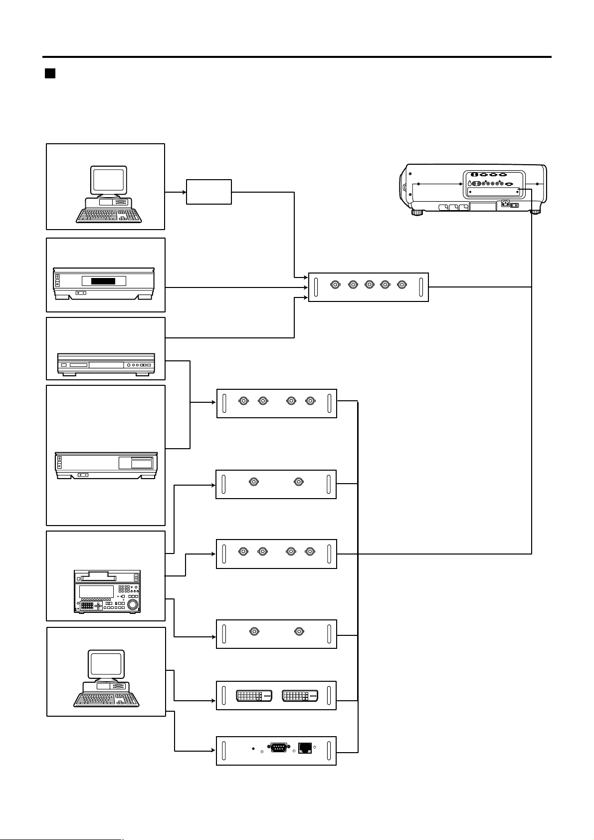
30
I/F
RGB signal
Component signal
Video signal input
module ET-MD95VM2
Serial digital input
module ET-MD95SD1
Component signal
SD signal
High-vision video deck
Video deck
(TBC built-in)
Business
digital VCR
PC
Serial digital input
module ET-MD95SD2
DVD player /
BS digital HD tuner
HD serial digital input
module ET-MD95SD3
DVI input module
ET-MD75DV
SD signal
SD signal
DVI
signal
PC
Network module
ET-MD75NT
LAN
Projector
RGB signal input module
ET-MD95RGB
Connecting signals to the input module
When installing the projector, it is necessary to connect signals to the input module in accordance with the
connecting equipment.
Refer to the following diagram to establish proper signal connection.
Installation of input module (optional)
Page 31

31
An interface (D-SUB BNC) is necessary to connect the projector with a PC using an analog RGB signal input
module.
1. Connecting analog RGB signals
PC
R/P
R
G/Y B/P
B
H/H·VV
D-SUB BNC
×5 (conversion connector)
RGB signal input module (optional)
ET-MD95RGB
RGB Module
ET-MD95RGB
H/ H.V
RGB V
• The module does not support the three value
synchronizing input to the H/H•V and V terminals.
• Do not supply synchronizing input signals to H/H•V and V
terminals when supplying SYNC ON GREEN signals.
Attention
(Please purchase commercially available interface.)
2. Connecting the component signals
PR/CrYPB/C
b
PR/CrYPB/C
b
High-vision video deck
R/P
R
G/Y B/P
B
H/H·VV
DVD player /
BS digital HD tuner
RGB signal input module (optional)
ET-MD95RGB
RGB Module
ET-MD95RGB
Connecting the signal to the analog RGB signal input module
Page 32

32
1. Connecting the video signals
Image signal
Luminance
signal
Color
signal
Monitor TV
Video signal input module (optional)
ET-MD95VM2
DVD player Video deck (TBC built-in)
LINE/Cr IN
C/Cb INLINE OUT
Y IN
S terminal BNC
×2 (conversion connector)
S terminal
Video Module
ET-MD95VM2
BS digital HD tuner
Image signal
• An optional slot selector (AUX) button toggles between the LINE and Y/C input.
(Example) Each time AUX button is pressed,
LINE input Y/C input
The above cycle is repeated.
• When connecting with a video deck, be sure to use the one with built in TBC (time base corrector) or use the
time base corrector between the projector and the video deck.
• If burst signals are connected to the nonstandard signals, the image may be distorted. If this is the case,
connect the time base corrector between the projector and the video deck.
Connecting the signal to the video signal input module
Installation of input module (optional)
Page 33

33
2. Connecting the component signals
Color-difference
signals Cb
DVD player
LINE/Cr IN
C/Cb INLINE OUT
Y IN
Video Module
ET-MD95VM2
Video signal input module (optional)
ET-MD95VM2
Color-difference
signals Cr
Luminance signals Y
Video deck (TBC built-in)
• For details on switching between the video signals connection and the component signals connection, refer
to the section for switching the signals of ET-MD95VM2 (optional) on page 81.
Page 34

34
• Insert the input module suitable for the input signal specifications.
• Use the SYSTEM SELECTOR button to toggle the systems of the input module that supports two types of
signal specifications. Upon toggling, the input signals are displayed on the screen and cleared automatically.
Connecting the signal to the serial digital signal input module
Installation of input module (optional)
Serial digital input module (optional)
ET-MD95SD1 (for 480i/576i)
480i Module
ET-MD95SD1
IN
SERIAL
SD signal
Business digital
video deck
OUT
SD signal output
(active through)
Page 35

35
1. For 480p dual link (4:2:2p) SMPTE294M-compliant, 720x483 active line 59.94 Hz
progressive scan 270 Mbps
• Insert the input module that meets the input signal specifications.
• Use the SYSTEM SELECTOR button to select the input module that meets desired one of the above four
types of signal specifications. While toggling through those four types, input signal and other information
are displayed and cleared on the screen automatically.
• Normally, use SYSTEM SELECTOR in “AUTO”.
• Automatic detection may malfunction if connection is made in any other way than listed above or if any
unstable signal is connected. If this happens, switch to a system that is compatible with the signal format
using the SYSTEM SELECTOR button.
• Use a 3C2W or superior cable for connection to transmit the image information without error.
(Example: 3C2W, 3CFB, 4CFB, 5C2W, 5CFB, 5CFTX, 7CFB etc.)
2. 1) For 480p single link (4:2:0p) SMPTE294M-compliant, 720x483 active line 59.94 Hz
progressive scan 360 Mbps
2. 2) For 480i (4:2:2): SMPTE259M-compliant, 59.94 Hz 525 Line 270 Mbps
3) For 576i (4:2:2): SMPTE259M-compliant, 50 Hz 625 Line 270 Mbps
(Continued on next page)
Serial digital input module (optional)
ET-MD95SD2 (for 480p/480i/576i)
MAIN IN
480p Module
ET-MD95SD2
MAIN OUT SUB IN SUB OUT
SERIAL
SD signal
MAIN
(Link-A)
SUB
(Link-B)
MAIN
(Link-A)
SUB
(Link-B)
Business-use
digital video deck
SD signal output
(active through)
Serial digital input module (optional)
ET-MD95SD2 (for 480p/480i/576i)
MAIN IN
480p Module
ET-MD95SD2
MAIN OUT SUB IN SUB OUT
SERIAL
Connect nothing to
SUB IN/OUT terminals.
SD signal
Business-use
digital video deck
SD signal output
(active through)
Page 36

36
• Insert the input module that meets the input signal specifications.
• Use the SYSTEM SELECTOR button to select the input module that meets desired one of the eight types
(14 formats) of signal specifications (SMPTE292M).
While toggling through those eight types, input signal and other information are displayed and cleared on the
screen automatically.
• Normally, use SYSTEM SELECTOR in “AUTO”.
• Automatic detection may malfunction if connection is made in any other way than listed above or if any
unstable signal is connected. If this happens, switch to a system that is compatible with the signal format
using the SYSTEM SELECTOR button.
• Use a 5CFB or superior cable for connection to transmit the image information without error.
(Example: 5CFB, 5CFTX, 7CFB etc.)
Installing the input module (optional)
Connecting the signal to the serial digital signal input module (continuing)
Serial digital input module (optional)
ET-MD95SD3 (for HD SDI)
1080i/720p Module
ET-MD95SD3
IN
HD SERIAL
HD SD signal
Business-use
digital video deck
OUT
HD SD signal output
(active through)
1080/60iAUTO 1035/60i 720/60p
1080/24sF
1080/25p 1080/30p 1080/50i
1080/24p
Page 37

37
DVI-D IN DVI-D OUT
DVI Module
ET-MD75DV
ET-MD75DV
DVI-D input module (optional)
DVI signal
PC with DVI output
Connecting signals to the DVI signal input module
External view
• Pin assignments and signal names of DVI-D input
terminal are listed in the table at right (terminal for
TMDS-equipped PC).
• The DVI-D signal input module supports only a single
link.
Pin No. Pin No.
Signal
TMDS data 2–
TMDS data 2+
TMDS data 2 / 4
shield
(T.M.D.S data 4–)
(T.M.D.S data 4+)
DDC clock
DDC data
T.M.D.S data 1–
T.M.D.S data 1+
T.M.D.S
data
1/3
shield
(T.M.D.S data 3–)
Signal
(T.M.D.S data 3+)
+5V
Ground
Hot plug detection
T.M.D.S data 0–
T.M.D.S data 0+
T.M.D.S
data
0/5
shield
(T.M.D.S data 5–)
(T.M.D.S data 5+)
T.M.D.S clock
shield
T.M.D.S
clock+
T.M.D.S
clock–
Page 38

38
How to install and remove the projection lens (optional)
How to install the projection lens
While pressing the lock button on the
projection lens cover, pull the cover
forward to remove it.
Pull and remove the dustproof sheet on
the back of the projection lens cover.
Align the mark (orange) on the
projection lens with the mark on the
projector ( ), and then insert the
lens and turn it clockwise until it clicks
into place.
Insert the tab on the projection lens
cover into the projector, and mount the
projection lens cover while pressing
the lock button.
How to remove the projection lens
While pressing the lock button on the
projection lens cover, pull the cover
forward to remove it.
While holding down the lock button,
turn the projection lens
counterclockwise, and then pull it off.
Lens cover’s lock button Lens cover’s lock button
Mark (orange)
Lens cover’s lock button
Lens cover’s tab
Projection lens lock button
Page 39

39
Powering up the projector
Connect the supplied power cable.
(120 V AC, 50 Hz/60 Hz)
Press the “I” marked side of the MAIN
POWER switch to turn on the power.
The power indicator lamp on the projector will flash
in red. After a short period, the indicator will
illuminate and the projector will enter standby
mode.
Press the “l” button. [on the main unit
or the remote control]
The power indicator lamp illuminates in green and
soon the image is projected on the screen.
Making adjustment and selection
Roughly adjust the focus of the lens.
(Refer to page 41.)
Press the LENS button on the main unit or the
remote control unit to display a focus adjustment
screen. Pressing buttons to adjust
the image into focus.
Select and set the projection scheme.
(Refer to page 72.)
Select the input signal by pressing the
input selector button to toggle through
RGB1, RGB2, VIDEO, S-VIDEO and
AUX. [on the main unit or the remote
control]
Adjust the tilt of the main unit in front
and rear or right and left.
(Refer to page 18.)
Press the LENS button two or three
times to adjust the lens shift. (Refer to
page 41.)
• If the projector is powered up at about 0˚C, a warmup period of approximately five minutes may be
necessary to start projection.
The temperature monitor (TEMP) lamp lights up
during the warm-up period.
When the warm-up is completed, the temperature
monitor (TEMP) lamp turns off and the image is
projected on the screen.
• If the surrounding temperature is very low and the
warm-up period exceeds five minutes, the control
determines it as an abnormal condition and turns off
the power automatically. If this happens, raise the
surrounding temperature to 0°C or higher and then
turn the main power “on” and turn the power “on” (|).
• The AUX button is disabled when an optional input
module is not connected.
Note
AUTO
SETUP
RGB 1
VIDEO
MENU
ENTER
LENS
S-VIDEO
SHUTTER
RGB 2
AUX
POWER
ON OFF
RGB1RGB
2
AUX
MENU
STD
LENS
OSD
1
4
7
2
5
8
3
6
9
0
NEXT
USER
LIGHT
ID ALL
ASPECT
ID SET
Projector
Computer
Numetric
BRIGHT
CONTRAST
ON SCREEN
SYSTEM
SEL
FUNC
1
D.ZOOM
ENTER
PAGE UP
PAGE DOWN
VIDEO
SHUT
S-
VIDEO
FREEZE
SHUTTER
AUTO
SETUP
LASER ON/OFF
Press the AUTO SETUP button if the
input signal is RGB signal. [on the
main unit or the remote control]
Fit the image size to the screen size.
(Refer to page 41.)
Press the LENS button twice and adjust the zoom
of the lens on the lens zoom adjustment menu.
Press the LENS button and adjust the
focus of the lens on the lens focus
adjustment menu.
Display the zoom adjustment menu
again and adjust the zoom of the lens
to fit the image size to the screen size.
(Refer to page 41.)
Projection
Page 40

40
Powering off the projector
Press the POWER OFF “” button.
Select “EXECUTE” with or button
and press the ENTER button.
(or press the POWER OFF “” button
again.)
The projection of the image stops, and the power
indicator lamp of the main unit lights up orange.
(The cooling fan keeps running.)
Wait until the power indicator lamp of
the main unit turns to red (i.e., until the
cooling fan stops). (Approx. 4 minutes)
While the cooling fan is still running, never turn off
the MAIN POWER switch, nor unplug the projector
from the outlet.
Press the “O” marked side of the MAIN
POWER switch to remove all power
from the projector.
• Turning on the power supply will not light up the light
source lamp if the lamp is in the process of cooling
down after turning off the power supply. To light up
the lamp, turn on the power supply again when the
lamp has been cooled sufficiently.
• The projector consumes approximately 12 watts of
power even in standby mode after the cooling fan
stops. (Power indicator lamp lit in red)
• If you re-power the projector after shutting off the
main power inadvertently, the projection lamp may
remain unlit. Please turn the power on again after a
while.
Note
AUTO
SETUP
RGB 1
VIDEO
MENU
ENTER
LENS
S-VIDEO
SHUTTER
RGB 2
AUX
POWER
ON OFF
RGB1RGB
2
AUX
MENU
STD
LENS
OSD
1
4
7
2
5
8
3
6
9
0
NEXT
USER
LIGHT
ID ALL
ASPECT
ID SET
Projector
Computer
Numetric
BRIGHT
CONTRAST
ON SCREEN
SYSTEM
SEL
FUNC
1
D.ZOOM
ENTER
PAGE UP
PAGE DOWN
VIDEO
SHUT
S-
VIDEO
FREEZE
SHUTTER
AUTO
SETUP
LASER ON/OFF
Projection
Page 41

41
If the focusing, zooming or positioning of the image projected on the screen is not successful, even though the
projector is properly positioned against the screen, you can adjust the focus, the zoom, or the vertical or horizontal
position of the image.
Do not move the lens beyond the bounds of the shift range as this may cause a change in the focus. This limitation
is to protect the parts of the projector.
Using the standard projection position as the reference, the optical axis shift function makes it possible to adjust
the projection position in the ranges shown in the figures below.
Press the LENS button on the remote
control or on the control panel of the
main unit.
Pressing the button changes the setup screen in
the order of “LENS FOCUS”, “LENS ZOOM” and
“LENS SHIFT”.
Choose an item and adjust it using
buttons.
How to adjust the lens
Caution
Be careful not to catch your fingers between the
lens and shroud when shifting the lens.
How to adjust the lens focus,
lens zoom and lens shift
(optical shift)
Adjustment range after lens position (optical shift)
• The lens zoom adjustment menu will be
displayed only when a lens with zoom
function is being used.
Note
LENS
FOCUS
LENS
ZOOM
LENS
SHIFT
PT-D7700U
0.3H 0.3H
0.50V0.50V
0.1V 0.1V
0.1V 0.1V
Projected
screen
height,V
Projected
screen width,H
Standard
projection position
PT-DW7000U
Projected
screen
height,V
Projected
screen width,H
Standard
projection position
0.70V
0.2V
0.70V
0.2V
0.2V 0.2V
0.3H 0.3H
Page 42

42
How to adjust the lens
If the image is out of focus in any portion of the screen, adjust the lens by turning the adjustment screws to obtain
evenness of focusing.
How to adjust the lens for addressing unevenness of focusing
Remove the lens cover and lens (Refer to
page 38).
Loosen the three fixing screws that secure
the lens bracket about two turns.
• Tool to be used : Allen hex socket driver or Allen
wrench (2.5-mm diagonal hexagon)
Install the lens removed in step .
Adjust the lens by turning the adjustment
screws , , and counterclockwise.
• Tool to be used : Allen hex socket driver or Allen
wrench (2.5-mm diagonal hexagon)
Vup
H
left
H
right
Vbottom
a
b
c
Fixing screwsLens bracket
V up is out of focus
V bottom is out of focus
The instructions within parentheses apply to ceiling mount installation.
(Turn counterclockwise)
Turn counterclockwise
()
H right is out of focus
()
H left is out of focus
()
Turn counterclockwise
()(Turn counterclockwise)
Turn counterclockwise
()(Turn counterclockwise)
Turn counterclockwise
()(Turn counterclockwise) (Turn counterclockwise)
Turn counterclockwise
()
(For example)
When the image is out of focus in the upper portion of the
screen (V up):
Turn the adjustment screws and little by little
counterclockwise while checking evenness of focusing in
the upper and lower portions.
Adjust the screws , , and after
installing the lens.
Note
• Be sure to tighten the fixing screws before
transportation.
Page 43

43
Automatic adjustment (AUTO SETUP)
Automatic adjustment function adjust the resolution, clock phase and image position automatically when dotsstructured analog RGB signals such as computer signal are supplied. (Automatic adjustment is not available if
signals or moving images other than analog RGB signals are supplied.)
It is recommended to supply images with a bright white frame at the outermost periphery containing characters etc.
that are clear in white and black contrast when the system is in automatic adjustment mode. Avoid supplying
images that involve halftones or gradation such as photographs and computer graphics.
Note
• A message “COMPLETE” appears if adjustment is ended normally.
• “CLOCK PHASE” may have been shifted even when the adjustment ended normally.
In this case, manually adjust the “CLOCK PHASE”.
• If an image with blurred edges or a dark image is supplied, a message “INCOMPLETE” appears,
indicating the automatic adjustment was unsuccessful.
In this case, manually adjust the items of “INPUT RESOLUTION”, “CLOCK PHASE” and “SHIFT”.
• For specific signals and long-sideways (or landscape) signals such as 16:9, adjustment should be
made according to “AUTO SETUP” in the option menu.
• Automatic adjustment may not be available depending on the machine type of the personal computer.
• Automatic adjustment may not available for synchronization signal of C-SYNC and G-SYNC.
• Image may be distorted for several seconds during automatic adjustment. This is not a malfunction.
• For every supplied signal, adjustment is required.
• Automatic adjustment can be cancelled by pressing the MENU button during the course of automatic
adjustment.
Page 44
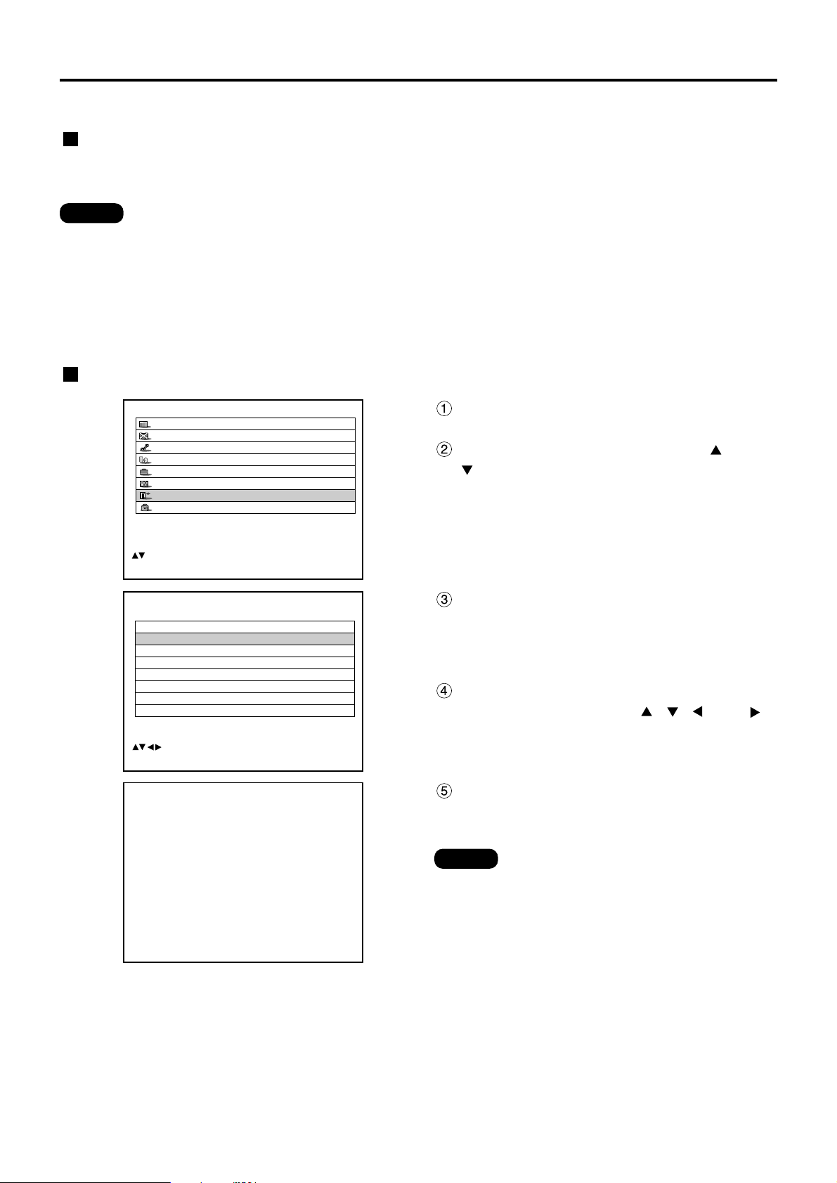
44
Registration of input signal data
• The data of 96 input signals can be registered.
• The signals supporting the installed input module are input and their data registered.
• The memories are numbered over 12 pages (A to L: 8 data items can be registered on each page),
and the data is registered in the unused memory with the lowest number. If all the memories are used,
the data of the old signals is overwritten in sequence.
• The names of the registered data are automatically determined by the input signals and memory
numbers.
The input signal data must be registered because it is not registered on shipment of the projector.
Note
Renaming the registered signals
Registration of new data
When a new signal is supplied, press the “MENU” button on the remote control or operating section of the main
unit. When its data has been registered, the MAIN MENU screen is displayed.
Press the “MENU” button.
The MAIN MENU screen will be displayed.
Select “SIGNAL LIST” with the and
buttons.
Note
MAIN MENU
PICTURE
POSITION
ADVANCED MENU
LANGUAGE
OPTION
TEST PATTERN
SIGNAL LIST
SECURITY
:MENU SELECT
ENTER:SUB MENU
REGISTERED SIGNAL LIST
A1:SVGA72-A1 RGB1 – – –
A2:SVGA72-A2 RGB1 – – –
A3:SVGA72-A3 RGB1 – – –
A4:SVGA72-A4 RGB1 – – –
A5:SVGA72-A5 RGB1 – – –
A6:SVGA72-A6 RGB1 – – –
A7:SVGA72-A7 RGB1 – – –
A8:SVGA72-A8 RGB1 – – –
:SELECT ENTER:DETAILS STD:DELETE
REGISTERED SIGNAL STATUS
NAME: SVGA72-A2
MEMORY NO: A2
S.S.NO: – – –
INPUT NO: RGB1
fH: 48.08kHz
fV: 72.17Hz
SYNC. STATE: H(POS)
V(POS)
ENTER:CHANGE NANE
Press the “ENTER” button.
The REGISTERED SIGNAL LIST screen will be
displayed. The memories extend over 12 pages (A
to L with 8 data items each, giving a total of 96
memories).
Select the signal whose details are to
be displayed with the
, ,
and
buttons.
Press the “ENTER” button.
The REGISTERED SIGNAL STATUS screen will
be displayed.
• The data items including the input signal
name, memory number, signal selector
input number, input terminal, frequency
and sync signal are automatically
identified and displayed.
• When the “MENU” button is pressed, the
REGISTERED SIGNAL LIST screen is
restored.
Page 45

45
Clearing the data of registered signals
Press the “MENU” button.
The MAIN MENU screen will be displayed.
Select “SIGNAL LIST” with the and
buttons.
Press the “ENTER” button.
The REGISTERED SIGNAL LIST screen will be
displayed. The memories extend over 12 pages (A
to L with 8 data items each, giving total of 96
memories).
Select the signal whose data is to be
cleared with the
, ,
and
buttons.
MAIN MENU
PICTURE
POSITION
ADVANCED MENU
LANGUAGE
OPTION
TEST PATTERN
SIGNAL LIST
SECURITY
:MENU SELECT
ENTER:SUB MENU
REGISTERED SIGNAL LIST
A1:SVGA72-A1 RGB1 – – –
A2:SVGA72-A2 RGB1 – – –
A3:SVGA72-A3 RGB1 – – –
A4:SVGA72-A4 RGB1 – – –
A5:SVGA72-A5 RGB1 – – –
A6:SVGA72-A6 RGB1 – – –
A7:SVGA72-A7 RGB1 – – –
A8:SVGA72-A8 RGB1 – – –
:SELECT ENTER:DETAILS STD:DELETE
ENTRY SIGNAL CLEAR
OK?
NAME: SVGA72-A2
MEMORY NO: A2
S.S.NO: – – –
INPUT NO: RGB1
fH: 48.08kHz
fV: 72.17Hz
SYNC. STATE: H(POS)
V(POS)
ENTER:EXECUTE MENU:ESC
RENAME
NAME: SVGA72-A2
MEMORY NO
:A2
S.S.NO: – –
INPUT NO:
RGB1
fH: 48.08kHz
fV: 72.17Hz
SYNC. STATE: H(POS)
V(POS)
:
NEXT FIGURE
:
FONT SELECT
ENTER:SET MENU:ESC
Press the “STD” button.
The ENTRY SIGNAL CLEAR screen will be
displayed.
If the data is not to be cleared, press the MENU
button to return to the SIGNAL LIST screen.
Press the “ENTER” button.
The data of the signal selected in step is
cleared.
Press the “ENTER” button.
The RENAME screen will be displayed.
Select each character with the and
buttons, and set the character or
number with the and buttons
(press the “STD” button to clear the
name which is automatically
displayed). After the signal has been
renamed, press the “ENTER” button.
After registration, the REGISTERED SIGNAL
STATUS screen is restored.
Note
• When the “MENU” button is pressed
instead of the “ENTER” button, the new
signal name will not be registered, and the
automatically displayed signal name will
be retained.
Page 46

46
Registration of input signal data
Sub memory
The projector is provided with a sub memory function to register plural pieces of image adjustment data even they
are determined to be the same signal by the frequency and form of the synchronization signal source.
Use this function when the user needs adjustment of picture quality such as aspect switching and white balance
using the same signal source.
Sub-memory contains all data that can be adjusted by signals such as screen aspect ratio and image adjustment
data (BRIGHT, CONTRAST etc.).
How to register into sub memory
A new signal cannot be registered into sub memory. A new signal must undergo signal registration.
SUB MEMORY LIST
1- 1:SXGA60-A1
1- 2:SXGA60-A2
1- 3: – – –
1- 4: – – –
1- 5: – – –
1- 6: – – –
1- 7: – – –
1- 8: – – –
:SELECT ENTER:CHANGE STD:DELETE
REGISTER SUB MEMORY?
NAME: SXGA60-A1
MEMORY NO: – –
S.S.NO: – – –
INPUT NO: RGB1
fH: 48.00kHz
fV: 60.00Hz
SYNC. STATE: H(POS)
V(POS)
ENTER:EXECUTE MENU:ESC
Press the “USER” button on normal
screen (menu is not displayed).
(A “Check sub-memory registration” screen will
appear if sub-memory has not been registered.)
The screen will show a list of the sub-memory
registered for the currently entered signal.
Select the SUB MEMORY number
stored with the , , and
buttons in the “Signal List”.
Press the “ENTER” button.
A “Change registered signals” screen will appear.
Press the “ENTER” button.
Procedure to switch to sub memory
Press the “USER” button on normal screen (menu is not displayed).
The screen will show a list of the sub-memory registered for the currently entered signal.
In the “Signal List”, select the sub-memory signal to be switched using the , ,
and buttons.
Press the “ENTER” button.
Signal will be switched to the one that was selected in Step .
How to erase sub memory
The currently selected SUB MEMORY is deleted by pressing the standard button (STD) at the “REGISTERED SIGNAL
LIST” or the “SUB MEMORY LIST”.
• To rename a registered signal, perform step on
page 45.
Note
Page 47

47
On-screen indications
Input switching / signal switching
This shows the registered signal name on the status screen for signal switching.
The designation can be set by the sub memory items.
The place in which address code
(A1, A2, ..., H7 and H8) signals are
registered
displays the sub
memory number.
Details of registered signal
Restrictions
The maximum sub memory items that can be registered for the projector are 96 including the basic signal.
Note
REGISTERED SIGNAL STATUS
NAME: SXGA60-A1
MEMORY NO
: ?? (1-2)
S.S.NO: – – –
INPUT NO
: RGB1
fH: 48.00kHz
fV: 60.00Hz
SYNC. STATE: H(POS)
V(POS)
ENTER:CHANGE NANE
NAME: RGB
MEMORY NO:
A1 (1-2)
S.S. NO: – – –
INPUT NO
: RGB1
MEMORY NO
: A1 (1-2)
Page 48

48
Using the FREEZE function
Pressing the “FREEZE” button of the remote control switches between a still image and a motion image.
If the projector is not used for a certain period of time during the meeting intermission, for example, a shutter mode
is available that allows the user to hide images temporarily.
Press the “SHUTTER” button of the remote control or the main unit.
The image is turned off.
Press the “SHUTTER” button again.
The image comes back.
A portion of the picture on the screen can be zoomed in with “– D.ZOOM +” buttons of the remote control. It is
useful for highlighting a specific object during the presentation.
Press the “– D.ZOOM +” button of the
remote control.
The image is zoomed in.
Change the magnification with the “–
D.ZOOM +” button.
The magnification can be adjusted from 1.0 to 3.0
times.
Use buttons to move the
magnified image.
To restore the original image, press the
“MENU” button.
• The digital zoomed state cannot be stored in memory.
• If the input signal format is changed while in digital zoom mode, the projector will exit digital zoom
function.
Attention
Still image
Motion image
A
B
C
D
E
ADJ
110
131
64
42
26
-
5
122
106
76
47
18
368 368
-
1
110
%
81
%
119
%
112
%
69
%
100
%
13%
21%
29%
32%
5%
E
18
122
106
76
47
D
C
B
A
A
B
C
D
E
ADJ
110
131
64
42
26
-
5
122
106
76
47
18
368 368
-
1
110
%
81
%
119
%
112
%
69
%
100
%
A
110
1
4
2
Using the SHUTTER function
Using the digital zoom (– D.ZOOM +) function
B
C
32%
D
13
6
4
Page 49

49
Structure of menu screens
Menus are extensively used for configuring, adjusting or reconfiguring the projector.
The menus structure is as follows:
MAIN MENU
PICTURE
POSITION
ADVANCED MENU
LANGUAGE
OPTION
TEST PATTERN
SIGNAL LIST
SECURITY
:MENU SELECT
ENTER:SUB MENU
PICTURE
PICTURE MODE DYNAMIC
COLOR 50
TINT 30
COLOR TEMP. DEFAULT
GAMMA 2.2
CONTRAST 32
BRIGHT 32
SHARPNESS 6
NOISE REDUCTION 2
DYNAMIC IRIS 1
:MENU SELECT
:CHANGE ENTER:REGISTER
POSITION
SHIFT
SIZE DEFAULT
CLOCK PHASE 0
KEYSTONE
:MENU SELECT
ENTER:SUB MENU
SIGNAL LIST
A1:SVGA72-A1 RGB1 – – –
A2:SVGA72-A2 RGB1 – – –
A3:SVGA72-A3 RGB1 – – –
A4:SVGA72-A4 RGB1 – – –
A5:SVGA72-A5 RGB1 – – –
A6:SVGA72-A6 RGB1 – – –
A7:SVGA72-A7 RGB1 – – –
A8:SVGA72-A8 RGB1 – – –
:SELECT ENTER:DETAILS STD:DELETE
OPTION
PROJECTOR ID 2
SETTING FRONT-F
LAMP SELECT DUAL
LAMP POWER HIGH
RS232C SETTING
OSD POSITION 2
SYSTEM INFORMATION
COLOR MATCHING OFF
VIDEO SETTING
AUTO SETUP
:MENU SELECT
:CHANGE
ADVANCED MENU
DIGITAL CINEMA REALITY
AUTO
FORMAT SMPTE
BLANKING
INPUT RESOLUTION
CLAMP POSITION
EDGE BLENDING OFF
SYNC.TERM 75
RASTER POSITION
:MENU SELECT
:CHANGE
OPTION
OUTPUT RESOLUTION SXGA+
AUTO SIGNAL ON
FAN CONTROL NORMAL
P IN P OFF
FUNC1 P IN P
PASSWORD
:MENU SELECT
:CHANGE
LANGUAGE
ENGLISH
DEUTSCH
FRANÇAIS
ESPAÑOL
ITALIANO
:SELECT ENTER:SET
LANGUAGE (page 68)
OPTION (pages 71-80)
SIGNAL LIST(pages 44 and 45)
SECURITY (page 86)
TEST PATTERN (page 85)
POSITION (pages 57-60)
ADVANCED MENU (pages 61-68)
MAIN MENU
PICTURE (pages 51-56)
On-screen menus
Page 50

50
On-screen menus
Basic operations on menu screen
Press the “MENU” button.
The MAIN MENU appears on the screen.
Select the desired item with the or
button.
Selected items are displayed in blue.
Press the “ENTER” button to establish
your selection.
The submenu for the selected option will now
open. (Example: PICTURE Menu)
Highlight the desired adjustment item
with the or button, then change
or adjust the parameter value with the
or buttons.
For the items such as “COLOR”, “TINT”, “CONTRAST”
and “BRIGHT”, an individual adjustment screen with an
individual bar graph as shown below is displayed by
pressing the ENTER button.
• If no button is operated for approx. 5 seconds while the
individual adjustment screen is displayed, the screen
will return to the previous page.
MAIN MENU
PICTURE
POSITION
ADVANCED MENU
LANGUAGE
OPTION
TEST PATTERN
SIGNAL LIST
SECURITY
:MENU SELECT
ENTER:SUB MENU
MAIN MENU
PICTURE
POSITION
ADVANCED MENU
LANGUAGE
OPTION
TEST PATTERN
SIGNAL LIST
SECURITY
:MENU SELECT
ENTER:SUB MENU
PICTURE
PICTURE MODE DYNAMIC
COLOR 50
TINT 30
COLOR TEMP. DEFAULT
GAMMA 2.2
CONTRAST 32
BRIGHT 32
SHARPNESS 6
NOISE REDUCTION 2
DYNAMIC IRIS 1
:MENU SELECT
:ADJUST
CONTRAST 32
Returning to the previous screen
• When the “MENU” is on the screen, pressing the
“MENU” button returns to the previous page.
• When the MAIN MENU is on the screen, pressing the
“MENU” button clears all menus from the screen.
Menu items shown in gray characters
•
Some menu items may not be valid for certain signal
formats applied to the projector.
The menu items that cannot be adjusted or used are shown
in gray characters, and they cannot be selected.
Menu items setting
The bottom prompt line differs on each menu
depending on the selected menu option:
• A prompt “ CHANGE” appears when
changing the setting.
• A prompt “ ADJUST” appears for a
separate bar graph.
• When and buttons are displayed above or
under the items in the “OPTION” screen, they
indicate that there are more adjustment (items).
Resetting to the factory default
STD (standard) button is used to reset all of the
projector adjustment values to the default levels which
were set at the time of shipment from the factory. It is
pressed after the respective adjustment mode screen
has been displayed.
• When the Menu screen is displayed:
A “STD” indicator appears on the upper right corner
of the menu.
PICTURE STD
PICTURE MODE DYNAMIC
COLOR 50
TINT 30
COLOR TEMP. DEFAULT
GAMMA 2.2
CONTRAST 32
BRIGHT 32
SHARPNESS 6
NOISE REDUCTION 2
DYNAMIC IRIS 1
:MENU SELECT
:ADJUST
Page 51

51
Adjusting the picture
Switching the picture mode
The user can switch to the desired picture mode suitable for the image source and the environment in which this
projector is used.
PICTURE
PICTURE MODE DYNAMIC
COLOR 50
TINT 30
COLOR TEMP. DEFAULT
GAMMA 2.2
CONTRAST 32
BRIGHT 32
SHARPNESS 6
NOISE REDUCTION 2
DYNAMIC IRIS 1
:MENU SELECT
:CHANGE ENTER:REGISTER
MAIN MENU
PICTURE
POSITION
ADVANCED MENU
LANGUAGE
OPTION
TEST PATTERN
SIGNAL LIST
SECURITY
:MENU SELECT
ENTER:SUB MENU
Press the “MENU” button.
The MAIN MENU screen will be displayed.
Select “PICTURE” with the
buttons.
Press the “ENTER” button.
The PICTURE screen will be displayed.
Select “PICTURE MODE” with the
buttons.
Switch “PICTURE MODE” with the
buttons.
DYNAMIC: The picture becomes suitable for the
use in well-lighted areas.
GRAPHIC: The picture becomes suitable for input
from to the personal computer.
USER: The COLOR, TINT, COLOR TEMP. and
GAMMA settings can be adjusted.
STANDARD: The picture becomes suitable for
moving images in general.
CINEMA: The picture becomes suitable for movie
sources.
NATURAL: The picture complies with sRGB.
• Factory defaults are “GRAPHIC” for RGB system and
“STANDARD” for moving images.
• When the “ENTER” button is pressed while
"PICTURE MODE" has been selected, the picture
mode which has been selected can be saved and
used as the presetting when new signals are input.
COLOR, TINT, COLOR TEMP. and GAMMA settings
are saved.
PICTURE MODE
GRAPHIC
DYNAMIC
USER
STANDARD
CINEMA
NATURAL
Page 52

52
Adjusting the picture
The desired picture can be obtained by following the procedure below.
Adjusting Contrast / Bright / Color / Tint
Adjustment procedure – to adjust picture (color intensity)
PICTURE
PICTURE MODE DYNAMIC
COLOR 50
TINT 30
COLOR TEMP. DEFAULT
GAMMA 2.2
CONTRAST 32
BRIGHT 32
SHARPNESS 6
NOISE REDUCTION 2
DYNAMIC IRIS 1
:MENU SELECT
:ADJUST
Press the “MENU” button.
The MAIN MENU screen will be displayed.
Select “PICTURE” with the
buttons.
MAIN MENU
PICTURE
POSITION
ADVANCED MENU
LANGUAGE
OPTION
TEST PATTERN
SIGNAL LIST
SECURITY
:MENU SELECT
ENTER:SUB MENU
Press the “ENTER” button.
The PICTURE screen will be displayed.
Select “CONTRAST” with the
buttons.
Press the “ENTER” button.
The CONTRAST individual adjustment screen will
be displayed.
Adjust the level with the buttons.
Thu function of the button changes according to
the item as shown in the following table:
Repeat Steps , and to adjust
the “BRIGHT”, “COLOR” or “TINT”.
The individual adjustment screen can be displayed
for “CONTRAST” and BRIGHT” by the remote
control. Refer to the following table:
To register the picture mode settings
which have been adjusted and use them
as the presettings, follow the procedure
on the next page from step .
Item Adjustment
Adjustment range
Remarks
CONTRAST
Raises the picture brightness and the picture becomes clearer.
Lowers the picture brightness and weakens the picture.
Maximum value 63
Minimum value 0
Use the CONTRAST button
on the remote
control.
Increases the brightness of the dark (black) parts of the screen.
Reduces the brightness of the dark (black) parts of the screen.
Deepens colors.
Weakens colors.
Adjusts skin tone toward reddish-purple.
Adjusts skin tone toward greenish color.
BRIGHT
COLOR
TINT
Maximum value 63
Minimum value 0
Maximum value 100
Minimum value 0
Maximum value 60
Minimum value 0
Use the BRIGHT button
on the remote control.
• If no button is operated for approx. 5 seconds while the individual adjustment screen is displayed, the
screen will return to the “PICTURE” screen.
Note
Press button
Press button
Operation
Press button
Press button
Press button
Press button
Press button
Press button
CONTRAST 32
Page 53

53
PICTURE
PICTURE MODE DYNAMIC
COLOR 50
TINT 30
COLOR TEMP. DEFAULT
GAMMA 2.2
CONTRAST 32
BRIGHT 32
SHARPNESS 6
NOISE REDUCTION 2
DYNAMIC IRIS 1
MAIN MENU
PICTURE
POSITION
ADVANCED MENU
LANGUAGE
OPTION
TEST PATTERN
SIGNAL LIST
SECURITY
:MENU SELECT
ENTER:SUB MENU
SAVE AS DEFAULT SETTING FOR DYNAMIC?
OK ESC
Registering the picture mode settings as presettings
The screen settings which have been adjusted by following the adjustment procedure (on the previous page) can
be registered.
Press the “MENU” button.
The MAIN MENU screen will be displayed.
Select “PICTURE” with the
buttons.
Press the “ENTER” button.
Select “OK” with the buttons.
Press the “ENTER” button.
Press the “ENTER” button.
The PICTURE screen will be displayed.
• If the registered picture mode is selected after registering the picture mode settings as presettings, the
new signals will be displayed with the registered adjustments.
Note
Page 54

54
Adjusting the picture
DYNAMIC IRIS
AUTO IRIS 2
MANUAL IRIS OFF
DYNAMIC GAMMA 1
:MENU SELECT
:CHANGE
2
3
1DYNAMIC IRIS
USER
OFF
DYNAMIC IRIS setting
Pictures with the optimum contrast will be displayed by automatically providing aperture compensation and signal
compensation to suit the pictures concerned.
Press the buttons on the “PICTURE”
screen to select “DYNAMIC IRIS”.
Select the "DYNAMIC IRIS" setting with
the buttons.
To further adjust the selected
compensation amount, select “USER”
in step .
Press the “ENTER” button.
The DYNAMIC IRIS screen will be displayed.
Select “AUTO IRIS”, “MANUAL IRIS” or
“DYNAMIC GAMMA” with the
buttons.
Adjust the compensation amount with
the buttons.
• The contrast is set to the maximum level when “DYNAMIC IRIS” is set to “3.”
Note
Aperture compensation and signal compensation
amounts
1: Low, 2: (Intermediate), 3: High
USER: (See below), OFF: No compensation
AUTO IRIS (Automatic aperture adjustment)
1: Low, 2: (Intermediate), 3: High,
OFF: No automatic compensation
MANUAL IRIS (Fixed aperture adjustment)
OFF: No fixed iris, 1: Low,
2-62: (Intermediate), 63: High
DYNAMIC GAMMA (signal compensation amount adjustment)
1: Low, 2: (Intermediate), 3: High,
OFF: No automatic compensation
Page 55

55
PICTURE
PICTURE MODE DYNAMIC
COLOR 50
TINT 30
COLOR TEMP. DEFAULT
GAMMA 2.2
CONTRAST 32
BRIGHT 32
SHARPNESS 6
NOISE REDUCTION 2
DYNAMIC IRIS 1
:MENU SELECT
:CHANGE
Press the “MENU” button.
The MAIN MENU screen will be displayed
Select “PICTURE” with the
buttons.
MAIN MENU
PICTURE
POSITION
ADVANCED MENU
LANGUAGE
OPTION
TEST PATTERN
SIGNAL LIST
SECURITY
Press the “ENTER” button.
The PICTURE screen will be displayed.
Select “COLOR TEMP.” with the
buttons.
Select the desired setting from below
with the buttons.
“LOW”, “MIDDLE”, “HIGH”, “DEFAULT”, “USER1”
and “USER2”
WHITE BALANCE
WHITE BALANCE HIGH
WHITE BALANCE LOW
<To further adjust toward the desired white balance>
Select “USER1” or “USER2” in Step .
Press the “ENTER” button.
Select “WHITE BALANCE HIGH” or
“WHITE BALANCE LOW” with the
buttons.
• All colors will not be displayed properly unless adequate adjustment is made.
If the adjustment is not successful, press “STD” (standard) button when the individual adjustment
screen is displayed to restore the factory default setting only for the displayed item.
• The color temperature cannot be adjusted for the internal test pattern (refer to page 85). Be sure to
project the input signal when adjusting the color temperature.
• When any setting other than “OFF” has been selected for color matching, the COLOR TEMP. setting is
fixed at “USER1”
• “DEFAULT” cannot be selected when the picture mode has been set to “USER”
Note
Press “ENTER” button.
The WHITE BALANCE HIGH (LOW) screen will be
displayed.
Select “R”, “G” or “B” with the
buttons.
Adjust the level with the buttons.
R (Red)
Deepens red.
Weakens red.
Deepens green.
Weakens green.
Deepens blue.
Weakens blue.
G (Green)
B (Blue)
Maximum value 255
Minimum value 0
WHITE BALANCE HIGH
R 255
G 255
B 255
Press button
Press button
Item Adjustment RemarksOperation
Adjusting the color temperature
Adjustment procedure (to be performed while projecting the signals to be adjusted)
Press button
Press button
Press button
Press button
Page 56

56
Adjusting the picture
Press the “MENU” button.
The MAIN MENU screen will be displayed.
Select “PICTURE” with the
buttons.
Press the “ENTER” button.
The PICTURE screen will be displayed.
Select desired one of the items in the
following table with the buttons.
Switch the setting with the
buttons.
Refer to the following table for the items and the
details.
Sharpness / Gamma / Noise reduction
Procedure of adjustment
PICTURE
PICTURE MODE DYNAMIC
COLOR 50
TINT 30
COLOR TEMP. DEFAULT
GAMMA 2.2
CONTRAST 32
BRIGHT 32
SHARPNESS 6
NOISE REDUCTION 2
DYNAMIC IRIS 1
:MENU SELECT
:ADJUST
MAIN MENU
PICTURE
POSITION
ADVANCED MENU
LANGUAGE
OPTION
TEST PATTERN
SIGNAL LIST
SECURITY
Adjustment items Adjustment
Sharpness
0 to 7 for the RGB system and the HD system
(factory setting is 2)
0 to 15 for the SD system (factory setting is 6)
5 settings: DEFAULT, USER1, USER2, 2.2 and
2.5
(factory setting: DEFAULT)
Gamma selection
Sharpens the outline of the image.
Switches the gamma modes
Operation
Four types: OFF (no correction), 1 (low),
2 (middle), 3 (high) (factory default: 2)
Noise reduction
Switches the noise reduction effect
mode.
Note
• Noise reduction cannot be adjusted with analog RGB input, DVI input or network input.
• Separate software is required to select “USER1” and “USER2” as the gamma setting. Consult your
dealer.
To display pictures complying with the sRGB standard
sRGB is the international color reproduction standard (IEC61966-2-1) established by IEC (International
Electrotechnical Commission).
To reproduce colors more faithfully in compliance with the sRGB standard, perform the following setting
procedure.
1. Set color matching adjustment to “OFF”.
2. Press the buttons on the “PICTURE” menu and select the “PICTURE MODE”.
Set to “NATURAL” with the buttons.
3. Select the “COLOR” with the buttons.
Press the STD (standard) button on the remote control to restore the factory default.
Follow the same procedure to restore the factory default for “TINT”, “COLOR
TEMP.” and “GAMMA”.
• sRGB is only enable when RGB signals are being input.
Note
Page 57

57
Adjusting the position
Desired position can be achieved by following the procedure below.
Shift adjustment
This function allows the user to adjust the picture position vertically or horizontally if the position of the image
projected on the screen is displaced when the projector is properly positioned against the screen.
Procedure of adjustment
POSITION
SHIFT
SIZE DEFAULT
CLOCK PHASE 0
KEYSTONE
:MENU SELECT
ENTER:SUB MENU
Press the “MENU” button.
The MAIN MENU screen will be displayed
Select the “POSITION” with the
buttons.
MAIN MENU
PICTURE
POSITION
ADVANCED MENU
LANGUAGE
OPTION
TEST PATTERN
SIGNAL LIST
SECURITY
:MENU SELECT
ENTER:SUB MENU
Press the “ENTER” button.
The POSITION screen will be displayed.
Select “SHIFT” with the buttons.
SHIFT
V: 0
H: 0
:ADJUST
Press the “ENTER” button.
The SHIFT screen will be displayed.
Adjust the position with the
buttons.
Press the “MENU” button three times.
The on-screen indications disappear and the
normal screen appears again.
Pressing button will
move the image to the
right.
Pressing button will
move the image to
the left.
Pressing button will
move the image upward.
Pressing button will
move the image
downward.
<For vertical (up and down) adjustment>
<For horizontal (right and left) adjustment>
Page 58

58
Adjusting the position
POSITION
SHIFT
SIZE DEFAULT
CLOCK PHASE 0
KEYSTONE
:MENU SELECT
:CHANGE ENTER:SUB MENU
Press the “MENU” button.
The MAIN MENU screen will be displayed.
Select the “POSITION” with the
buttons.
MAIN MENU
PICTURE
POSITION
ADVANCED MENU
LANGUAGE
OPTION
TEST PATTERN
SIGNAL LIST
SECURITY
:MENU SELECT
ENTER:SUB MENU
ZOOM
INTERLOCKED: OFF
V: 100 %
H: 100 %
HV: 100 %
:MENU SELECT
:CHANGE
Press the “ENTER” button.
The SIZE adjustment screen will be displayed.
Select the desired item with the
buttons.
Adjust with the buttons.
Size adjustment
Procedure of adjustment
Press the “ENTER” button.
The POSITION screen will be displayed.
Select “SIZE” with the buttons.
Using the buttons, select the size
mode.
For details on the size mode, refer to the next
page.
• If “THROUGH” is selected in the size mode, the individual adjustment screen is not displayed.
Note
Page 59

59
Some size modes are not available for certain types of input signals.
• For RGB1 and RGB2 input signals: VID AUTO, S1 AUTO or VID AUTO (PRIORITY) cannot be selected.
• For VIDEO input signals: DEFAULT, S1 AUTO or VID AUTO (PRIORITY) cannot be selected.
• For an NTSC signal with VIDEO or S-VIDEO input: DEFAULT cannot be selected.
Note
Size modes
• DEFAULT: Pictures are displayed without changing the aspect ratio of the input signals.
• THROUGH: Pictures are displayed without changing the resolution of the input signals.
• ZOOM: Pictures can be displayed in various magnifications. The user can magnify the pictures with the
magnification ranging from 50% to 999%, and the fiducial point is set on the top left of the screen.
• 16:9 (D7700U only): Pictures are displayed in the aspect ratio of 16:9.
• 4:3 (DW7000U only): Pictures are displayed in the aspect ratio of 4:3.
• S4:3 (D7700U only): Pictures are scaled down to 75% of the original size without changing the aspect ratio of the
input signals. This mode is used when projecting the 4:3 pictures on the 16:9 screen.
• H FIT (DW7000U only): Pictures are displayed using all the panel pixels in the horizontal direction.
Signals with an aspect ratio where the pictures are taller than with a ratio of 16:9 will be
displayed with their bottom areas cut off.
• HV FIT: Pictures are displayed on the whole panel pixels.
If the aspect ratio of the input signals is different from that of the panel, the pictures are displayed by
converting it into the panels aspect ratio (4:3 for PT-D7700U and 16:9 for PT-DW7000U).
• VID AUTO: The projector identifies the video ID (VID) embedded in the picture signals and displays the picture by
automatically switching the screen sizes between 4:3 and 16:9.
This function is effective for the video and S-video input.
• S1 AUTO: The projector identifies the S1 signal and displays the picture by automatically switching the screen
sizes between 4:3 and 16:9.
This function is effective for the S-video input.
• VID AUTO (PRIORITY): The projector identifies the abovementioned VID or S1 signals and displays the picture
by automatically choosing the screen sizes of 4:3 or 16:9 according to the VID if it is
detected or S1 signals if a VID is not detected.
This function is effective for the S-video input.
POSITION
SHIFT
SIZE DEFAULT
CLOCK PHASE 0
KEYSTONE
Press the “MENU” button.
The MAIN MENU screen will be displayed
Select the “POSITION” with the
buttons.
MAIN MENU
PICTURE
POSITION
ADVANCED MENU
LANGUAGE
OPTION
Press the “ENTER” button.
The POSITION screen will be displayed
Select “CLOCK PHASE” with the
buttons.
Adjust the clock phase with the
buttons.
The value changes from 0 to 31.
Clock phase adjustment
Clock phase adjustment achieves the best image when the screen flickers or halo is observed around the contour.
Procedure of adjustment
• No optimal value may be obtained if the output of the PC to which the signal input is applied is unstable.
• No optimal value may be obtained if the total number of dots is not correct.
• The clock phase can be adjusted only when RGB signal input is applied with RGB1, RGB2 IN, and the
analog input module (optional: ET-MD95RGB).
Note
Page 60

60
POSITION
SHIFT
SIZE DEFAULT
CLOCK PHASE 0
KEYSTONE
:MENU SELECT
ENTER:SUB MENU
MAIN MENU
PICTURE
POSITION
ADVANCED MENU
LANGUAGE
OPTION
TEST PATTERN
SIGNAL LIST
SECURITY
:MENU SELECT
ENTER:SUB MENU
KEYSTONE
KEYSTONE 63
LINEARITY 63
:ADJUST
Keystone distortion correction
Keystone distortion can be corrected only along either horizontal bound of the picture.
Procedure of adjustment
Note
Press the “MENU” button.
The MAIN MENU screen will be displayed.
Select the “POSITION” with the
buttons.
Press the “ENTER” button.
The POSITION screen will be displayed.
Select “KEYSTONE” with the
buttons.
Press the “ENTER” button.
The KEYSTONE screen will be displayed.
Adjust the “KEYSTONE” horizontally
with the buttons.
The value changes from 0 to 127.
Adjust the vertical “LINEARITY” with
the buttons.
The value changes from 0 to 127.
• Adjust the “LINEARITY” after adjusting the “KEYSTONE”.
The variable range of the “LINEARITY” changes in response to the adjusted value of the
“KEYSTONE”.
• Pressing STD (standard) button of the remote control will restore the factory default (“KEYSTONE”: 63,
“LINEARITY”: 63).
• The adjusted value is reflected in other input signals.
• Keystone distortion can be corrected to ±40° of the angle of tilt for the projector against the screen.
(The range for the angle of elevation is within ±19° when using a lens with a fixed focal point, and it is
within ±34° when using an LE1 lens.)
Adjusting the position
Page 61

61
How to use ADVANCED MENU
ADVANCED MENU
DIGITAL CINEMA REALITY
AUTO
FORMAT SMPTE
BLANKING
INPUT RESOLUTION
CLAMP POSITION
EDGE BLENDING OFF
SYNC.TERM 75
RASTER POSITION
:MENU SELECT
:CHANGE
MAIN MENU
PICTURE
POSITION
ADVANCED MENU
LANGUAGE
OPTION
TEST PATTERN
Press the “MENU” button.
The MAIN MENU screen will be displayed.
Select “ADVANCED MENU” with the
buttons.
Press “ENTER” button.
The ADVANCED MENU screen will be displayed.
Select “FORMAT” with the
buttons.
Switch the signal format with the
buttons.
• This toggles between SMPTE and BETACAM.
<Signal level>
Format
SMPTE
BETACAM
Y
700 mV
714 mV
Synchronous part
300 mV
286 mV
Cb , Cr
±350 mV
±504 mV
• This function is available only when input signals are supplied through the analog RGB input module
(ET-MD95RGB). RGB1, RGB2 inputs do not support BETACAM signals.
• This function can be switched only when receiving the picture of 480i in the YCbCr mode.
It cannot be switched when receiving the picture of signals other than RGB-REALITY mode, RGB
mode and 480i.
• SMPTE is the factory default.
Note
• In DIGITAL CINEMA REALITY mode, the image quality will be deteriorated if 30p FIXED or 25p FIXED
is selected when the signal is not a 2:2 pulldown signal.
Note
ADVANCED MENU
DIGITAL CINEMA REALITY
AUTO
FORMAT SMPTE
BLANKING
INPUT RESOLUTION
CLAMP POSITION
EDGE BLENDING OFF
SYNC.TERM 75
RASTER POSITION
MAIN MENU
PICTURE
POSITION
ADVANCED MENU
LANGUAGE
OPTION
DIGITAL CINEMA REALITY
Increase the vertical resolution when the PAL (or SECAM) 576i signal input or the NTSC 480i signal input is applied.
Procedure of adjustment
FORMAT (To input BETACAM with YCbCr 480i)
When receiving a picture of 480i with analog component signal YCbCr input, the input level of Cb and Cr can be switched.
Procedure of adjustment
Press the “MENU” button.
The MAIN MENU screen will be displayed.
Select “ADVANCED MENU” with the
buttons.
Press “ENTER” button.
The ADVANCED MENU screen will be displayed.
Select “DIGITAL CINEMA REALITY”
with the buttons.
OFF: Unforced cinema processing
AUTO: Performs automatic detection and cinema
processing. (factory default)
30p FIXED: Forced cinema processing (2:2
pulldown) is performed when a 480i
signal is input.
25p FIXED: Forced cinema processing (2:2
pulldown) is performed when a 576i
signal is input.
Page 62

62
How to use ADVANCED MENU
ADVANCED MENU
DIGITAL CINEMA REALITY
AUTO
FORMAT SMPTE
BLANKING
INPUT RESOLUTION
CLAMP POSITION
EDGE BLENDING OFF
SYNC.TERM 75
RASTER POSITION
:MENU SELECT
ENTER:SUB MENU
Press the “MENU” button.
The MAIN MENU screen will be displayed.
Select the “ADVANCED MENU” with
the buttons.
MAIN MENU
PICTURE
POSITION
ADVANCED MENU
LANGUAGE
OPTION
TEST PATTERN
SIGNAL LIST
SECURITY
:MENU SELECT
ENTER:SUB MENU
Press the “ENTER” button.
The ADVANCED MENU screen will be displayed.
Select “BLANKING” with the
buttons.
BLANKING
UPPER 0
LOWER 0
LEFT 0
RIGHT 0
:MENU SELECT
:ADJUST
Press the “ENTER” button.
The BLANKING adjustment screen will be
displayed.
Select the desired item for adjustment
with the buttons.
Adjust blanking with the buttons.
The value changes from 0 to 511.
Press button to move
the blanking zone upward;
button to downward.
Press button to move
the blanking zone upward;
button to downward.
Press button to move
the blanking zone to the
right; button to the left.
Press button to move
the blanking zone to the
right; button to the left.
<When correcting the left hand blanking of the
screen (left) >
<When correcting the upper blanking of the
screen (top) >
<When correcting the lower blanking of the
screen (bottom) >
<When correcting the right hand blanking of the
screen (right) >
Blanking adjustment
Blanking adjustment fine-tunes the images projected by the video deck or other devices when the noise appears on
the edges of the screen or if a part of the image lies slightly offscreen.
Procedure of adjustment
Page 63

63
ADVANCED MENU
DIGITAL CINEMA REALITY
AUTO
FORMAT SMPTE
BLANKING
INPUT RESOLUTION
CLAMP POSITION
EDGE BLENDING OFF
SYNC.TERM 75
RASTER POSITION
:MENU SELECT
ENTER:SUB MENU
MAIN MENU
PICTURE
POSITION
ADVANCED MENU
LANGUAGE
OPTION
TEST PATTERN
SIGNAL LIST
SECURITY
:MENU SELECT
ENTER:SUB MENU
INPUT RESOLUTION
TOTAL DOTS 1056
DISPLAY DOTS 832
TOTAL LINES 666
DISPLAY LINES 624
:MENU SELECT
:ADJUST
Press the “ENTER” button.
The INPUT RESOLUTION screen will be
displayed.
Select one of the following items with
the buttons and adjust it with the
buttons.
“TOTAL DOTS”, “DISPLAY DOTS”, “TOTAL
LINES” and “DISPLAY LINES”
Each item automatically displays a value in response
to the type of the input signal. If vertical stripes
appear on the screen or the image is partly missing,
increase or decrease the displayed value while
observing the screen to achieve the optimal value.
Adjusting the input resolution
Input resolution adjustment achieves the best image when the screen flickers or halo is observed around the
contour.
Procedure of adjustment
Press the “MENU” button.
The MAIN MENU screen will be displayed.
Select the “ADVANCED MENU” with
the buttons.
Press the “ENTER” button.
The ADVANCED MENU screen will be displayed.
Select “INPUT RESOLUTION” with the
buttons.
• The abovementioned vertical stripes will not appear on the screen when all signals are input.
• The picture may be distorted during the adjusting operation, but this is not a fault.
• The input resolution can be adjusted only when RGB signal input is applied with RGB1, RGB2 IN, and
the analog RGB input module (optional: ET-MD95RGB).
Note
Page 64

64
How to use ADVANCED MENU
ADVANCED MENU
DIGITAL CINEMA REALITY
AUTO
FORMAT SMPTE
BLANKING
INPUT RESOLUTION
CLAMP POSITION
EDGE BLENDING OFF
SYNC.TERM 75
RASTER POSITION
:MENU SELECT
ENTER:SUB MENU
MAIN MENU
PICTURE
POSITION
ADVANCED MENU
LANGUAGE
OPTION
TEST PATTERN
SIGNAL LIST
SECURITY
:MENU SELECT
ENTER:SUB MENU
CLAMP POSITION
POSITION 1
:MENU SELECT
:ADJUST
The optimal value for the clamp position adjustment
• If dark areas are crushed: The optimal value is the point where the dark area is best improved.
• If the dark areas are displayed in green: The optimal value is the point where the green area becomes dark
and clear.
Adjusting the clamp position
Use the clamp position adjustment to achieve the optimal value when dark areas of the image are crushed or
displayed in green.
Procedure of adjustment
Press the “MENU” button.
The MAIN MENU screen will be displayed.
Select “ADVANCED MENU” with the
buttons.
Press the “ENTER” button.
The ADVANCED MENU screen will be displayed.
Select “CLAMP POSITION” with the
buttons.
Press the “ENTER” button.
The CLAMP POSITION screen will be displayed.
Adjust with the buttons.
The value changes from 1 to 255.
Note
• The clamp position can be adjusted only when the RGB signal input is applied with RGB1, RGB2 IN,
and the analog RGB input module (optional: ET-MD95RGB).
Page 65

65
ADVANCED MENU
DIGITAL CINEMA REALITY
AUTO
FORMAT SMPTE
BLANKING
INPUT RESOLUTION
CLAMP POSITION
EDGE BLENDING ON
SYNC.TERM 75
RASTER POSITION
:MENU SELECT
:CHANGE ENTER:SUB MENU
MAIN MENU
PICTURE
POSITION
ADVANCED MENU
LANGUAGE
OPTION
TEST PATTERN
SIGNAL LIST
SECURITY
EDGE BLENDING
UPPER START 0
OFF WIDTH 128
LOWER START 0
OFF WIDTH 128
LEFT START 0
OFF WIDTH 128
RIGHT START 0
OFF WIDTH 128
MARKER OFF
BRIGHT ADJUST
:MENU SELECT
:ADJUST
ENTER:CHANGE
Press the “ENTER” button.
The EDGE BLENDING screen will be displayed.
Specify the area to be adjusted with the
buttons.
To joint the top: set “UPPER” to “ON”.
To joint the bottom: set “LOWER” to “ON”.
To joint the left: set “LEFT” to “ON”.
To joint the right: set “RIGHT” to “ON”.
Press the “ENTER” button to toggle
“ON” and “OFF”.
Adjust the compensation width and
start position with the buttons.
<To display the adjustment marker>
Select “MARKER” with the
buttons.
Select “ON” with the ENTER buttons.
The optimal point is where
these lines overlap.
Red line Red lineGreen line Green line
Adjustment marker
When the “MARKER” is set to “ON”, the image position adjustment
marker is displayed.
The optimal point is the position where the red line of one frame
overlaps the green line of the other frame.
Notice:
The correction widths of the jointed frames must be the same
value all the time.
The optimal joint cannot be achieved if the jointed frames have
different correction widths.
Edge blending adjustment
This projector has the function to hide the seams for multi-screens.
Procedure of adjustment
Note
Press the “MENU” button.
The MAIN MENU screen will be displayed.
Select the “ADVANCED MENU” with
the buttons.
Press the “ENTER” button.
The ADVANCED MENU screen will be displayed.
Select “EDGE BLENDING” with the
buttons.
Select “OFF”, “ON” or “USER” with the
buttons.
OFF: When the multi-screens are not going to be
used.
ON: When the tilting inside the unit is to be used
for the tilting of the edge blending area.
USER: When a specific tilting is to be used for the
tilting of the edge blending area.
(Separate software is required to establish
these settings. Consult your dealer.)
(Continued on next page)
Page 66

66
How to use ADVANCED MENU
Press the “MENU” button.
The MAIN MENU screen will be displayed.
Select “ADVANCED MENU” with the
buttons.
MAIN MENU
PICTURE
POSITION
ADVANCED MENU
LANGUAGE
OPTION
TEST PATTERN
SIGNAL LIST
SECURITY
:MENU SELECT
ENTER:SUB MENU
How to switch the input impedance (signal level) of the synchronization signal
When the ET-MD95RGB input module (sold separately) is mounted, the user can switch the input impedance
(signal level) of the synchronization signal with the analog RGB input.
Choose 75 Ω when connecting with the equipment whose synchronization output impedance is 75 Ω such as a
signal selector, or switch to HI-Z (TTL) when connecting with the equipment whose synchronization output is TTL
such as a video card of a PC.
Edge blending adjustment
(continuing)
BRIGHT ADJUST
BRIGHT INSIDE 6
BRIGHT OUTSIDE 6
UPPER 0
LOWER 0
LEFT 0
RIGHT 0
Projection range Edge blending width (right)
BRIGHT adjustment (right)
Marker
BRIGHT INSIDE BRIGHT OUTSIDE
Select the “BRIGHT ADJUST” with the
buttons.
Press the ENTER button.
The BRIGHT ADJUST screen will be displayed.
Select the “BRIGHT INSIDE” with the
buttons.
Adjust the compensation value (0-255)
with the buttons.
Select the part of Upper, Lower, Right,
Left with buttons.
With the buttons, adjust the width
(0 to 255) where no BRIGHT INSIDE
compensation is to be provided.
Select the "BRIGHT OUTSIDE" with the
buttons.
Adjust the compensation value (0-255)
with the buttons.
• The BRIGHT adjustment is a function for making the brightening of the BRIGHT level in those areas
where the pictures overlap less conspicuous when multi-screens have been configured using edge
blending. The optimal point is where, after the BRIGHT INSIDE has been adjusted, the compensation
amount is the same for the BRIGHT levels in the areas where the pictures overlap and where the
pictures do not overlap. If, after the BRIGHT INSIDE adjustment, only the vicinity of the borders of the
areas where the pictures overlap and where the pictures do not overlap becomes bright, proceed to
adjust the top, bottom, left and right widths. Alternatively, if only the vicinity of the borders has
darkened as a result of the width adjustments, proceed with the BRIGHT OUTSIDE adjustment.
• When a rear screen or screen with a high gain is used, the joints may appear to be discontinuous
depending on the viewing position.
Note
Page 67

67
ADVANCED MENU
Press the “ENTER” button.
The ADVANCED MENU screen will be displayed.
Select “SYNC.TERM” with the
buttons.
Switch the input impedance (signal
level) of the synchronization signal
with the buttons.
• These buttons toggle between 75 Ω and HI-Z
(TTL).
SYNC.TERM
75 Ω
HI-Z (TTL)
Amplitude: 0.6V[p-p] to 4.0V[p-p]
High level: 2.0 V or over
Low level: 0.8 V or lower
Input impedanceSignal level
75 Ω
1 kΩ
• Switch the input impedance according to the input signal.
• The factory default is 75 Ω.
• The clock phase and image position may become out of balance during this switching operation.
Please make readjustment accordingly.
Note
ADVANCED MENU
DIGITAL CINEMA REALITY
AUTO
FORMAT SMPTE
BLANKING
INPUT RESOLUTION
CLAMP POSITION
EDGE BLENDING OFF
SYNC.TERM 75
RASTER POSITION
RASTER POSITION
V: 0
H: 0
MAIN MENU
PICTURE
POSITION
ADVANCED MENU
LANGUAGE
OPTION
TEST PATTERN
SIGNAL LIST
SECURITY
Raster position
When the whole area where the input picture can be displayed is not used, the picture can be moved to any
position inside the display area.
Procedure of adjustment
Press the “MENU” button.
The MAIN MENU screen will be displayed.
Select “ADVANCED MENU” with the
buttons.
Press “ENTER” button.
The ADVANCED MENU screen will be displayed.
Select “RASTER POSITION” with the
buttons.
Press the “ENTER” button.
The RASTER POSITION screen will be displayed.
Adjust the position with the
,,
and buttons.
Press the “MENU” button three times.
The on-screen indications disappear and the
normal screen appears again.
(Continued on next page)
DIGITAL CINEMA REALITY
FORMAT SMPTE
BLANKING
INPUT RESOLUTION
CLAMP POSITION
EDGE BLENDING OFF
SYNC.TERM 75
RASTER POSITION
:MENU SELECT
:CHANGE
AUTO
Page 68

68
Raster position
(continuing)
Changing the display language
•
The on-screen display of the projector is set
to the English language on shipping.
Note
Press the “MENU” button.
The MAIN MENU screen will be displayed.
Select the “LANGUAGE” with the
buttons.
LANGUAGE
ENGLISH
DEUTSCH
FRANÇAIS
ESPAÑOL
ITALIANO
:SELECT ENTER:SET
MAIN MENU
PICTURE
POSITION
ADVANCED MENU
LANGUAGE
OPTION
TEST PATTERN
Press the “ENTER” button.
The LANGUAGE screen will be displayed.
Select the desired language with the
buttons.
Press the “ENTER” button to establish
your selection.
When this is selected, the language display will
turn a light green.
Menus, setting items, adjustment screens, and
control button names will be displayed in the
language the user chooses.
The available languages are: English, German
(DEUTSCH), French (FRANÇAIS), Spanish
(ESPAÑOL), Italian (ITALIANO), Japanese ( ),
Chinese ( ), Russian ( ) and
Korean ( ).
Pressing button will
move the image upward.
Pressing button will
move the image
downward.
<When 16:9 pictures are displayed (when HDTV or 480p pictures are input
or 16:9 is selected in the SIZE mode)>
Pressing button will
move the image to the
right.
Pressing button will
move the image to
the left.
<When 5:4 pictures are displayed (when SXGA signals are input)>
How to use ADVANCED MENU
PT-D7700U
<When 4:3 pictures are displayed>
Pressing button will
move the image to the
right.
Pressing button will
move the image to the
left.
PT-DW7000U
Page 69

69
How to change the system format
Pressing the SYSTEM SELECTOR button on the remote control or using the menu screen operation (page 89)
enables the user to make the following changes depending on S Video / Video input or the currently selected input
module.
The name of the selected system such as RGB, YPBPR and AUTO is displayed on the top left of the screen and
disappears automatically.
RGB signal input module : RGB RGB REALITY YPBPR
Video signal input module
: AUTO1 NTSC PAL SECAM
PAL60 NTSC4.43
Serial digital input module
ET-MD95SD1 : AUTO 480i 576i
ET-MD95SD2
: AUTO 480p 480i 576i
ET-MD95SD3 : AUTO 1080/60i 1035/60i 720/60p 1080/24p
1080/24sF 1080/25p 1080/30p 1080/50i
YC
bCr
RGB RGB REALITY
: AUTO2 NTSC PAL-M
PAL-N
:
AUTO 480i 576i
ET-MD95RGB
ET-MD95VM2
For the setting of
AUTO2
For the setting of
ET-MD95VM2
YCbCr
ET-MD95VM2
For the setting of
AUTO1
S video / Video terminal input signal
: AUTO1 NTSC PAL SECAM
PAL60 NTSC4.43
: AUTO2 NTSC PAL-M
PAL-N
For the setting of
AUTO1
For the setting of
AUTO2
For 720P and 1080i input
For 480i, 576i, 480p, 576p input
The SYSTEM SELECTOR button
is ineffective with other types of
signals.
When the STD (standard) button
is pressed while changing the
system mode (with the SYSTEM
SELECTOR), the projector
automatically returns to AUTO1,
AUTO2, or AUTO.
For the details on the setting for
AUTO1, AUTO2 or YCbCr, refer
to page 81.
“AUTO 1”: Selection is automatically made out of NTSC, PAL, SECAM, NTSC4.43 and PAL60.
“AUTO 2”: Selection is automatically made out of NTSC, PAL-M and PAL-N.
RGB1/RGB2 terminal input signals
For 720p, 1080i input: RGB YP
BPR
For 480i, 576i, 480p, 576p input: RGB YCbCr
For the signals other than those above, SYSTEM SELECTOR button is invalid.
Page 70

70
How to use RGB REALITY mode
RGB REALITY mode converts RGB (primary colors) input signals into component signals and achieves the highquality playback by motion-image-specific picture conversion process.
This mode is effective only when the signal input is applied to the RGB input signal module (ET-MD95RGB).
The appropriate mode can be selected according to the signal. (Refer to page 69)
RGB mode: For RGB signals input from a PC etc. (mostly still images)
RGB REALITY mode: For RGB signals input from a scan converter etc. (mostly motion images)
The following are the signals that can be converted into RGB REALITY mode:
Signal name
480i
fH(kHz)/fV(Hz) RGB mode RGB REALITY mode Remarks
15.73/60
576i 15.63/50
480p 31.47/60
720/60p
45.00/60
1035/60i 33.75/60
1080/60i 33.75/60
1080/24p 27.00/24
1080/50i 28.12/50
1080/30p 33.75/30
1080/25p 28.12/25
1080/24sF 27.00/48
Others RGB mode only
576p 31.25/50
: Supported (Factory default)
: Supported (To use the signal in the mode with , select the signal with the SYSTEM SELECTOR
button and register it.)
: Use the signal in the RGB REALITY mode because the signal may not be supported depending on
the state of the signal.
: Not supported
• The automatic picture adjustment (page 43) and the adjustment of the input resolution (page 63)
cannot be performed because the optimal adjustment value is preset in the RGB REALITY mode.
• The projector's adjustment functions in the RGB REALITY mode are the same as those for the YPBPR
(or YCbCr) input.
• If RGB is selected using the SYSTEM SELECTOR button when the RGB signals in the above table
have been input to the RGB1 and RGB2 terminals, playback with a high picture quality will be achieved
automatically by the motion-image-specific picture conversion process.
Note
Page 71

71
Option settings
OPTION
PROJECTOR ID 2
SETTING FRONT-F
LAMP SELECT DUAL
LAMP POWER HIGH
RS232C SETTING
OSD POSITION 2
SYSTEM INFORMATION
COLOR MATCHING OFF
VIDEO SETTING
AUTO SETUP
:MENU SELECT
:CHANGE
MAIN MENU
PICTURE
POSITION
ADVANCED MENU
LANGUAGE
OPTION
TEST PATTERN
SIGNAL LIST
SECURITY
:MENU SELECT
ENTER:SUB MENU
Press the “ENTER” button.
The OPTION screen will be displayed.
Select “PROJECTOR ID” with
buttons and change the value with
buttons (ALL, 1, 2, …64).
Press the “MENU” button twice.
This concludes the setting procedure and the onscreen indications disappear and the normal
screen appears again.
• The ID number can be set to “ALL”, or selected from “1” to “64”.
• If the projectors are given ID numbers, their remote controls must be assigned the same ID numbers,
respectively.
• If the ID number of a projector is set to “ALL”, it can be controlled by the remote control or the PC with
any ID number.
If multiple projectors are used and some of them have their IDs set to “ALL”, they cannot be controlled
separately from the projectors with other ID numbers.
For details on remote control ID setting, see page 16.
ID number setting
The projector has an ID number setting function that helps the user to control two or more projectors either
simultaneously or separately with a single remote control. The ID number is set to "ALL" by default. Hence the
ID number need not be set when only one projector is used.
Procedure of setting
Note
Press the “MENU” button.
The MAIN MENU screen will be displayed.
Select “OPTION” with the
buttons.
Page 72

72
Option settings
A: Floor mount front projection (Front – Floor mount)
D: Ceiling mount rear projection (Rear – Ceiling mount)C: Floor mount rear projection (Rear – Floor mount)
B: Ceiling mount front projection (Front – Ceiling mount)
Select the setting by displaying the on-screen indications using buttons of the remote control or the control panel on
the main unit.
Procedure of setting
OPTION
PROJECTOR ID 2
SETTING FRONT-F
LAMP SELECT DUAL
LAMP POWER HIGH
RS232C SETTING
OSD POSITION 2
SYSTEM INFORMATION
COLOR MATCHING OFF
VIDEO SETTING
AUTO SETUP
:MENU SELECT
:CHANGE
MAIN MENU
PICTURE
POSITION
ADVANCED MENU
LANGUAGE
OPTION
TEST PATTERN
SIGNAL LIST
SECURITY
:MENU SELECT
ENTER:SUB MENU
Press the “MENU” button.
The MAIN MENU screen will be displayed.
Select “OPTION” with the
buttons.
Press the “ENTER” button.
The OPTION screen will be displayed.
Select “SETTING” with the
buttons and choose a projection
scheme with the buttons.
Each time or button is pressed, the types of
projection scheme, together with its indications, are
toggled through a cycle as follows:
FRONT-F FRONT-C
REAR-C REAR-F
Press the “MENU” button twice.
The on-screen indications disappear and the
normal screen appears again.
Installation Setting
A projection scheme can be chosen depending on the installation of the projector. If the picture is shown upside
down or in reverse, change the projection scheme using the following figures A to D.
Page 73

73
Lamp select
Two internal lamps in the projector can be used either
in “DUAL” or “SINGLE” mode depending on user's
needs or viewing conditions.
In the “SINGLE” mode, the projector may automatically
switches between one lamp and the other, or one of
the lamps can be specified.
“LAMP 1”: One lamp illuminates.
(Lamp Unit 1 is always used)
“LAMP 2”: One lamp illuminates.
(Lamp Unit 2 is always used)
“SINGLE”: One of the lamps illuminates.
(The lamp with shorter operating hours is
automatically selected)
“DUAL”: Two lamps illuminate.
Lamp power
The luminance of the projection lamp can be changed
depending on user's needs or the viewing conditions.
“LOW”: Set when high brightness is not necessary.
“HIGH”: Set when high brightness is necessary.
Note
LAMP SELECT LAMP1
LAMP2
SINGLE
DUAL
LAMP POWER LOW
HIGH
Note
• When set to “LOW”, it is possible to
reduce power consumption, reduce
operating noise and extend lamp
service life.
• “LOW” is set automatically when Long
Life Lamp Units are used.
• If any of “SINGLE”, “LAMP 1” and “LAMP 2” has
been selected, when a currently lit lamp expires, or
is turned off due to the elapsed time of lamp
lighting exceeding 1500 hours (with the lamp
output set at “HIGH”), the other lamp will be turned
on.
If “DUAL” has been selected, when either of the
two lamps expires, or is turned off due to the
elapsed time of lamp lighting exceeding 1500
hours, the other lamp with elapsed time not
exceeding 1500 hours continues lighting.
Further, if the elapsed time exceeds 1500 hours
for both lamps, the projector will enter a standby
state.
• If only one lamp is mounted, select “LAMP 1” or
“LAMP 2” according to the relevant lamp unit.
In “LAMP 1” or “LAMP 2” mode, if the
corresponding lamp is not installed, the other lamp
will turn on.
• If the lamp selection is changed, picture is muted
during lamp switching execution. (7-25sec.)
This time period is 4 000 hours when Long Life
Lamp Units (page 100) are used.
Page 74

74
Option settings
Position of on-screen indications
The user can specify the position of the on-screen
indications
“1”: Top left of the screen
“2”: Left center of the screen
“3”: Bottom left of the screen
“4”: Top center of the screen
“5”: Center of the screen
“6”: Bottom center of the screen
“7”: Top right of the screen
“8”: Right center of the screen
“9”: Bottom right of the screen
OSD POSITION
1
2
8
9
System information
Displays the system information of the projector.
• Pressing the “ENTER” button will move on to the next
page.
SYSTEM INFORMATION
ROM VERSION: 1.00
SET RUNTIME: 1200h
LAMP1 TYPE: LAD7700
LOW: 300h
HIGH: 0h
TOTAL: 300h
LAMP2 TYPE: LAD7700
LOW: 300h
HIGH: 0h
TOTAL: 300h
ENTER: NEXT
SYSTEM INFORMATION
ON COUNT
POWER ON TIMES: 100
LAMP 1 ON: 50( 1)
LAMP 2 ON: 50( 1)
AUX: MD75NT: NT
NUMBER OF
ENTRY SIGNAL: 1/64
ENTER: NEXT
Press the “MENU” button.
The MAIN MENU screen will be displayed.
Press and buttons to select
“OPTION”.
Press the “ENTER” button.
The OPTION screen will be displayed.
Press and buttons to select
“RS232C SETTING”.
Press the “ENTER” button.
The RS232C SETTING screen will be displayed.
Press and buttons to select
communication conditions
Press and buttons to confirm the
setting.
Press the “MENU” button three times.
The on-screen indications disappear, and the
system returns to the normal screen.
RS232C SETTING
(
Procedure of setting
communication conditions)
OPTION
PROJECTOR ID 2
SETTING FRONT-F
LAMP SELECT DUAL
LAMP POWER HIGH
RS232C SETTING
OSD POSITION 2
SYSTEM INFORMATION
COLOR MATCHING OFF
VIDEO SETTING
AUTO SETUP
:MENU SELECT
ENTER:SUB MENU
MAIN MENU
PICTURE
POSITION
ADVANCED MENU
LANGUAGE
OPTION
TEST PATTERN
SIGNAL LIST
SECURITY
RS232C SETTING
(IN) BAUDRATE 38400
(IN) PARITY EVEN
(OUT) BAUDRATE 38400
(OUT) PARITY EVEN
VPS SYSTEM MASTER
GROUP A
MASTER
:MENU SELECT
:CHANGE
Page 75

75
Adjusting color matching
When multiple sets are used simultaneously, this projector allows the user to correct the difference of colors among
the sets.
Procedure of adjustment
OPTION
PROJECTOR ID 2
SETTING FRONT-F
LAMP SELECT DUAL
LAMP POWER HIGH
RS232C SETTING
OSD POSITION 2
SYSTEM INFORMATION
COLOR MATCHING 3COLORS
VIDEO SETTING
AUTO SETUP
:MENU SELECT :CHANGE
ENTER:SUB MENU
Press the “MENU” button.
The MAIN MENU screen will be displayed.
Select “OPTION” with the
buttons.
MAIN MENU
PICTURE
POSITION
ADVANCED MENU
LANGUAGE
OPTION
TEST PATTERN
SIGNAL LIST
SECURITY
Press “ENTER” button.
The OPTION screen will be displayed.
Select “COLOR MATCHING” with the
buttons.
Select “3COLORS” with the
buttons.
COLOR MATCHING:3COLORS
R
G
B
AUTO TESTPATTERN OFF
Press the “ENTER” button.
Select “R”, “G” and “B” with the
buttons.
Press “ENTER” button.
Adjust the values with the
buttons.
These values can be adjusted from 0 to 2 048.
3COLORS:R
R 2048
G 0
B 0
:MENU SELECT
:ADJUST
Adjustment
• The effects of correcting the adjustment color
When tuning the correction color that is the same as the adjustment color: the brightness of the adjustment color
changes.
When tuning the correction color RED: RED is added to or reduced from the adjustment color.
When tuning the correction color GREEN: GREEN is added to or reduced from the adjustment color.
When tuning the correction color BLUE: BLUE is added to or reduced from the adjustment color.
• This adjustment should be carried out by a person who is familiar with the projector or by a service person
because a high level of skill is required to make successful adjustment.
• Pressing the “STD” (standard) button will restore the factory defaults for all items.
• When any setting other than “OFF” has been selected for color matching, the COLOR TEMP. setting is fixed at
“USER1”
Note
Note • When “7COLORS” is selected in step ,
it is possible to adjust the 7colors of “R”,
“G”, “B”, “Cy”, “Mg”, “Ye” and “Wh”.
Page 76

76
Option settings
MEASURE MODE
MEASURED DATA
TARGET DATA
AUTO TESTPATTERN ON
:MENU SELECT
ENTER:SUB MENU
MEASURE MODE
MEASURED DATA
TARGET DATA
AUTO TESTPATTERN ON
MEASURE MODE
MEASURED DATA
TARGET DATA
AUTO TESTPATTERN ON
TARGET DATA
R, G, B
Cy, Mg, Ye, Wh
TARGET DATA: R, G ,B
R x 0.630
y 0.340
G x 0.310
y 0.595
B x 0.155
y 0.070
:MENU SELECT
:ADJUST
MEASURED DATA
Bk Y 5
x 0.313
y 0.329
R Y 2126
x 0.640
y 0.330
G Y 7152
x 0.300
y 0.600
:MENU SELECT
:ADJUST
Adjusting the color matching using a colorimeter
The “R”, “G”, “B”, “Cy”, “Mg”, “Ye” and “Wh” colors can be changed to the desired hues using a colorimeter which is
capable of measuring the chromaticity coordinates and luminance.
<Inputting the current luminance and chromaticity
coordinates>
Press the “MENU” button.
The MAIN MENU screen will be displayed.
Select “OPTION” with the
buttons.
Press the “ENTER” button.
The OPTION screen will be displayed.
Select “COLOR MATCHING” with the
buttons.
Select “MEASURE” with the
buttons.
Press the “ENTER” button.
The MEASURE MODE screen will be displayed.
Use the colorimeter to measure the
luminance (Y) and chromaticity
coordinates (x, y).
Select the colors with the
buttons, and select their values with
the buttons.
After all the data has been input, press
the “MENU” button.
The MEASURE MODE screen will be displayed.
<Inputting the coordinates of a desired color>
Select “TARGET DATA” with the
buttons.
Press the “ENTER” button.
The TARGET DATA screen will be displayed.
Select “R, G, B” or “Cy, Mg, Ye, Wh”
with the buttons.
Press the “ENTER” button.
The TARGET DATA: R, G, B (or “Cy, Mg, Ye, Wh”)
screen will be displayed.
Select the desired colors with the
buttons, and input their coordinates
with the buttons.
After all the data has been input, press
the “MENU” button.
Select “MEASURED DATA” with the
buttons.
Press the “ENTER” button.
The MEASURED DATA screen will be displayed.
Page 77

77
Automatic adjustment
(Only for RGB input)
Use this setting when adjusting a specific or oblong
(16:9, etc.) signal.
Press the MENU button.
The MAIN MENU screen will be displayed.
Select “OPTION” with the
buttons.
Press the ENTER button.
The OPTION screen will be displayed.
Using the buttons, select “AUTO
SETUP”.
Press the ENTER button.
The AUTO SETUP screen will be displayed.
Using the buttons, switch to the
desired mode.
“DEFAULT”: to receive signals of which image
aspect is 4:3 or 5:4
“WIDE”: to receive signals of which image
aspect is 16:9 (oblong)
“USER”: to receive signals of specific horizontal
resolution (number of horizontally
displayed dots)
If “USER” is selected, enter the
horizontal resolution of signal source
into “number of horizontally displayed
dots” using buttons.
Press the ENTER button.
Execute automatic adjustment.
A message “PROGRESS...” appears during
automatic adjustment.
When the adjustment is complete, the system
returns to the input screen.
MODE
DEFAULT
WIDE
Applicable resolution
640 x 400, 640 x 480, 800 x 600, 832 x
624, 960 x 720, 1 024 x 768, 1 152 x 864,
1 152 x 870, 1 280 x 960, 1 280 x 1 024,
1 600 x 1 200, 1 400 x 1 050
720 x 400, 848 x 480, 1 280 x 720,
1 120 x 750, 1 376 x 768, 1 600 x 1 024
Video setting
This feature allows the user to select the signaling
system according to the connected device.
Select “VIDEO SETTING” from the
“OPTION” screen and press the ENTER
button.
The “VIDEO SETTING” screen will be displayed.
Use the buttons to select
"VIDEO" or "S-VIDEO".
Use the buttons to select “AUTO
1” or “AUTO 2”.
“AUTO1”: The system is automatically selected from
among NTSC, PAL, SECAM, NTSC4.43 and
PAL60.
“AUTO2”: The system is automatically selected from
among NTSC, PAL-M and PAL-N.
Note
• When ET-MD95VM2 (optional) is
mounted, an item of “VIDEO SELECT” will
appear on the “VIDEO SETTING” screen
allowing the used to select either “LINE or
Y/C” or “YCbCr”.
Page 78

78
Option settings
Fan control
When using the projector over 1 400 m (4605.3')
above sea level, set to “HIGHLAND”.
FAN CONTROL NORMAL
HIGHLAND
OPTION
OUTPUT RESOLUTION SXGA+
AUTO SIGNAL ON
FAN CONTROL NORMAL
P IN P OFF
FUNC1 P IN P
PASSWORD
:MENU SELECT
:CHANGE
OPTION
OUTPUT RESOLUTION SXGA+
AUTO SIGNAL ON
FAN CONTROL NORMAL
P IN P OFF
FUNC1 P IN P
PASSWORD
:MENU SELECT
:CHANGE
Output resolution (D7700U only)
Pictures projected onto a screen (for SXGA) with a 5:4
aspect ratio can be displayed with the SXGA
resolution.
Press the “MENU” button.
The MAIN MENU screen will be displayed.
Select “OPTION” with the
buttons.
Press “ENTER” button.
The OPTION screen will be displayed.
Select “OUTPUT RESOLUTION” with
the buttons.
Auto signal
When unregistered signals are to be input frequently
because the unit is used at conferences or other
venues, the screen display position can be adjusted
automatically without having to press the AUTO SET
UP button on the remote control each time.
Press the “MENU” button.
The MAIN MENU screen will be displayed.
Select “OPTION” with the
buttons.
Press “ENTER” button.
The OPTION screen will be displayed.
Select “AUTO SIGNAL” with the
buttons.
Switch between “SXGA+” and “SXGA”
with the buttons.
SXGA+ (1 400 x 1 050): For projecting pictures
onto a screen with an
aspect ratio of 4:3.
SXGA (1 280 x 1 024): For projecting pictures
onto a screen with an
aspect ratio of 5:4.
Switch between “ON” and “OFF” with
the buttons.
If unregistered signals are input when “ON” is
selected, auto setup will be initiated automatically.
Page 79

79
P IN P
This item is used to set the condition of the Picture-InPicture.
Main window
Subwindow
Use the buttons to select "OFF",
"USER 1", "USER 2", or "USER 3".
When selecting an option other than "OFF", the submenu
can be displayed by pressing the ENTER button.
• Main window:
The input terminal for the main window is
displayed. The buttons can be used to
select the input terminal.
Size: The user can specify the display size of the
main window between 10% and 100%.
Position: The user can specify the display position
of the main window on the screen.
•Subwindow:
The input terminal for the subwindow is displayed.
The buttons can be used to select the input
terminal.
Size: The user can specify the display size of the
subwindow between 10% and 100%.
Position: The user can specify the display position
of the subwindow on the screen.
• Frame lock:
The user can select the window to apply frame
lock.
“MAIN WINDOW”:
Frame lock is set for the input signals
specified for the main window.
“SUBWINDOW”: Frame lock is set for the input
signals specified for the
subwindow.
• Type:
The user can select the window that is displayed by
priority when two windows overlap.
“
MAIN WINDOW”: The main window is displayed by
priority.
“
SUBWINDOW”: The subwindow is displayed by priority.
• Linearity:
The user can select the window to apply the linearity
correction when the P IN P function and the keystone
distortion correction function are both used
simultaneously.
“
MAIN WINDOW”
: The linearity correction is applied
to the main window.
“
SUBWINDOW”:
The linearity correction is applied to
the subwindow.
Note
• The P IN P function is not available
depending on the input signals and the
selected input terminals.
• The main window’s picture adjustment
values such as the picture mode, gamma
selection and color temperature setting for
the main window will be applied.
• In the normal screen (when the menu is
not displayed), the buttons can be
used to switch the size and position of the
main window and subwindow when the P
IN P function is on.
P IN P:USER1
MAIN WINDOW: RGB1
SIZE
POSITION
SUB WINDOW: VIDEO
SIZE
POSITION
FRAME LOCK: MAIN WINDOW
TYPE: MAIN WINDOW
LINEALITY MAIN WINDOW
:MENU SELECT
:CHANGE
OPTION
OUTPUT RESOLUTION SXGA+
AUTO SIGNAL ON
FAN CONTROL NORMAL
P IN P USER1
FUNC1 P IN P
PASSWORD
:MENU SELECT
:CHANGE ENTER:SUB MENU
(Continued on next page)
Page 80

80
Option settings
Setting FUNC1
The user can specify the function of the “FUNC 1”
button on the remote control.
“P IN P”: Enables setting of P IN P to OFF,
USER 1, USER 2, or USER 3.
(refer to page 79).
“LAMP POWER”: Enables the lamp power to be
switched between high and low
(refer to page 73).
“SIZE”: Enables the picture size to be
selected (refer to page 58).
FUNC1
LAMP POWER
SIZE
P IN P
ET-MD95SD1
ET-MD95SD2
ET-MD95SD3
ET-MD75DV
ET-MD75NT
AUX
AUX
ET-MD95RGB
RGB1
Subwindow
Main window
RGB2RGB1
RGB2
ET-MD95VM2
ET-MD96RGB
ET-MD95VM2
ET-MD95SD1
ET-MD95SD2
ET-MD95SD3
ET-MD75DV
ET-MD75NT
LINE input
RGB input
VIDEO input
S-VIDEO input
VIDEO input
S-VIDEO input
RGB input
Y / C input
YCbCr input
RGB input
RGBrealiry input
YCbCr input
YPbPr input
LINE input
Y / C input
YCbCr input
YCbCr input
YCbCr input
RGBrealiry input
YPbPr input
YPbPr input
RGB input
YCbCr input
YPbPr input
RGB input
YCbCr input
YPbPr input
RGB input
YCbCr input
YPbPr input
List of P IN P
: P in P (Picture in Picture) combinations are enabled
: P in P (Picture in Picture) combinations are disabled
P IN P for the RGBreality input signals is enabled only with the 480i, 576i, 480p and 576p formats.
Password
This function is used when a service person.
Input the password with the numeric buttons (0 to 9) of
the remote control and press ENTER button to confirm
the entry.
P IN P
(continuing)
Page 81

81
When ET-MD95VM2 (optional) is installed with the projector, select the signaling system according to the
connected device.
Procedure of setting
Press the “MENU” button.
The MAIN MENU screen will be displayed.
Select “OPTION” with the
buttons.
MAIN MENU
PICTURE
POSITION
ADVANCED MENU
LANGUAGE
OPTION
TEST PATTERN
SIGNAL LIST
SECURITY
:MENU SELECT
ENTER:SUB MENU
Press the “ENTER” button.
The VIDEO SETTING screen will be displayed.
Choose an input signaling system with
the buttons and switch to “LINE
or Y/C” or “YCbCr” with the
buttons.
The selected signaling system appears.
(The picture may be distorted during the switching
operation.)
If "LINE or Y/C" is selected, use
buttons to choose "AUX (LINE)" or
"AUX (Y/C)", and then use the
buttons to switch to "AUTO1" or
"AUTO2".
The selected signaling system appears.
(The picture may be distorted during the switching
operation.)
Press the “MENU” button three times.
The on-screen indications disappear and the set
screen appears.
Press the “ENTER” button.
The OPTION screen will be displayed.
Select “VIDEO SETTING” with the
buttons.
OPTION
PROJECTOR ID 2
SETTING FRONT-F
LAMP SELECT DUAL
LAMP POWER HIGH
RS232C SETTING
OSD POSITION 2
SYSTEM INFORMATION
COLOR MATCHING OFF
VIDEO SETTING
AUTO SETUP
:MENU SELECT
ENTER:SUB MENU
VIDEO SETTING
VIDEO SELECT LINE or Y/C
VIDEO SYSTEM
VIDEO AUTO 1
S VIDEO AUTO 1
AUX (LINE) AUTO 1
AUX (Y/C) AUTO 1
:MENU SELECT
:CHANGE
How to change the signal for the ET-MD95VM2 (optional)
Page 82

82
Pin assignments and signal names
The main unit is equipped with SERIAL terminals located in its terminal section on the side, and this terminal is
compliant with RS-232C. Also a serial output terminal is provided to enable plural projector control.
Examples of connection
Single projector Plural projectors
Start
(1 byte)
ID designate
3 command
characters (3 bytes)
Parameter
(undefined length)
End
(1 byte)
Two ID
characters
(2 bytes)
Semicolon
(1 byte)
Colon
(1 byte)
ZZ, 1 to 64 and 0A to 0Z
STX C1 C2 C3 : P1 P2 Pn ETXA D I 1 I 2 ;
(2 bytes)
Attention
Note
PC
D-Sub 9-pin (female)
<Terminal section on projector side>
D-Sub 9-pin (male)
Communication cable
SERIAL
IN
OUT
RS-232C (G)
RS-422 (R)
RS-232C (G)
RS-422 (R)
D-Sub 9-pin (female),
external appearance
Serial input terminal
Pin No.
Signal name
TXD
RXD
GND
CTS
RTS
Description
NC
Send data
Receive data
Connected internally
Ground
NC
Connected internally
NC
D-Sub 9-pin (male),
external appearance
Serial output terminal
Pin No.
Signal name
RXD
TXD
GND
RTS
CTS
Description
NC
Receive data
Send data
NC
Ground
NC
Connected internally
NC
Signal level
Synchronization method
Baud rate
Parity
Character length
Stop bit
X parameter
S parameter
RS-232C-compliant
Start-stop synchronization
9 600bps
None
8 bits
1 bit
None
None
PC
D-Sub 9-pin
(male)
Communication cable
D-Sub 9-pin
(male)
D-Sub 9-pin
(female)
Communication cable
<Terminal section on Projector 1> <Terminal section on Projector 2>
D-Sub 9-pin
(female)
D-Sub 9-pin
(female)
D-Sub 9-pin
(male)
D-Sub 9-pin
(male)
SERIAL
IN
OUT
RS-232C (G)
RS-422 (R)
RS-232C (G)
RS-422 (R)
SERIAL
IN
OUT
RS-232C (G)
RS-422 (R)
RS-232C (G)
RS-422 (R)
• If a wrong command is received, the projector will send an “ER401” command to the computer.
• Projector ID supported on the RS-232C interface is ZZ (ALL) and a group of 1 to 64 and 0A to 0Z.
• If a command is sent with a projector ID specified, the projector will return answer back only in the
following cases:
If it coincides with the projector ID,
ID specification is ALL and VPS-SYSTEM is the master, or
ID specification is group and Group is the master.
• No command can be sent or received for 10 to 60 seconds after the lamp starts lighting. Try
sending any command after that period has elapsed.
• When sending several commands, be sure to wait for a response from the projector before sending
the next command. When sending commands without parameters, a colon (:) is not necessary.
Communication conditions (Factory setting)
Basic format
Transmission from the computer begins with STX, then the ID, command, parameter, and ETX are sent in this
order. Add parameters according to the details of control.
Using the serial terminals
Page 83

83
Control commands
When controlling the projector from a computer, the following commands are available:
Cable specifications
• To connect the computer to the SERIAL terminal, prepare an adequate communication cable that
fits to your personal computer.
Attention
Power “ON”
Power “OFF”
Switch input modes
Query for active
lamp mode
Active lamp mode
Lamp power setting
In standby mode, commands other than “PON” are invalid.
• While the lamp is ON and being controlled, a “PON” command will not be accepted.
Parameter
VID
=
VIDEO SVD
=
S-VIDEO
RG1
=
RGB1 RG2
=
RGB2 AUX=AUX
Parameter
0 = DUAL
1 = SINGLE
2 = LAMP 1
3 = LAMP 2
Parameter
0 = DUAL
1 = SINGLE
2 = Only LAMP 1 is on
3 = Only LAMP 2 is on
Parameter
0 = HIGH, 1= LOW
Remarks
Command
Function of command
PON
POF
I I S
QSL
LPM
OLP
“SINGLE” will use the
lamp (LAMP 1 or LAMP 2) with
shorter operating hours.
Projector
1
2
3
4
5
6
7
8
9
NC
NC
NC
NC
Computer
(DTE specifications)
<Connecting to a PC>
1
2
3
4
5
6
7
8
9
NC
NC
NC
NC
• If you need a detailed command list, please contact your dealer.
Note
Page 84

84
Using the REMOTE 2 terminal provided on the side of the main unit, it is possible to operate the projector from a
control panel etc. furnished in a distant location where infrared remote control signal cannot be received.
Pin assignments and control
Be sure to short-circuit Pins and when controlling.
D-Sub 9-pin (female)
external appearance
Note
;
Example of a control panel layout
Projector set up in a meeting room
Control panel located in a different room
STANDBY
ON
LAMP
Remote terminal
External control
Remote terminal/External control
RGB1 VIDEO
RGB2 S-VIDEO
Using the REMOTE 2 terminal
Names of terminals
GND
POWER
RGB1
RGB2
VIDEO
S-VIDEO
AUX
SHUTTER
RST / SET
Open (H)
Controlled by remote control
OFF
Other
OFF
Short (L)
Controlled by external contact
ON
AUX
S-VIDEO
VIDEO
RGB2
RGB1
ON
GND
9
1
2
4
5
6
7
8
3
Other
Other
Other
Other
• The “POWER”, “RGB” and “VIDEO” buttons on the remote control and projector will not operate when
pins and are shorted. In addition, it disables the main unit operation sections that correspond to
those functions, remote control buttons and RS-232C commands.
Page 85

85
Displaying the internal test pattern
The projector has eight types of internal test patterns to check the condition of the set.
To display test patterns, follow the steps below.
• Results of adjustment on the image, picture quality, position, size and other factors will not be reflected
in test patterns. Be sure to display the input signal before performing various kinds of setting.
Note
Press the MENU button.
The MAIN MENU screen will be displayed.
Select “TEST PATTERN” with the
buttons.
Search through the various types of
test patterns with the buttons.
Cycle of displayed internal test patterns
MENU screen
+
All white
MENU screen
+
All black
MENU screen
+
Flag
MENU screen
+
Flag (inversion)
MENU screen
+
Color bars
MENU screen
+
Focus
MENU screen
+
Wind
(inversion)
MENU screen
+
Wind
MENU screen
+
Entry screen
MAIN MENU
PICTURE
POSITION
ADVANCED MENU
LANGUAGE
OPTION
TEST PATTERN
SIGNAL LIST
SECURITY
:MENU SELECT
ENTER:SUB MENU
The RS-232C terminal of the projector is available as a RS-422 control terminal. RS-232C control terminal is
selected on shipping.
RS-422 control functions
CAUTION
Consult a service technician to
convert RS-422 control
functions.
Page 86

86
Setting the security
MAIN MENU
PICTURE
POSITION
ADVANCED MENU
LANGUAGE
OPTION
TEST PATTERN
SIGNAL LIST
SECURITY
:MENU SELECT
ENTER:SUB MENU
PASSWORD
:INPUT ENTER:SET
SECURITY
PASSWORD OFF
PASSWORD CHANGE
TEXT DISPLAY OFF
TEXT CHANGE
:MENU SELECT
:CHANGE
SECURITY
PASSWORD OFF
PASSWORD CHANGE
TEXT DISPLAY OFF
TEXT CHANGE
:MENU SELECT
:CHANGE
The unit's security function serves to display the password input screen or to set and display the user company's
URL under the projected pictures.
Press the “MENU” button.
The MAIN MENU screen will be displayed.
Select “SECURITY” with the
buttons.
Select “PASSWORD” with the
buttons.
Switch “PASSWORD” with the
buttons.
ON: Password entry is enabled.
OFF: Password entry is disabled.
Press the “ENTER” button.
The PASSWORD screen will be displayed.
<For first-time use>
Press the , , , , , , and
buttons in this order, and then press the “ENTER”
button.
<When the password has already been changed>
Enter the new password, and press the “ENTER”
button.
Note
• Only asterisks will appear on the screen
to represent the actual characters of the
password when the password is entered.
Setting the password
The PASSWORD screen can be displayed when the power has been turned on. Unless the correct password is
entered, the user will be prohibited from performing any operations apart from the power off ( ) button and lens
adjustments.
Page 87

87
SECURITY
PASSWORD OFF
PASSWORD CHANGE
TEXT DISPLAY OFF
TEXT CHANGE
SECURITY
PASSWORD OFF
PASSWORD CHANGE
TEXT DISPLAY OFF
TEXT CHANGE
SECURITY
PASSWORD OFF
PASSWORD CHANGE
TEXT DISPLAY OFF
TEXT CHANGE
TEXT
PASSWORD
NEW
CONFIRM
:INPUT ENTER:SET
Select “TEXT DISPLAY” with the
buttons.
Select “ON” or “OFF” with the
buttons.
ON: The text display is enabled.
OFF: The text display is disabled.
Note
• Only asterisks will appear on the screen to
represent the actual characters of the password
when the password is entered.
Changing the password
The password can be changed.
Setting the text
The set text can be permanently displayed below the pictures being projected.
Changing the text
The characters displayed in the text can be changed when “ON” has been selected as the “TEXT DISPLAY”
setting.
Select “PASSWORD CHANGE” with the
buttons.
Select “TEXT CHANGE” with the
buttons.
Press the “ENTER” button.
The PASSWORD screen will be displayed.
Set the password with the , ,
and buttons.
Up to eight buttons can be set as the password.
Press the “ENTER” button.
For the purposes of confirmation, enter
the password again.
Press the “ENTER” button.
Press the “ENTER” button.
The TEXT screen will be displayed.
Select the text position with the
buttons and the characters of the text
with the buttons.
Press the “ENTER” button.
The text is now changed.
Page 88

88
How to use CP OPTION
MAIN MENU
PICTURE
POSITION
ADVANCED MENU
LANGUAGE
OPTION
TEST PATTERN
SIGNAL LIST
SECURITY
CP OPTION
:MENU SELECT
ENTER:SUB MENU
CP OPTION
OSD ON
SYSTEM SELECTOR
:MENU SELECT
:CHANGE
The on-screen indication can be turned “ON” or “OFF” and the system selector setting can be changed using the
rear panel operating section of the main unit.
Setting the on-screen indication function
Procedure of setting
Hold down the “MENU” button for 3 or
so seconds.
If the on-screen function is “OFF”, the on-screen
indication will now appear, and the “CP OPTION”
item will be added to the main menu.
Select “CP OPTION” with the
buttons.
Press the “ENTER” button.
The CP OPTION screen will be displayed.
Select “OSD” with the buttons.
Select “ON” or “OFF” with the
buttons.
ON: The on-screen indication function is set to
“ON”.
OFF: The on-screen indication function is set to
“OFF”.
Page 89

89
MAIN MENU
PICTURE
POSITION
ADVANCED MENU
LANGUAGE
OPTION
TEST PATTERN
SIGNAL LIST
SECURITY
CP OPTION
:MENU SELECT
ENTER:SUB MENU
CP OPTION
OSD ON
SYSTEM SELECTOR
:MENU SELECT
:CHANGE
SYSTEM SELECTOR
VIDEO AUTO1
S-VIDEO AUTO1
:MENU SELECT
:CHANGE ENTER:EXECUTE
Setting the system format
Procedure of setting
Hold down the “MENU” button for 3 or
so seconds.
If the on-screen function is “OFF”, the on-screen
indication will now appear, and the “CP OPTION”
item will be added to the main menu.
Select “SYSTEM SELECTOR” with the
buttons.
Press the “ENTER” button.
The SYSTEM SELECTOR screen will be
displayed.
Select one of the following inputs for
setting the system format with the
buttons.
“RGB1”, “RGB2”, “VIDEO”, “S-VIDEO”, “LINE”,
“Y/C”, “AUX”
Note
• Only the inputs enabling the system
format to be selected are actually
displayed.
Note
• For details on which system format can be
selected, refer to “How to change the
system format” (on page 69).
Select the system format with the
buttons.
Press the “ENTER” button.
Page 90

90
The network module of the projector (ET-MD75NT) is provided with a LAN interface to enable projector control
from the Web browser of personal computer.
In addition, the network module also fulfills automatic E-mail transmission function. It can send mail to a
predefined E-mail address when the system malfunctions or when the lamp used hours reaches the set value.
Example of connection
A LAN cable is required to use the network module.
Hub
LAN cable (straight)
PC
• A Web browser is required to use this function. Make sure that a Web browser is available in the system.
• Use Microsoft Windows 95/98/98SE/Me/NT4.0/2000/XP for the OS of your personal computer.
• The Web browser should be Internet Explorer 5.01 or later or Netscape Navigator/Communicator 4.75 or later.
• To use the E-mail function, communication with E-mail server must be established. Make sure that E-mail
feature is available in your system.
• Use a LAN cable of straight connection and compatible to Category 5.
• The length of LAN cable must be 100 m or shorter.
Name and function of network module parts
Network Module
ON-LINE
SERIAL
FUNCTION
TRANSMIT
RECEIVE
LAN terminal (10Base-T/100Base-TX)
Connect LAN cable here.
Serial input/output terminal
A special terminal for service person.
Connect nothing here.
Function switch
Use this function to return the
network module setting to the
factory setting.
On-line lamp
This lamp lights up when the system gets ready
for LAN connection.
Unlit or blinking lamp indicates that the system is
in preparation for LAN connection.
LAN signal sending lamp
Blinks when sending signals.
LAN signal receiving lamp
Blinks when receiving
signals.
LAN cable (straight)
Projector
• If the LAN terminal is touched by electrostatically charged hands (or body), failure may be caused by the
discharge of static electricity.
Be careful not to touch metallic part of LAN terminal or LAN cable.
How to use network module (optional)
Attention
Page 91

91
Press the “ENTER” button.
The OPTION screen will be displayed.
Select “NETWORK SETTING” with the
buttons.
Initial setting of network module
Procedure of setting
• It takes about two minutes for the setting to be
reflected in the system.
• Do not turn off the main power supply until the online lamp of network module turns on again.
Press the “MENU” button.
The MAIN MENU screen will be displayed.
Select “OPTION” with the
buttons.
Press the “ENTER” button.
The NETWORK SETTING screen will be
displayed.
Select items with the buttons and
press the “ENTER” button to change
the setting.
Select the “STORE” with the
buttons and press the “ENTER” button
twice.
The on-line lamp of network module turns off and
then turns on.
Note
(Continued on next page)
MAIN MENU
PICTURE
POSITION
ADVANCED MENU
LANGUAGE
OPTION
TEST PATTERN
SIGNAL LIST
SECURITY
:MENU SELECT
ENTER:SUB MENU
OPTION
PROJECTOR ID 2
SETTING FRONT-F
LAMP SELECT DUAL
LAMP POWER HIGH
RS232C SETTING
OSD POSITION 2
SYSTEM INFORMATION
COLOR MATCHING 3COLORS
VIDEO SETTING
NETWORK SETTING
:MENU SELECT
ENTER:SUB MENU
NETWORK SETTING
HOST NAME PROJECTOR
DHCP OFF
IP ADDRESS 192.168. 0. 8
PORT 80
NET MASK 255.255.255. 0
GATEWAY 192.168. 0. 1
MAC ADDRESS 00.00.00.00.00.00
STORE
:MENU SELECT
ENTER:ADJUST
Page 92

92
How to use network module (optional)
• Avoid activating two or more Web browser
simultaneously to work out setting or control actions.
• This feature is effective when the on-line lamp of
network module is lighting.
• Change the password first of all.
Items Function
Description
HOSTNAME
DHCP
IP ADDR
PORT No.
NET MASK
GATEWAY
MAC ADDR
Make alteration if necessary when to use the
DHCP server.
Set the DHCP item to ON when to acquire an IP
address automatically using the DHCP server.
Set to OFF if DHCP server is not used.
Enter the IP address if DHCP server is not used.
Number 80 is normally used.
Change the data if necessary.
Enter the net mask if DHCP server is not used.
Enter the gateway address if DHCP server is not used.
Displays the MAC address (Media Access Control
Address), which is proper to the network device.
This function may be needed when to use the DHCP server.
Display of host name and setting
DHCP client function
Display of IP address and setting
Display and setting of the port
number for connection with the
Web browser.
Display of net mask and setting
Display of gateway address and
setting
Display of MAC address
• Before using the DHCP server, make sure the DHCP server is already functioning.
• For details of IP address, net mask, and gateway, ask the network administrator.
Initial setting of network module (continuing)
Accessing from the Web browser
Activate the Web browser in the
personal computer.
Enter the IP address set by the
projector into the URL input field of
the Web browser.
Enter “user1” in the user name
field and enter “panasonic” (lower
case) in the password field.
Press OK and the top page will
appear.
Note
Page 93

93
Top page
Network setting button
Click this item, and a network
setting page for IP address and
other items appear.
Control button
Click this item, and a projector control
page appears.
E-mail setting button
Click this item, and an E-mail setting
page appears.
Link button to time setting
If time setting goes wrong
immediately after setting time, the
battery must be replaced.
Link button to network setting
Link button to password changing
Network setting page
Update button
This button cannot be used with this
unit.
Monitor information button
Click this item, and the status of the
projector is displayed.
Page 94

94
How to use network module (optional)
Network setting page
Select ON to enable the
DHCP client function.
Enter the IP address if
DHCP server is not used.
Enter the port number.
Normally use the value of
80 as indicated.
Enter the net mask if
DHCP server is not used.
Enter the gateway address
if DHCP server is not used.
Enter the projector name. Enter this field when the host name
is required such as when to use the DHCP server.
Advanced control page
On-screen status is
displayed, even if the
on-screen of projector is
set to off.
This button updates the on-screen
description on the right of the control
page with the latest information.
Pressing these buttons controls the projector and
updates the on-screen description on the right of
the control page when control is finished.
Page 95

95
Monitor information page
Displays the status of input slot.
Displays temperature of projector
exhaust.
Displays the lamp lit hours.
Displays used hours of the projector.
Displays self-diagnosis information.
Displays the firmware version
of the projector main unit.
Displays the type of
projector.
Displays temperature of projector’s
intake air.
Displays temperature inside the
projector.
E-mail setting page
• This page allows the user to send mail to up to two mail addresses
automatically.
Select “Enable” to
use the E-mail
function.
Enter the IP address of
the E-mail server
(SMTP).
The user can enter the
location of, for example,
the installed projector so
that the recipient may
easily identify the
originator of the E-mail.
(maximum 63 characters)
Enter the E-mail address
of the projector.
(maximum 63 characters)
The user can modify the
minimum time interval of
temperature warning mail.
The default value is 60
minutes. In this case, the
user cannot send another
mail for 60 minutes after
sending previous temperature
warning mail even the set
warning temperature is
reached again.
The user can modify the
threshold temperature for
sending temperature
warning mail. If the
temperature rises above
the set value, control
sends temperature
warning mail.
Enter the E-mail address
of your desired recipient.
(Continued on next page)
Page 96

96
E-mail setting page (continuing)
When all entries are
complete, press the Submit
button.
To use two E-mail
addresses, enter the Email address of the
destination recipient.
Select the conditions for sending E-mail.
Error: an error is detected by self-diagnosis.
Warning LAMP1: remaining lamp service time has reached the
value set in the field on the right.
Warning LAMP2: remaining lamp service time has reached the
value set in the field on the right.
Warning input air Temperature:
temperature inside the projector has reached
the value set in the above field.
Warning output air Temperature:
exhaust temperature has reached the value
set in the above field.
How to use network module (optional)
Page 97

97
Returning the network module setting back to the factory setting
Using the following procedure, the user can return all settings of network module such as IP address, password
and Email setting to the factory setting.
Procedure of setting
Using the remote control “POWER” button, switch the power supply of the
projector to standby state.
Using something with a thin tip, press and hold the FUNCTION switch for three
seconds. The ON-LINE lamp blinks and turns off after 30 seconds or so.
Turn off MAIN POWER.
Turn on MAIN POWER while holding the FUNCTION switch pressed using
something with a thin tip.
When the ON-LINE lamp lights up, the operation is complete.
• Do not use a pencil or other fragile thing to depress the function switch.
Note
Image file control page
Folder selection button
This button specifies the folder to store
the image data.
Display selection button
This button selects the format of listing of
images stored in the network module.
Transmission button
Transfers an image stored in the PC to
the network module.
Display button
Displays an image stored in the network
module.
Delete file button
Deletes an image stored in the specified
folder of the network module.
• The format of images is compatible with BMP, JPEG and PNG.
However, some images may not be displayed because of more than one format existing in JPEG and PNG
images.
• Pixels of an image correspond to horizontal 1 024 dots times vertical 768 dots.
• The system can display 65 536 colors.
Note
Page 98

98
Indication of monitor lamp
Three monitor lamps are provided at the top of main unit front to inform the user of the lamp replacement time and
unusual internal temperature. These lamps indicate the degree of abnormality by combination of blinking and/or
lighting lamps. Turn off the power and take the proper measure according to the table below.
Lamp 2 monitor (LAMP2)
Lamp 1 monitor (LAMP1)
Temperature monitor (TEMP)
TEMP LAMP1 LAMP2
POWER
• Be sure to observe the procedure (How to turn “ON” and “OFF” the power supply) on page 39–40
when performing power supply operation to take a measure to the indication of temperature
monitor (TEMP) lamp and lamp monitor (LAMP) lamp.
Attention
Name of monitor
lamp
Lamp
indication
Information
High temperature
inside. (WARNING)
• Check if the
ventilation port is
blocked.
• Is the room air
temperature too high?
• Check the air filter for
clogging.
Warm-up status
• Did you turn on the
power when the
ambient temperature
was low (approx. 0
°C)?
Checkpoint
• Wait about five minutes in the
current status.
• Install the unit in a location
having an ambient
temperature from 0 to 40 °C.
• Remove the object that is
blocking the ventilation port.
• Move the projector to a
temperature of 0 to 40 ˚C and
the humidity of 20 to 80% (no
condensation).
• Turn off the MAIN POWER
switch using the procedure on
page 40 and clean the air filter
(refer to page 99).
Lighting in
red
(lamp unit
ON)
Remedial measure
Blinking in
red
(2 times)
High temperature
inside
(Standby condition)
Blinking in
red
(3 times)
Cooling fan has
been stopped.
• Turn off the main power supply
(MAIN POWER) switch in the
procedure shown on page 40
and consult the distributor.
• This lamp monitor lights up
when the lamp unit used hours
have reached 1 300 hours
(3 800 hours when Long Life
Lamp Units are used).
Request the dealer to replace
the lamp unit.
• Wait until the lamp has cooled
off, and then turn on the
power.
• Did you notice a
“REPLACE THE
LAMP” message on
the screen when
turning on the
projector power
supply.
• Did you turn the
power back on
immediately after
turning it off?
• Turn off the MAIN POWER
switch using the procedure on
page 40 and consult the
dealer.
• Some error has
arisen in the lamp
circuit.
• Check for fluctuation
(or drop) in the source
voltage.
Indicates the time
for replacing the
lamp unit.
Error is detected in
the lamp circuit.
Lighting in
red
Blinking in
red
(3 times)
Temperature
monitor
TEMP
Lamp monitor
LAMP1 LAMP2
Page 99

99
Cleaning and replacement of air filter
Turn off the main power and remove the power plug from the receptacle.
Turn off the power supply observing the procedure (How to turn “OFF” the power supply) on page 40 and
then remove the power plug.
Dismantle the air filter.
Put a hand in the bottom of the air filter,
take out the filter from the main unit while pulling toward
yourself.
Clean the air filter.
Suck off deposited dust with a vacuum cleaner.
Mount the air filter.
Set the air filter and then mount the filter in the reverse order to step .
• Be careful not to suck in the air filter
itself.
• The air filter must be fitted in place when using the projector.
Using the projector without the air filter fitted inside, dirt and dust are sucked into the projector,
causing failure.
Attention
Attention
• If cleaning cannot remove the dust completely, then it is a sign to replace the air filter. Consult the
dealer. In addition, when the lamp unit is replaced, also replace the air filter.
Note
If too much dust is deposited in the air filter, temperature inside the main unit will rise and the temperature monitor
(TEMP) lamp blinks, eventually turning off the power supply.
Clean the air filter section once every 100 hours or so as a guideline depending on the location of projector
operation.
Procedure of cleaning
Air filter
Page 100

100
Replacement of lamp unit
Precautions on lamp unit replacement
Be careful when handling a light source lamp.
The lamp unit has high internal pressure. If
improperly handled, explosion might result.
A used lamp unit may burst if it is handled
violently.
For disposition of used lamps, request an
industrial waste disposal contractor.
Do not reset the cumulative time, except when
the lamp unit has been replaced with a new
unit.
If you continue to use a lamp after the
replacement time, the lamp may break.
Philips screwdriver is necessary when replacing
a lamp unit.
Take care not to slip your hand when using a
screwdriver.
• A lamp unit is an optional part. Contact
the dealer.
Replacement Lamp Unit model No.:
ET-LAD7700 (single bulb),
ET-LAD7700W (double bulbs)
Rating: 300W
Long Life Lamp Unit model No.:
ET-LAD7700L (single bulb),
ET-LAD7700LW (double bulbs)
Rating: 160W
• Other lamps than specified above cannot be
used. Be sure to use the specified lamp.
Attention
The lamp used for the light source has its due life. The
life of light source lamp used in the main unit is 1 500
hours1(when lamp output is HIGH and lamp
selection is DUAL). However, it may happen that the
lamp becomes dead (will not light) by the time of 1 500
hours1depending on the characteristics of individual
lamps and working conditions (lamps may reduce their
life affected by the times of lighting and the intervals
between previous lighting and next lighting). Therefore,
it is strongly recommended for the user to keep a
spare bulb.
If your lamp unit is not replaced after 1 300 hours
2
(with the lamp output set at “HIGH”), power supply will
be turned off automatically at the time of 1 500 hours1,
entering a standby state. After 1 500 hours1of initial
lighting, power supply is turned off automatically about
10 minutes later, entering a standby state even if it is
turned on again.
Indication after 1 300 hours
2
(with the lamp output set at
"HIGH")
When lamp unit used hours have reached 1 300
hours2, lamp monitor (LAMP1 or LAMP2) light
up including standby state.
Further, an on-screen indication will appear for
about 30 seconds as shown in the diagram on the
right, recommending replacement of lamp unit.
(The indication on the below diagram will
disappear after about 30 seconds or when either
control button on the rear of main unit or remote
control button is operated.)
After the time of 1 500 hours1, the on-screen
indication will not disappear unless the menu
(MENU) button is operated.
REPLACE THE LAMP
CAUTION
Wait until the lamp is cooled sufficiently before replacing the lamp unit.
Timing of lamp unit replacement
1 This time period is 4 000 hours when Long
Life Lamp Units are used.
2 This time period is 3 800 hours when Long
Life Lamp Units are used.
 Loading...