

Panasonic PT-D7700U, PT-D7700E Service Manual
DLP ™ Based Projector
PT-D7700U
PT-D7700E
ORDER NO. VED0407353C0
D10
© 2004 Matsushita Electric Industrial Co., Ltd. All
rights reserved. Unauthorized copying and
distribution is a violation of law.
PT-D7700U / PT-D7700E
2

PT-D7700U / PT-D7700E
CONTENTS
Page Page
1 Safety Precautions 5
1.1. General Guidelines
1.2. Leakage Current Check
2 Specifications
3 Function for Safety
3.1. Temperature Detection inside the Lamp Unit
3.2. Interlock Switch
4 Serviceman Mode
4.1. Setting to Serviceman Mode
4.2. Resetting to User Mode
4.3. Functions in Serviceman Mode
5 Using the Serial Terminals
5.1. Examples of Connection
5.2. Pin Assignments and Signal Names
5.3. Communication Conditions (Factory Setting)
5.4. Basic Format
5.5. Procedure of Communication Condition Settings
5.6. Control commands
5.7. Cable specifications
5.8. Converting to RS-422 Control Functions
6 Using a Wired Remote Control
6.1. Connection Example
6.2. Setting the Projector ID Number for Remote Control
7 Support for Service
7.1. Supporting Methods
7.2. Note for Replacement of P.C.Boards
7.3. Service Kit (Extension Board) for X-P.C.Board
7.4. Replacement of the lithium battery on the R-P.C.Board
8 Cautions for Service
9 Parts Location
9.1. Electrical Parts Location
9.2. Electromechanical Parts Location
10 Replacement of Lamp Unit
10.1. Precautions on Lamp Unit Replacement
10.2. Timing of Lamp Unit Replacement
10.3. Lamp Monitor
10.4. Procedure of Lamp Unit Replacement
11 Disassembly Instructions
11.1. Flowchart for Disassembly
11.2. Air Filter Cleaning
11.3. Removal of Upper Cover
11.4. Removal of A-P.C.Board
11.5. Removal of S-P.C.Board
11.6. Removal of J-P.C.Board
11.7. Removal of G-P.C.Board
11.8. Removal of R-P.C.Board
11.9. Removal of X-P.C.Board
11.10. Removal of K-P.C.Board
11.11. Removal of Power Supply Block
11.12. Removal of PA-P.C.Board
11.13. Removal of PC-P.C.Board
10
12
12
12
12
12
13
14
17
17
20
20
20
21
21
21
21
22
23
24
24
24
25
25
25
26
27
29
29
30
30
31
32
33
34
35
35
35
36
36
37
11.14. Removal of PB-P.C.Board
5
5
6
8
8
8
9
9
9
11.15. Removal of Ballast-1 Module
11.16. Removal of Ballast-2 Module
11.17. Removal of Analysis Block
11.18. Removal of DMD / Prism Block
12 Troublesh ooting
12.1. Power Supply Checks
12.2. Signal Processing Circuit Checks
13 Interconne ction Block Diagram
13.1. Interconnection Block Diagram (1 / 3)
13.2. Interconnection Block Diagram (2 / 3)
13.3. Interconnection Block Diagram (3 / 3)
14 Block Diagram
14.1. Power Supply
14.2. Signal Processing (1 / 2)
14.3. Signal Processing (2 / 2)
15 Schematic Diagram
15.1. A-P.C.Board (1 / 9)
15.2. A-P.C.Board (2 / 9)
15.3. A-P.C.Board (3 / 9)
15.4. A-P.C.Board (4 / 9)
15.5. A-P.C.Board (5 / 9)
15.6. A-P.C.Board (6 / 9)
15.7. A-P.C.Board (7 / 9)
15.8. A-P.C.Board (8 / 9)
15.9. A-P.C.Board (9 / 9)
15.10. G-P.C.Board (1 / 2)
15.11. G-P.C.Board (2 / 2)
15.12. J-P.C.Board (1 / 2)
15.13. J-P.C.Board (2 / 2)
15.14. K-P.C.Board
15.15. PA-P.C.Board
15.16. PB-P.C.Board
15.17. PC-P.C.Board
15.18. R-P.C.Board / S-P.C.Board
15.19. X-P.C.Board (1 / 3)
15.20. X-P.C.Board (2 / 3)
15.21. X-P.C.Board (3 / 3)
16 Circuit Boards
16.1. A-P.C.Board (Foil Side)
16.2. A-P.C.Board (Component Side)
16.3. X-P.C.Board,S-P.C.Board (Foil Side)
16.4. X-P.C.Board,S-P.C.Board (Component Side)
16.5. G-P.C.Board
16.6. PA-P.C.Board / R-P.C.Board (Foil Side)
16.7. PB-P.C.Board / R-P.C.Board (Component Side)
16.8. PC-P.C.Board
17 Terminal guide of ICs and transistors
18 Exploded Views
19 Replacement Parts List
37
38
39
40
42
44
44
53
67
67
68
69
71
71
72
73
75
76
77
78
79
80
81
82
83
84
85
86
87
88
89
90
91
92
93
94
95
96
97
97
98
99
100
101
102
103
104
105
107
111
3

PT-D7700U / PT-D7700E
4
PT-D7700U / PT-D7700E
1 Safety Precautions
1.1. General Guidelines
· For continued safety, no modification of any circuit must be
attempted.
· Unplug the power cord from the power outlet before
disassembling this projector.
· It is advisable to use an isolation transformer in the AC
power line before the service.
· Observe the original lead dress during the service. If a short
circuit is found, replace all the parts overheated or
damaged by the short circuit.
· After the service, all the protective devices such as
insulation barriers, insulation papers, shields, and isolation
R-C combinations must be properly installed.
· After the service, check the leakage current to prevent the
customer from getting an electric shock.
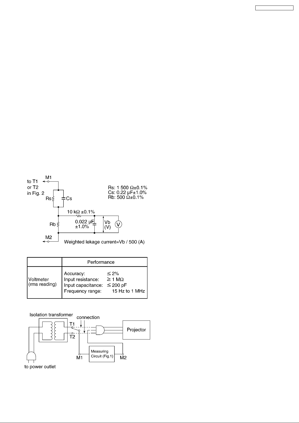
1.2. Leakage Current Check
1. Prepare the measuring circuit as shown in Fig.1.
Be sure to use a voltmeter having the performance
described in Table 1.
3. Connect M1 to T1 according to Fig. 2 and measure the
voltage.
4. Change the connection of M1 from T1 to T2 and measure
the voltage again.
5. The voltmeter must read 0.375 V or lower in both of steps
3 and 4. This means that the current must be 0.75 mA or
less.
6. If the reading is out of the above standard, the projector
must be repaired and rechecked before returning to the
customer because of a possibility of an electric shock.
Fig. 1
Table 1
Fig. 2
2. Assemble the circuit as shown in Fig. 2. Plug the power
cord in a power outlet.
5

PT-D7700U / PT-D7700E
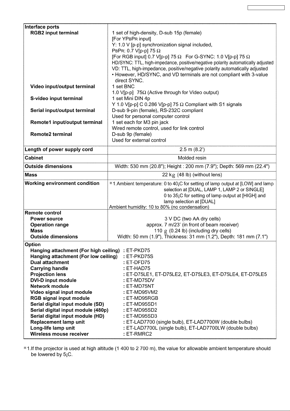
2 Specifications
6
PT-D7700U / PT-D7700E
7
PT-D7700U / PT-D7700E
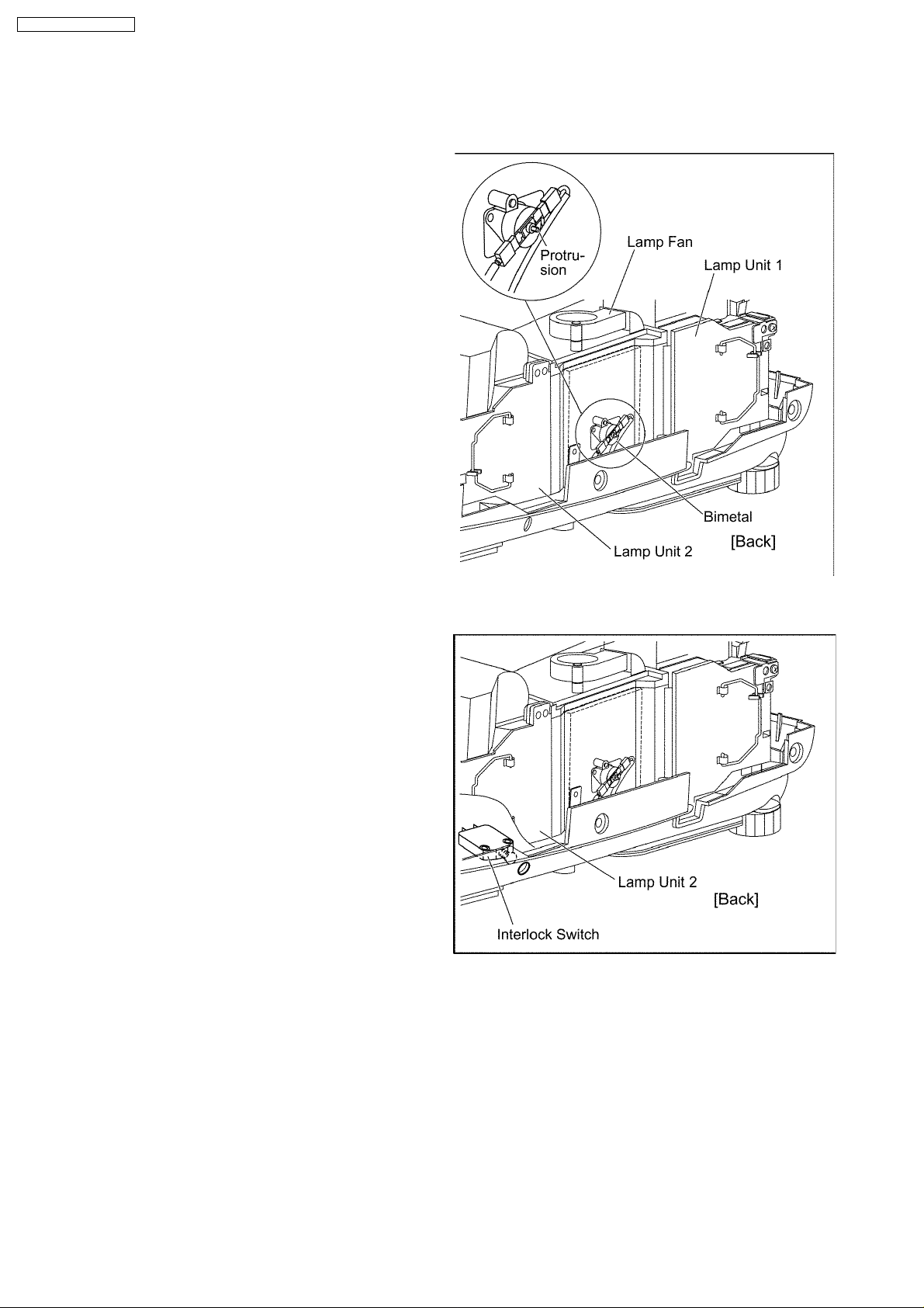
3 Function for Safety
3.1. Temperature Detection inside the Lamp Unit
This projector has a bimetal contacting the lamp units to protect the
lamps.
If the temperature of one of the lamp units exceeds 135 °C, the bimetal
will operate to turn off the power. The installedposition of the bimetal is
shown in the illustration at right.
To reset the bimetal action, press the protrusion of the bimetal until you
feel a click.
3.2. Interlock Switch
To ensure safety, this projector is designed so that the power cannot be
turned on when the rear cover is removed or installed incorrectly.
If removing the rear cover during operation, the power willbe turned off.
8

4 Serviceman Mode
This mode is used to narrow down the location of the failure.
4.1. Setting to Serviceman Mode
(1) Press the MENU button.
The MENU screen will appear.
(2) Select “OPTION” using the or buttons and press the
ENTER button.
TheOPTION screen will appear.
(3) Select “PASSWORD” using the or buttons and press the
ENTER button.
ThePASSWORD screen will appear.
(4) Set the operation mode selector (Computer/Numeric, Projector) switch
to “Computer/Numeric” on the remote control unit and input the
password “1565”.
“ * “ (asterisk)will appear for the password numbers.
(5) Set the operation mode selector (Computer/Numeric, Projector) switch
to “Projector” on the remote control unit and press the ENTER button.
The words “SERVICEMAN MODE” willappear.
PT-D7700U / PT-D7700E
4.2. Resetting to User Mode
(1) Select "PASSWORD" on the OPTION screen using the or
buttons and press the ENTERbutton.
The PASSWORD screen will appear.
(2) Set the operation mode selector (Computer/Numeric, Projector) switch
to "Computer/Numeric" on the remote control unit and input the
password "0000".
" * " (asterisk) will appearfor the password numbers.
(3) Set the operation mode selector (Computer/Numeric, Projector) switch
to "Projector" on the remote control unit and press the ENTER button.
The words "USER MODE" will appear.
9

PT-D7700U / PT-D7700E
4.3. Functions in Serviceman Mode
This projector has functions such as image cutoff and deletion of registered signals by one operation.
[VIDEO menu]
SDI COLOR SELECT
Sets the using mode of the color-difference information in ET-MD95SD2 480P dual link ("MAIN" only or both "MAIN" and
"SUB").
AD LPF
Sets the low pass filter.
[ADVANCED menu]
PLL Setting
Sets VCO and the charge pump.
Frame Lock
Sets the frame lock.
V Mask
Sets the V mask.
[EXTRA OPTION menu]
Cut off
Sets the display on or off for each color (red, green, and blue).
Deletion of Input Signals
Deletes all the registered signals.
REMOTE 2 Setting
Sets the functions of the REMOTE 2 terminal.
· When using the contact control and an optional signal selector in combination, set the pins "No. 3, 4, 5, 6, and 7" of the
REMOTE 2 terminal to OPEN. (When REMOTE 2 Setting is "2", set the pins "No. 3, 4, 5, 6, 7, and 8" of the REMOTE
2terminal to OPEN.)
· When AUX is ET-MD95VM2, the LINE and Y/C selection is set to the last selected condition.
Gamma Selection
Sets the selectable modes of gamma on the VIDEO menu.
STANDARD: You can select the following 5 modes.
"2.2", "2.5", "DEFAULT", "USER 1" and "USER 2"
ALL: You can select the following 13 modes.
"1.0", "1.8", "2.0", "2.2", "2.3", "2.4", "2.5", "2.7", "DEFAULT", "USER 1", "USER 2", "USER 3" and "USER 4"
Fan Full Mode
OFF: Controls the fan speed according to temperature and lamp modes.
ON: Sets the intake fan to the full speed to cool best the power supply and DMD prism, but increases fan noise. At this time,
you cannot select "FAN CONTROL" on the OPTION menu.
Caution:
This mode is for a special usage, usually use it in OFF condition.
10

PT-D7700U / PT-D7700E
Lamp Switching Mute
OFF: Keeps projecting the picture even when switching the lamps.
ON: Stops projecting the picture when switching the lamps.
* If setting to OFF, the picture may be unstable when switching the lamps.
Lamp Relay
"1h", "2h", "3h", "4h" --- "12h":
Turns on lamp1 or lamp 2 alternatively at a selected time interval (1 - 12 hours) when setting the lamp selection to SINGLE.
note:
Use this mode to operate the projector for a long time continuously.
OFF: Stops switching lamp1 and lamp 2.
Power ON Shutter
Open: Opens the shutter when power ON.
Close: Closes the shutter when power ON.
Power OFF Shutter
Open: Opens the shutter when power OFF.
Close: Closes the shutter when power OFF.
Disregard: Does not control the shutter when power OFF.
11
PT-D7700U / PT-D7700E
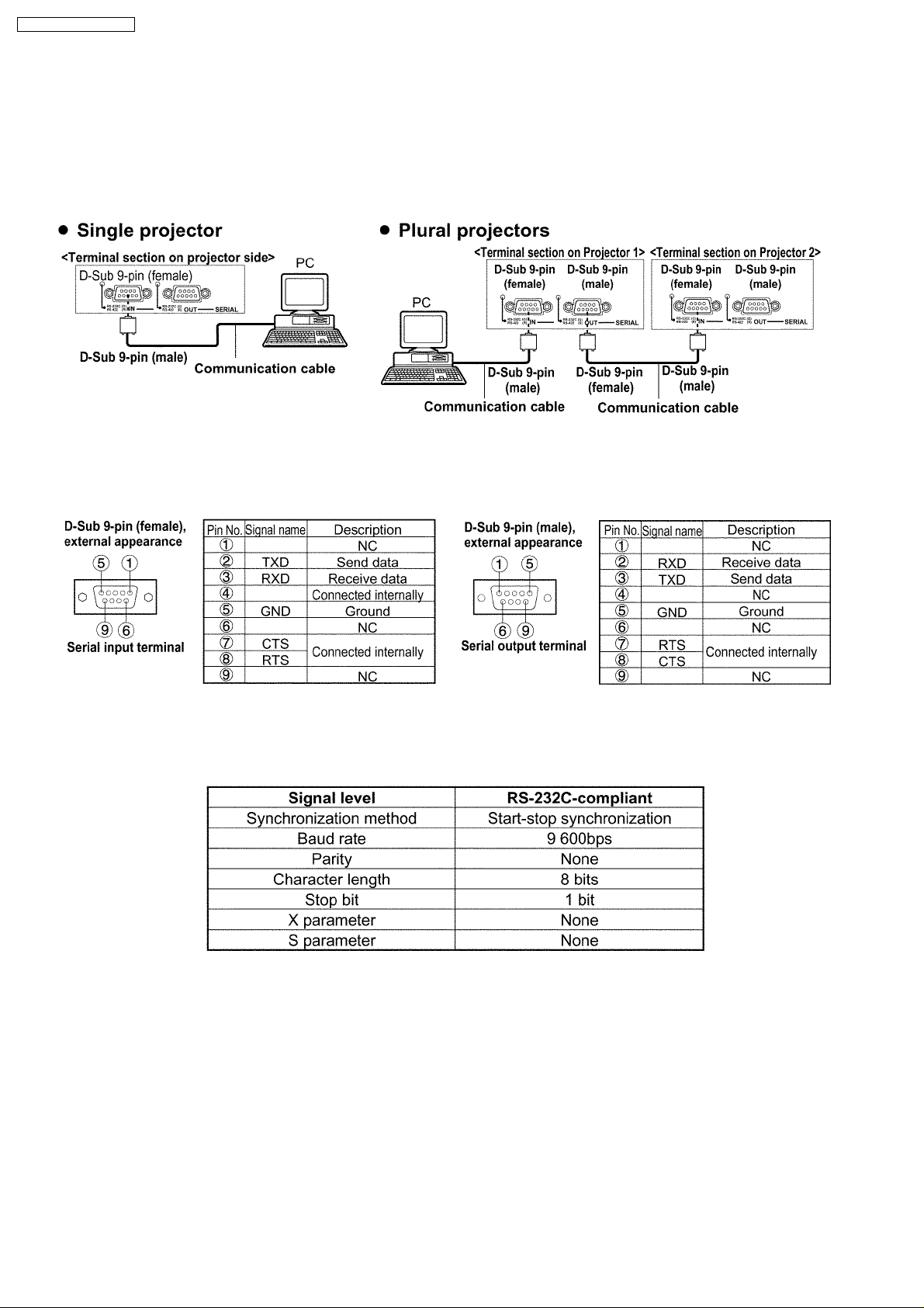
5 Using the Serial Terminals
The main unit is equipped with SERIAL terminals located in its terminal section on the side, and this terminal is compliant with RS232C. Also a serial output terminal is provided to enable plural projector control.
5.1. Examples of Connection
5.2. Pin Assignments and Signal Names
5.3. Communication Conditions (Factory Setting)
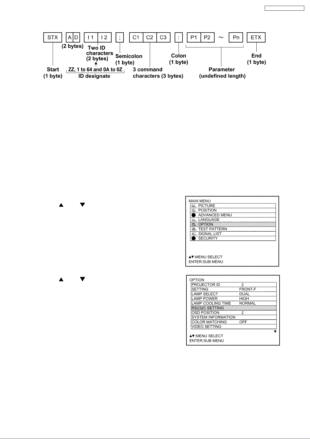
5.4. Basic Format
Transmission from the computer begins with STX, then the ID, command, parameter, and ETX are sent in this order. Add
parameters according to the details of control.
12
PT-D7700U / PT-D7700E
Attention
· No command can be sent or received for 10 to 60 seconds after the lamp starts lighting. Try sending any command after
that period has elapsed.
· When sending several commands, be sure to wait for a response from the projector before sending the next command.
When sending commands without parameters, a colon (:) is not necessary.
Note
· If a wrong command parameter is sent, the projector will send an "ER401" or "ER402" command to the computer.
· A projector ID supported on the RS-232C interface is ZZ (ALL) and a group of 1 to 64 and 0A to 0Z.
· If a command is sent with a projector ID specified, the projector will respond to the computer only in the following cases:
If it coincides with the projector ID,
ID specification is ALL and VPS-SYSTEM is the master, or
ID specification is group and Group is the master.
5.5. Procedure of Communication Condition Settings
(1) Press the MENU button.
The MAIN MENU screen will be displayed.
(2) Press the and buttons to select “OPTION”.
(3) Press the ENTER button.
(4) Press the and buttons to select “RS232C SETTING”.
13

PT-D7700U / PT-D7700E
(5) Press the ENTER button.
The RS232C SETTING screen will be displayed.
(6) Press the and buttons to select communication conditions.
(7) Press the and buttons to confirm the setting..
(8) Press the MENU button three times.
The on-screen indications disappear, and the system returns to the
normal screen.
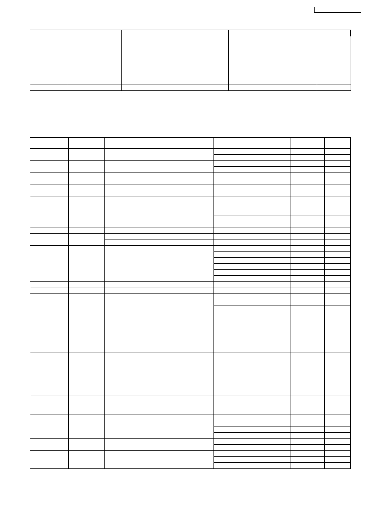
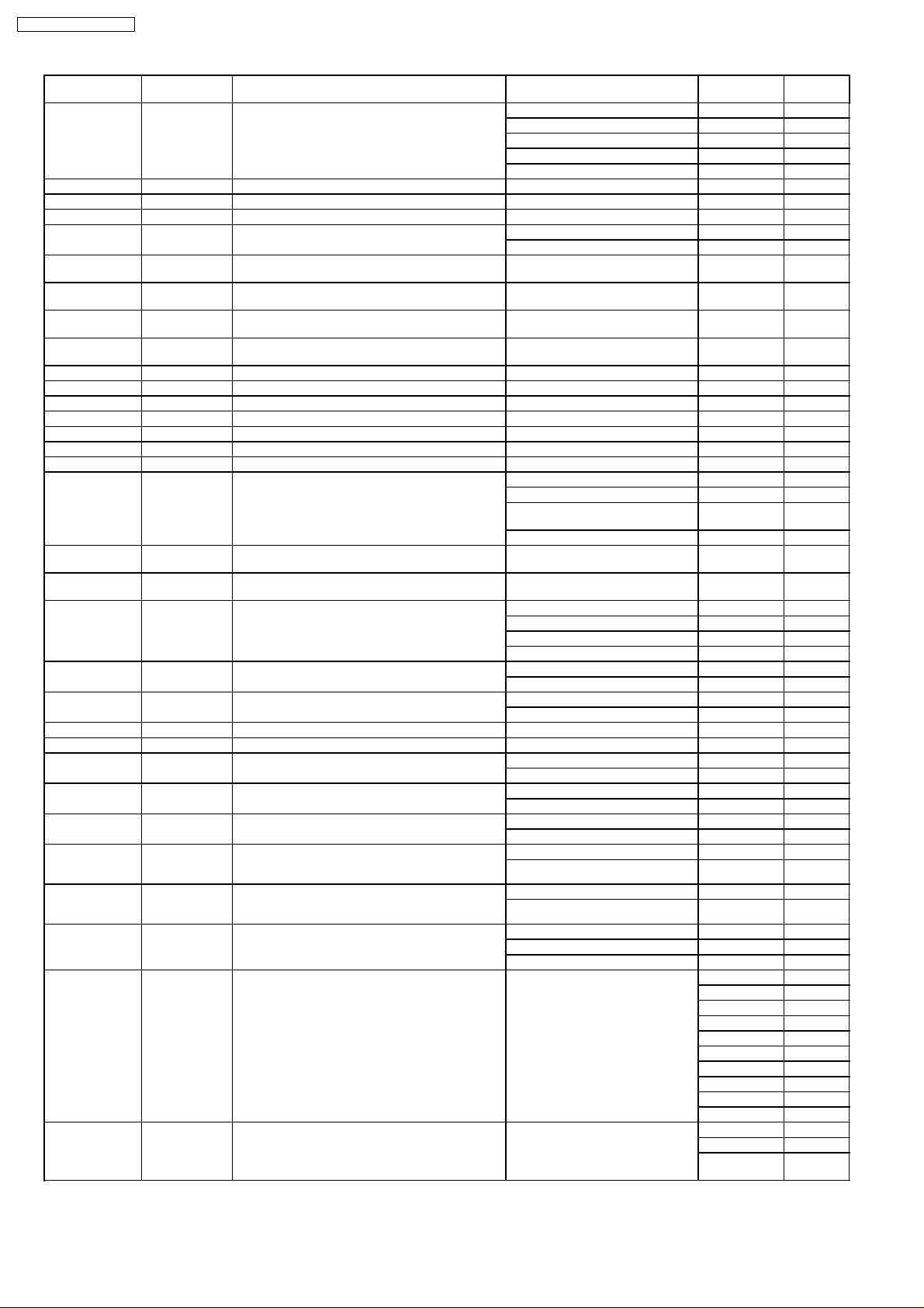
5.6. Control commands
5.6.1. Input Commands
Items Commands:Parameters Functions Callback Remarks
POWER PON POWER ON PON
FREEZE OFZ:0 FREEZE key OFZ:0
MENU OMN MENU key OMN
ENTER OEN ENTER key OEN
CURSOR OCU UP key OCU
STANDARD OST STANDARD key OST
AUTO SETUP OAS AUTO SETUP execution OAS
SHUTTER OSH:0 SHUTTER key OSH:0
INPUT SELECT IIS:RG1 RGB1 IIS:RG1
FUNCTION1 FC1 FUNCTION execution FC1
TEST OTS:p1p2 Test pattern selection OTS:p1p2
ON SCREEN OOS:0 OSD selection OOS:0
NEXT ONX NEXT key ONX
NUMBER KEY ONK:0 NUMBER key 0 ONK:0
SYSTEM SEL OSL SYSTEM SELECTER key OSL
POF STAND-BY POF
OFZ:1 0=OFF 1=ON OFZ:1
OCD DOWN key OCD
OCL LEFT key OCL
OCR RIGHT key OCR
OSH:1 0=OFF 1=ON OSH:1
IIS:RG2 RGB2 IIS:RG2
IIS:VID VIDEO IIS:VID
IIS:SVD S-VIDEO IIS:SVD
IIS:AUX AUX IIS:AUX
00=OFF 01=White picture 02=Black picture
03=Flag
04=Flag inversion 05=1% Window
06=1% Window inversion 07=Focus
08=Colorbar
OOS:1 0= OSD OFF 1=OSD ON OOS:1
ONK:1 NUMBER key 1 ONK:1
ONK:2 NUMBER key 2 ONK:2
ONK:3 NUMBER key 3 ONK:3
ONK:4 NUMBER key 4 ONK:4
ONK:5 NUMBER key 5 ONK:5
ONK:6 NUMBER key 6 ONK:6
ONK:7 NUMBER key 7 ONK:7
ONK:8 NUMBER key 8 ONK:8
ONK:9 NUMBER key 9 ONK:9
5.6.2. Data setting Commands
Items Commands:Parameters Functions Callback Remarks
ID SET RIS:p1p2 Projector ID setting RIS:p1p2 *1
INSTALLATION OIL:0 Front/Floor OIL:0
LAMP SELECT LPM:0 Lamp selection LPM:0 *2
OIL:1 Rear/Floor OIL:1
OIL:2 Front/Ceiling OIL:2
OIL:3 Rear/Ceiling OIL:3
LPM:1 0=DUAL 1=SINGLE LPM:1
LPM:2 2=LAMP1 3=LAMP2 LPM:2
LPM:3 LPM:3
14
PT-D7700U / PT-D7700E
Items Commands:Parameters Functions Callback Remarks
LAMP POWER OLP:0 LAMP POWER setting OLP:0
SUB MEMORY OCS:p1p2 SUB MEMORY switching OCS:p1p2 *1
SET DATE TSD:y1y2y3y4
SET TIME TST:h1h2m1m2s1s2 Time setting TST:h1h2m1m2s1s2 *3
OLP:1 0=HIGH 1=LOW OLP:1
m1m2d1d2w
Date setting TSD:y1y2y3y4m1m2d1d2w y1y2y3y4m1m2
*1 The input of p1p2 accepts any of the types +1, +01, 1 and 01.
*2 In the SINGLE mode, one of lamp 1 and lamp 2 whose remainder time is longer is turned ON.
*3 Displays of SET DATE and SET TIME are set by UTC (Coordinated Universal Time).
5.6.3. Inquiry Commands
d1d2 + a day
of the week
(Mon.=1
Tues.=2 --Sun.=7) *3
Items Commands:Para
POWER
CONDITION
FREEZE QFZ Inquiry about freeze 0 OFF
SHUTTER QSH Inquiry about shutter 0 OFF
AUTO SETUP QAS Inquiry about auto setup 0 In Process
INPUT SIGNAL QIN Inquiry about input channel RG1 RGB-1
TEST QTS Inquiry about test pattern p1p2
ON SCREEN QOS Inquiry about on screen display 0 off
PICTURE MODE QPM Inquiry about picture mode NAT NATURAL
COLOR QVC Inquiry about color p1p2p3
TINT QVT Inquiry about tint p1p2p3
COLOR TEMP. QTE Inquiry about color temperature 0 LOW
WHITE BALANCE
LOW(R)
WHITE BALANCE
LOW(G)
WHITE BALANCE
LOW(B)
WHITE BALANCE
HI(R)
WHITE BALANCE
HI(G)
WHITE BALANCE
HI(G)
CONTRAST QVR Inquiry about contrast p1p2p3
BRIGHTNESS QVB Inquiry about brightness p1p2p3
SHARPNESS QVS Inquiry about sharpness p1p2p3
NOISE
REDUCTION
DYNAMIC IRIS QAI Inquiry about DYNAMIC IRIS 0 OFF
DIGITAL CINEMA
REALITY
meters
QPW Inquiry about power 000 OFF
QOR Inquiry about white balance low (R) p1p2p3
QOG Inquiry about white balance low (G) p1p2p3
QOB Inquiry about white balance low (B) p1p2p3
QHR Inquiry about white balance high (R) p1p2p3
QHG Inquiry about white balance high (G) p1p2p3
QHB Inquiry about white balance high (B) p1p2p3
QNS Inquiry about noise reduction 0 OFF
QPD Inquiry about DIGITAL CINEMA REALITY 0 AUTO
Functions Callback InterpretationRemarks
001 ON
1 ON
1 ON
1 In Stop
RG2 RGB-2
VID VIDEO
SVD S-VIDEO
AUX AUX
1 on
STD STANDARD
DYN DYNAMIC
CIN CINEMA
GRA GRAPHIC
USR USER
1 MIDDLE
2 HIGH
4 USER1
9 USER2
10 DEFAULT
1 1
2 2
3 3
1 ON
1 OFF
2 2:2 ON
15
PT-D7700U / PT-D7700E
Items Commands:Para
COLOR MATCHING QMC Inquiry about color matching 0 OFF
ZOOM(H) QZH Inquiry about horizontal magnification p1p2p3
ZOOM(V) QZV Inquiry about vertical magnification p1p2p3
ZOOM (H/V) QZO Inquiry about magnification p1p2p3
ZOOM (H/V gang
control)
BLANKING
(UPPER)
BLANKING
(LOWER)
BLANKING
(LEFT)
BLANKING
(RIGHT)
CLOCK PHASE QCP Inquiry about clock phase p1p2p3
TOTAL DOTS QTD Dot count p1p2p3p4
DISPLAY DOTS QDD Dot count for display p1p2p3p4
TOTAL LINES QTL Line count p1p2p3p4
DISPLAY LINES QDL Line count for display p1p2p3p4
KEYSTONE QKS Inquiry about trapezoidal correction p1p2p3
LINEARITY QLI Inquiry about trapezoidal linearity p1p2p3
INSTALLATION QSP Inquiry about installed condition 0 Front/Floor
SET RUNTIME QST Inquiry about uptime p1p2p3p4p5 00000h to
LAMP ON TIME
(LAMP TIMER)
LAMP SELECT QSL Inquiry about lamp selection 0 DUAL
LAMP POWER QLP Inquiry about lamp power selection 0 HIGH
VPS SYSTEM QVY Inquiry about VPS system 0 SLAVE
GROUP GET ADa1a2;QRG Group acquisition ADa1a2;RGSg1g2
MASTER GET ADg1g2;QRL Group leader acquisition ADa1a2;RLSa1a2
VIDEO SELECT QM1 Inquiry about ET-MD95VM2 board input 0 LINE or Y/C
VIDEO SYSTEM
(VIDEO)
VIDEO SYSTEM
(S-VIDEO)
VIDEO SYSTEM
(ET-MD95VM2
board LINE)
VIDEO SYSTEM
(ET-MD95VM2
board Y/C)
AUTOSETUP MODE QAM Inquiry about auto setup mode 0 USER
INPUT BOARD QIB Inquiry about input board p1p2p3p4 --- (indefinite
TEMPERATURE QTM:p1 Readout of temperature data p1p2p3p4/p5p6p7p8
meters
QZS Inquiry about gang control for zoom 0 OFF
QLU Inquiry about blanking (upper) p1p2p3
QLB Inquiry about blanking (lower) p1p2p3
QLL Inquiry about blanking (left) p1p2p3
QLR Inquiry about blanking (right) p1p2p3
Q$L:p1 (p1 =
1or2)
QY1 Inquiry about Video system (VIDEO) AT1 AUTO1
QY2 Inquiry about Video system (S-VIDEO) AT1 AUTO1
QY3 Inquiry about video system (ET-MD95VM2
QY4 Inquiry about video system (ET-MD95VM2
Inquiry about lamp-on time (1=lamp 1
2=lamp 2)
board LINE)
board Y/C))
Functions Callback InterpretationRemarks
1 3COLORS
2 7COLORS
3 MEASURE
4 PC
1 ON
1 Rear/Floor
2 Front/Ceilin
3 Rear/Ceiling
p1p2p3p4 0000h to
1 SINGLE
2 LAMP1
3 LAMP2
1 LOW
1 MASTER
1 YCbCr
AT2 AUTO2
AT2 AUTO2
AT1 AUTO1
AT2 AUTO2
AT1 AUTO1
AT2 AUTO2
1 STANDARD
2 WIDE
length)
(Centigrade/Fahrenheit)
g
99999h
MD95VM2
MD95SD1
MD95SD2
MD95SD3
MD95RGB
MD75NT
MD75DV
NONE
UNKNOWN
NOT SUPPORT
p1=0 intake
p1=1 exhaust
p1=2 optical
module
9999h
16
PT-D7700U / PT-D7700E
Items Commands:Para
PinP QPP Inquiry about P in P on/off 0 OFF
FUNCTION1 QFC Inquiry about function 1 0 PinP
SUB MEMORY QSB Inquiry about sub memory p1p2
GET DATE QGD Inquiry about date y1y2y3y4m1m2d1d2w yyyymmdd (a
GET TIME QGT Inquiry about time h1h2m1m2s1s2 hhmmss
meters
Functions Callback InterpretationRemarks
1 USER1
2 USER2
3 USER3
1 LAMP POWER
2 SIZE
day of the
week)
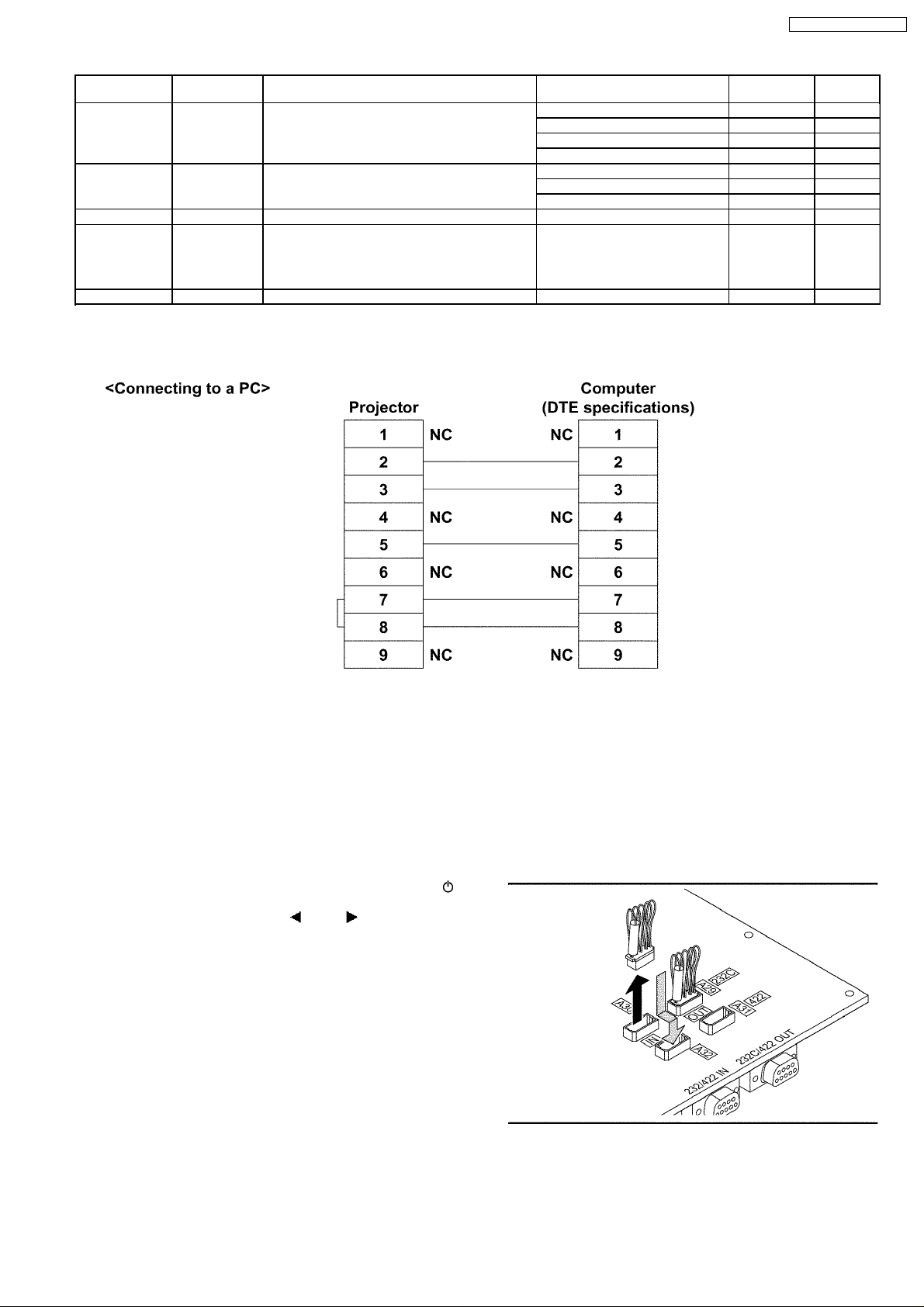
5.7. Cable specifications
Adayof
the week:
Mon.=1
Tues.=2 -
-- Sun.=7
Note
To connect the computer to the SERIAL terminal, prepare an adequate communication cable that fits to your personal
computer.
5.8. Converting to RS-422 Control Functions
The RS-232C terminal of the projector is available as a RS-422 control terminal. The factory default setting is RS-232C control
terminal.
Converting the RS-232C-IN terminal to RS-422-IN terminal
(1) If the power of the projector is on, press the POWER OFF ( ) button
on the remote control unit or projector.
(2) Select "EXECUTE" using the or buttons and press the
ENTER button.
Wait aboutfive minutes until the cooling fans stop.
(3) Turn off the MAIN POWER switch on the projector and unplug the power
cord from the outlet.
(4) Follow "11.3" to remove the upper cover.
(5) Remove the connector inserted into A30 on the A-P.C.Board and insert
it into A32.
(6) Install the upper cover.
17

PT-D7700U / PT-D7700E
(7) Plug the projector to the outlet and turn on the MAIN POWER switch.
(8) Check that the indicator lamp at the left of the RS-232-IN terminal
illuminates in red.
Returning the RS-232C-IN terminal to RS-232C-IN terminal
(1) If the power of the projector ison, press the POWER OFF ( ) button
on the remote control unit or projector.
(2) Select "EXECUTE" using the or buttons and press the
ENTER button.
Wait aboutfive minutes until the cooling fans stop.
(3) Turn off the MAIN POWER switch on the projector and unplug the power
cord from the outlet.
(4) Follow "11.3" to remove the upper cover.
(5) Remove the connector inserted into A32 on the A-P.C.Board and insert
it into A30.
(6) Install the upper cover.
(7) Plug the projector to the outlet and turn on the MAIN POWER switch.
(8) Check that the indicator lamp at the left of the RS-232-IN terminal
illuminates in green.
Converting the RS-232C-OUT terminal to RS-422-OUT terminal
(1) If the power of the projector is on, press the POWER OFF ( ) button
on the remote control unit or projector.
(2) Select "EXECUTE" using the or buttons and press the
ENTER button.
Wait aboutfive minutes until the cooling fans stop.
(3) Turn off the MAIN POWER switch on the projector and unplug the power
cord from the outlet.
(4) Follow "11.3" to remove the upper cover.
(5) Remove the connector inserted into A29 on the A-P.C.Board and insert
it into A31.
(6) Install the upper cover.
(7) Plug the projector to the outlet and turn on the MAIN POWER switch.
(8) Check that the indicator lamp at the left of the RS-232-IN terminal
illuminates in red.
Returning the RS-232C-OUT terminal to RS-232C-OUT terminal
(1) If the power of the projector ison, press the POWER OFF ( ) button
on the remote control unit or projector.
18

(2) Select "EXECUTE" using the or buttons and press the
ENTER button.
Wait aboutfive minutes until the cooling fans stop.
(3) Turn off the MAIN POWER switch on the projector and unplug the power
cord from the outlet.
(4) Follow "11.3" to remove the upper cover.
(5) Remove the connector inserted into A31 on the A-P.C.Board and insert
it into A29.
(6) Install the upper cover.
(7) Plug the projector to the outlet and turn on the MAIN POWER switch.
(8) Check that the indicator lamp at the left of the RS-232-IN terminal
illuminates in green.
Pin Assignments in the RS-422 Control Mode
PT-D7700U / PT-D7700E
19
PT-D7700U / PT-D7700E
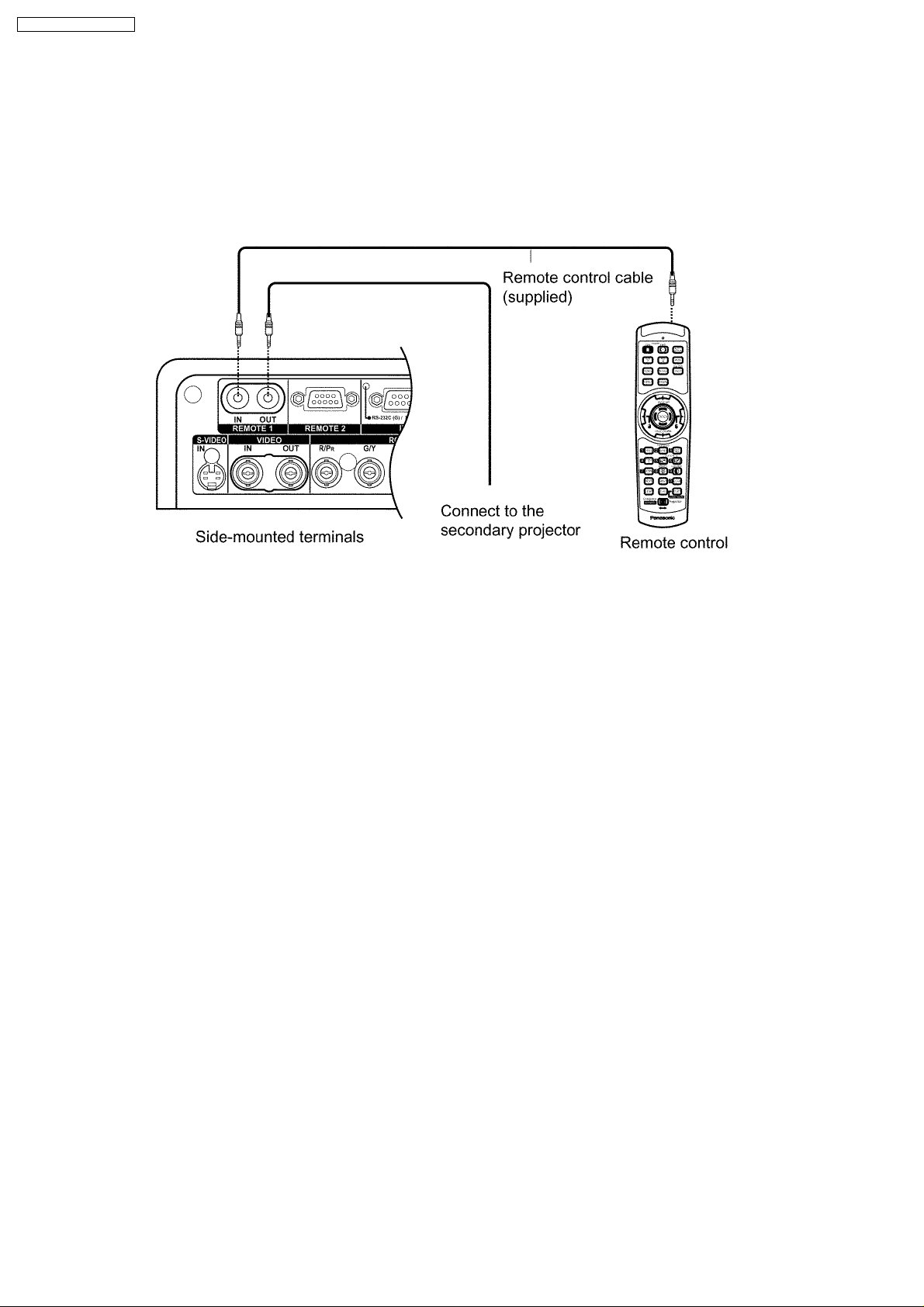
6 Using a Wired Remote Control
6.1. Connection Example
When two or more projectors are connected in the system, connect the projectors with the supplied remote control cable to
simultaneously control the projectors with a remote control unit through the REMOTE1 IN/OUT terminal. It is effectiveto use the
wired remote control in the environment in which an obstacle stands in the light path or where the system is susceptible to outside
light.
6.2. Setting the Projector ID Number for Remote Control
Every projector has its ID number and the ID number of the controlling projector must be set to the remote control in advance so
that the user can operate the remote control. The ID number of the projector is set to “ALL” on shipping,and use the ID ALL button
of the remote control when using only one projector.
Procedure of ID setting
Press the ID SET button, and within five seconds, use the NEXT button to set the number of the ten place in the ID number,
which is already set in the projector, and then use one of the numeric (0-9) buttons to set the number of the one
place.However,if the ID ALL button is pressed, the projector can be controlled regardless of the ID number of the projector
(simultaneous control mode).
· If the ID SET button is pressed, the ID number goes back to the one set before pressing the ID SET button unless the NEXT
button and a numeric button are pressed within five seconds after the ID SET button is pressed.
· Do not press the ID SET button accidentally or carelessly because the ID number on the remote control can be set even
when no projector is around.
· Your specified ID number is stored in the remote control unit unless another one is specified later. However, the stored ID
will be erased if the batteries of the remote control are left exhausted. When the dry cells are replaced, setthe same ID
number again.
20

PT-D7700U / PT-D7700E
7 Support for Service
7.1. Supporting Methods
We will support according to the following methods.
Supporting methods Applied parts
Replaced by module or block Ballast power supply
Replaced by discrete components Other components
Replacd at the manufacturing
department
7.2. Note for Replacement of P.C.Boards
7.2.1. When replacing the A-P.C.Board
· Transfer the data of the original A-P.C.Board to the new A-P.C.Board using the adjustment software and a personal computer.
(If you cannot transfer the data, remove IC2611, IC2618, and IC2619 from the original board and mount them on thenew
board.)
* For the adjustment software, consult an authorized service center.
7.2.2. When replacing the X-P.C.Board
· Be sure to turn off the MAIN POWER switch before removing the X-P.C.Board. If replacing this board during standby condition,
the projector may suffer damage.
· After replacing the X-P.C.Board, no adjustment is necessary.
Optical block unit (including DMD™ devices) [FM] DMD™ drive module
7.3. Service Kit (Extension Board) for X-P.C.Board
To check the X-P.C.Board during operation, a service kit is necessary. (Part number: TZSH07011)
* Consult an authorized service center to get the service kit.
Connecting the jig
(1) Unscrew the 6 screws on the right side and remove the terminal
cover.
(2) Unscrew the 2 screws and remove the slot cover.
(3) Unscrew the 5 screws and 8 hex-head screws, remove the terminal
plate.
21
PT-D7700U / PT-D7700E
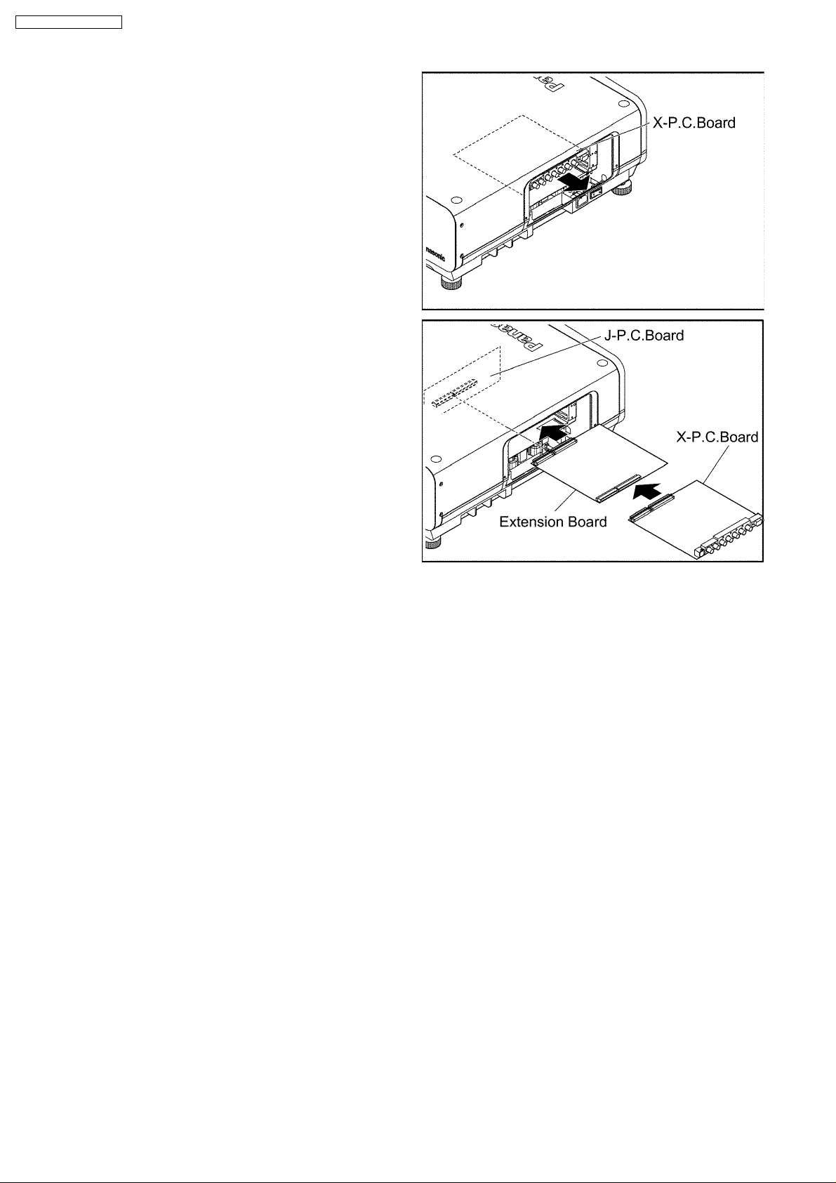
(4) Slide out the X-P.C.Board to disconnect it from the connectors on the
J-P.C.Board.
(5) Instead of the X-P.C.Board, connect the extension board into the
connector on the J-P.C.Board.
(6) Connect the X-P.C.Board to the connector on the extension board.
7.4. Replacement of the lithium battery on the R-P.C.Board
If the lithium battery will be empty, replace it with a new one (CR2032 or equivalent).
Cautions
· Explosion may occur if replacing the battery with an incorrect one.
· Dispose of used batteries according to the instructions.
22

PT-D7700U / PT-D7700E
8 Cautions for Service
· Never unplug the power cord from the outlet, open the circuit breaker, or perform other procedures to cut off the power line
during the operation of any cooling fan.
To turn off the projector, press the POWER OFF (
minutes until the cooling fans stop (The power indicator lamp onthe projector illuminates in orange).
· Be sure to check that the cooling fans have stopped (The power indicator lamp illuminates in red). After that, turn off the
MAIN POWER switch.
· This projector emits strong light, so never look into the lens. If doing so, your eyes can suffer damage.
) button on the remote control unit or projector and wait about four
23
PT-D7700U / PT-D7700E
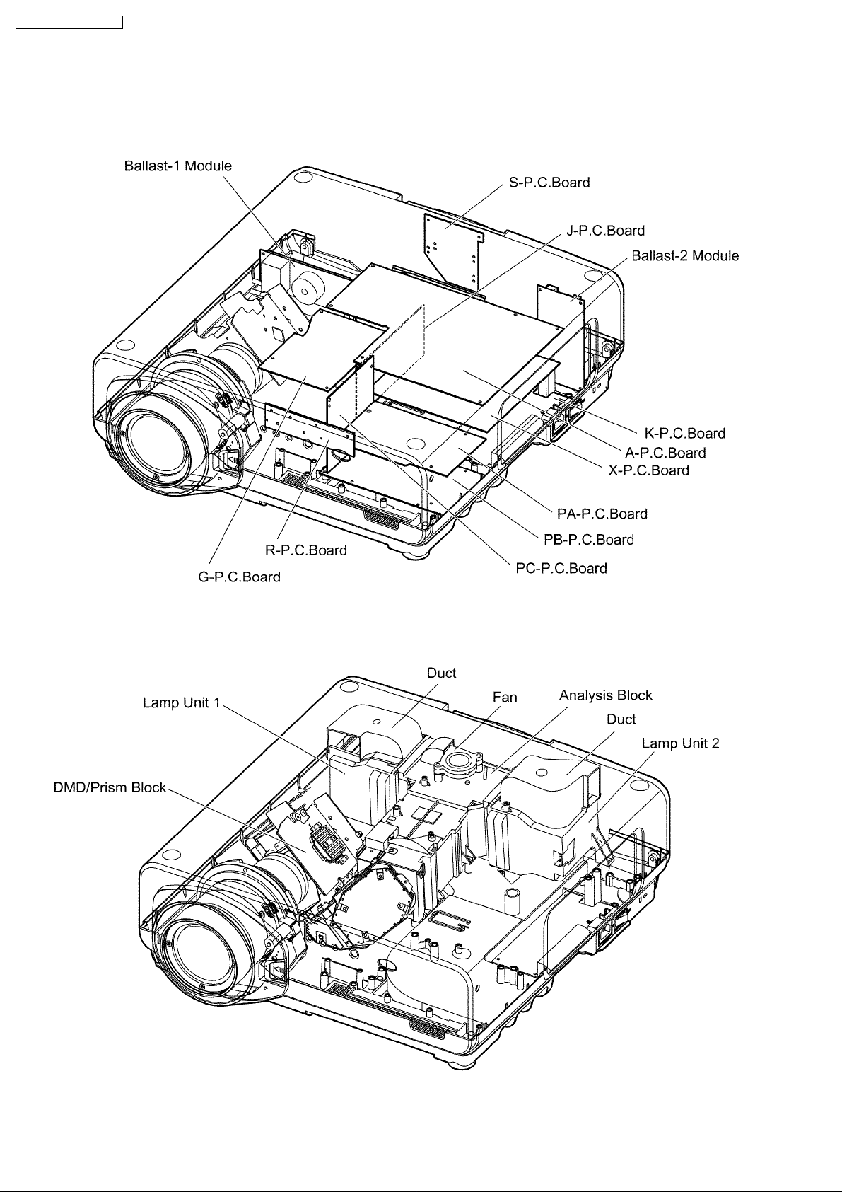
9 Parts Location
9.1. Electrical Parts Location
9.2. Electromechanical Parts Location
24
PT-D7700U / PT-D7700E
10 Replacement of Lamp Unit
Cautions
· Wait until the lamp is cooled sufficiently before replacing the lamp unit.
10.1. Precautions on Lamp Unit Replacement
· Be careful when handling a light source lamp . The lamp may burst if it hit by solid objects or if it is dropped because of high
air pressure inside the bulb.
· A used lamp unit may burst if it is handled violently.
For disposition of used lamps, request an industrial waste disposal contractor.
· Do not reset the cumulative time, except when the lamp unit has been replaced with a new unit.
· If you continue to use a lamp after the replacement time, the lamp may break.
· Philips screwdriver is necessary when replacing a lamp unit.
Take care not to slip your hand when using a screwdriver.
· A lamp unit is an optional part. Contact the dealer.
Replacement lamp unit model No.: ET-LAD7700 (single bulb), ET-LAD7700W (double bulbs)
Rating: 300 W 80 V
Long-life lamp unit model No.: ET-LAD7700L (single bulb), ET-LAD7700LW (double bulbs)
Rating: 160 W 80 V
· Other lamps than specified above cannot be used. Be sure to use the specified lamp.
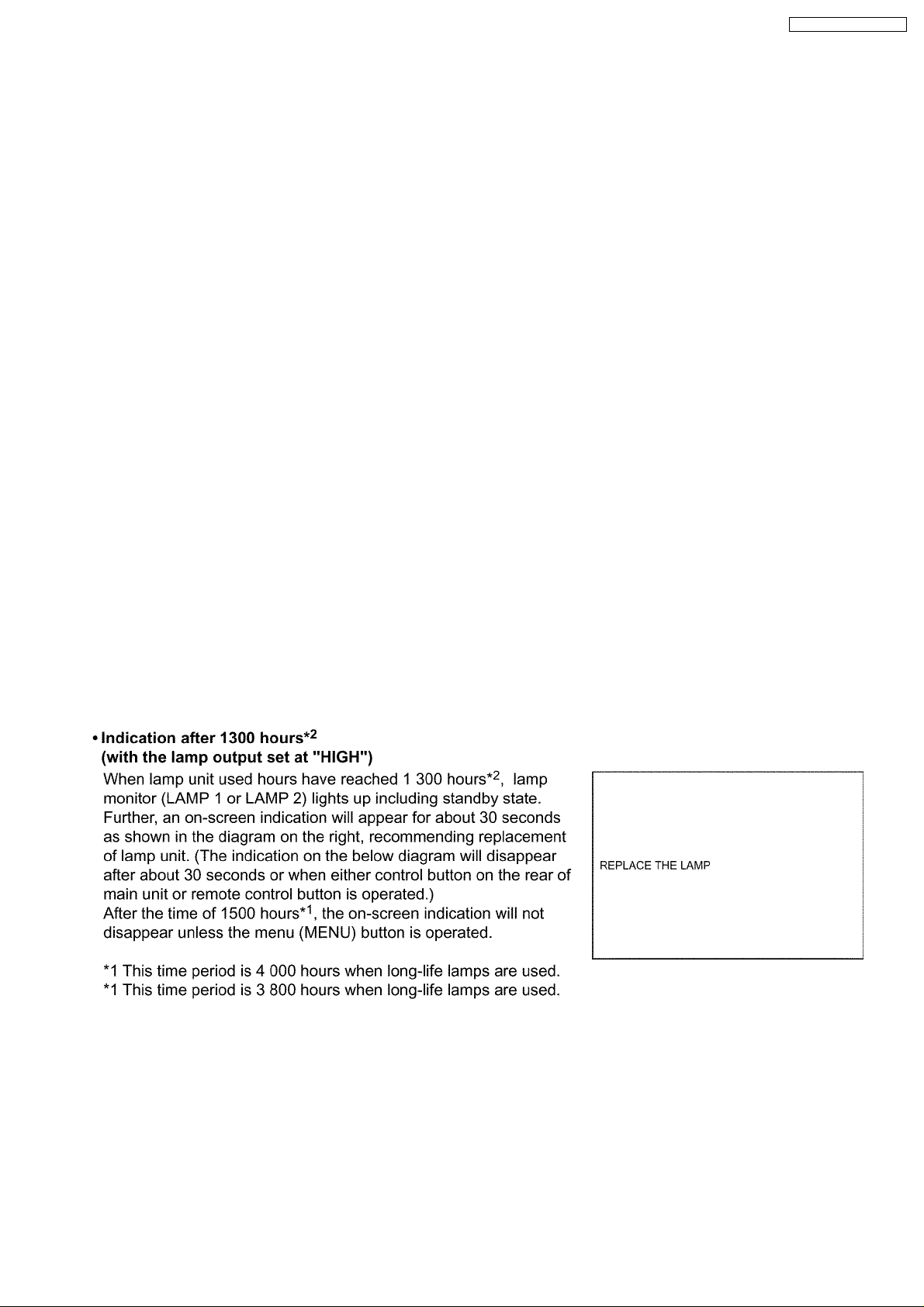
10.2. Timing of Lamp Unit Replacement
The lamp used for the light source has its due life. The life of light source lamp used in the main unit is 1 500 hours*1(when lamp
output is HIGH and lamp selection is DUAL). However, it may happen that the lamp becomes dead(will not light) by the time of 1
500 hours
the times of lighting and the intervals between previous lighting andnext lighting). Therefore, it is strongly recommended for the user
to keep a spare bulb. If your lamp unit is not replaced after 1 300 hours
be turned offautomatically at the time of 1 500 hours
later, entering a standby state even if it is turned on again.
*1
depending on the characteristics of individual lamps and working conditions (lamps may reduce their life affected by
*2
*1
of initial lighting, power supply is turned off automatically about 10 minutes
(with the lamp output set at “HIGH”), power supply will
25

PT-D7700U / PT-D7700E
10.3. Lamp Monitor
26
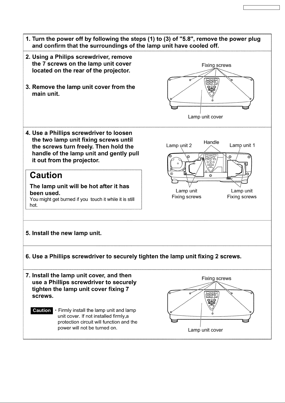
10.4. Procedure of Lamp Unit Replacement
PT-D7700U / PT-D7700E
NOTE:
· Be sure to follow steps 8 to 15 in ten minutes after turning on the projector because the projector is turned off in ten minutes
if the RUNTIME indication is 1 500h or more.
27

PT-D7700U / PT-D7700E
28
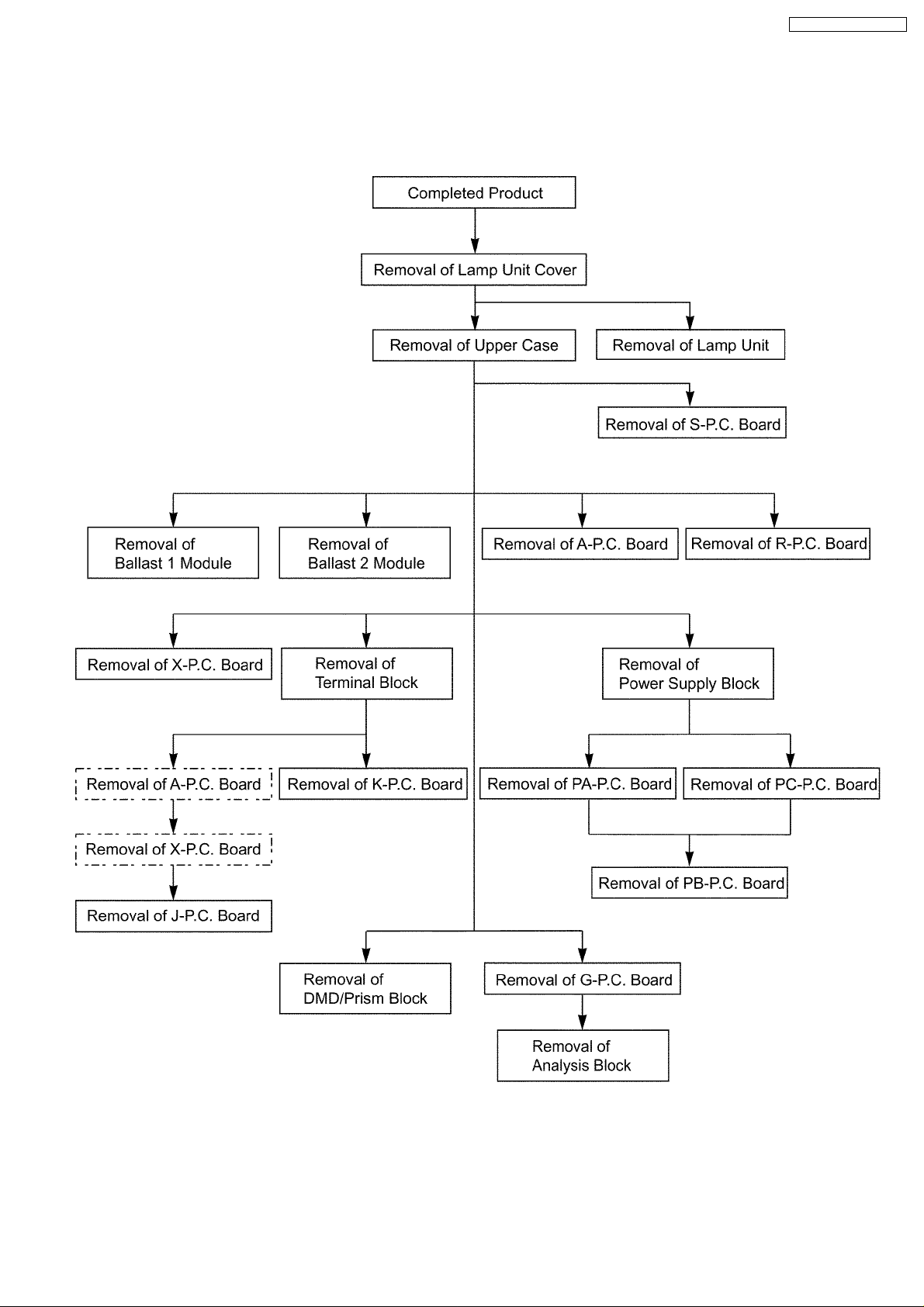
11 Disassembly Instructions
11.1. Flowchart for Disassembly
To assemble, reverse the disassembly procedures.
PT-D7700U / PT-D7700E
29

PT-D7700U / PT-D7700E
11.2. Air Filter Cleaning
(1) Pull out the air filter to remove it.
(2) Clean the air filter using a vacuum cleaner.
11.3. Removal of Upper Cover
(1) Unscrew the 7 screws and remove the lamp unit cover.
(2) Unscrew the 6 screws on the right side and remove the terminal
cover.
(3) While pressing the projection lens cover lock button, pull the
projection lens cover in the direction right side front to remove
it.
Note:
· Be careful not to damage the tab on the left side of the
projection lens cover.
30
 Loading...