

Panasonic PT-D5500U, PT-D5500E, PT-D5500UL, PT-D5500EL Service Manual
DLP™ Based Projector
PT-D5500U
PT-D5500E
PT-D5500UL
PT-D5500EL
ORDER NO. VED0409358C0
D10
© 2004 Matsushita Electric Industrial Co., Ltd. All
rights reserved. Unauthorized copying and
distribution is a violation of law.
PT-D5500U / PT-D5500E / PT-D5500UL / PT-D5500EL
2

PT-D5500U / PT-D5500E / PT-D5500UL / PT-D5500EL
CONTENTS
Page Page
1 Safety Precautions 4
1.1. General Guidelines
1.2. Leakage Current Check
2 Specifications
3 Function for Safety
3.1. Interlock Switch
4 Serviceman Mode
4.1. Setting to Serviceman Mode
4.2. Resetting to User Mode
4.3. Functions in Serviceman Mode
5 Using the Serial Terminals
5.1. Examples of Connection
5.2. Pin Assignments and Signal Names
5.3. Communication Conditions (Factory Setting)
5.4. Basic Format
5.5. Procedure of Communication Condition Settings
5.6. Control commands
5.7. Cable specifications
6 Using a Wired Remote Control
6.1. Connection Example
6.2. Setting the Projector ID Number for Remote Control
7 Support for Service
7.1. Supporting Methods
7.2. Note for Replacement of P.C.Boards
7.3. Replacement of the lithium battery on the A-P.C.Board
8 Cautions for Service
8.1. Servicing Methods
9 Parts Location
9.1. Electrical Parts Location
9.2. Electromechanical Parts Location
10 Replacement of Lamp Unit
10.1. Precautions on Lamp Unit Replacement
10.2. Timing of Lamp Unit Replacement
10.3. Indication of Lamp Monitor
10.4. Procedure of Lamp Unit Replacement
11 Disassembly Instruction s
11.1. Flowchart for Disassembly
11.2. Removal of Upper Case
11.3. Removal of A-P.C.Board
11.4. Removal of J-P.C.Board
11.5. Removal of D-P.C.Board
11.6. Removal of Power Module
14
14
14
14
14
15
16
19
20
20
20
21
21
21
21
21
21
22
22
22
23
23
23
24
24
27
27
28
28
29
29
30
11.7. Removal of R-P.C.Board
4
4
5
7
7
7
7
8
9
11.8. Removal of S-P.C.Board
11.9. Removal of Ballast-1 and Ballast-2 Modules
11.10. Removal of Lamp Unit
11.11. Removal of Projection Lens
11.12. Removal of Analysis Block
11.13. Removal of Synthesis Mirror
11.14. Removal of Color Wheel Block (Analysis Block)
11.15. Removal of Rod (complete)
11.16. Removal of Full Reflection Mirror (complete)
11.17. Removal of DMD Block (complete)
12 Troublesh ooting
13 Interconne ction Block Diagram
13.1. Interconnection Block Diagram (1/3)
13.2. Interconnection Block Diagram (2/3)
13.3. Interconnection Block Diagram (3/3)
14 Block Diagram
14.1. Power Supply
14.2. Signal Processing (1/2)
14.3. Signal Processing (2/2)
14.4. Fan/Motor Drive
15 Schematic Diagram
15.1. A-P.C.Board (1/11)
15.2. A-P.C.Board (2/11)
15.3. A-P.C.Board (3/11)
15.4. A-P.C.Board (4/11)
15.5. A-P.C.Board (5/11)
15.6. A-P.C.Board (6/11)
15.7. A-P.C.Board (7/11)
15.8. A-P.C.Board (8/11)
15.9. A-P.C.Board (9/11)
15.10. A-P.C.Board (10/11)
15.11. A-P.C.Board (11/11)
15.12. CW/D/R/S-P.C.Board
15.13. J-P.C.Board
16 Circuit Boards
16.1. A-P.C.Board (Foil Side)
16.2. A-P.C.Board (Component Side)
16.3. J-P.C.Board
17 Terminal guide of ICs and transistors
18 Exploded Views
19 Replacement Parts List
30
30
31
33
34
34
35
36
36
37
37
38
49
49
50
51
53
53
54
55
56
57
58
59
60
61
62
63
64
65
66
67
68
69
70
71
71
72
73
75
76
80
3
PT-D5500U / PT-D5500E / PT-D5500UL / PT-D5500EL
1 Safety Precautions
1.1. General Guidelines
· For continued safety, no modification of any circuit must be
attempted.
· Unplug the power cord from the power outlet before
disassembling this projector.
· It is advisable to use an isolation transformer in the AC
power line before the service.
· Observe the original lead dress during the service. If a short
circuit is found, replace all the parts overheated or
damaged by the short circuit.
· After the service, all the protective devices such as
insulation barriers, insulation papers, shields, and isolation
R-C combinations must be properly installed.
· After the service, check the leakage current to prevent the
customer from getting an electric shock.
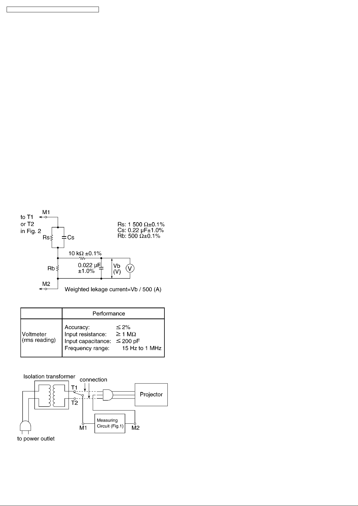
1.2. Leakage Current Check
1. Prepare the measuring circuit as shown in Fig.1.
Be sure to use a voltmeter having the performance
described in Table 1.
3. Connect M1 to T1 according to Fig. 2 and measure the
voltage.
4. Change the connection of M1 from T1 to T2 and measure
the voltage again.
5. The voltmeter must read 0.375 V or lower in both of steps
3 and 4. This means that the current must be 0.75 mA or
less.
6. If the reading is out of the above standard, the projector
must be repaired and rechecked before returning to the
customer because of a possibility of an electric shock.
Fig. 1
Table 1
Fig. 2
2. Assemble the circuit as shown in Fig. 2. Plug the power
cord in a power outlet.
4
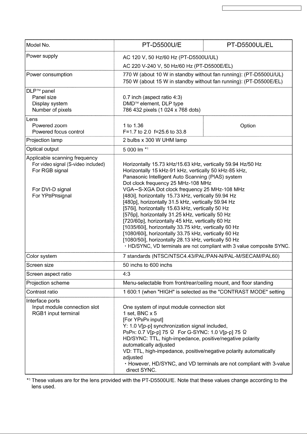
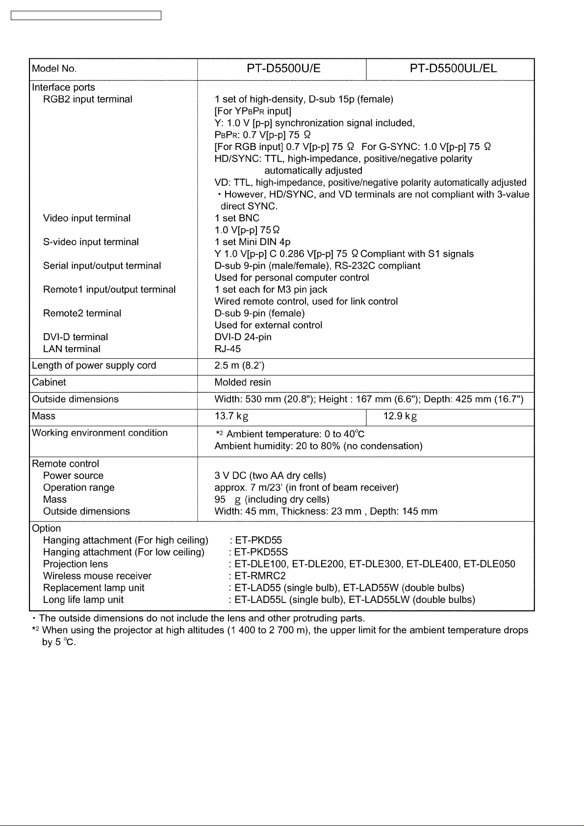
2 Specifications
PT-D5500U / PT-D5500E / PT-D5500UL / PT-D5500EL
5
PT-D5500U / PT-D5500E / PT-D5500UL / PT-D5500EL
6
3 Function for Safety
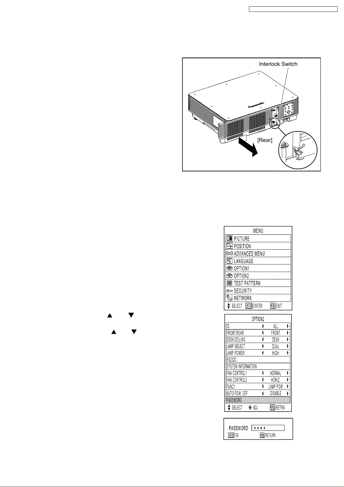
3.1. Interlock Switch
To ensure safety, the protection circuit of the main unit functions, and
this projector becomes operation halt condition (a part of circuit is
energizing) when the lamp unit cover is removed or installed incorrectly.
PT-D5500U / PT-D5500E / PT-D5500UL / PT-D5500EL
4 Serviceman Mode
This projector has Serviceman Mode in addition to standard on-screen menus (User Mode).
4.1. Setting to Serviceman Mode
(1) Press the MENU button.
The MENU screen will appear.
(2) Select “OPTION2” using the or buttons and press the
ENTER button.
The OPTION2 screen will appear.
(3) Select “PASSWORD” using the or buttons and press the
ENTER button.
The PASSWORD screen will appear.
(4) Set the operation mode selector (Computer/Numeric, Projector) switch
to “Computer/Numeric” on the remote control unit and input the
password “1565”.
Note:
· Asterisk (*) will appear for the password numbers.
7
PT-D5500U / PT-D5500E / PT-D5500UL / PT-D5500EL
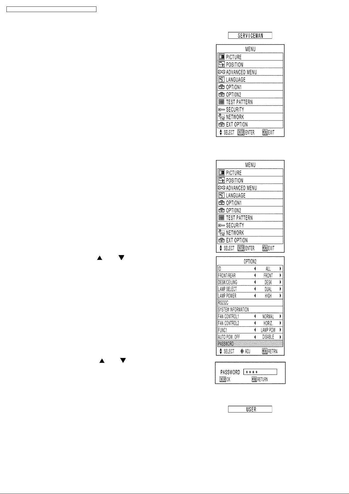
(5) Set the operation mode selector (Computer/Numeric, Projector) switch
to “Projector” on the remote control unit and press the ENTER button.
(6) Press the MENU button.
Note:
· "SERVICEMAN" will appear.
4.2. Resetting to User Mode
(1) Press the MENU button.
The MENU screen will appear.
(2) Select “OPTION2” using the or buttons and press the
ENTER button.
The OPTION2 screen will appear.
(3) Select PASSWORD using the or buttons and press the
ENTER button.
The PASSWORD screen will appear.
(4) Set the operation mode selector (Computer/Numeric, Projector) switch
to "Computer/Numeric" on the remote control unit and input the
password "0000".
Note:
· Asterisk (*) will appear for the password numbers.
(5) Set the operation mode selector (Computer/Numeric, Projector) switch
to "Projector" on the remote control unit and press the ENTER button.
(6) Press the MENU button.
Note:
· "USER" will appear.
8

PT-D5500U / PT-D5500E / PT-D5500UL / PT-D5500EL
4.3. Functions in Serviceman Mode
4.3.1. EXT OPTION
"EXT OPTION" is added to the MENU.
1. CUT OFF
Sets the display ON/OFF for each color (R, G, B).
2. LAMP RELAY
"OFF", "4h", "5h", "6h" . . . "10h", "11h", "12h":
If "SINGLE" is set on LAMP SELECT, Lamp Unit 1 and Lamp Unit 2 are automatically switched alternately at intervals of the
selected setting time (for 4-12 hours).
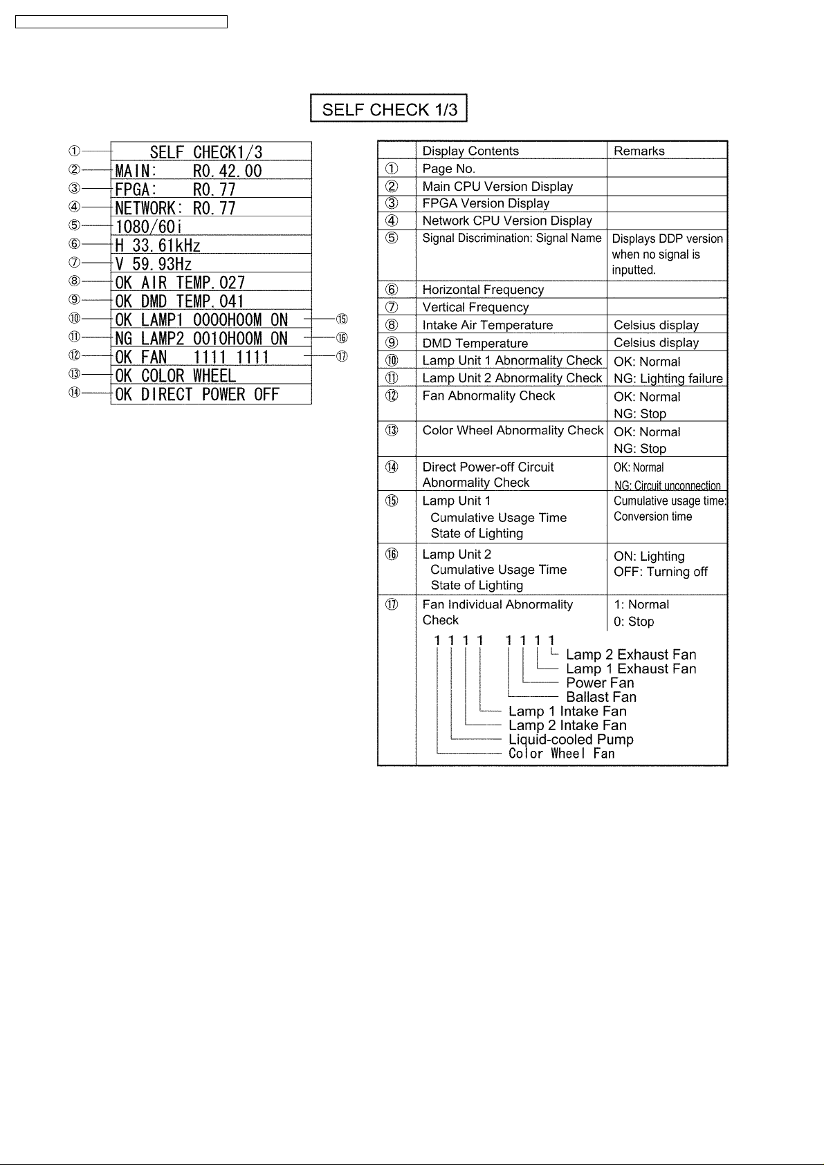
3. SELF CHECK
Displays SELF CHECK.
There are 3 pages, and it is switched with
and buttons.
9
PT-D5500U / PT-D5500E / PT-D5500UL / PT-D5500EL
[1st page]
10
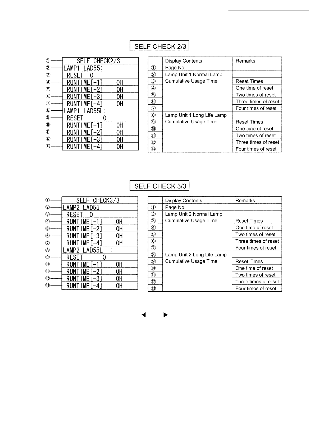
[2nd page]
PT-D5500U / PT-D5500E / PT-D5500UL / PT-D5500EL
[3rd page]
4. CW INDEX
When the color wheel is replaced, adjusts it with
and buttons.
a. Decrease CW INDEX setting value from the default value (289) by 50, and set it to 239.
A blue-purple color mixture appears in the upper right or the upper of the screen. (When CEILING setting, appears it in the
lower left or the lower of the screen.)
b. Increase CW INDEX setting value by 1, and record the value where the color mixture disappears. (The recorded value is
assumed to "A".)
c. Increase CW INDEX setting value from the default value (289) by 50, and set it to 339.
A yellow-green color mixture appears in the lower right or the lower of the screen. (When CEILING setting, appears it in the
upper left or the upper of the screen.)
d. Decrease CW INDEX setting value by 1, and record the value where the color mixture disappears. (The recorded value is
assumed to "B".)
e. Set the mean value (omission below decimal point) of "A" and "B" to the CW INDEX setting value.
11
PT-D5500U / PT-D5500E / PT-D5500UL / PT-D5500EL
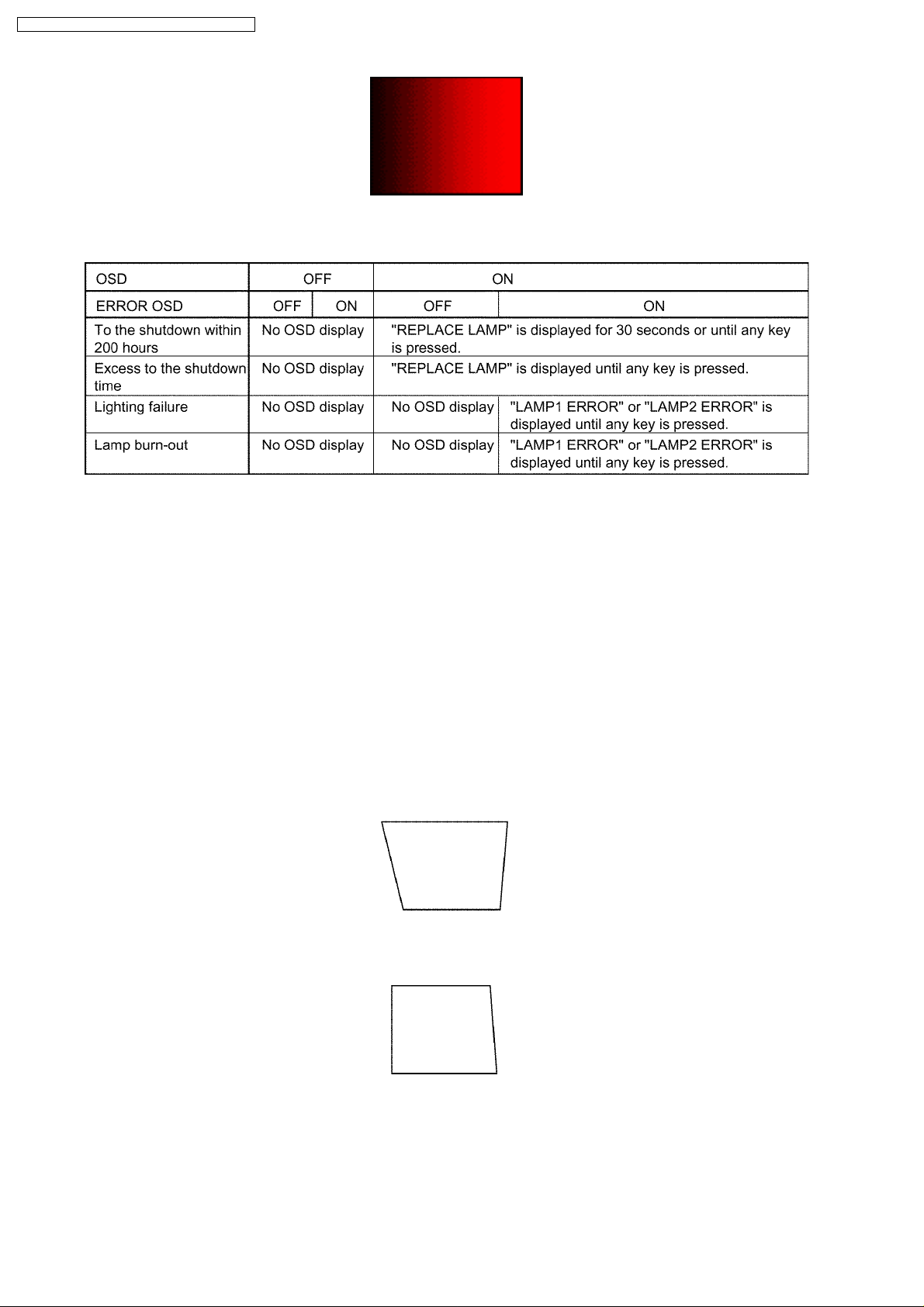
5. ERROR OSD
Displays the lamp status with OSD when you do not see the status LED lights because the rear projection, etc.
6. H.MASK PULSE
When the signal of 480i or 576i is inputted, the synchronization might become unstable. It might be stable when H.MASK
PULSE is set to "SPECIAL".
· STANDARD: Does not execute special signal processing.
· SPECIAL: Executes special signal processing.
7. DIGITAL CINEMA REALITY
When VIDEO, S-VIDEO or 480i signal is inputted, can improve the vertical resolution further.
· OFF: Does not execute DIGITAL CINEMA REALITY processing.
· ON: Detects the signal automatically, and executes DIGITAL CINEMA REALITY processing.
4.3.2. SUB-KEYSTONE
"SUB-KEYSTONE" is added to KEYSTONE in the "POSITION" menu.
If KEYSTONE and "Lens shift" are used at the same time, the right and left may be corrected in the unbalance.
At this time, only the right side can be corrected by SUB-KEYSTONE.
1. The left side is adjusted straight by KEYSTONE.
2. The right side is adjusted straight by SUB-KEYSTONE.
12
PT-D5500U / PT-D5500E / PT-D5500UL / PT-D5500EL
Note:
· SUB-KEYSTONE is a supplementary adjustment function and there is no guaranty of completely functioning. Use it
within the range where the trouble such as deforming the shape of the image does not occur.
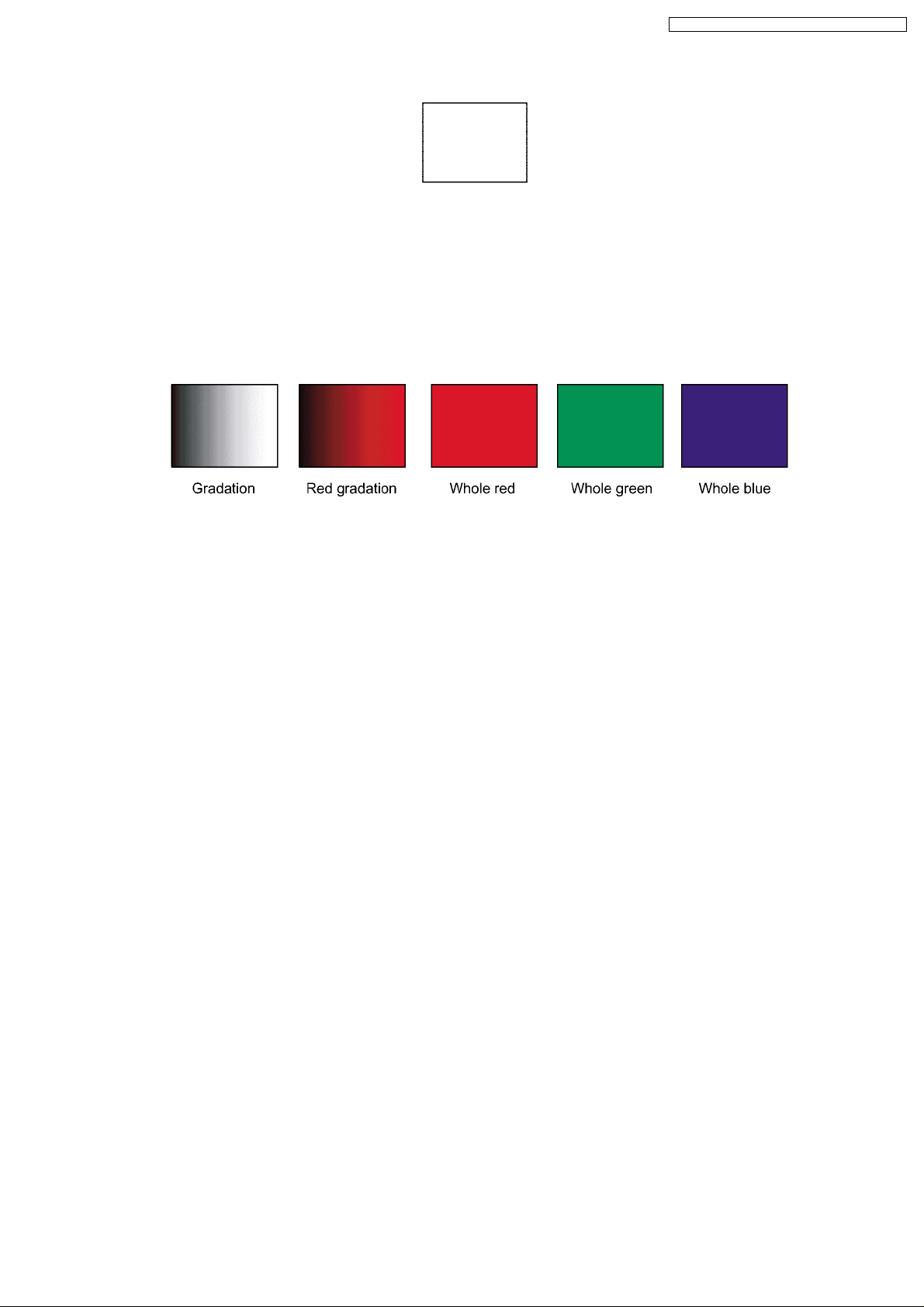
4.3.3. Test Pattern Addition
"Gradation", "Red gradation", "Whole red", "Whole green" and "Whole blue" patterns are added to the test pattern.
"Red gradation" is used for CW INDEX adjustment.
13
PT-D5500U / PT-D5500E / PT-D5500UL / PT-D5500EL
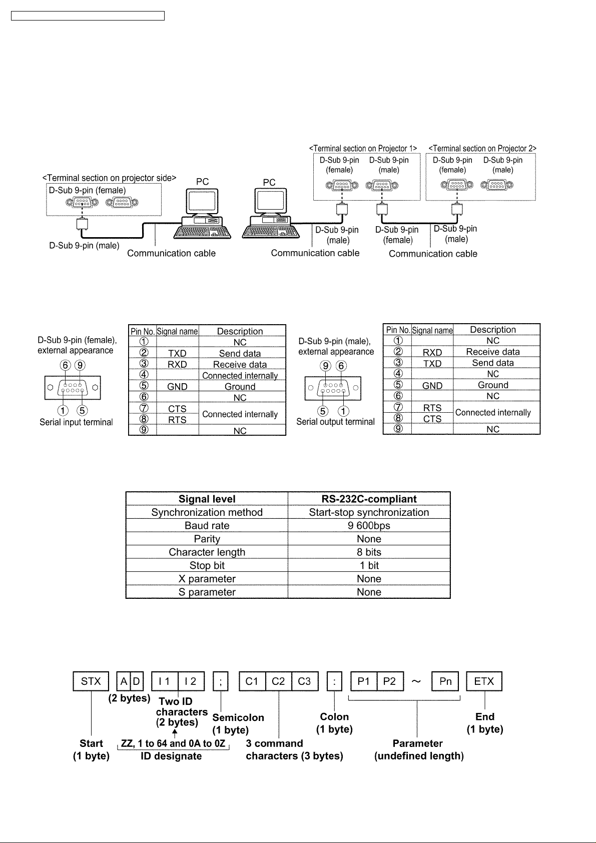
5 Using the Serial Terminals
SERIAL terminals which are on the side-mounted connection terminals conform to RS-232C standard. This projector can be
controlled by a PC which is connected as shown below. Also SERIAL OUT terminal is provided to enable plural projector control.
5.1. Examples of Connection
5.2. Pin Assignments and Signal Names
5.3. Communication Conditions (Factory Setting)
5.4. Basic Format
Transmission from the computer begins with STX, then the ID, command, parameter, and ETX are sent in this order. Add
parameters according to the details of control.
14
PT-D5500U / PT-D5500E / PT-D5500UL / PT-D5500EL
Attention
· No command can be sent or received for 10 to 60 seconds after the lamp starts lighting. Try sending any command after
that period has elapsed.
· When sending several commands, be sure to wait for a response from the projector before sending the next command.
When sending commands without parameters, a colon (:) is not necessary.
Note
· If a wrong command parameter is sent, the projector will send an "ER401" or "ER402" command to the computer.
· A projector ID supported on the RS-232C interface is ZZ (ALL) and a group of 1 to 64 and 0A to 0Z.
· If a command is sent with a projector ID specified, the projector will respond to the computer only in the following cases:
If it coincides with the projector ID,
ID specification is ALL and VPS-SYSTEM is the master, or
ID specification is group and Group is the master.
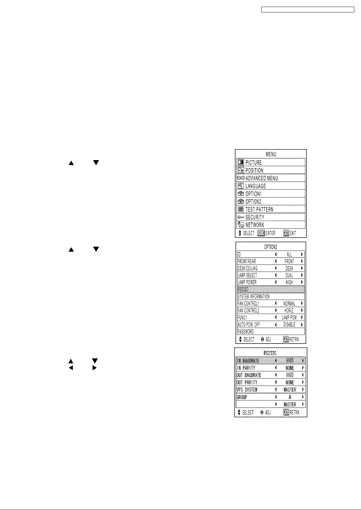
5.5. Procedure of Communication Condition Settings
(1) Press the MENU button.
The MAIN MENU screen will be displayed.
(2) Press the and buttons to select “OPTION2”.
(3) Press the ENTER button.
(4) Press the and buttons to select “RS232C”.
(5) Press the ENTER button.
The RS232C screen will be displayed.
(6) Press the and buttons to select communication conditions.
(7) Press the and buttons to confirm the setting..
(8) Press the MENU button three times.
The on-screen indications disappear, and the system returns to the
normal screen.
15
PT-D5500U / PT-D5500E / PT-D5500UL / PT-D5500EL
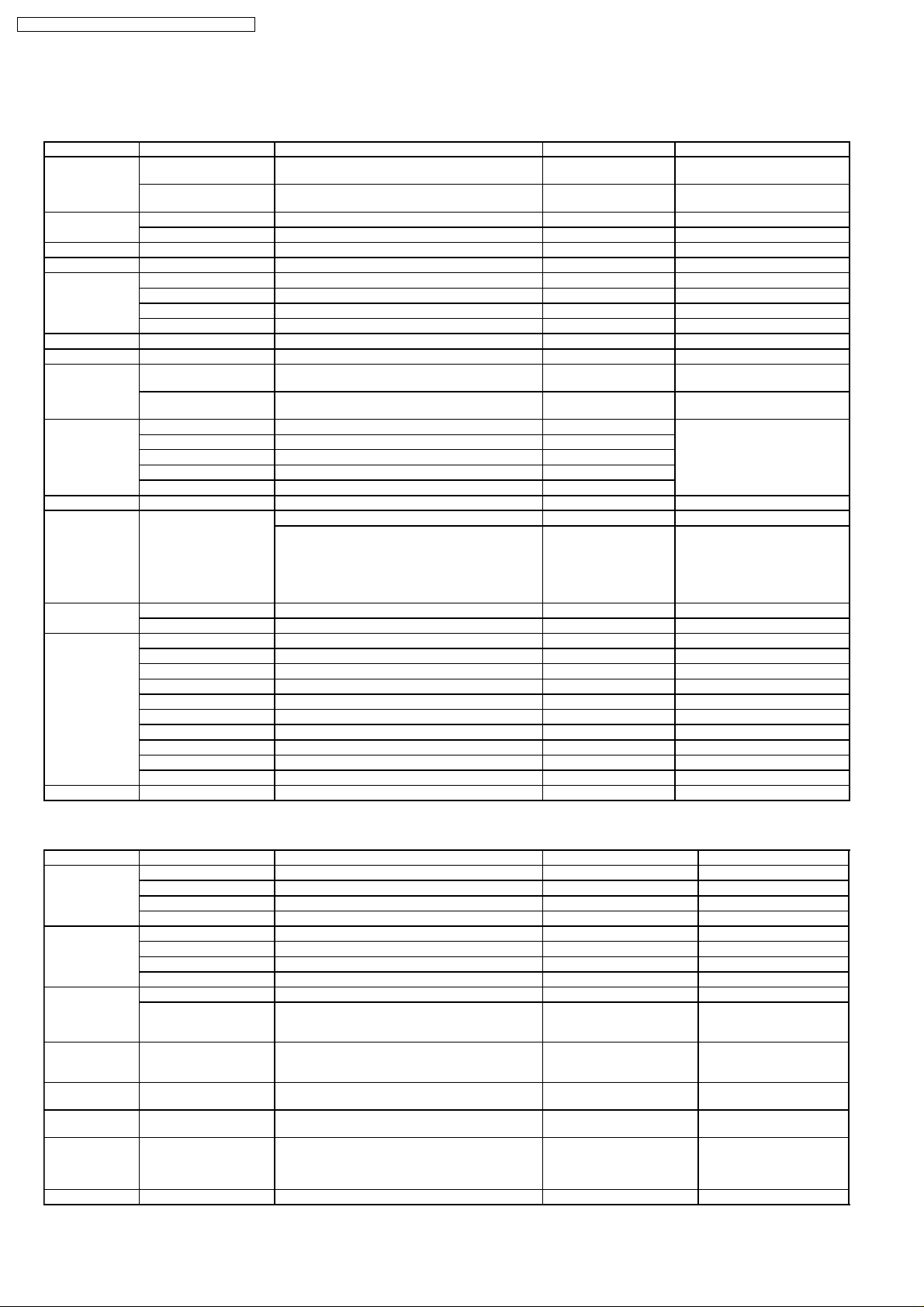
5.6. Control commands
5.6.1. Input Commands
Items Commands:Parameters Functions Callback Remarks
POWER PON POWER ON PON Calls back PON even if
POF STAND-BY POF Calls back PON even if
FREEZE OFZ:0 FREEZE key OFZ:0
MENU OMN MENU key OMN
ENTER OEN ENTER key OEN
CURSOR OCU UP key OCU
STANDARD OST STANDARD key OST
AUTO SETUP OAS AUTO SETUP execution OAS
SHUTTER OSH:0 SHUTTER key OSH:0 Calls back ER402 when
INPUT SELECT IIS:RG1 RGB1 IIS:RG1 Calls back ER402 if the
FUNCTION1 FC1 FUNCTION execution FC1
TEST OTS:p1p2 Test pattern selection OTS:p1p2
ON SCREEN OOS:0 OSD selection OOS:0
NUMBER KEY ONK:0 NUMBER key 0 ONK:0
SYSTEM SEL OSL SYSTEM SELECTER key OSL
OFZ:1 0=OFF 1=ON OFZ:1
OCD DOWN key OCD
OCL LEFT key OCL
OCR RIGHT key OCR
OSH:1 0=OFF 1=ON OSH:1 Calls back ER402 when
IIS:RG2 RGB2 IIS:RG2
IIS:VID VIDEO IIS:VID
IIS:SVD S-VIDEO IIS:SVD
IIS:DVI DVI IIS:DVI
00=OFF 01=Whole white 02=Whole black
03=Flag 05=1% window 06=1% window
inversion 07=Focus 08=Colorbar
09=Gradation 10=16:9 22=Whole red
23=Whole green 24=Whole blue 41=Red
gradation
OOS:1 0= OSD OFF 1=OSD ON OOS:1
ONK:1 NUMBER key 1 ONK:1
ONK:2 NUMBER key 2 ONK:2
ONK:3 NUMBER key 3 ONK:3
ONK:4 NUMBER key 4 ONK:4
ONK:5 NUMBER key 5 ONK:5
ONK:6 NUMBER key 6 ONK:6
ONK:7 NUMBER key 7 ONK:7
ONK:8 NUMBER key 8 ONK:8
ONK:9 NUMBER key 9 ONK:9
REMOTE2 is effective.
REMOTE2 is effective.
SHUTTER of REMOTE2 is ON.
SHUTTER of REMOTE2 is OFF.
input switch of REMOTE2 is
available.
5.6.2. Data setting Commands
Items Commands:Parameters Functions Callback Remarks
INSTALLATION OIL:0 Front/Floor OIL:0
LAMP SELECT LPM:0 Lamp selection LPM:0 *1
LAMP POWER OLP:0 LAMP POWER setting OLP:0
USER MEMORY OCS:p1p2 USER MEMORY switching OCS:p1p2 p1p2:00,01,02,03 Sets
ENTRY USER
MEMORY
DELETE USER
MEMORY
SET DATE TSD:y1y2y3y4
SET TIME TST:h1h2m1m2s1s2 Time setting TST:h1h2m1m2s1s2 *3
OIL:1 Rear/Floor OIL:1
OIL:2 Front/Ceiling OIL:2
OIL:3 Rear/Ceiling OIL:3
LPM:1 0=DUAL 1=SINGLE LPM:1
LPM:2 2=LAMP1 3=LAMP2 LPM:2
LPM:3 LPM:3
OLP:1 0=HIGH 1=LOW OLP:1 Calls back ER402 when
OES Enters current receiving signal in the
ODS:p1p2 Deletes data in the specified user
m1m2d1d2w
user memory.
memory.
Date setting TSD:y1y2y3y4m1m2d1d2w y1y2y3y4m1m2d1d2 + a
OES:p1p2
ODS:p1p2 p1p2:01,02,03 *2
using a long life
lamp.
00 when the user
memory is not used. *2
day of the week
(Mon.=1 Tues.=2 --Sun.=7) *3
16

PT-D5500U / PT-D5500E / PT-D5500UL / PT-D5500EL
*1 In the SINGLE mode, one of lamp 1 and lamp 2 whose remainder time is longer is turned ON.
*2 The input of p1p2 accepts any of the types +1, +01, 1 and 01.
*3 Displays of SET DATE and SET TIME are set by UTC (Coordinated Universal Time).
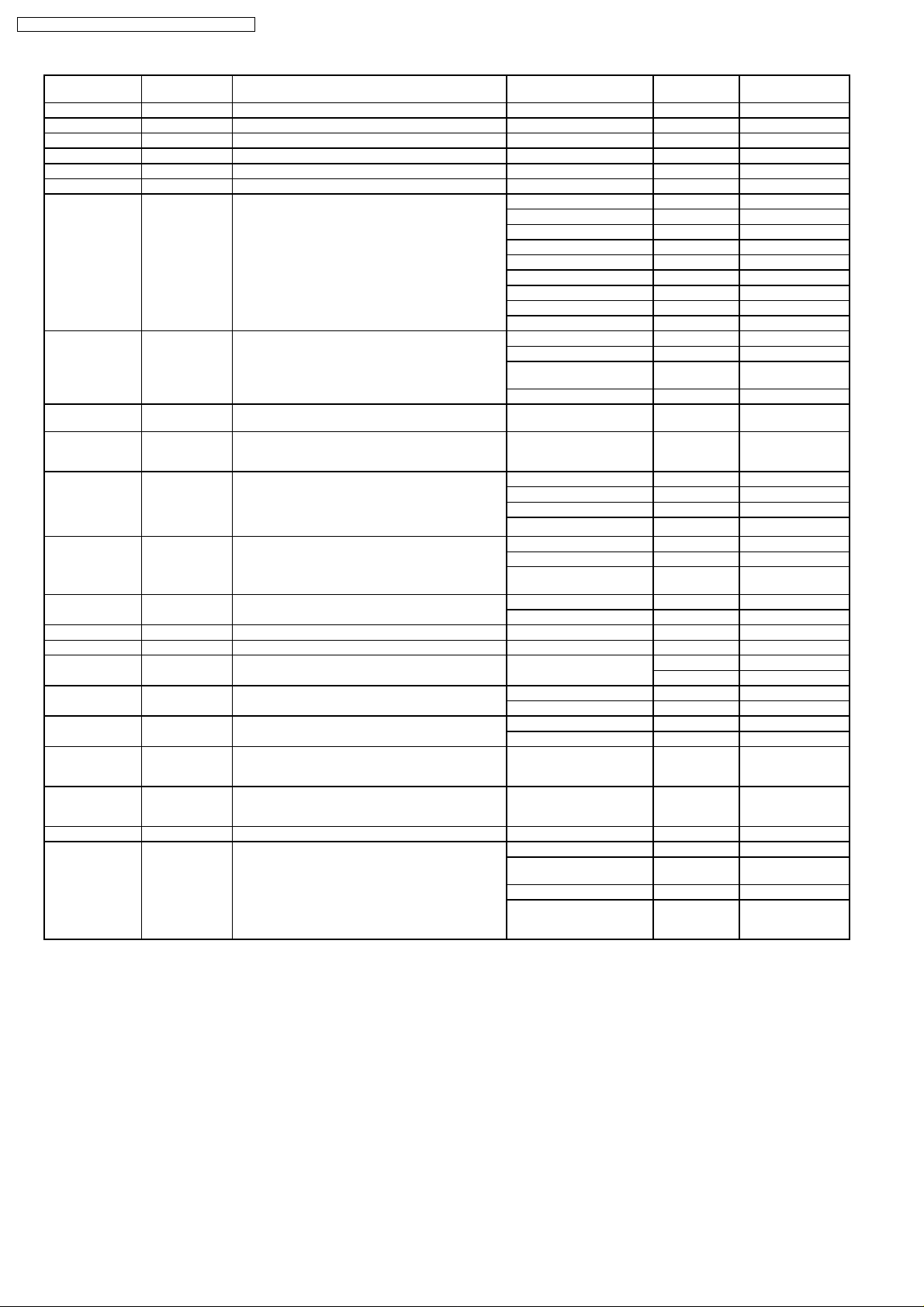
5.6.3. Inquiry Commands
Items Commands:Para
POWER
CONDITION
FREEZE QFZ Inquiry about FREEZE 0 OFF
SHUTTER QSH Inquiry about SHUTTER 0 OFF
INPUT SIGNAL QIN Inquiry about INPUT SIGNAL RG1 RGB1
TEST QTS Inquiry about test pattern p1p2
ON SCREEN QOS Inquiry about OSD 0 off
PICTURE MODE QPM Inquiry about PICTURE MODE NAT NATURAL
COLOR QVC Inquiry about COLOR p1p2p3
TINT QVT Inquiry about TINT p1p2p3
COLOR TEMP. QTE Inquiry about COLOR TEMP. 1 MIDDLE
WHITE BALANCE
LOW(R)
WHITE BALANCE
LOW(G)
WHITE BALANCE
LOW(B)
WHITE BALANCE
HI(R)
WHITE BALANCE
HI(G)
WHITE BALANCE
HI(B)
CONTRAST QVR Inquiry about CONTARST p1p2p3
BRIGHTNESS QVB Inquiry about BRIGHTNESS p1p2p3
SHARPNESS QVS Inquiry about SHARPNESS p1p2p3
NOISE
REDUCTION
AI QAI Inquiry about AI settings 0 OFF
TV-SYSTEM QSG Inquiry about TV-SYSTEM AT1 AUTO1
SHIFT H QTH Inquiry about horizontal shift p1p2p3p4
SHIFT V QTV Inquiry about vertical shift p1p2p3p4
SIZE QSE Inquiry about SIZE 0 AUTO
ZOOM(H) QZH Inquiry about ZOOM (H) p1p2p3
ZOOM(V) QZV Inquiry about ZOOM (V) p1p2p3
CLOCK PHASE QCP Inquiry about CLOCK PHASE p1p2p3
TOTAL DOTS QTD Total dots p1p2p3p4
meters
QPW Inquiry about POWER CONDITION 000 OFF Available in
QOR Inquiry about WHITE BALANCE LOW (R) p1p2p3
QOG Inquiry about WHITE BALANCE LOW (G) p1p2p3
QOB Inquiry about WHITE BALANCE LOW (B) p1p2p3
QHR Inquiry about WHITE BALANCE HIGH (R) p1p2p3
QHG Inquiry about WHITE BALANCE HIGH (G) p1p2p3
QHB Inquiry about WHITE BALANCE HIGH (B) p1p2p3
QNS Inquiry about NR 0 OFF
Functions Callback Interpretati
001 ON
1 ON
1 ON
RG2 RGB2
VID VIDEO
SVD S-VIDEO
AUX AUX
1 on
STD STANDARD
DYN DYNAMIC
CIN CINEMA
GRA GRAPHIC
2 HIGH
4 USER
10 DEFAULT
1 ON
1 ON
AT2 AUTO2
NTS NTSC
N44 NTSC4.43
PAL PAL
PAN N-PAL
PAM M-PAL
SEC SECAM
P60 PAL60
BW5 Black and
BW6 Black and
1 4:3
2 16:9
3 S4:3
white 50
white 60
on
Remarks
STANDBY
17
PT-D5500U / PT-D5500E / PT-D5500UL / PT-D5500EL
Items Commands:Para
DISPLAY DOTS QDD Display dots p1p2p3p4
TOTAL LINES QTL Total lines p1p2p3p4
DISPLAY LINES QDL Display lines p1p2p3p4
CLAMP POSITION QLT Inquiry about ClAMP POSITION p1p2p3
KEYSTONE QKS Inquiry about KEYSTONE p1p2p3
LINEARITY QLI Inquiry about LINEARITY p1p2p3
LANGUAGE QLG Inquiry about LANGUAGE ENG English
INSTALLATION QSP Inquiry about INSTALLATION 0 Front/Floor
SET RUNTIME QST Inquiry about projector runtime p1p2p3p4p5 00000h -
LAMP ON TIME
(LAMP TIMER)
LAMP SELECT QSL Inquiry about LAMP SELECT
LAMP POWER QLP Inquiry about LAMP POWER 0 HIGH(300 W)
VPS SYSTEM QVY Inquiry about VPS SYSTEM 0 SLAVE
GROUP GET ADa1a2;QRG Inquiry about GROUP information ADa1a2;RGSg1g2
MASTER GET ADg1g2;QRL Inquiry about MASTER information ADa1a2;RLSa1a2
TEMP QTM:p1 Inquiry about TEMP p1p2p3p4/p5p6p7p8
FAN CONTROL QFM Inquiry about FAN CONTROL 0 NORMAL
FUNCTION1 QFC Inquiry about FUNCTION1 1 LAMP POWER
USER MEMORY QSB Inquiry about USER MEMORY p1p2 p1p2 : 01,02,03
GET DATE QGD Inquiry about the system date y1y2y3y4m1m2d1d2w yyyymmdd (a
GET TIME QGT Inquiry about the system time h1h2m1m2s1s2 hhmmss UTC
GET SYSTEM
STATUS
meters
Q$L:p1
(p1=1or2)
Q$S Inquiry about the lamp status 0 Lamp off
Inquiry about LAMP ON TIME (1=LAMP1,
2=LAMP2) Conversion time for HIGH of
recognized lamp
Calls back the set content.
(Even if the callback is DUAL, it does
not necessarily light without fail with
both lamps.)
Functions Callback Interpretati
DEU German
FRA French
ESP Spanish
ITL Italian
JPN Japanese
CHI Chinese
RUS Russian
KOR Korean
1 Rear/Floor
2 Front/Ceilin
3 Rear/Ceiling
p1p2p3p4 0000h -
0 DUAL
1 SINGLE
2 LAMP1
3 LAMP2
1 LOW(240 W)
2 Long life
1 MASTER
(Celsius/Fahrenheit)
1 HIGHLAND
2 SIZE
1 In turning
2 Lamp on
3 In turning
on
g
99999h
9999h
lamp (160 W)
p1=0 intake
p1=2 DMD
day of the
week)
on
off
(cooling)
Remarks
(ER401 when it
is not used)
Day of the week:
Mon.=1, Tues.=2,
. . . Sun.=7
18
PT-D5500U / PT-D5500E / PT-D5500UL / PT-D5500EL
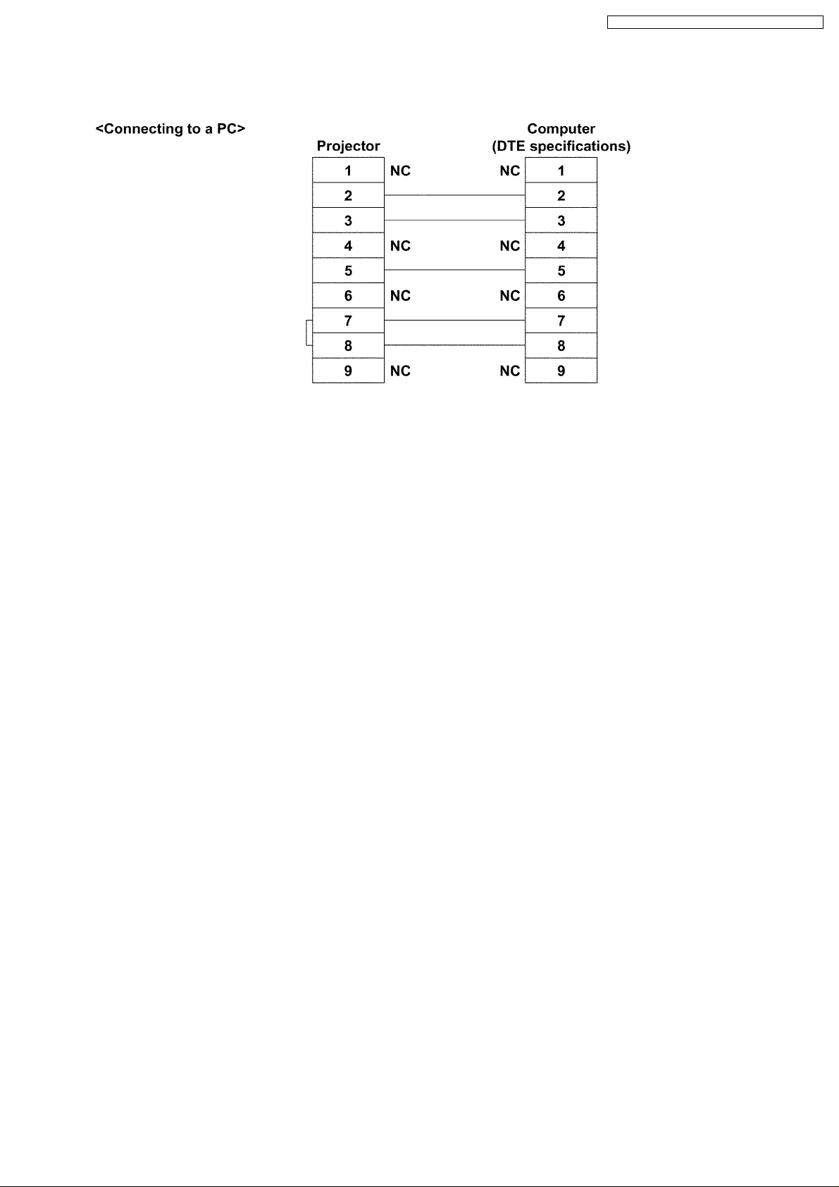
5.7. Cable specifications
Note
To connect the computer to the SERIAL terminal, prepare an adequate communication cable that fits to your personal
computer.
19
PT-D5500U / PT-D5500E / PT-D5500UL / PT-D5500EL
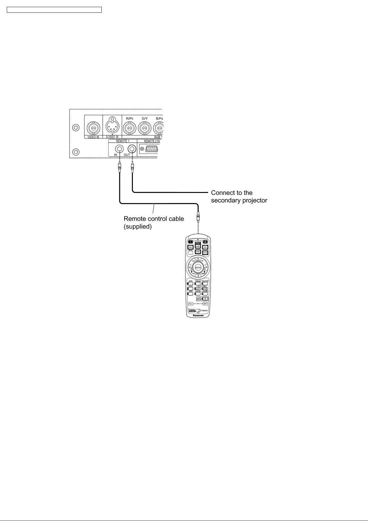
6 Using a Wired Remote Control
6.1. Connection Example
When two or more projectors are connected in the system, connect the projectors with the supplied remote control cable to
simultaneously control the projectors with a remote control unit through the REMOTE1 IN/OUT terminal. It is effective to use the
wired remote control in the environment in which an obstacle stands in the light path or where the system is susceptible to outside
light.
6.2. Setting the Projector ID Number for Remote Control
Every projector has its ID number and the ID number of the controlling projector must be set to the remote control in advance so
that the user can operate the remote control. The ID number of the projector is set to “ALL” on shipping, and use the ID ALL button
of the remote control when using only a single projector.
Procedure of ID setting
1. Change the position of the operation mode selector awitch to “Computer”.
2. Press the ID SET button, and within five seconds use the number (0 to 9) buttons to enter the 2-digit ID number set by the
projector.
3. Change the position of the operation mode selector switch to “Projector”.
However, if the ID ALL button is pressed, the projector can be controlled regardless of the ID number of the projector
(simultaneous control mode).
· Do not press the ID SET button accidentally or carelessly because the ID number on the remote control can be set even
when no projector is around.
If the ID SET button is pressed, the ID number goes back to the one set before pressing the ID SET button unless a
numeric button is pressed within five seconds after the ID SET button is pressed.
· Your specified ID number is stored in the remote control unit unless another one is specified later. However, the stored
ID will be erased if the batteries of the remote control are left exhausted. When the dry cells are replaced, set the same
ID number again.
20

PT-D5500U / PT-D5500E / PT-D5500UL / PT-D5500EL
7 Support for Service
7.1. Supporting Methods
We will support according to the following methods.
Supporting methods Applied parts
Replaced by module or block FM-Module (For specified components, supplies them discretely.)
Ballast module
Power module
Replaced by discrete components Other components
Replacd at the manufacturing
department
7.2. Note for Replacement of P.C.Boards
7.2.1. When replacing the A-P.C.Board
· Transfer the data of the original A-P.C.Board to the new A-P.C.Board using the adjustment software and a personal computer.
(If you cannot transfer the data, remove IC2508 and IC2509 from the original board and mount them on the new board.)
* For the adjustment software, consult an authorized service center.
7.3. Replacement of the lithium battery on the A-P.C.Board
Optical block unit (including DMD™ block) , DMD™ drive module, Assembly
parts
If the lithium battery will be empty, replace it with a new one (CR2032 or equivalent).
Cautions
· Explosion may occur if replacing the battery with an incorrect one.
· Dispose of used batteries according to the instructions.
8 Cautions for Service
8.1. Servicing Methods
· Never unplug the power cord from the outlet, open the circuit breaker, or perform other procedures to cut off the power line
during the operation of any cooling fan.
· Be sure to unplug the power cord from the power outlet before servicing.
Powering off the projector
1. Press the POWER OFF "
2. Select "Execute" with
The projection of the image stops, and POWER indicator of the main unit lights up orange. (Cooling fans keep running.)
3. Wait until the POWER indicator turns to red (i.e., until the cooling fans stop).
4. Press the "
" marked side of the MAIN POWER switch to turn off the projector.
" button.
or button and press the ENTER button.(or press the POWER OFF " " button again.)
21
PT-D5500U / PT-D5500E / PT-D5500UL / PT-D5500EL
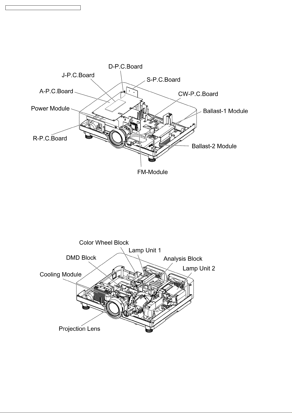
9 Parts Location
9.1. Electrical Parts Location
9.2. Electromechanical Parts Location
22
PT-D5500U / PT-D5500E / PT-D5500UL / PT-D5500EL
10 Replacement of Lamp Unit
Cautions
· Wait until the lamp is cooled sufficiently before replacing the lamp unit.
10.1. Precautions on Lamp Unit Replacement
· Be careful when handling a light source lamp . The lamp may burst if it hit by solid objects or if it is dropped because of high
air pressure inside the bulb.
· A used lamp unit may burst if it is handled violently.
For disposition of used lamps, request an industrial waste disposal contractor.
· Do not reset the cumulative time, except when the lamp unit has been replaced with a new unit.
· If you continue to use a lamp after the replacement time, the lamp may break.
· Philips screwdriver is necessary when replacing a lamp unit.
Take care not to slip your hand when using a screwdriver.
· A lamp unit is an optional part. Contact the dealer.
Replacement lamp unit model No.: ET-LAD55 (single bulb), ET-LAD55W (double bulbs)
Rating: 300 W
Long-life lamp unit model No.: ET-LAD55L (single bulb), ET-LAD55LW (double bulbs)
Rating: 160 W
· Other lamps than specified above cannot be used. Be sure to use the specified lamp.
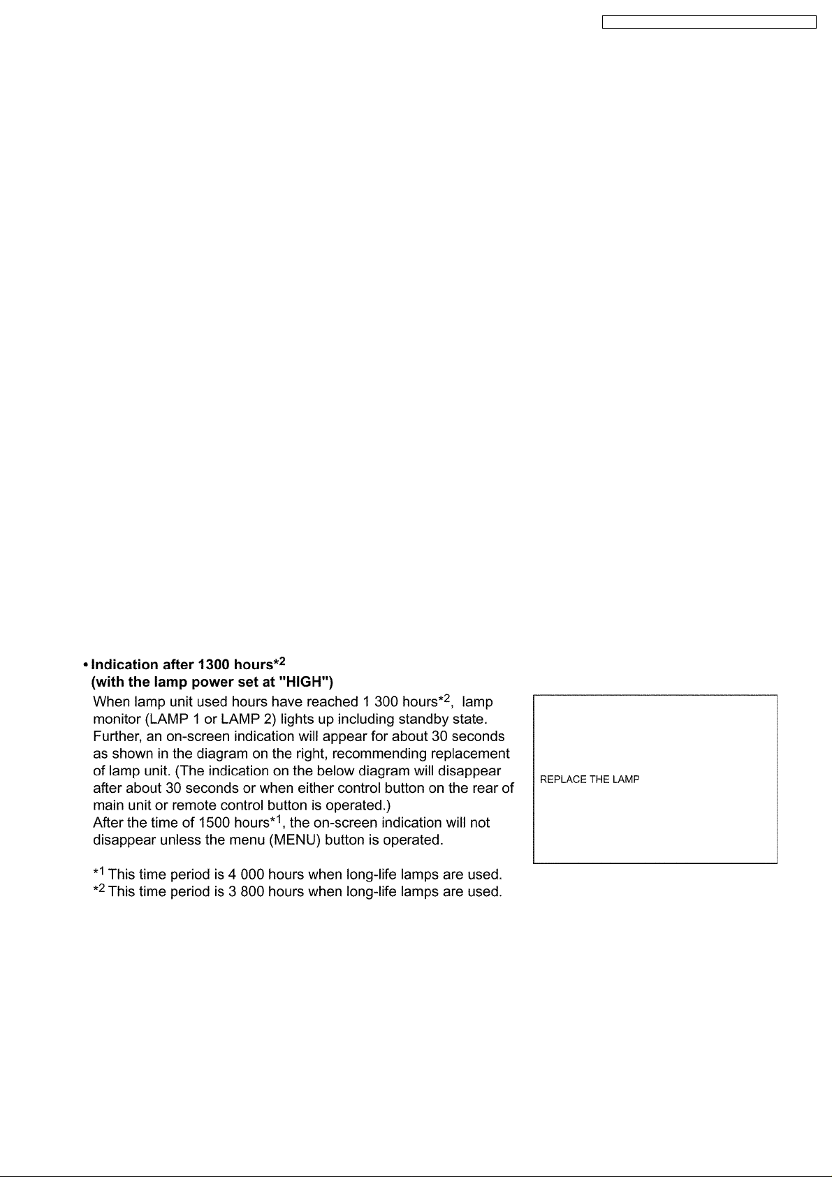
10.2. Timing of Lamp Unit Replacement
The lamp used for the light source has its due life. The life of light source lamp used in the main unit is 1 500 hours*1(when lamp
power is HIGH and lamp selection is DUAL). However, it may happen that the lamp becomes dead (will not light) by the time of 1
500 hours
the times of lighting and the intervals between previous lighting and next lighting). Therefore, it is strongly recommended for the
user to keep a spare bulb. If your lamp unit is not replaced after 1 300 hours
will be turned off automatically at the time of 1 500 hours
minutes later, entering a standby state even if it is turned on again.
*1
depending on the characteristics of individual lamps and working conditions (lamps may reduce their life affected by
*2
*1
of initial lighting, power supply is turned off automatically about 10
(with the lamp power set at “HIGH”), power supply
23
PT-D5500U / PT-D5500E / PT-D5500UL / PT-D5500EL
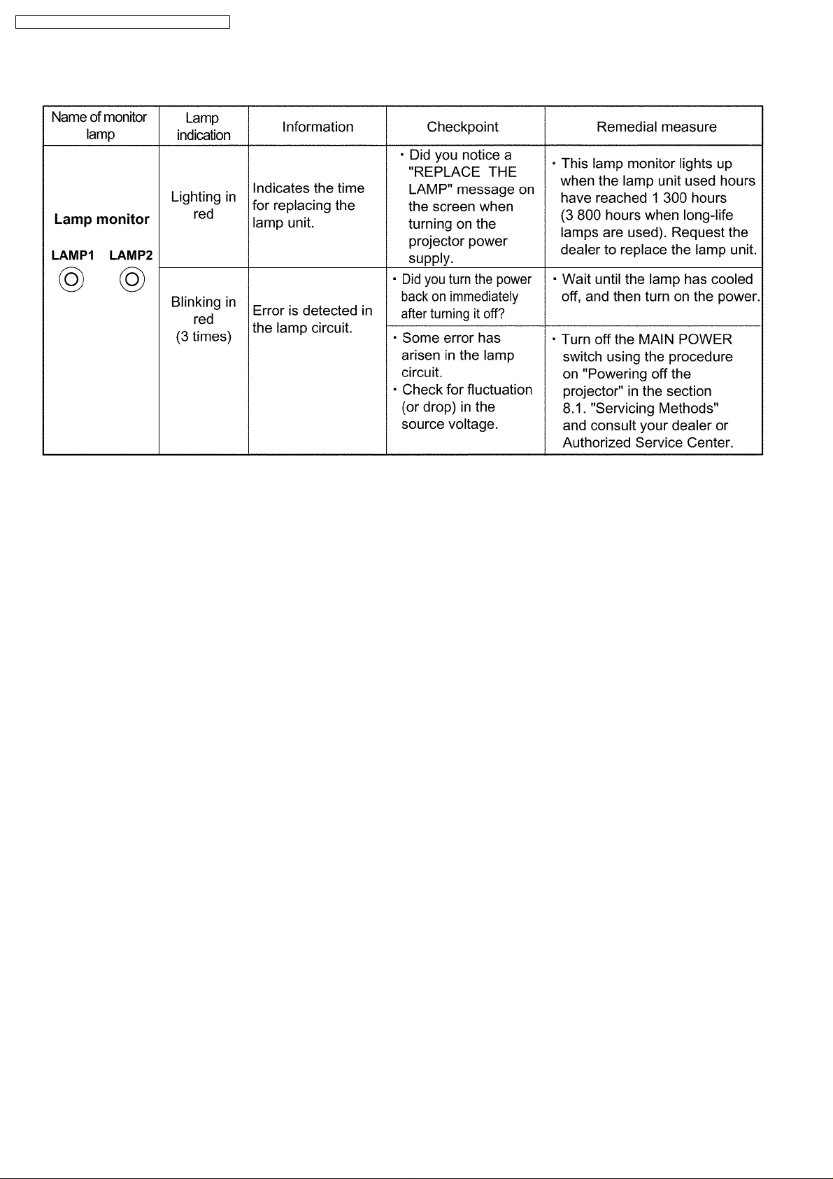
10.3. Indication of Lamp Monitor
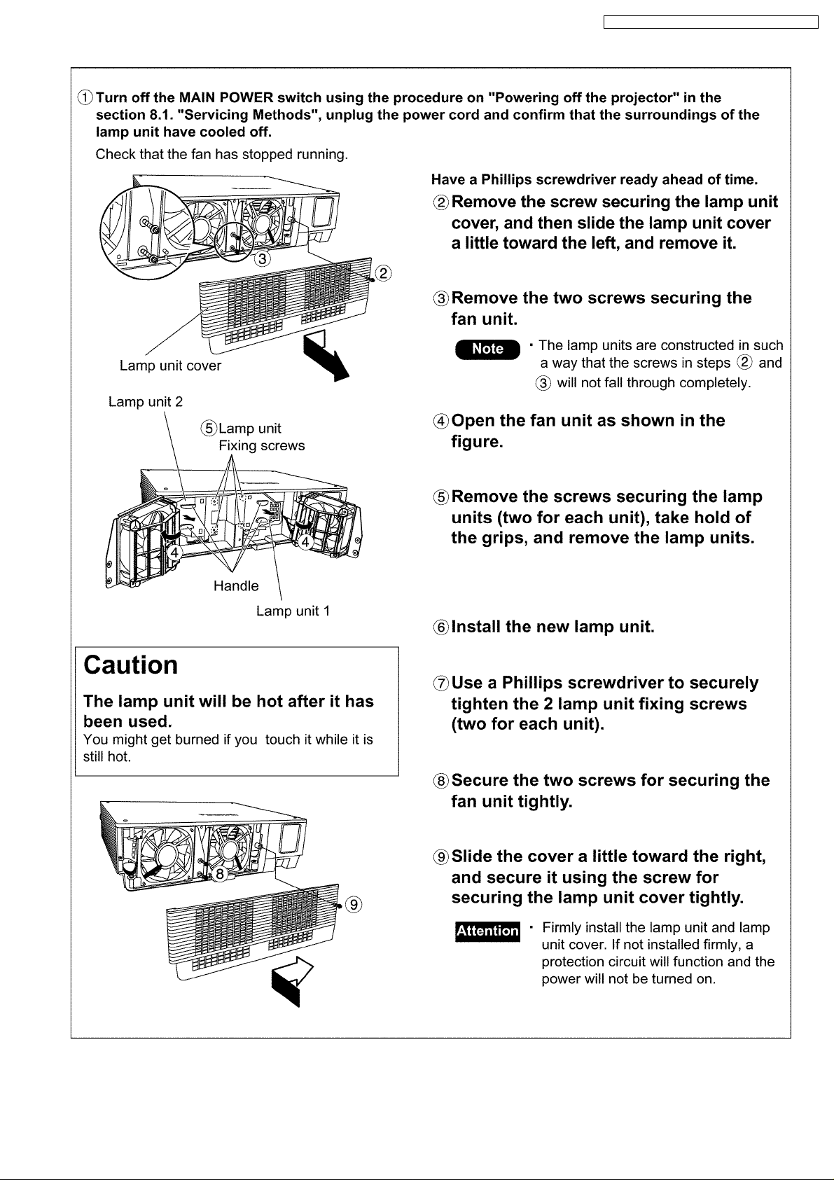
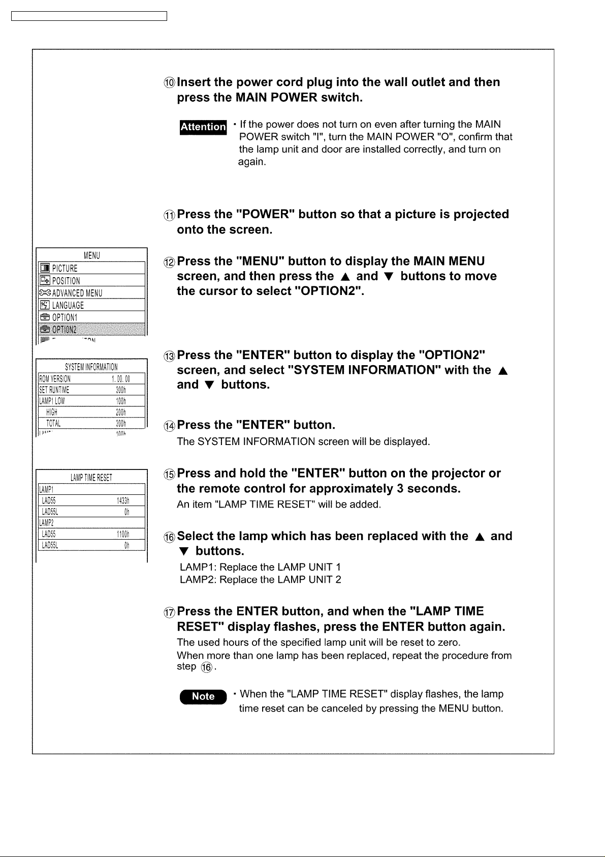
10.4. Procedure of Lamp Unit Replacement
NOTE:
· Be sure to follow steps 11 to 17 in ten minutes after turning on the projector because the projector is turned off in ten
minutes if the RUNTIME indication is 1 500h or more.
24
PT-D5500U / PT-D5500E / PT-D5500UL / PT-D5500EL
25
PT-D5500U / PT-D5500E / PT-D5500UL / PT-D5500EL
26
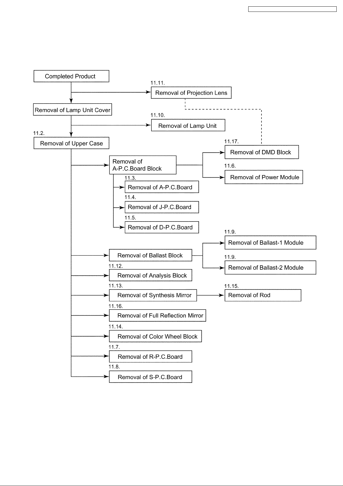
11 Disassembly Instructions
11.1. Flowchart for Disassembly
To assemble, reverse the disassembly procedures.
PT-D5500U / PT-D5500E / PT-D5500UL / PT-D5500EL
27
PT-D5500U / PT-D5500E / PT-D5500UL / PT-D5500EL
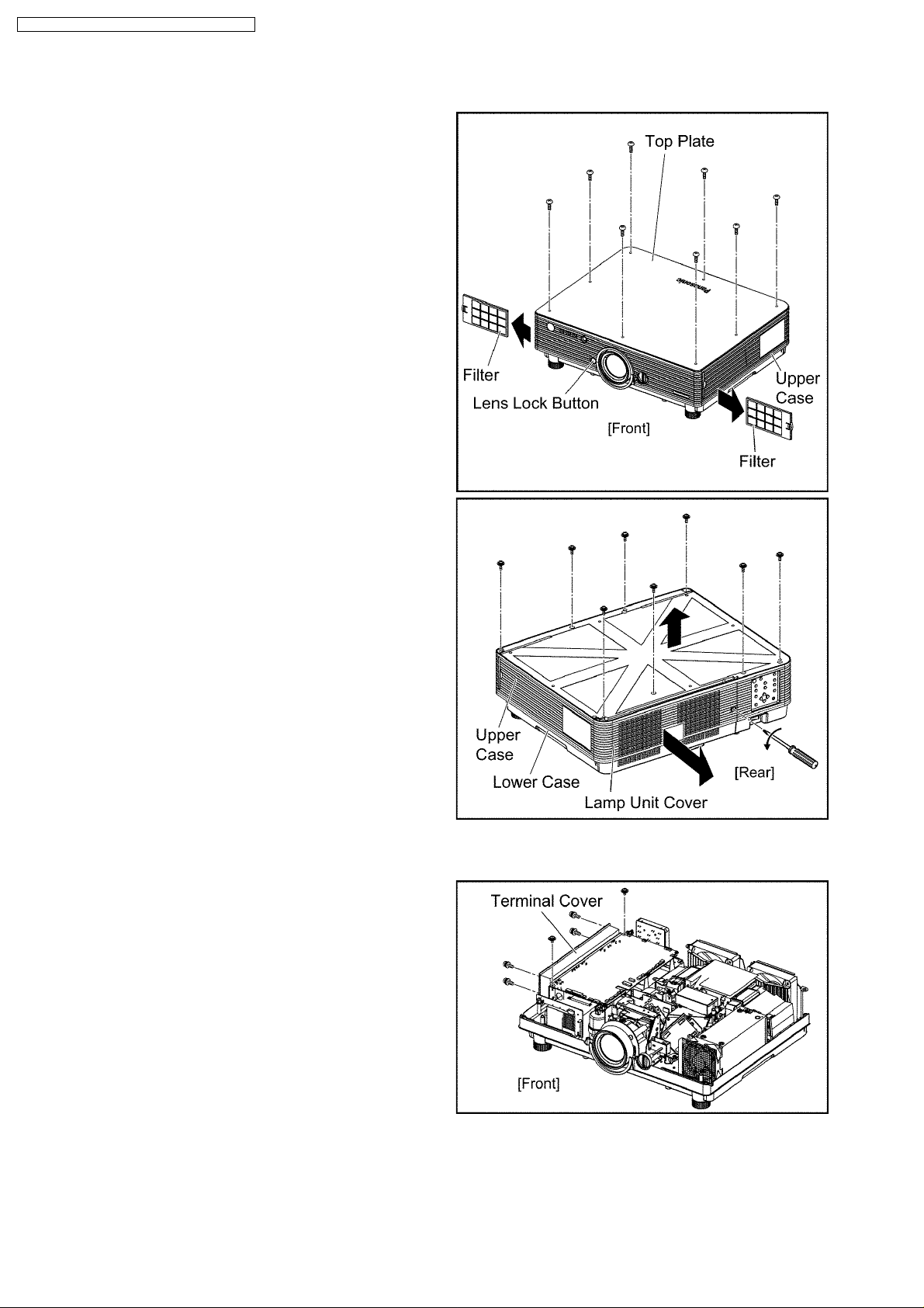
11.2. Removal of Upper Case
(1) Unscrew the 8 screws and remove the top plate.
(2) Remove the filters (R, L). (Pull them horizontally out.)
(3) Loosen the 1 screw fixing the lamp unit cover until it idles,
slightly slide the cover horizontally and remove it.
(4) Unscrew the 8 screws and remove the upper case.
Note:
· Confirm the lens lock button actuates correctly when
you reassemble the upper case as it was.
11.3. Removal of A-P.C.Board
(1) Remove the upper case according to the section 11.2. "Removal
of Upper Case".
(2) Unscrew the 6 screws and remove the terminal cover.
28
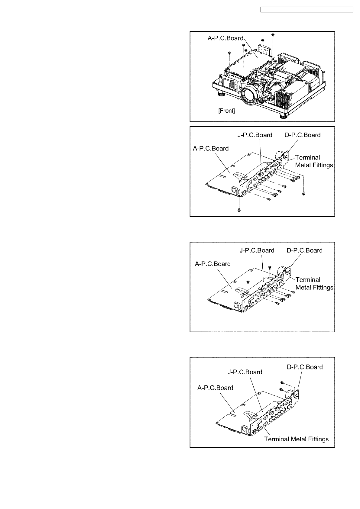
(3) Unscrew the 5 screws and remove the A-P.C.Board block.
(4) Pull out the flexible cable connected to the J-P.C.Board. (The
reverse side of A-P.C.Board)
(5) Unscrew the 10 screws and remove the A-P.C.Board. (The block
of the terminal metal fittings, J-P.C.Board and D-P.C.Board
remains.)
PT-D5500U / PT-D5500E / PT-D5500UL / PT-D5500EL
11.4. Removal of J-P.C.Board
(1) Remove the A-P.C.Board block according to the steps 1 through
3 in the section 11.3. "Removal of A-P.C.Board".
(2) Pull out the flexible cable connected to the A-P.C.Board.
(3) Unscrew the 8 screws and remove the J-P.C.Board.
11.5. Removal of D-P.C.Board
(1) Remove the A-P.C.Board block according to the steps 1 through
3 in the section 11.3. "Removal of A-P.C.Board".
(2) Unscrew the 2 screws and remove the D-P.C.Board.
29
 Loading...