

Page 1
< 1 >
S PEC F ILE
Product Number : PT-D4000
Product Name : DLP
™
Projectors
As of May 2007. Specifications subject to change without notice.
Page 2

S PEC F ILE
PT-D4000
DLP™Projectors
As of May 2007 < 2 >
Specifications
Main Unit
Power supply: North America:
Europe:
Power consumption: North America:
Europe:
DLP™ chip: Panel size:
Display method:
Pixels:
Lens:
Lamp:
Screen size:
Brightness*
1
:
Center-to-corner uniformity*1:
Contrast*1:
Resolution:
Scanning frequency: RGB:
YPBPR (YCBCR):
S-Video/Video:
Optical axis shift:
Keystone correction range:
Installation:
Terminals*2: DVI-D IN:
RGB 1 IN:
R, G, B:
Y, P B, PR:
RGB 2 IN:
R, G, B:
Y, P B, PR:
VIDEO IN:
S-VIDEO IN:
SERIAL IN:
SERIAL OUT:
REMOTE 1 IN:
REMOTE 1 OUT:
REMOTE 2 IN:
LAN:
Power cord length:
Cabinet materials:
On-screen menu:
120 V AC, 50/60 Hz
220–240 V AC, 50/60 Hz
540 W (540 VA) (10 W during standby mode with fan stopped)
520 W (570 VA) (15 W during standby mode with fan stopped)
0.7˝ diagonal (4:3 aspect ratio)
DLP™ chip x 1, DLP™ system
786,432 (1,024 x 768) x 1, total of 786,432 pixels
Powered zoom/focus lenses (4:3 aspect ratio: 1.8 –2.4:1),
F 1.7–2.0, f 25.6–33.8 mm
210 W UHM™ lamps (x 2) (dual lamp system)
50–600 inches (50–200 inches with the ET-DLE050), 4:3 aspect ratio
4,000 lumens (dual lamp, high power mode)
90%
1,600:1 (full on/full off, contrast mode: high, brightness: 2,000 lumens)
800:1 (full on/full off, contrast mode: normal)
1,024 x 768 pixels
(1,600 x 1,200 pixels compatible, compression mode)
Horizontal: 15–91 kHz, Vertical: 50–85 Hz,
Dot clock: 150 MHz or lower
480i: fH 15.75 kHz; fV 59.94 Hz, 576i: fH 15.63 kHz; fV 50 Hz,
480p: fH 31.50 kHz; fV 59.94 Hz, 576p: fH 31.25 kHz; fV 50 Hz,
720/60p: fH 45 kHz; fV 60 Hz, 720/50p: fH 37.5 kHz; fV 50 Hz,
1035/60i: fH 33.75 kHz; fV 60 Hz, 1080/60i: fH 33.75 kHz; fV 60 Hz,
1080/50i: fH 28.13 kHz; fV 50 Hz, 1080/60p: fH 67.5 kHz; fV 60 Hz,
1080/50p: fH 56.25 kHz; fV 50 Hz
Horizontal: 15.75/15.63 kHz, Vertical: 50/60 Hz,
(NTSC, NTSC4.43, PAL, PAL60, PAL-N, PAL-M, SECAM)
Horizontal (manual) and vertical (powered),
Horizontal: ±10%, vertical: +50%
Vertical: ±30°
Ceiling/floor, front/rear
DVI-D 24-pin x 1, DVI 1.0 compliant, HDCP compatible, for single link
only
480p, 576p, 1080/60i, 1080/50i, 1080/60p, 1080/50p, 720/60p,
720/50p, VGA60, SVGA60, XGA50, XGA60, XGA70, XGA75, XGA85,
SXGA50, SXGA60, SXGA+60, WXGA768/50, WXGA768/60
BNC x 5
G: 0.7 Vp-p (G: 1.0 Vp-p for sync on G), 75Ω,
B, R: 0.7 Vp-p, 75Ω
HD/VD, SYNC: TTL (positive/negative)
Y: 1.0 p-p, 75Ω (including sync signal), PB/PR: 0.7 Vp-p, 75Ω
D-sub HD 15-pin x 1
G: 0.7 Vp-p (G: 1.0 Vp-p for sync on G), 75Ω,
B, R: 0.7 Vp-p, 75Ω
HD/VD, SYNC: TTL (positive/negative)
Y: 1.0 p-p, 75Ω (including sync signal), PB,/PR: 0.7 Vp-p, 75Ω
BNC x 1, 1.0 Vp-p, 75Ω
Mini DIN 4-pin x 1, Y: 1.0 Vp-p, C: 0.286 Vp-p, 75Ω
D-sub 9-pin x 1 (RS-232C compliant) for external controller
D-sub 9-pin x 1 (RS-232C compliant) for external controller
M3 jack x 1 for wired remote control or link control
M3 jack x 1 for link control
D-sub 9-pin x 1 for external control (parallel)
RJ-45 x 1, compliant with PJLink™, 10Base-T/100Base-TX
3.0 m (9´10˝)
Molded plastic
9 languages: English, French, German, Spanish, Italian, Russian,
Korean, Chinese, and Japanese
Page 3
S PEC F ILE
PT-D4000
DLP™Projectors
As of May 2007 < 3 >
Dimensions (W x H x D):
Weight:
Operating temperature:
Operating humidity:
Remote Control Unit
Power supply:
Operation range*
3
: Wireless:
Dimensions (W x H x D):
Weight:
Supplied Accessories
Optional Accessories
Replacement lamp unit:
Ceiling mount bracket:
Zoom lens (1.3-1.8:1)
Zoom lens (2.4-4.0:1)
Zoom lens (3.8-6.0:1)
Zoom lens (5.8-8.1:1)
Fixed-focus lens (0.8:1)
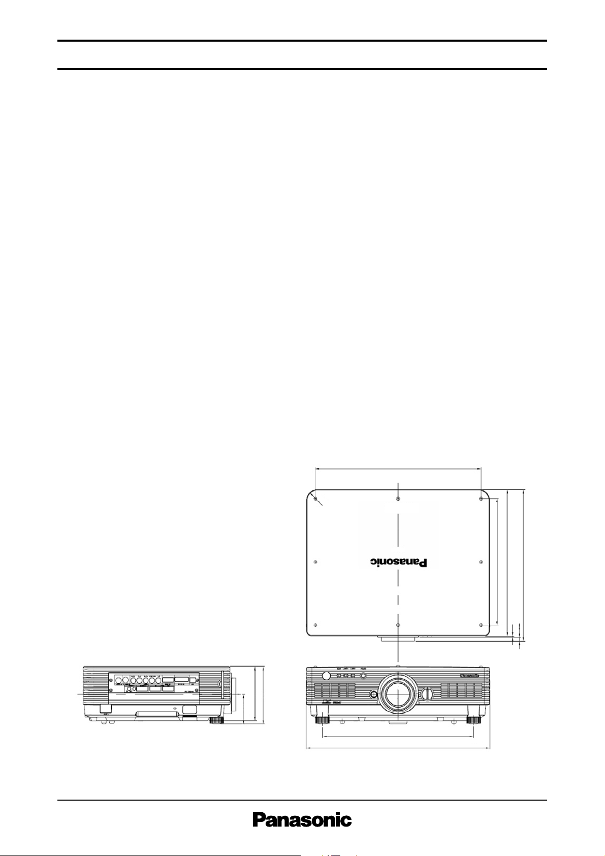
530 x 167 x 441 mm (20-7/8˝ x 6-9/16˝ x 17-3/8˝)
13.7 kg (30.2 lbs) (with supplied lens)
0°–45°C (32°–113°F)
20%–80% (no condensation)
3 V DC (AA battery x 2)
Approx. 30 m (98.4 feet) when operated from directly in front of the
signal receptor
51 x 176 x 22.5 mm (2˝ x 6-15/16˝ x 7/8˝)
134 g (4.7 oz) (including batteries)
Power cord, Wireless/wired remote control unit, Batteries for remote
control (x 2), Wire rope
ET-LAD40 (1 unit)
ET-LAD40W (set of two lamps)
ET-PKD56H (for high ceilings)
ET-PKD55S (for low ceilings)
ET-DLE100
ET-DLE200
ET-DLE300
ET-DLE400
ET-DLE050
86.5
(3-13/32)
157 (6-3/16)
167 (6-9/16)
R30
(1-3/16)
368 (14-1/2)
478.5
(18-27/32)
425 (16-23/32)
441 (17-3/8)
4 (5/32)
12 (15/32)
436 (17-5/32)
530 (20-7/8)
unit : mm (inch)
NOTE: This illustration is not drawn to scale.
Dimensions
Weights and dimensions shown are approximate. Specifications subject to change without notice.
*1 Values indicate overall average values of the product at the time of shipment and are stated based on JIS X 6911:2003 Data Projector
Specification Sheet Format. Measurement method and conditions are based on Appendix 2.
*2 The HD/SYNC and VD inputs do not accept the tri-level sync signal.
*3 Operation range differs depending on environments.
Page 4
S PEC F ILE
PT-D4000
DLP™Projectors
As of May 2007 < 4 >
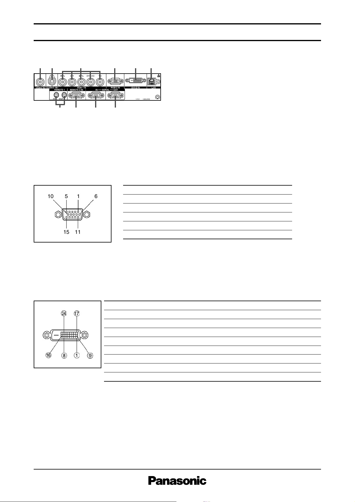
Terminals
RGB IN connector pin assignment
1 Video input
2 S-Video input
3 RGB 1 input
4 RGB 2 Input
5 DVI-D input
6 LAN connector
7 Remote 1 input and output
8 Remote 2 input
9 Serial input
10 Serial output
no.
1
2
3
4
5
no.
6
7
8
9
10
no.
11
12
13
14
15
signal
R/PR
G/Y
B/PB
GND
GND
signal
GND
GND
GND
NC
GND
signal
GND
NC
HD/SYNC
VD
NC
DVI-D output connector pin assignment
no.
1
2
3
4
5
6
7
8
no.
9
10
11
12
13
14
15
16
no.
17
18
19
20
21
22
23
24
signal
T, M, D, S data 2T, M, D, S data 2+
T, M, D, S data 2 shield
NC
NC
DDC clock
DDC clock
NC
signal
T, M, D, S data 1T, M, D, S data 1+
T, M, D, S data 1 shield
NC
NC
+5 V
GND
Hot plug detection
signal
T, M, D, S data 0T, M, D, S data 0+
T, M, D, S data 0 shield
NC
NC
T, M, D, S clock shield
T, M, D, S clock +
T, M, D, S clock -
1
78 9 10
23 456
Page 5

Upper edge of projected image Attachment
plate
261
(10-9/32˝)
*3
Lower edge of projected image
Projected image
L
L
109
(4-9/32˝)
76.5 (3˝)
157
(6-3/16˝)
87.5
(3-7/16˝)
L
Projected image
HH
S PEC F ILE
Upper edge of projected image
256
(10-3/32˝)
*1
*2
L
ower edge of projected image
P
rojected image
L
L
L
340–420
(13-3/8˝–
16-17/32˝)
417–497
(16-13/32˝–
19-9/16˝)
100
(3-15/16˝)
344
(13-17/32˝)
100
(3-15/16˝)
400
(15-3/4˝)
Projected image
HH
DLP™Projectors
Standard setting-up position (when installed using the ET-PKD56H)
PT-D4000
*3 When the lens protrudes to the maxi-
mum.
185 mm (7-9/32˝) with the supplied lens
177 mm (6-31/32˝) with the ET-DLE050
209 mm (8-7/32˝) with the ET-DLE100
208 mm (8˝-3/16˝) with the ET-DLE200
196 mm (7-23/32˝) with the ET-DLE300
196 mm (7-23/32˝) with the ET-DLE400
*4 Adjustable in 40 mm (1-9/16˝) steps.
unit : mm (inch)
Standard setting-up position (when installed using the ET-PKD55S)
CAUTION
The ET-DLE050 has a fixed short-focus lens. Therefore, the lens shift function provided in the main
unit cannot be used.
If the lens shift function is used, the corners of images may not be displayed or images may remain
out of focus in some cases.
As of May 2007 < 5>
*3 When the lens protrudes to the maxi-
mum.
180 mm (7-3/32˝) with the supplied lens
172 mm (6-25/32˝) with the ET-DLE050
204 mm (8-1/32˝) with the ET-DLE100
203 mm (8˝) with the ET-DLE200
191 mm (7˝-17/32˝) with the ET-DLE300
191 mm (7-17/32˝) with the ET-DLE400
unit : mm (inch)
NOTE:
Illustrations show the projector installed
using optional ceiling bracket.
This illustration is not drawn to scale.
Values shown are approximate.
The value for L (distance to screen) varies
slightly depending on the zoom lens characteristics. When the shortest projection
distance (min.) is used, a small amount of
distortion may occur in the image due to
the zoom lens characteristics.
Page 6

S PEC F ILE
PT-D4000
DLP™Projectors
As of May 2007 < 6 >
Projection distance for 4:3 aspect ratio screen
50
60
70
80
90
100
120
150
200
250
300
400
500
600
Screen
size
(inch,
diagonal)
min. max. min. max.
Zoom
Zoom
lenses
Fixed-focus
Fixed-
focus
lens
Distance to screen (L) Height from the edge
of screen to
center of lens (H)
min. max. min. max. min. max.
ET-DLE100
Zoom lens
Supplied lens ET-DLE200
Zoom lens
ET-DLE300
Zoom lens
ET-DLE400
Zoom lens
ET-DLE050
Fixed-focus
lens
–
–
–
–
–
–
–
–
–
–
–
–
–
–
0
0
0
0
0
0
0
0
0
0
0
0
0
0
0.38
0.46
0.53
0.61
0.69
0.76
0.91
1.14
1.52
1.91
2.29
3.05
3.81
4.57
0.794
0.960
1.126
1.292
1.458
1.624
1.956
2.454
3.284
–
–
–
–
–
0.381
0.457
0.533
0.610
0.686
0.762
0.914
1.143
1.524
–
–
–
–
–
1.4
1.7
1.9
2.2
2.5
2.8
3.3
4.1
5.5
6.9
8.3
11.0
13.8
16.6
1.8
2.1
2.5
2.9
3.3
3.6
4.4
5.5
7.3
9.2
11.1
14.8
18.5
22.2
1.9
2.2
2.6
3.0
3.3
3.7
4.5
5.6
7.4
9.3
11.1
14.8
18.5
22.3
2.4
2.8
3.3
3.8
4.3
4.8
5.8
7.3
9.7
12.2
14.6
19.5
24.4
29.3
2.5
3.0
3.5
4.0
4.5
5.0
6.0
7.5
10.1
12.6
15.1
20.1
25.2
30.2
4.0
4.8
5.6
6.5
7.3
8.1
9.8
12.2
16.4
20.5
24.6
32.8
41.1
49.3
3.9
4.7
5.5
6.3
7.1
7.9
9.5
11.8
15.8
19.8
23.8
31.7
39.7
47.6
6.0
7.2
8.4
9.7
10.9
12.1
14.6
18.3
24.5
30.6
36.8
49.1
61.4
73.7
6.0
7.1
8.3
9.5
10.7
11.8
14.2
17.7
23.6
29.5
35.4
47.1
58.9
70.6
8.2
9.9
11.5
13.2
14.8
16.5
19.8
24.7
32.9
41.2
49.4
65.9
82.3
98.8
50
60
70
80
90
100
120
150
200
250
300
400
500
600
Screen
size
(inch,
diagonal)
min. max. min. max.
Zoom
Zoom
lenses
Fixed-focus
Fixed-
focus
lens
Distance to screen (L) Height from the edge
of screen to
center of lens (H)
min. max. min. max. min. max.
ET-DLE100
Zoom lens
Supplied lens ET-DLE200
Zoom lens
ET-DLE300
Zoom lens
ET-DLE400
Zoom lens
ET-DLE050
Fixed-focus
lens
–
–
–
–
–
–
–
–
–
–
–
–
–
–
0
0
0
0
0
0
0
0
0
0
0
0
0
0
1.25
1.50
1.75
2.00
2.25
2.50
3.00
3.75
5.00
6.25
7.50
10.00
12.50
15.00
2.605
3.149
3.694
4.239
4.783
5.328
6.417
8.051
10.774
–
–
–
–
–
1.250
1.500
1.750
2.000
2.250
2.500
3.000
3.750
5.000
–
–
–
–
–
4.4
5.3
6.2
7.1
8.1
9.0
10.8
13.5
18.0
22.5
27.1
36.1
45.2
54.2
5.9
7.1
8.3
9.6
10.8
12.0
14.4
18.1
24.2
30.3
36.4
48.6
60.8
73.0
6.0
7.2
8.4
9.6
10.8
12.1
14.5
18.1
24.2
30.3
36.4
48.6
60.7
72.9
7.8
9.4
11.0
12.6
14.3
15.9
19.1
23.9
31.9
40.0
48.0
64.1
80.2
96.2
8.1
9.8
11.4
13.1
14.7
16.4
19.7
24.6
32.9
41.2
49.4
66.0
82.5
99.0
13.2
15.9
18.6
21.3
24.0
26.7
32.1
40.3
53.8
67.3
80.8
107.8
134.9
161.9
12.6
15.2
17.9
20.5
23.1
25.7
30.9
38.7
51.8
64.8
77.8
103.9
130.0
156.1
19.7
23.8
27.8
31.9
35.9
39.9
48.0
60.2
80.4
100.6
120.8
161.2
201.6
242.0
19.4
23.3
27.1
31.0
34.9
38.7
46.4
58.0
77.3
96.6
115.9
154.5
193.0
231.6
27.2
32.6
38.0
43.4
48.8
54.2
65.0
81.2
108.2
135.2
162.2
216.2
270.2
324.2
Projection distance for 4:3 aspect ratio screen
(feet)
(meters)
• The value for L (distance to screen) varies slightly depending on the zoom lens characteristics.
• At the shortest projection distance, the zoom lens characteristics may cause slight image distortion.
• When vertical keystone correction is used, the image is corrected in the direction that reduces its projected size.
• For the ET-DLE050, the height from the edge of the screen to the center of the lens (H) is 1/2 of the screen height.
• The brightness varies depending on the zoom settings.
Page 7

S PEC F ILE
PT-D4000
DLP™Projectors
As of May 2007 < 7 >
Calculation of the projection distance
For a screen size different from the above, use the equation below to calculate the projection distance.
Aspect ratio 4:3
minimum L (m) = (diagonal screen size in inches) x 0.0276 - 0.0452
maximum L (m) = (diagonal screen size in inches) x 0.0372 - 0.0478
minimum L (m) = (diagonal screen size in inches) x 0.0371 - 0.0507
maximum L (m) = (diagonal screen size in inches) x 0.0490 - 0.0500
minimum L (m) = (diagonal screen size in inches) x 0.0504 - 0.0657
maximum L (m) = (diagonal screen size in inches) x 0.0824 - 0.0758
minimum L (m) = (diagonal screen size in inches) x 0.0795 - 0.1380
maximum L (m) = (diagonal screen size in inches) x 0.1232 - 0.1310
minimum L (m) = (diagonal screen size in inches) x 0.1176 + 0.0244
maximum L (m) = (diagonal screen size in inches) x 0.1646 + 0.0651
(fixed focus) L (m) = (diagonal screen size in inches) x 0.0166 - 0.0361
ET-DLE100
Supplied lens
ET-DLE200
ET-DLE300
ET-DLE400
ET-DLE050
• Distances calculated with the above equations will include a slight error.
• When an SXGA signal is input, the left and right edges of the image are blanked, and the image is projected at a screen aspect ratio of 5:4.
• The brightness varies depending on the zoom setting.
H
(Width of
projected image)
V
(Height of
projected image)
0.5V
0.1H0.1H
Standard postition
of projected image
Shift range
Optical axis shift function allows to shift the
position of a projected image as shown.
Installable angle
Install the projector at an angle within the range shown below.
• Vertical direction
The projector may be installed at a vertical
angle of 360°.
• Horizontal direction
The projector may be installed at a horizontal
angle of ±10°.
Page 8

S PEC F ILE
PT-D4000
DLP™Projectors
As of May 2007 < 8 >
List of compatible signals
This projector supports RGB signals with horizontal frequencies of 15 to 91 kHz, vertical frequencies of
50 to 85 Hz and up to 150 MHz dot clock.
NOTE: The native resolution of this projector is 1,024 x 768 pixels. If the display resolution of the input signal is different from the
native resolution, image compression or expansion will be used to convert the input signal to a level within the native resolution.
1. The “i” appearing after the resolution indicates an interlaced signal.
2. The following symbols are used to indicate picture quality.
AA Maximum picture quality can be obtained.
A Signals are converted by the image processing circuit before picture is projected.
Display mode Display
NTSC/NTSC4.43/PAL-M/PAL60
PAL/PAL-N/SECAM
480i (525i)
576i (625i)
480p (525p)
576p (625p)
720/60p
720/50p
1080/60i
1080/50i
1080/60p
1080/50p
VGA400
VGA480
SVGA
MAC16
XGA
WXGA
MXGA
MAC21
MSXGA
SXGA
SXGA+
UXGA
resolution
(dots)
720 x 480i
720 x 576i
720 x 480i
720 x 576i
720 x 483
720 x 576
1,280 x 720
1,280 x 720
1,920 x 1,080i
1,920 x 1,080i
1,920 x 1,080
1,920 x 1,080
640 x 400
640 x 480
800 x 600
832 x 624
1,024 x 768
1,280 x 768
1,280 x 800
1,152 x 864
1,152 x 870
1,280 x 960
1,280 x 1,024
1,400 x 1,050
1,600 x 1,200
Scanning frequency
1
H
(kHz)V(kHz)
15.7
15.6
15.7
15.6
31.5
31.3
45.0
37.5
33.8
28.1
67.5
56.3
31.5
37.9
31.5
35.0
37.9
37.5
43.3
35.2
37.9
48.1
46.9
53.7
49.7
39.6
48.4
56.5
60.0
68.7
35.5
39.6
47.7
41.3
49.7
64.0
67.5
76.7
68.7
60.0
64.0
80.0
91.1
64.0
75.0
59.9
50.0
59.9
50.0
59.9
50.0
60.0
50.0
60.0
50.0
60.0
50.0
70.1
85.1
59.9
66.7
72.8
75.0
85.0
56.3
60.3
72.2
75.0
85.1
74.6
50.0
60.0
70.1
75.0
85.0
87.0
50.0
60.0
50.0
59.8
71.2
74.9
85.0
75.1
60.0
60.0
75.0
85.0
60.0
60.0
Dot clock
frequency
(MHz)
13.5
13.5
27.0
27.0
74.3
74.3
74.3
74.3
148.5
148.5
25.2
31.5
25.2
30.2
31.5
31.5
36.0
36.0
40.0
50.0
49.5
56.3
57.3
51.9
65.0
75.0
78.8
94.5
44.9
65.2
80.1
68.0
83.5
94.2
108.0
121.5
100.0
108.0
108.0
135.0
157.5
108.0
162.0
Picture
quality
-
-
A
A
A
A
A
A
A
A
A
A
A
A
A
A
A
A
A
A
A
A
A
A
A
A
A
AA
AA
AA
AA
AA
AA
A
A
A
A
A
A
A
A
A
A
A
A
A
A
Format
2
VIDEO/S-VIDEO
YP
BPR /RGB
BPR /RGB/DVI
YP
RGB
RGB/DVI
RGB
RGB/DVI
RGB
RGB/DVI
RGB
RGB/DVI
RGB
RGB/DVI
RGB
RGB/DVI
RGB
Page 9

S PEC F ILE
PT-D4000
DLP™Projectors
As of May 2007 < 9 >
Serial connector
The serial connector complies with RS-232C. To control the projector from a personal computer, commands must be input through communication software, based on the format and satisfying the communication conditions shown below.
Basic format
Transmission from the computer begins with STX, then the ID, command, parameter, and ETX are sent
in this order. Add parameters according to the details of control.
Communication conditions (factory setting)
Pin assignments and signal names
D-sub 9-pin (female)
Serial input
Description
NC
Send data
Receive data
Connected internally
Ground
Signal name
–
TXD
RXD
–
GND
No.
1
2
3
4
5
Description
NC
Connected internally
Connected internally
NC
Signal name
–
CTS
RTS
–
No.
6
7
8
9
Pin assignments and signal names
D-sub 9-pin (male)
Serial output
Description
NC
Receive data
Send data
Connected internally
Ground
Signal name
–
RXD
TXD
–
GND
No.
1
2
3
4
5
Description
NC
Connected internally
Connected internally
NC
Signal name
–
RTS
CTS
–
No.
6
7
8
9
CAUTIION
• It may not be possible to send or receive commands for about 10 to 60 seconds when the lamp is first turned on. If this
occurs, wait for 60 seconds, then try sending or receiving again.
• When sending multiple commands, be sure to wait for at least 0.5 second after receiving a response from the projector before
sending the next command.
• Additional time is sometimes required for response due to processing inside the projector. Set the time-out period for command response to 10 seconds or more.
Signal level
Synchronization method
Baud rate
Parity
Character length
Stop bit
X parameter
S parameter
RS-232C-compliant
Start-stop synchronization
9,600 bps
None
8 bits
1 bit
None
None
STX ETXC1 P1 P2 ... PnC2A D I1 I2 C3 : ;
Start
(1 byte)
ID 2 characters
(2 bytes)
ID designator:
01 to 64: Address number
0A to 0Z: Group ID
ZZ: All units (ID ALL)
Semicolon
(1 byte)
Colon
Command
(3 bytes)
(Control and/or query commands)
(1 byte)
Parameters
(undefined length)
End
(1 byte)
Page 10

S PEC F ILE
PT-D4000
DLP™Projectors
As of May 2007 < 10 >
Control commands
Adjustment mode
Cable specifications
PC (DTE)Projector
1
2
3
4
5
6
7
8
9
NC
NC
NC
NC
NC
NC
NC
NC
1
2
3
4
5
6
7
8
9
Command:Parameter FunctionItem Callback
1
POWER
FREEZE
PON
*
POF*
OFZ:0
1
OFZ:1
AUTO SETUP
SHUTTER
INPUT SELECT
OAS
OSH:0
*1/*
OSH:1*
IIS:RG1
2
1/*2
IIS:RG2
IIS:VID
IIS:SVD
IIS:DVI
TEST
OTS:00
OTS:01
OTS:02
OTS:03
OTS:05
OTS:07
OTS08
ON SCREEN
OOS:0
OOS:1
1
Do not send PON, POF, OSH, or OLP commands continuously in a short period of time. Doing so may burst the lamp or shorten the lamp replacement cycle.
*
2
When a command that cannot be executed during standby mode is sent, the projector will send an ER401 command in reply.
*
Power on
Standby power off
Freeze off
Freeze on
Auto setup
Shutter off
Shutter on
RGB 1
RGB 2
Video
S-Video
DVI
Exit test pattern
White (full on)
Black (full off)
Flag
Window
Focus
Color bar
On-screen display off
On-screen display on
PON
POF
OFZ:0
OFZ:1
OAS
OSH:0
OSH:1
IIS:RG1
IIS:RG2
IIS:VID
IIS:SVD
IIS:DVI
OTS:00
OTS:01
OTS:02
OTS:03
OTS:05
OTS:07
OTS08
OOS:0
OOS:1
Item Command: Parameter Callback: ParameterDescription Parameter value
PICTURE MODE
SYSTEM
DAYLIGHT
VIEW
COLOR
TINT
COLOR TEMP.
CONTRAST
BRIGHTNESS
SHARPNESS
SET DATE
SET TIME
VPM:NAT
VPM:STD
VPM:DYN
VPM:CIN
VPM:GRA
VXX:DLVI0=+00000
VXX:DLVI0=+00001
VXX:DLVI0=+00002
VXX:DLVI0=+00003
VCO:p1p2p3
VTN:p1p2p3
OTE:1
OTE:2
OTE:4
OTE:10
VCN:p1p2p3
VBR:p1p2p3
VSR:p1p2p3
TSD:y1y2y3y4m1m2d1d2w
TST:h1h2m1m2s1s2
Natural
Standard
Dynamic
Cinema
Graphic
Off
1
2
3
Color
Tint
Middle
High
User
Default
Contrast
Brightness
Sharpness
Date setting
Time setting
VPM:NAT
VPM:STD
VPM:DYN
VPM:CIN
VPM:GRA
VXX:DLVI0=+00000
VXX:DLVI0=+00001
VXX:DLVI0=+00002
VXX:DLVI0=+00003
VCO:p1p2p3
VTN:p1p2p3
OTE:1
OTE:2
OTE:4
OTE:10
VCN:p1p2p3
VBR:p1p2p3
VSR:p1p2p3
TSD:y1y2y3y4m1m2d1d2w
TST:h1h2m1m2s1s2
Min. Max.
–
–
–
–
–
–
–
–
–
1
1
–
–
–
–
1
1
0
200701011
000000
–
–
–
–
–
–
–
–
–
63
63
–
–
–
–
63
63
15
203512317
235959
Page 11

S PEC F ILE
PT-D4000
DLP™Projectors
As of May 2007 < 11 >
Status asking commands
Item Command: Parameter Function DescriptionCallback
POWER CONDITION
FREEZE
SHUTTER
INPUT SIGNAL
TEST
ON SCREEN
PICTURE MODE
SYSTEM
DAYLIGHT
VIEW
COLOR
TINT
COLOR TEMP.
CONTRAST
BRIGHTNESS
SHARPNESS
SET RUNTIME
LAMP ON TIME
(LAMP TIMER)
LAMP SELECT
VPS SYSTEM
TMP CHECK
GET DATE
GET TIME
QPW
QFZ
QSH
QIN
QTS
QOS
QPM
QVX:DLVI0
QVC
QVT
QTE
QVR
QVB
QVS
QST
Q$L:1
Q$L:2
QSL
QVY
QTM:0
QTM:1
QTM:2
QGD
QGT
Main power status
Freeze function status
Shutter function status
Input signal status
Test pattern status
On-screen display status
Picture mode status
System daylight view status
Color adjustment value
Tint adjustent value
Color temperature adjustment status
Contrast adjustment value
Brightness adjustment value
Sharpness adjustment value
Picture mode status
Lamp 1 run time
Lamp 2 run time
Lamp operation mode status
VPS system status
Temperature status
Date setting status
Time setting status
Standby (Off)
On
Off
On
Off
On
RGB 1
RGB 2
Video
S-Video
DVI
Exit test pattern
White (full on)
Black (full off)
Flag
Window
Focus
Color bar
Off
On
Natural
Standard
dynamic
Cinema
Graphic
Off
1
2
3
Middle
High
User
Default
00000h–99999h
0000h–9999h
0000h–9999h
Dual
Single
Lamp 1
Lamp 2
Slave
Master
p0 = Intake air
p1 = Exhaust air
p2 = DLP™ chip
yyyymmdd (day of week)
(*2)
hhmmss
(*3)
000
001
0
1
0
1
RG1
RG2
VID
SVD
DVI
0
1
2
3
5
7
8
0
1
NAT
STD
DYN
CIN
GRA
DLVI0=+00000
DLVI0=+00001
DLVI0=+00002
DLVI0=+00003
p1p2p3
p1p2p3
1
2
4
10
p1p2p3
p1p2p3
p1p2p3
p1p2p3p4p5
p1p2p3p4
p1p2p3p4
0
1
2
3
0
1
p1p2p3p4/p5p6p7p8
(*1)
y1y2y3y4m1m2d1d2w
h1h2m1m2s1s2
*
2
*
3
Day of week: Monday = 1, Tuesday = 2, ... Sunday = 7
*
1
p1p2p3p4: Celsius (°C), p5p6p7p8: Fahrenheit (°F)
Set the date and time to UTC (universal time coordinated).
Page 12

S PEC F ILE
PT-D4000
DLP™Projectors
As of May 2007 < 12 >
Parameter format
Command example
To set the on-screen display off, send the command as shown below.
NOTE: If a wrong command is received, the projector will send an ER401 command to the computer.
NOTE: When sending commands without parameters, a colon (:) is not necessary.
Parameter format Size (Byte) Difinition
<pl>
<off on>
<input signal>
<installation>
<language>
<power condition>
<lamp on time>
<lamp select>
<acctch>
<color temp>
<date>
<time>
3 (1 or 2 bytes also
possible when
under control)
1
3
1
3
3
4
1
4
2
9
6
Dicimal without signs: 0-999 (000, 001, 002...999)
Dicimal with signs: -99 to +99 (-99...-01, +00, +01, +02...+99)
Callback from the projector is 3 Byte.
0 = off, 1 = on
RG1 = computer 1, RG2 = computer 2, VID = video, SVD = S-Video,
DVI = DVI
0 = front, 1 = rear, 2 = ceiling and front, 3 = ceiling and rear
ENG = English, DEU = German, FRA = French, ESP = Spanish,
ITL = Italian, JPN = Japanese, CHI = Chinese, RUS = Russian, KOR = Korean
000 = standby power off, 001 = standby power on
Decimal without signs: 0000-9999 hours
0 = dual, 1 = single, 2 = lamp 1, 3 = lamp 2
Decimal without signs: 0000-9999 hours
1 = mid, 2 = high, 4 = user, 10 = default
y1y2y3y4m1m2d1d2w = year (y) month (m) day (d) day of week (w)
Day of week: Monday = 1, Tuesday = 2, ... Sunday = 7
h1h2m1m2s1s2 = hour (h) minute (m) second (s)
STX
Start Parameter End
ADZZ OOS : 30; ETX
ID Address Command
Page 13

S PEC F ILE
PT-D4000
DLP™Projectors
As of May 2007 < 13 >
Notes on Projector Placement and Operation:
The projector uses a high-wattage lamp that becomes very hot during operation. Please observe the
following precautions.
1. Never place objects on top of the projector while it is operating.
2. Make sure there is an unobstructed space of 500 mm or more around the projector’s exhaust
openings.
3. Do not stack projector units directly on top of one another. If two units must be stacked for back-
up use in ordinary projection, use a method as shown below and provide ample space between the
units to ensure that exhaust heat does not accumulate near the intake opening or around the units.
Dual stacked projection of the PT-D4000 is not recommended.
4. If the projector is placed in a box or enclosure, ensure the temperature of the air surrounding the
projector is between 0°C/32°F and 40°C/104°F *. Also make sure the projector’s intake and exhaust
openings are not blocked. Take particular care to ensure that hot air from the exhaust openings is
not sucked into the intake openings.
* Even when the ambient temperature near the intake opening is 40°C/104°F or lower, an accumulation of hot air inside the cabinet may
cause the protective circuit to activate and shut down the projector. Please give ample consideration to the design with regard to
ambient temperature conditions.
Operating the Projector Continuously:
1. If the projector is to be operated continuously 24 hours a day, use the dual-lamp optical system’s alter-
nating lamp operation (lamp changer) function. The projector cannot be operated continuously 24 hours
a day in dual-lamp mode.
Allow a minimum of two hours per day of non-operation time.
2. The lamp replacement cycle duration becomes shorter if the projector is operated repeatedly for short
periods.
DLP and the DLP logo are trademarks of Texas Instruments. UHM is a trademark of Matshushita Electic.
PJLink is a registered trademark, or a trademark application has been filed, in Japan, the United States, and other countries and regions.
VGA and XGA are registered trademarks of International Business Machines Corporation.
All other trademarks are the property of their respective trademark owners.
Direction of Air Intake and Exhaust
Intake
Exhaust
500 mm/19.2˝ or more 500 mm/19.2˝ or more* 500 mm/19.2˝ or more*
100 mm/
3.9˝ or more
Minimum distance when two units are used together.
*
Keep 300 mm/11.8˝ or more when a single unit is used.
Do not stack projector
units directly on top of
one another.
 Loading...