

Panasonic PT-61G41 Owner’s Manual

PanaSOnlc
ProjectionSystem
Operating Instructions
PT-46G41
PT-51G41 PT-61G41
PT-46G41C
Read these instructions completely be|ore opelatiny.
Contents subject to change without notice or obligation.
Copyright 1997 by Matsushita Electric Corporation
ot America. All rights reserved. Unauthorized
copying and distribution is a violation of law.
HnnteO In U.b._.
TQB2AA0105--2
Safety Instructions
WARNING
WARNING: To reduce the risk of electric shock do not remove cover or back. No
user-serviceable parts inside. Refer servicing to qualified service personnel.
The lightnin9 flash with ar-
is intended to tell the user
that parts inside the product
_ row-head wtthin a triangle _
are arisk of electric shock to
persons.
The exclamation point within
a triangle is intended to tell
the user that important oper-
ating and servicing instruc-
tions are in the papers with
the appliance.
Note To CATV System Installer: This reminder is provided to call the CATV system installer's attention to Article
820-40 of the NEC that provides guidelines for proper grounding and, in particular, specifies that the cable ground shall be
connected to the grounding system of the building, as close to the point of cable entry as practical.
Safety Instructions For Television Receivers
1. Read and apply the operating instructions provided with your television receiver.
2. Read all of the instructions given here and retain them for later use.
3. Unplug this television receiver from the wall outlet before cleaning. Do not use liquid or aerosol cleaners. Use a damp
cloth for cleaning.
4. Do not use attachments not recommended by the television receiver manufacturer as they may cause hazards.
5. Do not use this television receiver near water. For example: Avoid placing it near a bathtub, washbowl, kitchen sink, or
laundry tub, in a wet basement, or near a swimming pool, etc.
6. Do not place this television receiver on an unstable cart, stand or table. The television receiver may fall, causing serious
injury to a child or adult, and serious damage to the appliance. Use only with a cart or stand recommended by the
manufacturer, or sold with the television receiver. Wall or shelf mounting should follow the manufacturer's instructions,
and should use a mounting kit approved by the manufacturer.
6A. An appliance and cart combination should be moved with care. Quick stops, excessive force, and _J_'_,
uneven surfaces may cause the appliance and cart combination to overturn.
7. Slots and openings in the cabinet and the back or bottom are provided for ventilation, and to insure
reliable operation of the television receiver and to protect it from overheating. These openings must not be blocked or
covered. The openings should never be blocked by placing the television receiver on a bed, sofa, rug or other similar
surface. This television receiver should never be placed near or over a radiator or heat register. This television receiver
should not be placed in a built-in installation such as a bookcase unless proper ventilation is provided.
8. Operate only from the type of power source indicated on the marking label. If you are not sure of the type of power
supplied to your home consult your television dealer or local power company. For television receivers designed to
operate from battery power, refer to the operating instructions.
9. This television receiver is equipped with a polarized alternating-current line plug (a plug having one blade wider than the
other). This plug will fit into the power outlet only one way. This is a safety feature. If you are unable to insert the plug
fully into the outlet, try reversing the plug. If
the plug should still fail to fit, contact your
electrician to replace yourobsoleteoutlet. Do EXAMPLE OF ANTENNA GROUNDING AS
not defeat the safety purpose of the polarized PER(NEC)NATIONALELECTRICALCODE WIRE
plug.
10. Do not allow anything to rest on the power
cord. Do not locate this television receiver
where the cord will be abused by persons
walking on it.
11. Follow all warnings and instructions marked
on the television receiver.
12. Do not overload wall outlets and extension
cords as this can result in fire or electric
shock.
13. Never push objects of any kind into this
television receiver through cabinet slots as
they may touch dangerous voltage points or
short out parts that could result in a fire or
electric shock. Never spill liquid of any kind on
the television receiver.
_-,_i'-"_- ELECTRODE SYSTEM
GROUNDCLAMPS
POWER SERVICE GROUNDING
(NEC ART250, PARTH)
ANTENNA LEAD-IN
ANTENNA
DISCHARGE UNIT
(NEC SECTION 810-20)
,ROUNDING CONDUCTORS
(NEC SECTION 810-21)
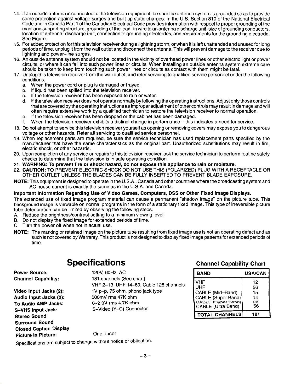
14. If an outside antenna isconnected to the television equipment, be sure the antenna system is grounded so as to provide
some protection against voltage surges and built up static charges. In the U.S. Section 810 of the National Electrical
Code and in Canada Part 1 of the Canadian Electrical Code provides information with respect to proper grounding of the
mast and supporting structure, grounding of the lead-in wire to an antenna discharge unit, size of grounding conductors,
location of antenna-discharge unit, connection to grounding electrodes, and requirements for the grounding electrode.
See Figure.
15. For added protection for this television receiver during a lightning storm, or when it is left unattended and unused for long
periods of time, unplug itfrom the wall outlet and disconnect the antenna. This will prevent damage to the receiver due to
lightning and power-line surges.
16. An outside antenna system should not be located in the vicinity of overhead power lines or other electric light or power
circuits, or where it can fall into such power lines or circuits. When installing an outside antenna system extreme care
should be taken to keep from touching such power lines or circuits as contact with them might be fatal.
17. Unplug this television receiver from the wall outlet, and refer servicing to qualified service personnel under the following
conditions:
a. When the power cord or plug is damaged or frayed.
b. If liquid has been spilled into the television receiver.
c. If the television receiver has been exposed to rain or water.
d. If the television receiver does not operate normally by following the operating instructions. Adjust only those controls
that are cove red by the operating instructions as improper adjustment of other controls may result in damage and will
often require extensive work by a qualified technician to restore the television receiver to normal operation.
e. If the television receiver has been dropped or the cabinet has been damaged.
f. When the television receiver exhibits a distinct change in performance - this indicates a need for service.
18. Do not attempt to service this television receiver yourself as opening or removing covers may expose you to dangerous
voltage or other hazards. Refer all servicing to qualified service personnel.
19. When replacement parts are required, be sure the service technician has used replacement parts specified by the
manufacturer that have the same characteristics as the original part. Unauthorized substitutions may result in fire,
electric shock, or other hazards.
20. Upon completion of any service or repairs to this television receiver, ask the service technician to perform routine safety
checks to determine that the television is in safe operating condition.
21. WARNING: To prevent fire or shock hazard, do not expose this appliance to rain or moisture.
22. CAUTION: TO PREVENT ELECTRIC SHOCK DO NOT USE THIS (POLARIZED) PLUG WITH A RECEPTACLE OR
OTHER OUTLET UNLESS THE BLADES CAN BE FULLY INSERTED TO PREVENT BLADE EXPOSURE.
NOTE: This equipment is designed to operate in the U.S.A., Canada and other countries where the broadcasting system and
AC house current is exactly the same as in the U.S.A. and Canada.
Important Information Regarding Use of Video Games, Computers, DSS or Other Fixed Image Displays.
The extended use of fixed image program material can cause a permanent "shadow image" on the picture tube. This
background image is viewable on normal programs in the form of a stationary fixed image. This type of irreversible picture
tube deterioration can be limited by observing the following steps:
A. Reduce the brightness/contrast setting to a minimum viewing level.
B. Do not display the fixed image for extended periods of time.
C. Turn the power offwhen not in actual use,
NOTE: The marking or retained image on the picture tube resultingfrom fixed image use isnot an operating defect and as
such is not covered by Warranty. This product is notdesigned to displayfixed image patterns for extended periods of
time.
Specifications
Power Source:
Channel Capability:
Video Input Jacks (2):
Audio Input Jacks (2):
To Audio AMP Jacks:
S-VHS Input Jack:
Stereo Sound
Surround Sound
Closed Caption Display
Picture In Picture:
Specifications are subject to change without notice or obligation.
120V, 60Hz, AC
181 channels (See chart)
VHF 2-13, UHF 14-69, Cable 125 channels
1V p-p, 75 ohm, phono jack type
500mV rms 47K ohm
O-2.0V rms 4.7K ohm
S-Video (Y-C) Connector
One Tuner
-3-
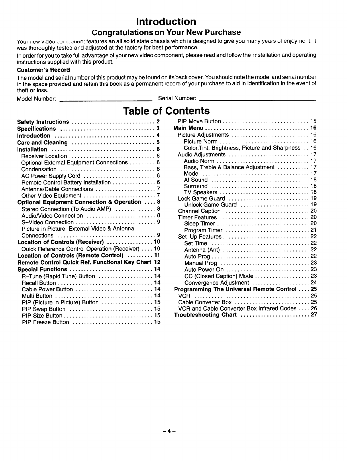
Channel Capability Chart
BAND US_CAN
VHF
UHF
CABLE (Mid-Band)
CABLE (Super Band)
CABLE (Hyper Band)
CABLE (Ultra Band)
TOTAL CHANNELS
12
56
15
14
28
56
181
Introduction
Congratulations on Your New Purchase
YOu_J_uwvlcleu _;u_pu__nt features an all solid state chassis which is designed to give you many yu_ ut enjoyn _f _1.It
was thoroughly tested and adjusted at the factory for best performance.
Inorder for you to take full advantage of your new video component, please read and follow the installation and operating
instructions supplied with this product.
Customer's Record
The model and serial number of this product may be found on its back cover. You should note the model and serial number
in the space provided and retain this book as a permanent record of your purchase to aid in identification in the event of
theft or loss.
Model Number:
Serial Number:
Table of Contents
Safety Instructions ............................. 2
Specifications ................................. 3
Introduction ................................... 4
Care and Cleaning ............................. 5
Installation .................................... 6
Receiver Location .............................. 6
Optional External Equipment Connections ......... 6
Condensation ................................. 6
AC Power Supply Cord ......................... 6
Remote Control Battery Installation ............... 6
Antenna/Cable Connections ..................... 7
Other Video Equipment ......................... 7
Optional Equipment Connection & Operation .... 8
Stereo Connection (To Audio AMP) .............. 8
AudioNideo Connection ........................ 8
S-Video Connection ............................ 9
Picture in Picture External Video & Antenna
Connections .................................. 9
Location of Controls (Receiver) ................ 10
Quick Reference Control Operation (Receiver) .... 10
Location of Controls (Remote Control) ......... 11
Remote Control Quick Ref, Functional Key Chart 12
Special Functions ............................. 14
R-Tune (Rapid Tune) Button ................... 14
Recall Button ................................. 14
Cable Power Button ........................... 14
Multi Button .................................. 14
PIP (Picture in Picture) Button .................. 15
PIP Swap Button ............................. 15
PIP Size Button ............................... 15
PIP Freeze Button ............................ 15
PIP Move Button .............................. 15
Main Menu .................................... 16
Picture Adjustments ........................... 16
Picture Norm ............................... 16
Color, Tint, Brightness, Picture and Sharpness .. 16
Audio Adjustments ............................ 17
Audio Norm ................................ 17
Bass, Treble & Balance Adjustment ........... 17
Mode ..................................... 17
AI Sound .................................. 18
Surround .................................. 18
TV Speakers ............................... 18
Lock Game Guard ............................ 19
Unlock Game Guard ........................ 19
Channel Caption ............................. 20
Timer Features ............................... 20
Sleep Timer ................................ 20
Program Timer ............................. 21
Set-Up Features .............................. 22
Set Time .................................. 22
Antenna (Ant) .............................. 22
Auto Prog .................................. 22
Manual Prog ............................... 23
Auto Power On ............................. 23
CC (Closed Caption) Mode ................... 23
Convergence Adjustment .................... 24
Programming The Universal Remote Control .... 25
VCR ........................................ 25
Cable Converter Box .......................... 25
VCR and Cable Converter Box Infrared Codes .... 26
Troubleshooting Chart ........................ 27
Care and Cleaning
Plastic Cabinets
Wipe thecabinet witha soft clothdampened with water or a milddetergent solution and wipe dry with a soft clean cloth.
Avoid excessive moisture. Do not use benzene, thinners or other petroleum based cleaners.
Wood Cabinets
When dusting or polishing the cabinet, use a clean soft cloth and stroke straight with the grain. An occasional coat of
furniture polish will help preserve the finish. Do not use benzene, thinners or other petroleum based cleaners. Do not
place objects made of plastic or rubber directly on top of the cabinet. A chemical reaction could result causing
permanent marring of the finish.
Remote Control Transmitter
Do not use benzene, thinners or other petroleum based cleaners to clean the Remote Control Transmitter. To clean,
wipe with a softcloth slightlymoistened with a mild detergent and then wipe dry with a softclean cloth..
Screen Caution
Your Projection screen may be marred by accidental contacts or improper cleaning.
Avoid BUMPING or SCRAPING the screen BY ANY OBJECTS.
The projection screen is a high precision lens system, but it is fully washable by using these following precautions.
1. NEVER use window or glass cleaner, laundry detergent, automatic dishwasher soap, abrasive cleaners, products
containing alcohol, ammonia or petroleum distillates.
2. NEVER rub across the screen in side to side motions.
3. NEVER use paper or other hard toweling materials.
Proper Cleaning Method
NOTE: Your projection screen is a high contrast black matrix type, which means it has black vertical stripeson itsface,
it will appear clark and this is normal.
A. Projection screens do notattract dirt from the air as televisions with picturetubes. Therefore, most likelyoccasional
dusting with a feather duster or very soft brush with straight downward strokes will suffice.
B. Infrequent washing may be desired and can be done with weak solution ofdish washing soap and a very soft lint
free cloth folded into a flat pad. Avoid excessive solution on the clothto prevent solution from running down below
the screen into the Receiver.
C°
Remember to wash only in an up and down motion using little pressure against the screen. NOTE that very fine
grooves exist between the black stripes which actually pass the picture to you. Improper cleaning can leave foreign
deposits in these grooves and impair your viewing pleasure. Marring and scuffing will in a like manner produce
imperfections upon your viewing conditions, so remember to guard against unnecessary screen contacts.
-5-
Installation
Receiver Location
This unit can be used as an entertainment center. Consult your dealer for available options.
Locate for comfortable viewing. Avoid placing where sunlight or other bright light (including reflections) will fall on the
soFeen.
Use of some types of fluorescent lighting can reduce remote control transmitter range.
Adequate ventilation is essential to prevent internal component failure. Keep away from areas of excessive heat or
moisture.
To insure optimum color purity do not position magnetic equipment (motors, fans, other speakers, etc.) nearby.
Optional External Equipment Connections
The Video/Audio connections between components can be made with shielded video and audio cables. For best perfor-
mance, video cables should utilize 75 ohm coaxial shielded wire. Cables are available from your dealer or electronic
supply house.
Before you purchase any cables, be sure you know what type of output and input connectors your various components
require. Also determine the length of cable you'll need.
Condensation
When the set is moved into a warm room from a cold area, the picture may become out of focus because of
condensation on the lens surface due to the temperature change, Picture will become clear when the set
reaches the same temperature of the surrounding area,
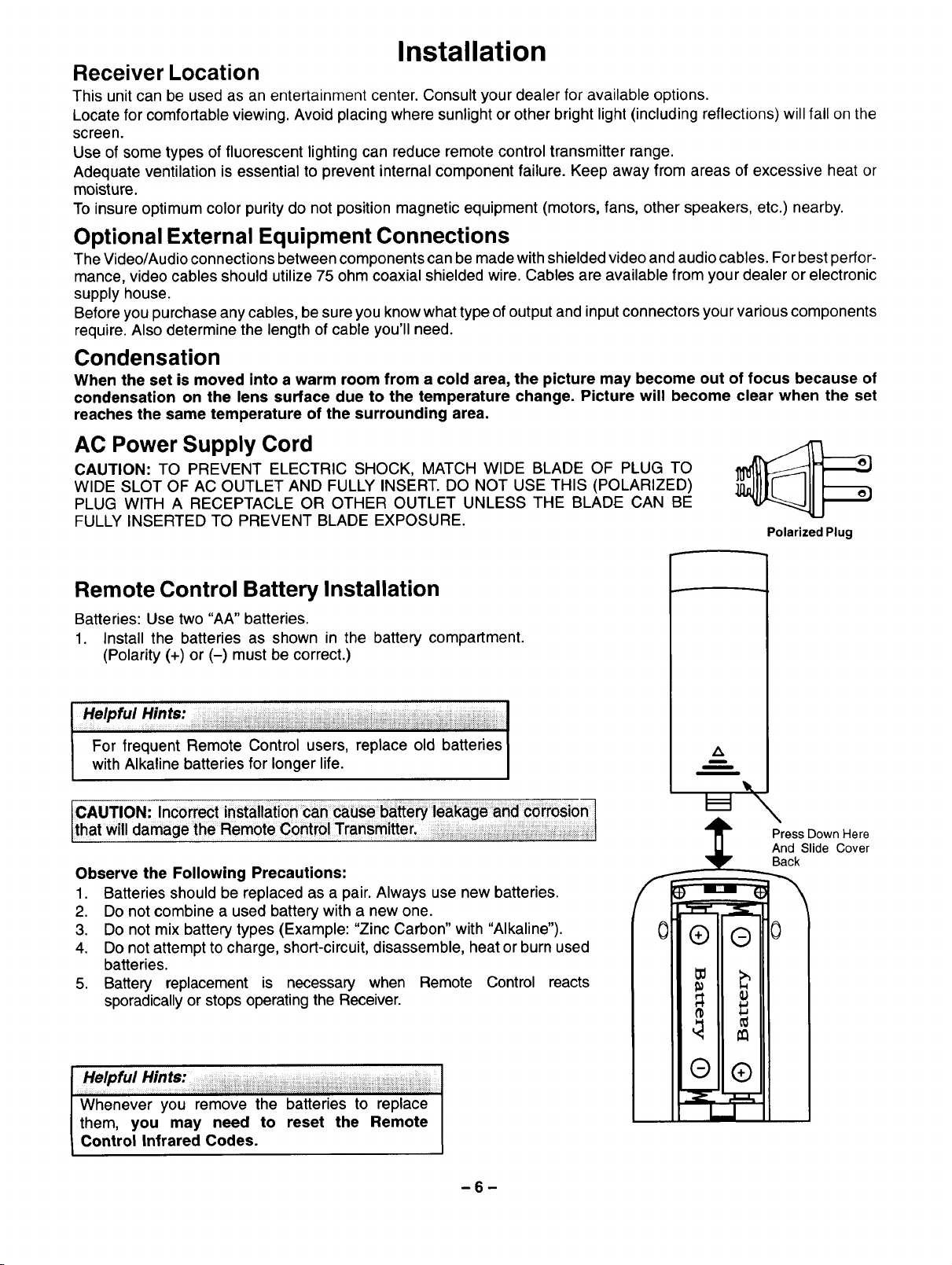
AC Power Supply Cord
CAUTION: TO PREVENT ELECTRIC SHOCK, MATCH WIDE BLADE OF PLUG TO
WIDE SLOT OF AC OUTLET AND FULLY INSERT. DO NOT USE THIS (POLARIZED)
PLUG WITH A RECEPTACLE OR OTHER OUTLET UNLESS THE BLADE CAN BE
FULLY INSERTED TO PREVENT BLADE EXPOSURE.
Polarized Plug
Remote Control Battery Installation
Batteries: Use two "AA" batteries.
1. Install the batteries as shown in the battery compartment.
(Polarity (+) or (-) must be correct.)
For frequent Remote Control users, replace old batteries
with Alkaline batteries for longer life.
Observe the Following Precautions:
1. Batteries should be replaced as a pair. Always use new batteries.
2. Do not combine a used battery with a new one.
3. Do not mix battery types (Example: "Zinc Carbon" with "Alkaline").
4. Do not attempt to charge, short-circuit, disassemble, heat or burn used
batteries.
5. Battery replacement is necessary when Remote Control reacts
sporadicallyor stops operatingthe Receiver.
z_
m
/
m
,4_ Press Down Here
And Slide Cover
Installation (cont.)
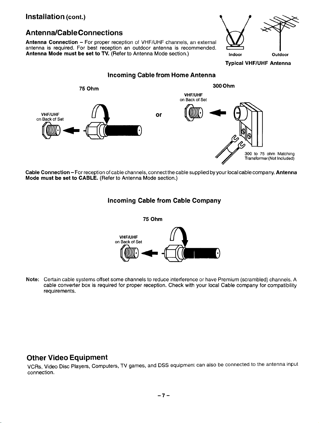
Antenna/CableConnections
Antenna Connection - For proper reception of VHF/UHF channels, an external
antenna is required. For best reception an outdoor antenna is recommended.
Antenna Mode must be set to TV. (Refer to Antenna Mode section.)
Incoming Cable from Home Antenna
Indoor Outdoor
Typical VHF/UHF Antenna
75 Ohm
VHF/UHF
onBackofSet
VHF/UHF
on Back of Set
Cable Connection - For reception of cable channels, connect thecable supplied by your local cable company. Antenna
Mode must be set to CABLE. (Refer to Antenna Mode section.)
or
300 Ohm
300 to 75 ohm Matching
Transformer (Not Included)
Incoming Cable from Cable Company
75 Ohm
VHF/UHF
on Back of Set
@...
Note: Certain cable systems offset some channels to reduce interference or have Premium (scrambled) channels. A
cable converter box is required for proper reception. Check with your local Cable company for compatibility
requirements.
Other Video Equipment
VCRs, Video Disc Players, Computers, TV games, and DSS equipment can also be connected to the antenna input
connection.
Optional Equipment Connection and Operation
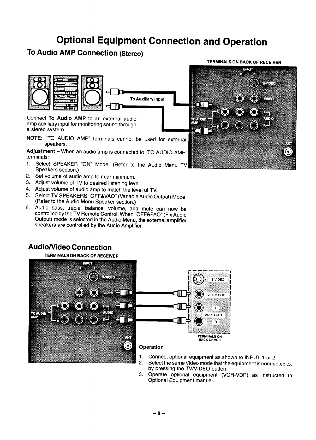
To Audio AMP Connection (Stereo)
To Auxiliary Input
Connect To Audio AMP to an external audio
amp auxiliary input for monitoring sound through
a stereo system.
NOTE: 'qO AUDIO AMP" terminals cannot be used for external
speakers.
Adjustment - When an audio amp is connected to "TO AUDIO AMP"
terminals:
1. Select SPEAKER "ON" Mode. (Refer to the Audio Menu TV
Speakers section.)
2. Set volume of audio amp to near minimum.
3. Adjust volume of TV to desired listening level.
4. Adjust volume of audio amp to match the level of TV.
5. Select TV SPEAKERS "OFF&VAO" (Variable Audio Output) Mode.
(Refer to the Audio Menu Speaker section.)
6. Audio bass, treble, balance, volume, and mute can now be
controlled by the TV Remote Control. When "OFF&FAO" (Fix Audio
Output) mode is selected in the Audio Menu, the external amplifier
speakers are controlled by the Audio Amplifier.
TERMINALS ON BACK OF RECEIVER
Audio/Video Connection
TERMINALS ON BACK OF RECEIVER
:1
S-VIDEO
VIDEO OUT
AUDIO OUT
TERMINALS ON
BACK OF VCR
Operation
1. Connect optional equipment as shown to INPUI 1 or 2.
2. Select the same Video mode that the equipment isconnected to,
by pressing the TVNIDEO button.
3. Operate optional equipment (VCR-VDP) as instructed in
Optional Equipment manual.
-8-
Optioi=al Equlpi.unt Connection and Operation (cont.)
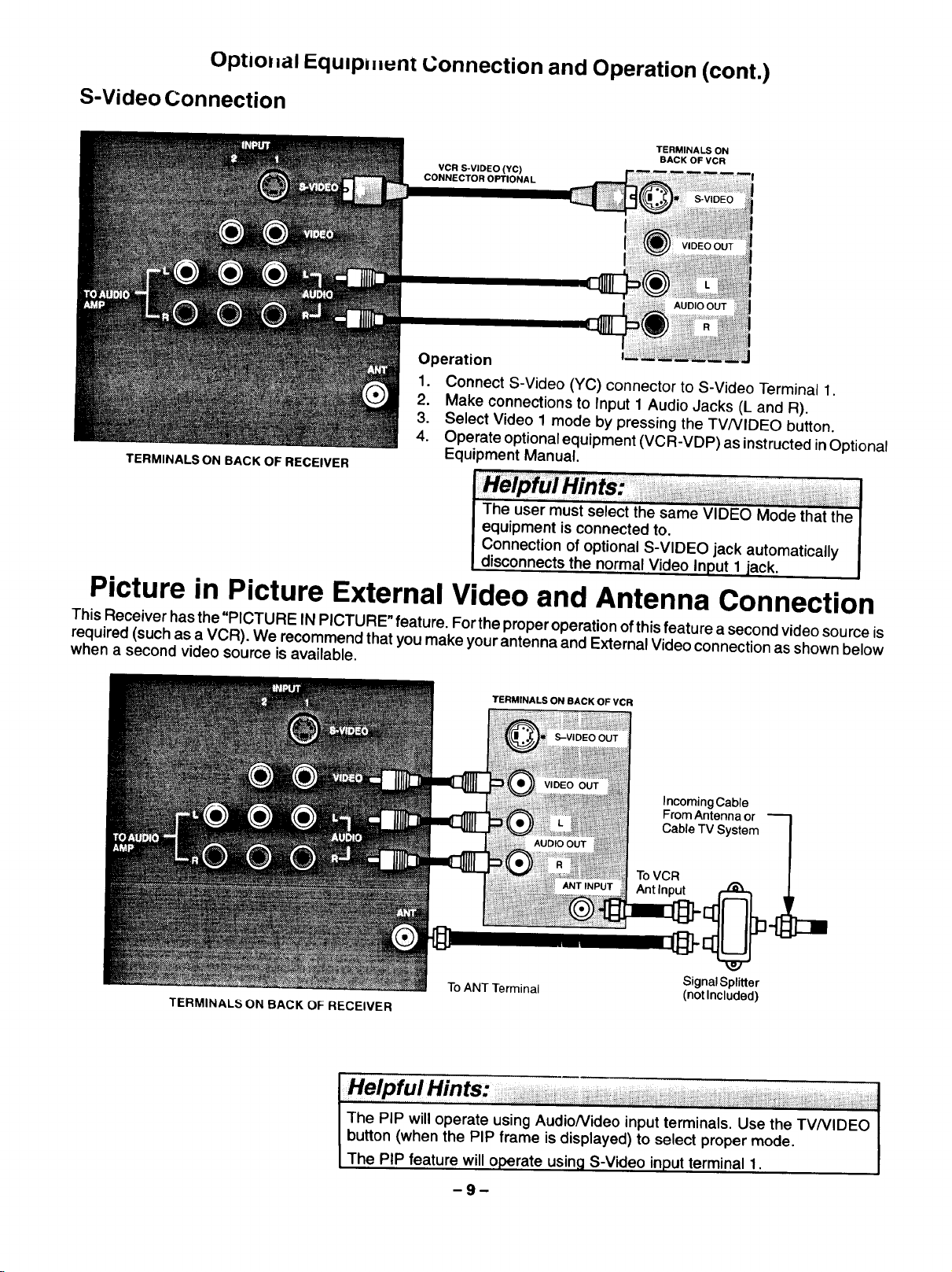
S-Video Connection
TERMINALS ON BACK OF RECEIVER
TERMINALS ON
VCR S-VIDEO (YC)
CONNECTOR OPTIONAL
Operation
1. Connect S-Video (YC) connector to S-Video Terminal 1.
2. Make connections to Input 1 Audio Jacks (L and R).
3. Select Video 1 mode by pressing the TV/VIDEO button.
4. Operate optional equipment (VCR-VDP) as instructed inOptional
Equipment Manual.
The user must select the same VIDEO Mode that the I
equipment is connected to.
Connection of optional S-VIDEO jack automatically
disconnects the normal Video Input 1 jack,
BACK OF VCR
AUDIO OUT
I
Picture in Picture External Video and Antenna Connection
This Receiver has the "PICTURE IN PICTURE" feature. For the proper operation of this feature a second video source is
required (such as a VCR). We recommend that you make your antenna and External Video connection as shown below
when a second video source is available.
TERMINALS ON BACK OF VCR
Incoming Cable
From Antenna or
Cable TV System
To VCR
Ant Input
To ANT Terminal (not Included)
TERMINALS ON BACK OF RECEIVER
Signal Splitter
button (when the PIP frame is displayed) to select proper mode.
I The PIP will operate using AudioNideo input terminals. Use the TVNIDEO
The PIP feature will operate using S-Video input terminal 1.
--9--
 Loading...