

Panasonic PT-M5131X, PT-M5131V, PT-61D31X, PT-51G36, PT-61D31V User Manual

Color Video Projection System
Operating Instructions
®
PT-51G36
PT-M5131V
PT-M5131X
PT-61D31V
PT-61D31X
For assistance, please call: 1-888-VIEW-PTV or send
e-mail to: consumerproducts@panasonic.com
TQB2AA0382 10112
PRINTED IN MEXICO
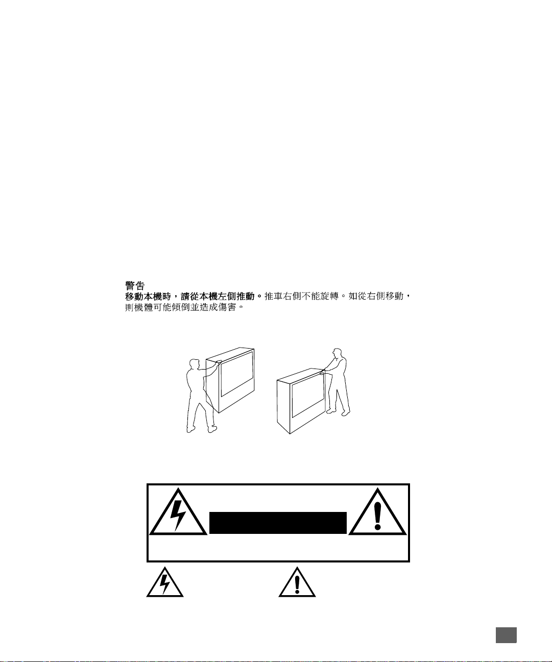
:$51,1*
7R PRYH VHW SXVK IURP OHIW VLGH RI VHW
GR QRW SLYRW LQ DOO GLUHFWLRQV 6HW FDQ WLS RYHU LI PRYHG IURP
ULJKW VLGH ZLWK ULVN RI SHUVRQDO LQMXU\
&DVWHUV RQ ULJKW VLGH
$'9(57(1&,$
3DUD PRYHU HO FRQMXQWR HPSXMH GHVGH HO ODGR L]TXLHUGR GHO
PLVPR
/RV URODQDV GH OD GHUHFKD QR VRQ SLYRWDQWHV HQ WRGDV
ODV GLUHFFLRQHV (O FRQMXQWR VH SXHGH WXPEDU VL VH OR PXHYH
GHVGH HO ODGR GHUHFKR FRUULHQGR DVt HO ULHVJR GH VXIULU GDxRV
SHUVRQDOHV
0LVH HQ JDUGH
/RUV GX GpSODFHPHQW GX WpOpYLVHXU OH SRXVHU VXU VRQ F{Wp
JDXFKH
WRXWHV OHV GLUHFWLRQV O·DSSDUHLO SRXUUDLW WRPEHU V·LO HVW SRXVVp
GH FH F{Wp HW FDXVHU DLQVL GHV ULVTXHV GH EOHVVXUH
/HV URXOHWWHV GX F{Wp GURLW QH SRXYDQW WRXUQHU GDQV
WARNING
RISK OF ELECTRIC SHOCK
DO NOT OPEN
WA RNIN G: To reduce the risk of electric shock do not remove cover or back.
No user-serviceable parts inside. Refer servicing to qualified service personnel.
The lightning flash with arrow
head within a triangle is
intended to tell the user that
parts inside the product are a
risk of electric shock to persons.
WARNING: To prevent fire or shock hazard, do not expose this appliance
to rain or moisture.
The exclamation point within a
triangle is intended to tell the
user that important operating
and servicing instructions are in
the papers with the appliance.
1

T
ABLE OF CONTENTS
Ta ble of Contents
Feature Comparison Chart ......................................3
Congratulations........................................................4
Customer Record .................................................. ...... ....... ...... 4
Care and Cleaning ...................................................................4
Specifications ...........................................................................4
Installation.................................................................5
Television Location...................................................................5
Optional Cable Connections.....................................................5
AC Power Supply Cord ............................................................5
Cable / Antenna Connection ....................................................5
Optional Equipment Connections.............................................6
VCR Connection.......................................................................6
Cable Box Connection .............................................................7
VCR and Cable Box Connection .............................................8
Amplifier Connection (To Audio Amp) .....................................9
Digital TV - Set-Top (DTV-ST B) Connection or DVD Player
Connection (some models)..................................................10
Picture In Picture (PIP) Operation..........................................11
Roller Guide Menu™Navigation............................12
Remote Control Guide............................................................12
Roller Guide Feature Chart....................................13
Special Features.....................................................16
Menu Languages....................................................................16
Program Channels .................................................................16
Closed Captioning..................................................................17
Closed Caption on Mute.........................................................17
Convergence 1.......................................................................18
Convergence 2.......................................................................19
Sleep Timer........................................ ...... ....... ...... ...... ...........20
Timer 1 and 2 .........................................................................20
Picture Adjustments ...............................................................21
Favorite Channels and Captions............................................21
Lock ............................... ....................................... .................22
Troubleshooting Chart...........................................23
Read these instructions completely before operating TV.
Contents are subject to change without notice or obligation.
Copyright 2001 by Matsushita Electric Corporation of America. All rights reserved.
Unauthorized copying and distribution is a violation of law.
2
F
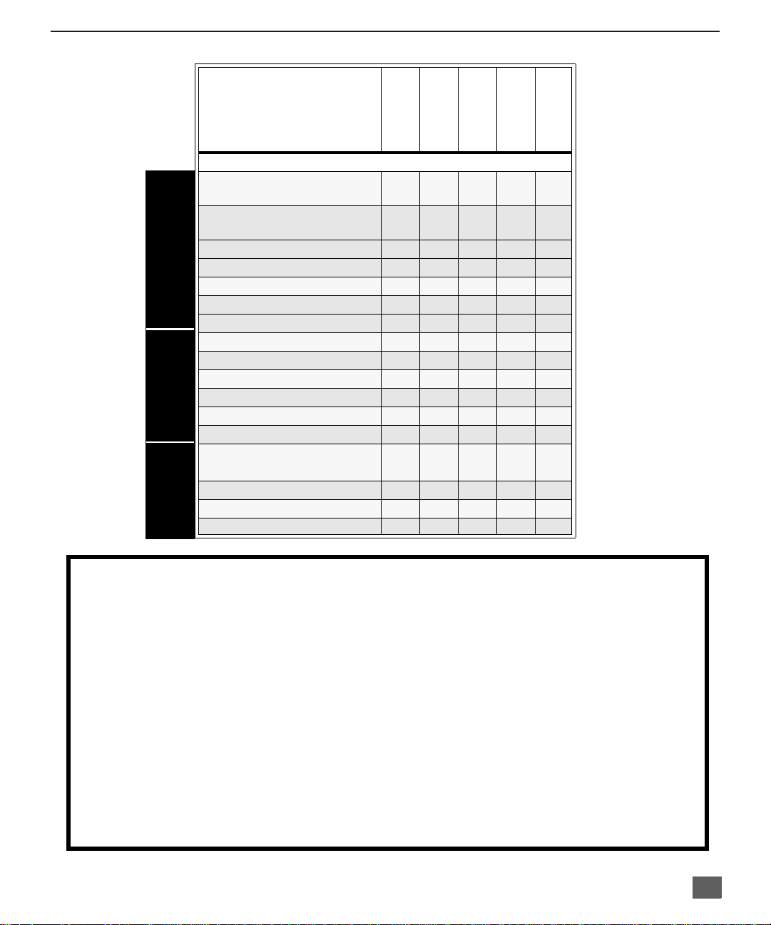
Feature Comparison Chart
MODELS
EATURE COMPARISON CHART
SPECIAL
FEATURES
AUDIO
A/V
JACKS
PT-51G36
PT-M51D31X
PT-M51D31V
FEA TURES
MENU LANGUAGE
ENG/SPAN/FR
PROTECTIVE
SCREEN
2 TUNER PIP
CLOSED CAPTIONING
V-CHIP CAPABILITY
2RF
VIDEO NORM
AUDIO NORM
STEREO
AI SOUND
BASS/BALANCE/TREBLE
SURROUND
NUMBER OF SPEAKERS 2 2 2 2 2
A/V IN
(REAR/FRONT)
AUDIO OUT
S-VHS INPUT
COMPONENT INPUT
r r r r r
r r r r r
r r r r r
r r r r r
r r r r r
r r r r r
r r r r r
r r r r r
r r r r r
r r r r r
r r r r r
r r r r r
3
(2/1)3(2/1)3 (2/1)3 (2/1)3 (2/1)
r r r r r
r r r r r
r r r r
PT-61D31V
PT-61D31X
IMPORTANT INFORMATION REGARDING THE USE OF VIDEO GAMES, COMPUTERS, OR
OTHER FIXED IMAGE DISPLAYS.
WARNING: The marking or retained image on the picture tube resulting from viewing fixed
image is not an operating defect and as such is not covered by Warranty.
The projection television is designed to display constantly moving images on the screen.
Continuous viewing of stationary images such as letterbox pictures on standard screen TVs (wit h
top/bottom bars), n on-expanded s tandard (4:3) pictures on wide screen T Vs (with side bars shown
on each side o f an image), stock mark et report bars (ticker run ning at the bottom of the screen),
video game patterns, fixed scoreboards, bright station logos, on-line (internet) or repetitive computer
style patterns should be limited.
The extended use o f fixed image program material can cause a per manent picture tube dam age,
shown as a “shado w image” viewable on normal pr ograms. This type of irreversibl e picture tube
deterioration can be limited by performing the following steps:
• Limit the display of fixed image program material to no more than 15% of total viewing time per week.
• Turn the power off when not in use.
3

C
ONGRATULATIONS
Congratulations
Your new Projection Television (PTV) features state-of-the-art technology for high
quality picture and sound with complete audio/video connections for your home
theater system. Your PTV is designed to give you many years of enjoymen t. It was
thoroughly tested and tuned at the factory for best performance.
Customer Record
The model and serial number of this product are located on the back of the TV. You should
note the model and serial number in the space provided and retain as a permanent record
of your purchase. This will aid in identification in the event of theft or loss.
Care and Cleaning
Projection Screen (Turn PTV Off)
The projection scr een is a high precision l ens system wh ich has a p rotective scr een.
The protective screen is fully washable with the following precautions:
r Use a mild soap solution or window cleaner and a clean cloth.
r Avoid excessive moisture and wipe dry.
r Avoid bumping or scraping the screen.
Note: Do not spray any type of cleaning fluid directly on the screen.
Cabinet and Remote Control
r For cabinets and remote control, use a soft c loth dampened with water or a mild
r Do not use benzene, thinner or other petroleum based products.
Specifications
Power Source
Model
Number
Serial
Number
• DO NOT USE ABRASIVE CLEANERS.
• Do not use laundry detergent or automatic dishwasher soap.
• Do not use alcohol, ammonia, or petroleum based products.
• Prevent solution from running into the receiver below.
detergent solution. Avoid excessive moisture and wipe dry.
PT-51G36 (3.3A)
PT-M51D31V(3.3A)
PT-61D31V (3.3A)
PT-M51D31X (3.3A)
PT-61D31X (3.3A)
Channel Capability - 181 VHF-12; UHF-56; Cable-113
Video Input Jacks 1Vp-p, 75 Ohm, Phono Jack Type
Audio Input Jacks 500mV RMS 47K Ohm
To Audio AMP Jack 0-2.0V RMS 4.7K ohm
DTV Input (Y / PB / PR)
S-Video Input Jacks S-Video (Y-C) Connector
120V AC, 60Hz
127V AC, 60Hz
75 Ohm, Phono Jack Type
Specifications are subject to change without notice or obligation.
4
Installation
I
Television Location
This unit can be used as an entertainment center. Consult your dealer for available options.
r Avoid excessive sunlight or bright lights, including reflections.
r Keep away from excessive heat or moisture. Inadequate ventilation may cause internal
component failure.
r Fluorescent lighting may reduce remote control transmitting range.
r Keep away from magnetic equipment, including motors, fans and external sp eakers.
Optional Cable Connections
Shielded audio and video cables should be used between components. For best results:
r Use 75-ohm coaxial shielded cables.
r Use appropriate input and output connectors, that match your component connectors.
r Avoid long cables to minimize interference.
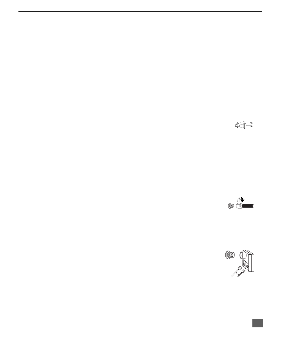
AC Power Supply Cord
CAUTION: TO PREVENT ELEC TRIC S HOCK M ATCH WIDE BLADE OF PL UG TO
WIDE SLOT OF AC OUTLET AND FULLY INSERT. DO NOT USE A PLUG WITH A
RECEPTACLE OR OTHER OUTLET UNLESS THE BLADE CAN BE FULLY
INSERTED TO PREVENT BLADE EXPOSURE.
PROTECT POWER CORDS FROM BEING WALKED ON, ROLLED OVER,
CRIMPED, BENT OR PINCHED, PARTICULARLY AT PLUGS, CONVENIENCE
RECEPTACLES, AND THE POINT WHERE THEY EXIT FRO M THE APPARATUS.
I
NSTALLATION
Polarized plug
Cable / Antenna Connection
For proper reception, either a cable or antenna connection is required.
Cable Connection
Connect the cable supplied by your local cable company to ANT1
connection on back of tele visio n. Sele ct cab le mod e and AN T1 in SET UP
menu under Prog Chan (Program Channels).
Note: A cable converter box may be required for proper recept ion. Check w ith
your local cable company for compatibility requirements.
Antenna Connections
• For proper reception of VHF/UHF channels, an external antenna is required. For
best reception an outdoor antenna is recommended.
• Connect home antenna to ANT1 connection on back of
television. Select T V mode a nd ANT1 i n the SET UP menu
under Prog Chan.
Note: Cable Mode is preset at the factory. Antenna users must change to TV
mode and select ANT1 in the Set Up Menu under Prog Chan.
Incoming Cabl e from
Cable Company
75 Ohm VHF/UHF
on back of TV
ncoming Cable from
Home Antenna
5
I
NSTALLATION
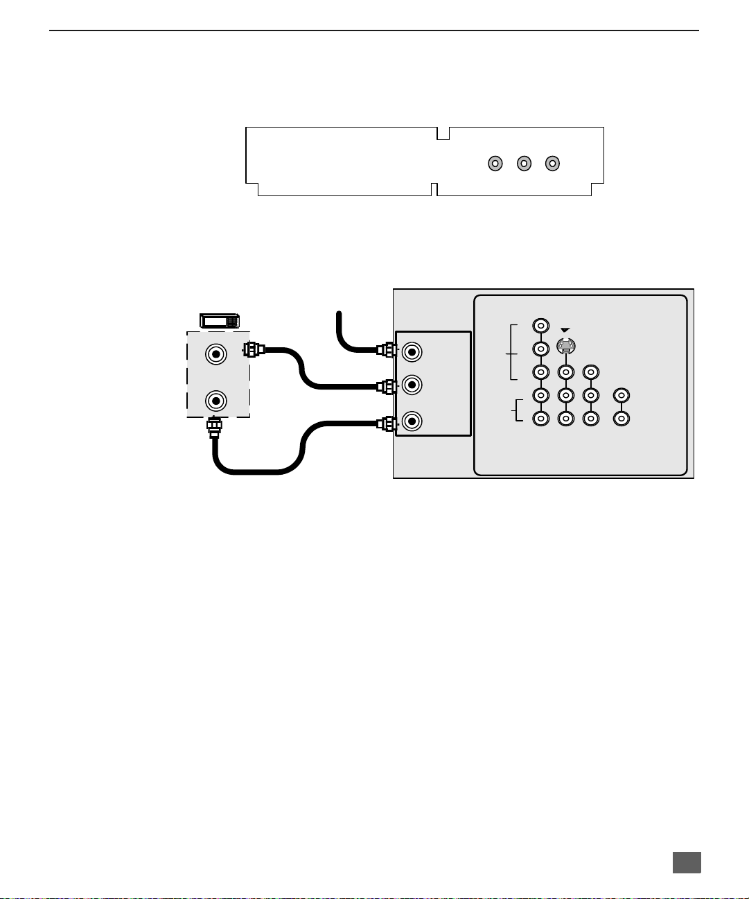
Optional Equipment Connections
VCR Connection
Follow this diagram when connecting your television to a VCR only.
VCR
VIDEO OUT
AUDIO
COMPONENT
VIDEO INPUT
Y
P
B
P
R
L
R
S-VIDEO
INPUT 1INPUT
2
VIDEO
TO AUDIO
AMP
AUDIO OUT
ANT OUT
L
R
ANT IN
CABLES NOT SUPPLIED
incoming
Cable
ANT 1
SPLIT
OUT
ANT 2
VIDEO
CONNECTIONS ON BACK OF TV (may vary)
Note: The remote control must be prog rammed with supplied codes to operate the VCR. See
Programming the Remote Control in the Remote Control Quick Reference Guide.
Viewing a television program
Procedure
1. Select ANT1 in the SET UP menu under Prog Chan (Program Channels).
2. Tune the television to the television program you want to vi ew.
Viewing a video
Procedure
r
Option A
1. Select ANT1 in the SET UP menu under Prog Chan (Program Channels).
2. Press the TV/VIDEO button on the remote control to select the video input (VIDEO 1,
VIDEO 2, etc.) connecte d to your VCR.
3. Begin the video.
r
Option B
1. Select ANT2 in the SET UP menu under Prog Chan (Program Channels).
2. Tune the television to Ch annel 3 or 4, depending on your VC R .
3. Begin the vide o.
Recording a television program
Procedure
r
Option A (Recording and viewing the same program)
1. Select ANT2 in the SET UP menu under Prog Chan (Program Channels).
2. Tune the television to Ch annel 3 or 4, depending on your VC R .
3. Using the VCR, tu ne to t he t el ev is io n pr ogram you want to record.
4. Begin recording.
r
Option B (Recording one pr ogram while viewing another program)
1. Select ANT1 in the SET UP menu under Prog Chan (Program Channels).
2. Press the TV/VIDEO button on the remote control to select the video input (VIDEO 1,
VIDEO 2, etc.) connecte d to your VCR.
3. Using the VCR, tu ne to t he t el ev is io n pr ogram you want to record.
4. Begin recording.
5. Press the TV/VIDEO button on the remote control to switch back to TV mode.
6. Tune the television to the television program you want to vi ew.
6
Optional Equipment Connections (Cont.)
Open the door on the TV front panel to use the connections for your optional equipment
(Palmcorder, VCR, or other video components). Select input 3 mode by pressing TV/VIDEO
.
button
CONNECTIONS ON FRONT OF TV (may vary)
Cable Box Connection
Follow this diagram when connecting your television to a cable box only.
CABLE BOX Incoming Cable
I
NSTALLATION
INPUT 3
VIDEO L-AUDIO-R
CONNECTIONS ON BACK OF TV (may vary)
AUDIO
COMPONENT
VIDEO INPUT
Y
P
B
P
R
L
R
S-VIDEO
INPUT 1INPUT
2
VIDEO
TO AUDIO
AMP
ANT IN
ANT OUT
CABLES NOT SUPPLIED
ANT 1
SPLIT
OUT
ANT 2
VIDEO
Note: The remote control must be programmed with supplied codes to operate the cable
box. See Programming the Remote Control in the Remote Control Quick Reference
Guide.
Viewing a premium (scrambled) cable channel
Procedure
1. Select ANT2 in the SET UP menu under Prog Chan (Program C hannels).
2. Tune the television to Channel 3.
3. Using the cable box, tune to the premium cable channel you want to view.
Note: To use speci al featu res suc h as Favori te Cha nnels and Chann el Ca ptions (se e Specia l
Features section for more information), ANT1 must be selected in the SET UP menu
under Prog Chan.
7
I
NSTALLATION
Optional Equipment Connections (Cont.)
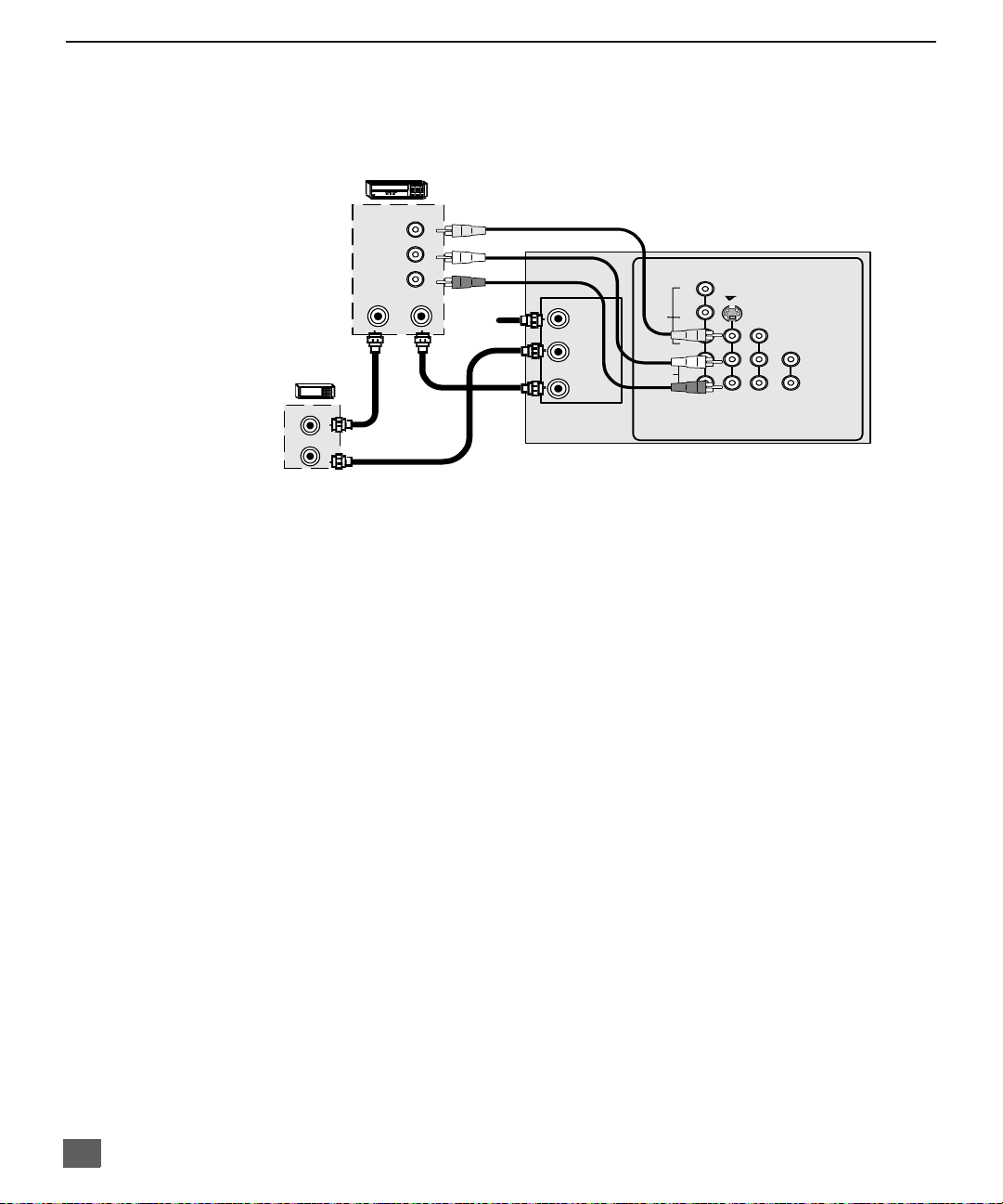
VCR and Cable Box Connection
Follow this diagram when connecting your television to both a VCR and a cable box.
VCR
CONNECTIONS ON BACK OF TV (may vary)
Y
ANT 1
SPLIT
OUT
ANT 2
VIDEO
AUDIO
COMPONENT
VIDEO INPUT
P
B
P
R
L
R
S-VIDEO
INPUT 1INPUT
2
VIDEO
TO AUDIO
AMP
CABLE
BOX
ANT OUT
ANT IN
ANT IN
VIDEO OUT
AUDIO OUT
ANT OUT
L
R
Incoming
Cable
CABLES NOT SUPPLIED
Note: The remote control must be programmed with supplied codes to operate the VCR and
cable box. See Programming the Remote Control in the Remote Control Quick
Reference Guide.
Viewing a premium (scrambled) cable channel
Procedure
1. Select ANT2 in the SET UP menu under Prog Chan (Program C hannels).
2. Tune the television to Channel 3.
3. Using the cable box, tune to the premium cable channel you want to view.
Note: To use speci al featu res suc h as Favori te Cha nnels and Chann el Ca ptions (se e Specia l
Features section for more information), ANT1 must be selected in the SET UP menu
under Prog Chan.
Recording a premium (scrambled) cable channel
Procedure
1. Select ANT2 in the SET UP menu under Prog Chan.
2. Press the TV/VIDEO button on the remote control to select the video input ( VIDEO 1,
VIDEO 2, etc.) connected to your VCR.
3. Turn the VCR ON.
4. Tune the VCR to Channel 3 or 4, depending on your VCR.
5. Using your cable box, tune to the premium cable channel you want to record.
6. Begin recording.
Note: To view a different channel while recording:
• Select ANT1 in the SET UP menu under Prog Chan.
• Press the TV/VIDEO button on the remote control to select TV mode.
• Tune the television to a television program (except another premium cable channel).
8
Optional Equipment Connections (Cont.)
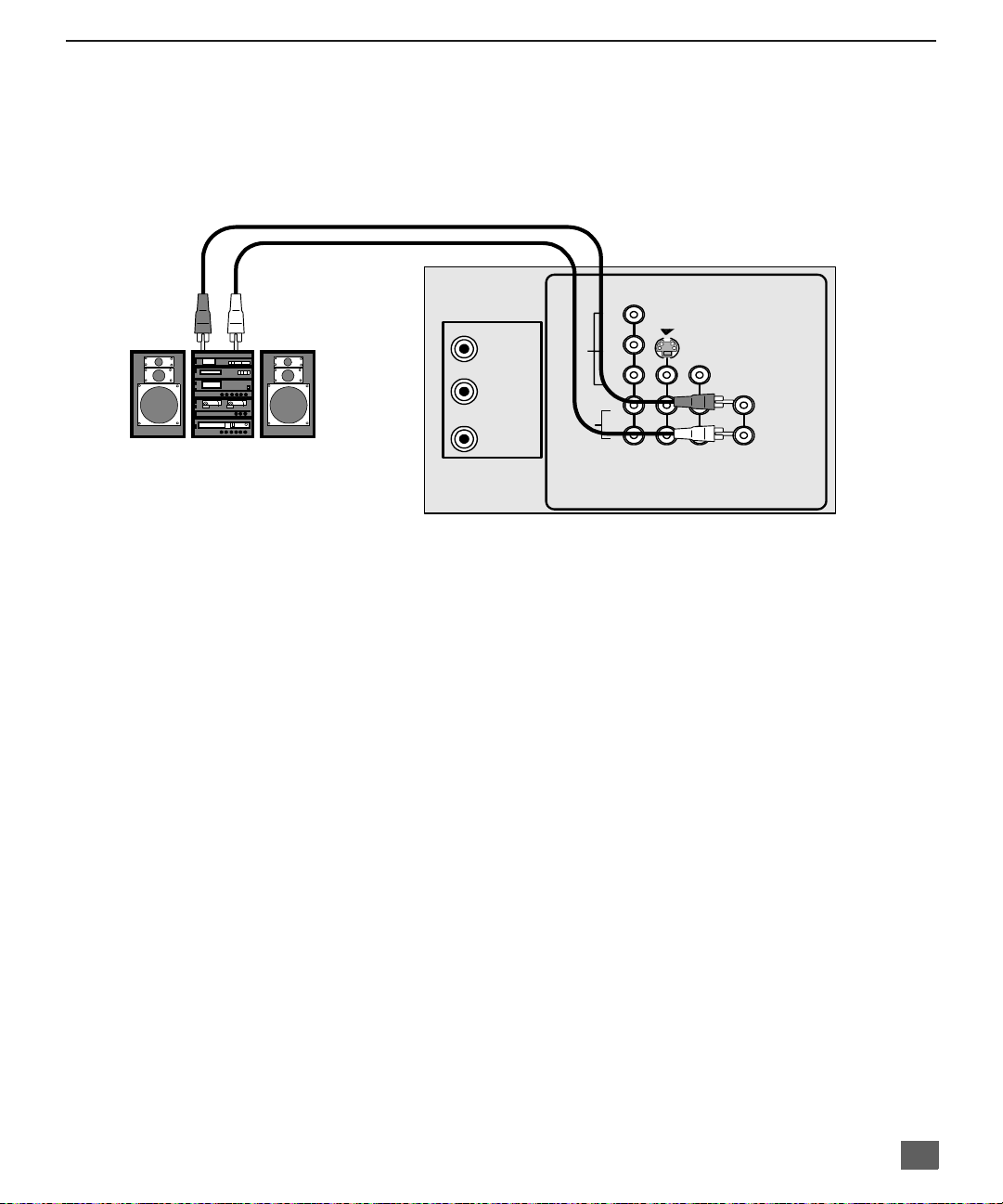
Amplifier Connection (TO AUDIO AMP)
To listen through a sep arate s tereo s ystem, c onnec t an exter nal audio amplifie r T O AUDIO AMP
inputs on back of television.
Note: TO AUDIO AMP terminals ca nno t be co nne cted directly to external speakers.
I
CONNECTIONS ON BACK OF TV (may vary)
NSTALLATION
CABLES NOT SUPPLIED
AMPLIFIER
Audio Adjustments Procedure
1. Select SPEAKERS ON located in the on screen AUDIO menu .
2. Set amplifier volume to minimum.
3. Adjust TV volume to desired level.
4. Adjust amplifier volume to match the TV.
5. Select SPEAKERS OFF & VARIABLE AUDIO OUT from AUDIO menu to
control speakers from the TV or select FIXED AUDIO OUT to control
speakers from the external amplifier.
6. Volume, mute, bass, treble and balance are now controlled from the TV, if you
select VARIABLE AUDIO OUT mode.
ANT 1
SPLIT
OUT
ANT 2
VIDEO
AUDIO
COMPONENT
VIDEO INPUT
Y
INPUT
1
S-VIDEO
INPUT
2
VIDEO
TO AUDIO
AMP
P
B
P
R
L
R
9
I
NSTALLATION
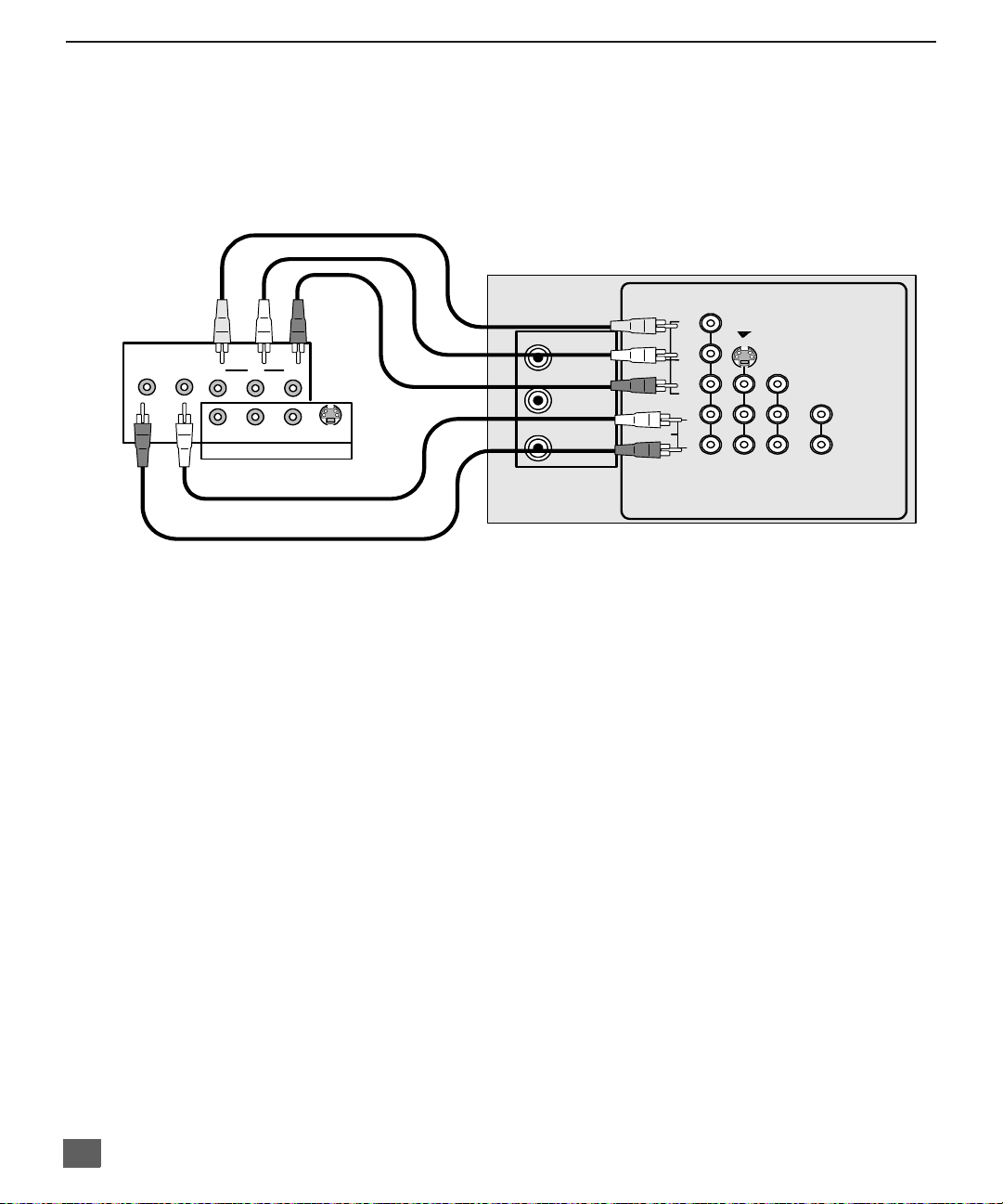
Digital TV - Set-Top Box (DTV-STB) Connection or DVD Player Connection
(some models)
Use this diagram to connec t the Panasonic DTV-STB (Digital TV-Set-Top Box) to the
back of your TV. Press the TV/VIDEO button to select Component mode.
TERMINAL ON BACK OF DTV-STB OR DVD PLAYERS
Y
INPUT
1
S-VIDEO
INPUT
2
VIDEO
TO AUDIO
R-AUDIO-L
P
Y
R-AUDIO-L VIDEO
P
R
B
NTSC OUTPUT
DIGITAL OUTPUT
S-
VIDEO
CABLES NOT SUPPLIED
AUDIO
COMPONENT
VIDEO INPUT
P
B
P
R
L
R
ANT 1
SPLIT
OUT
ANT 2
VIDEO
COMPONENT VIDEO INPUT ON BACK OF TV
AMP
10
Notes:
r There are three video inputs, Y, PB, and PR. Separate com ponent color inputs pro vide
luminance and color separation. Use the L (left) and R (right) audio inputs.
r Select DTV-STB to 480i output mode. TV set can receive 480i signal only.
Picture In Picture (PIP) Operation
This television includes a two tuner Picture In Picture (PIP) feature. This allows
watching two (2) live broadcasts at the same tim e without or with an exte rnal video
source (VCR).
Basic PIP Operation
Procedure
Press the PIP button on the remote control to display the
Note: The audio is for the Main Picture only.
1. Choose channels for the
up/down buttons.
2. Choose channels for the
buttons or by using the numeric keypad.
PIP Operation with a Cable Box
Procedure
r To view premium (scrambled) cable channels through your cable box in the
Note: Use this procedure if you want to watch premium cable channels in the Main Picture
while viewing a television program or video in the PIP frame.
1. Select ANT2 in the SET UP menu under Prog Chan (Program C hannels).
2. Tune television to Channel 3.
3. Press the PIP button on the remote control to display the
Note: The audio is for the Main Picture only.
4. Verify the cable box is ON.
5. Choose channels for the
6. Choose channels for the
and using the PIP CHANNEL up/down buttons.
PIP
frame on screen.
PIP
frame by pressing the remote control PIP CHANNEL
Main Picture
by pressing the remote control CH up/down
SWAP Button
The SWAP button switches the PIP and Main
Picture source. Press the RECALL button for on
screen PIP and Main Picture source status.
PIP
Main Picture
PIP frame
by tuning the cable box.
by pressing the TV button on the remote control
I
NSTALLATION
Main Picture
frame on screen.
:
Note: Swap is not available when using the cabl e box to tun e channe ls. If your cab le box ha s
a video output, it can be connected to the television to allow you to use all PIP
functions. See the equipment manual for more information. (Tune the PIP to the video
input connected to the cable box).
11
R
OLLER GUIDE MENU NAVIGATION
Roller Guide Menu Navigation
ROLLER GUIDE MENU SELECTIONS
Procedure
1. Press the ACTION button on the Remote Control to display the Roller Guide Menu.
2. Press the CH up/down to rotate the Roller Guide to the desired feature.
3. Press the ACTION button to display main menus and submenus.
4. Press the CH up/down buttons to highlight desired main menu feature.
5. Press the VOL right button to enter submenus.
6. Press the CH up/down buttons to highlight desired submenu feature.
7. Press the VOL right/left button to select or adjust feature.
8. Press the ACTION button twice to return to the Roller Guide Menu.
9. To exit the Roller Guide Menu, press the VOL left button.
Remote ACTION / Navigation Button
CH
Remote Control Guide
The Re mote Control Quick Reference Guide is located within the package provided
with this TV.
12
VOL
VOL
CH
R
OLLER GUIDE FEATURE CHART
Roller Guide Feature Chart
M
ENU
D
ESCRIPTION
SET UP
LANGUAGES
PROG. CHAN
(Program Channels)
CC
(Closed Captioning)
OTHER ADJ.
r Select English, Spanish, or French menu.
r MODE - Select Cable or TV. See
Installation section in manual.
r ANTENNA - Select ANT 1 or ANT 2
(some models).
r AUTO PROGRAM - Automatically program
channels having a signal into memory.
r MANUAL PROGRAM - Manually add or
delete channels from memory.
r CC ON MUTE - Activate C1-C4 for Closed
Captioning display when the remote MUTE
button is p ressed.
r CC MODE - Select T1-T4 or C1-C4 for
Closed Captioning, program guides and
other information.
r AUTO POWER ON - Select SET to power
up the PTV at the same time as the Cable
Box or other components or select OFF.
r CONVERGENCE 1 - Adjustment may be
required w hen the PTV i s moved bec ause
of the effects of the Earth’s magnetic field
on the projection tubes.
r CONVERGENCE 2 - Adjustment may be
required after setting Convegence 1.
AUDIO ADJ.
(Adjustments)
AUDIO
r MODE - Select STEREO, SAP (Second
Audio Program) or MONO. (Use MONO
when stereo signal is weak.)
r BASS - Increase or decrease the bass
response.
r TREBLE - Increase or decrease the treble
response.
r BALANCE - Emphasize the left/right
speaker volume.
r NORMAL - Reset BASS, TREBLE and
BALANCE to factory default.
13
R
OLLER GUIDE FEATURE CHART
Roller Guide Feature Chart (Cont.)
M
ENU
OTHER ADJ.
(Adjustments)
SURROUND
SPEAKERS
CLOCK SET
SLEEP
TIMER 1
TIMER 2
r AI SOUND - Automatically adjust volume
to maintain a comfortable listening level.
(AI sound is not available in VIDEO mode).
r BBE - Sound technology enhances speech
intelligibility and restores the dynamic
range of musical passages to provide
outstanding natural sound.
r SURROUND - Enhances audio response
when listening to stereo.
r ON - TV speakers operate normally.
r OFF & VAO (Variable Audio Output) -
TV speakers off - audio adjustable by TV.
r OFF & FAO (Fixed Audio Output)-
TV speakers off — audio adjustable only
by the external amplifier.
r Set the time and the day of the week.
(Time will dis play on scree n after turning on
the television, pressing the RECALL button
or changing channels).
r Set timer to turn off TV in 30, 60 or
90 minutes. Select NO to turn timer off.
r Set one or both timers to automatically turn
television on and off at selected times, on
selected c hannels, and on selected days.
(Clock must be set to use Timer features).
D
ESCRIPTION
TIMER
14
 Loading...