

Panasonic PT- 65WX51E, PT- 56WX51E, PT- 56WX51CE Service Manual
ORDER NO. MTNC010631A1
B2
Service Manual
HDTV MONITOR
Simplified Manual
Simp
lifie d
P5PW
Panasonic
Models
PT- 65WX51E EP820
PT- 56WX51E EP820
PT- 56WX51CE EP820
Chassis
PT-65WX51E
This Simplified Service Manual is issued to add listed models to the Simplified Service Manual order No.
MTNC010522A1 (PT-47WX51E). Incl ud ed in this ma nual are schematics that are un iq ue to the listed models, unique
disassembly proce dures, and a c omplete parts list for th e serviceable boards are included i n this Simpl ified Manua l.
Please file and use this manual together with Simplified Service Manual, order No. MTNC010522A1 (PT-47WX51E).
“WARNING! This Service Man ual is desig ned for expe rienced repa ir technici ans only and is not designed f or use by t he general p ublic.
It does not contain warnings or cautions to advise non-technical individuals of potential dangers in attempting to service a product.
Products powered by electricity should be serviced or repaired onl y by experienced pro fessional technicians. Any attempt to
service or repair the product or products dealt with in this Service Manual by anyone else could result in serious injury or death.”
The service technician is required to read and follow the “Safety Precautions” and “Important Safety Notice” in this Manual.
Copyright 2001 by Matsushita Electric Corporation of
America. All rights reserved. Unauthorized copying
and distribution is a violation of law.
Important Safety Notice
Special components are used in this projection television that are important for safety. These components are
identified on the schematic diagram by the symbol and printed in BOLD TYPE on the replacement part list. It is
essential that these criti cal parts be repla ced with the manufactur er’s specifie d replacement part to pre vent x-ray
radiation, shock, fire or other hazards. Do not modify the original design without the manufacturer’s permission.
Safety Precautions
General Guidelines
An
isolation transformer
during the servicing of a PTV whose chassis is not
isolated from AC power line. Use a transformer of
adequate power rating a s this protects the techn ician
from accidents resulting in personal injury from
electrical shocks. It will also p rotect the PTV from being
damaged by accidental shorting that may occur
during servicing.
When servicing, observe the original lead dress,
especially in the high voltage circuit. Replace all
damaged parts (also parts that show signs of
overheating.)
Always replace protective devices, such as
fishpaper, isolation resistors and capacitors, and
shields after servicing the PTV. Use only
manufacturer ’s recommended ra ting for fuses, c ircuits’
breakers, etc.
High potentials, as high as 32kV, are present when this
PTV is operating. Operation of the PTV without the rear
cover introduces danger for elect rical shock. S ervicing
should not be performed by anyone who is not
thoroughly familiar with the necessary precautions
when servicing high-voltage equipment.
Extreme care should be pr acticed when handling the
picture tube
due to atmospheric pressure. (14.7 lbs. per sq. in.). Do
not nick or scratch the glass or subject it to any undu e
pressure. When handling, use safety goggles and
heavy gloves for protection. Discharge the picture
tube by shorting the anode to chassis ground (not to
the cabinet or to other mounting hardware). When
discharging, connect cold ground (i.e. DAG ground
lead) to the a node with a well-insulated wire or use a
grounding probe.
. Rough handling may caus e it to implod e
should always be used
X-ray Precautions
The front area (between the projection tube and the
lens) is enclosed by a metal box to ensure positive
safety during normal and abnormal conditions when
checking and repairing. To fully ensure safety, the
following precautions must be observed.
1. Do not remove the lens or metal box.
2. Make sure to turn the power OFF when the le ns is
removed or when checkin g the cleanliness of the
lens.
3. Do not remove the lens or metal box to check the
projection tube for operation by w atching it directly.
Use a mirror or paper to view the image.
Before returning a se rviced PTV to the owner, the
service technician must thoroughly test the unit to
ensure that is completely safe to operate. Do not use a
line isolation transformer when testing.
Leakage Current Cold Check
Unplug the AC cord and connect a jumper between the
two plug prongs. Press the POW ER swit ch ON.
Measure the resistance between the jumpered AC plug
and expose metallic parts such as screw heads,
Service Manual
antenna terminals, control shafts, etc. If the exposed
metallic part has a return path to the chassis, the
reading should be between 240k
exposed metall ic part does not have a re turn path to
the chassis, the re adi ng sh oul d be infinite.
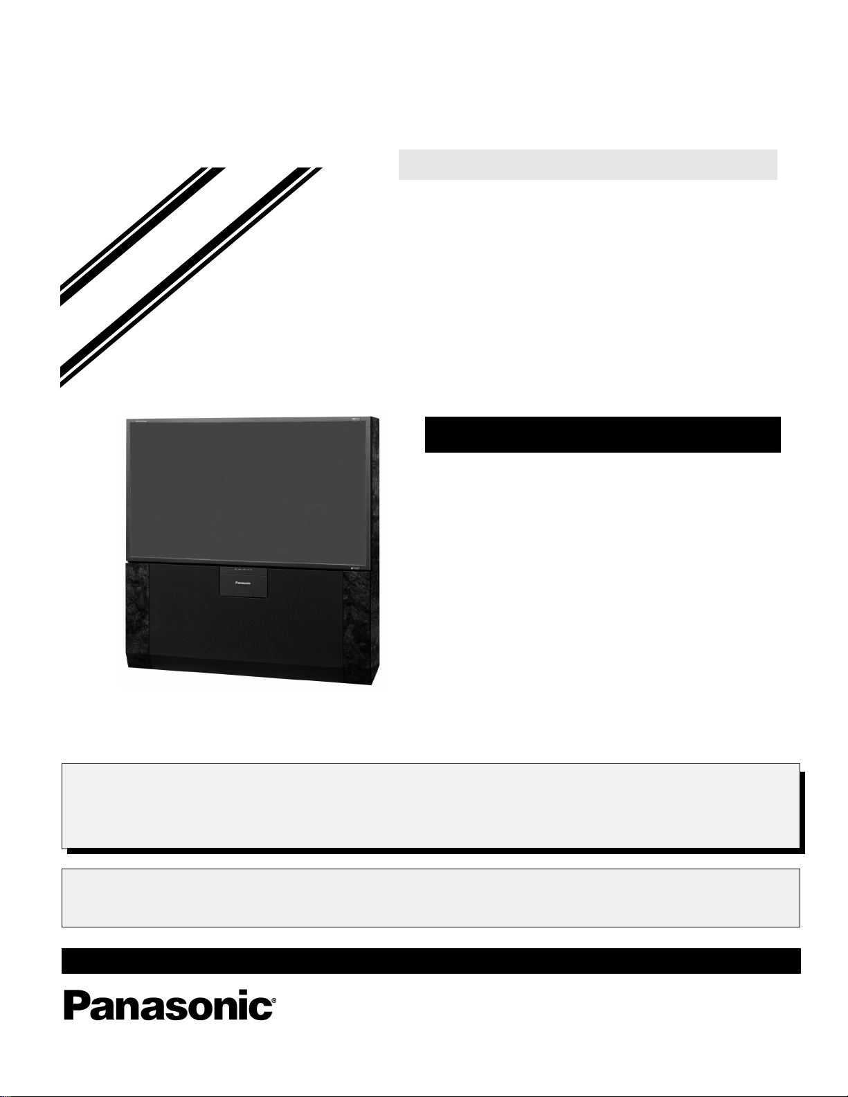
Leakage Current Hot Check
Plug the AC cord directly into the AC outlet. Do not use
an isolation transformer during the check.
Connect a 1.5k
0.15mF capacitor between and exposed metallic part
and ground. Use earth ground, for example a water
pipe.
Using a DVM with a 1000 ohms/volt sensitivity or
higher, measure the AC potential across the resistor.
Repeat the procedure and measure the voltage
present with all other expose metallic parts.
Verify any potential does not exceed 0.75 vo lt RMS. A
leakage current tester (such a Simpson Model 229,
Sencore Model PR57 or equivalent) may be used in
the above procedure, in which case any current
measure must not exceed 0.5 milliamp. If any
measurement is out of the specified limits, there is a
possibility of a shock hazard and the PTV must be
repaired and rechecked before it is returned to the
customer.
10-watt resistor in parallel with a
Ω
Figure 1. Hot Check Circuit
and 5.2MΩ. If the
Ω
(See Fig. 1)
Insulation Test
Connect an insulation tester between an exposed
metallic part and AC line.
Apply 1080VAC/60Hz for 1 second. Confirm that the
current measurement is 0.5mA ~ 2.0mA. Repeat test
with other metallic exposed parts.
X-ray Radiation
WARNING: The potential source of X-ray radiation in the
PTV is in the high voltage section and the picture tube.
Note: It is important to use calibrated equipment.
Apply all black video signals (1080i) and confirm high
voltage measures 31.5 ± 1.0kV. If the high voltage is
not within the range, c hange C51 4 to 1800p F, 2000pF,
2400pF or 2700pF until the desired value is obtained.
Apply NTSC Lion Head Pattern and confirm the high
voltage measures 3 0.1 ± 1.5kV.
Apply HD 1081I Monoscope Pattern and confirm the
high voltage measures 30.1 ± 1.5kV
- 2 -
Important Safety Tests
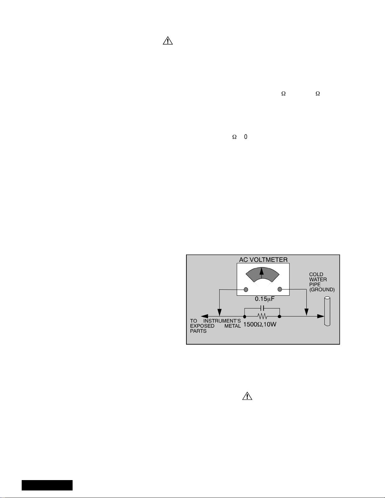
Measuring H.V.
The anode caps are cemented to the CRTs. To gain
access for high vo ltage measurem ent, remove the re d
CRT’s anode lead from the flyback transformer
distributor. Grasp the anode lead protective cap at its
bottom and squeeze it against the locking cap body
inside, Rotate 1/4 turn count er clockwise and pull the
anode lead sleeve out of the FBT distributor. Connect a
high voltage lead (+) from your H.V. meter to the FBT
distributor, and the common (-) to cold ground ( ).
(See Fig. 2).
1
Grasp protective
Anode lead
rubber cap
3
2
Push & rotate
Discharge to
CRT Chassis
cap counterclockwise
to remove
FBT Distributor
Figure 2. Removal of FBT leads
Note: Reinsert the anode lead into the FBT
distributor until it is tightly and fully seated.
T urn the locking cap clockwise to lock in place.
(EHT) Protector Operation Check
With the cabinet ba ck removed, apply a n ominal 120V
AC to the PTV.
Over Voltage Test
Preparation:
1. Turn PTV “OFF”
2. Connect an NTSC signal generator to the
antenna terminal.
3. Connect DVM (+) TPD50 and (-) TPD51 on
D Board. (See Fig. 4)
4. Connect a H.V. meter (static type, class 0.1 ) with
high voltage leads to high voltage distributor
on FBT. (See Fig. 4)
TPD51 TPD50
-
+
D-Board
DVM
D-Board
IC802 PIN 2
OR TPD8
Variable
Power
Supply
MA150
100Ω 1/2 W
(+)
(15~25DC)
(-)
HEAT SINK OF Q551
Figure 4. DVM & Power supply connection.
Connect the 15 ~ 25 V DC variable power supply to (+)
TPD8 or IC802 pin 2 (D-Board) and (-) heat sink of
Q551 (See Fig. 4).
Procedures:
1. Apply a monoscope pattern.
2. Turn PTV ON.
3. Adjust the Picture or Brightness controls so that the
DVM reads 12.4 volts ± 0.4 volts.
4. Increase the variabl e power supply until set turns
off. The set should turn off at 12.4 volts ± 0.4 volts
(DVM) and high voltage le ss th an 3 6.4k V.
5. If the DVM reading is other than 12.4 volts (± 0.4
volts), readjust picture or brightness control and
repeat steps 3.
6. Turn off the variable supply and confirm that the set
will turn on with the Remote Control.
-
+
H.V. METER
Cold Ground
FBT Distributor
CRT
CHASSIS
Figure 3. Measuring H.V.
- 3 -
Service Manual

Important Safety Notice. . . . . . . . . . . . . . . . . . . 2
Safety Precautions . . . . . . . . . . . . . . . . . 2
General Guidelines . . . . . . . . . . . . . . . . . 2
X-ray Precautions . . . . . . . . . . . . . . . . . . 2
Leakage Current Cold Check . . . . . . . . . 2
Leakage Current Hot Check . . . . . . . . . . 2
Insulation Test . . . . . . . . . . . . . . . . . . . . . 2
X-ray Radiation . . . . . . . . . . . . . . . . . . . . 2
Important Safety Tests. . . . . . . . . . . . . . . . . . . . 3
Measuring H.V. . . . . . . . . . . . . . . . . . . . . 3
(EHT) Protector Operation Check . . . . . . 3
Leadless Chip Component
(surface mount). . . . . . . . . . . . . . . . . 5
Component Removal. . . . . . . . . . . . . . . . 5
Chip Component Installation . . . . . . . . . . 5
How to Replace Flat-IC . . . . . . . . . . . . . . 5
Feature Table . . . . . . . . . . . . . . . . . . . . . . . . . . . 6
PCBs Designation . . . . . . . . . . . . . . . . . . . . . . . 7
PTV - Location of Controls . . . . . . . . . . . . . . . . 8
Quick Reference Control Operation . . . . 8
Remote - Location of Controls
Basic Operation . . . . . . . . . . . . . . . . . . . . . . 9
Disassembly for Service . . . . . . . . . . . . . . . . . 10
PTV Frame Assembly. . . . . . . . . . . . . . . . . . . . 10
PTV Screens Preparation. . . . . . . . . . . . . . . . . 11
Placement of Screens in PTV
Screen Frame . . . . . . . . . . . . . . . . . . . . . . . 12
Frame and Customer Controls
Panel Installation . . . . . . . . . . . . . . . . . . . . 13
Cabinet Top and Mirror Panel Installation . . . 14
G, K-Board schematics. . . . . . . . . . . . . . . . . . . . 25
G, K-Board PCBs. . . . . . . . . . . . . . . . . . . . . . . .26
Service Manual
- 4 -
Service Notes
Note: Some components may be affixed wit h glue. Be caref ul not to break or dama ge foil under the com ponent
or at the pins of th e ICs when removing . Usually applying heat to the component for a short time while
twisting with tweezers will break the component loose.
Leadless Chip Component
(surface mount)
Chip components must be replaced with identical chips
due to critical foil track sp acing. There are no holes in
the board to mount standard transistors or diodes.
Some chips, capacitor or resistor board solder pads
may have holes thr ough the board, however the hole
diameter limits standard resistor replacement to 1/8
watt. Standard capacitor may also be limited for the
same reason. It is recommended that identical
components be used.
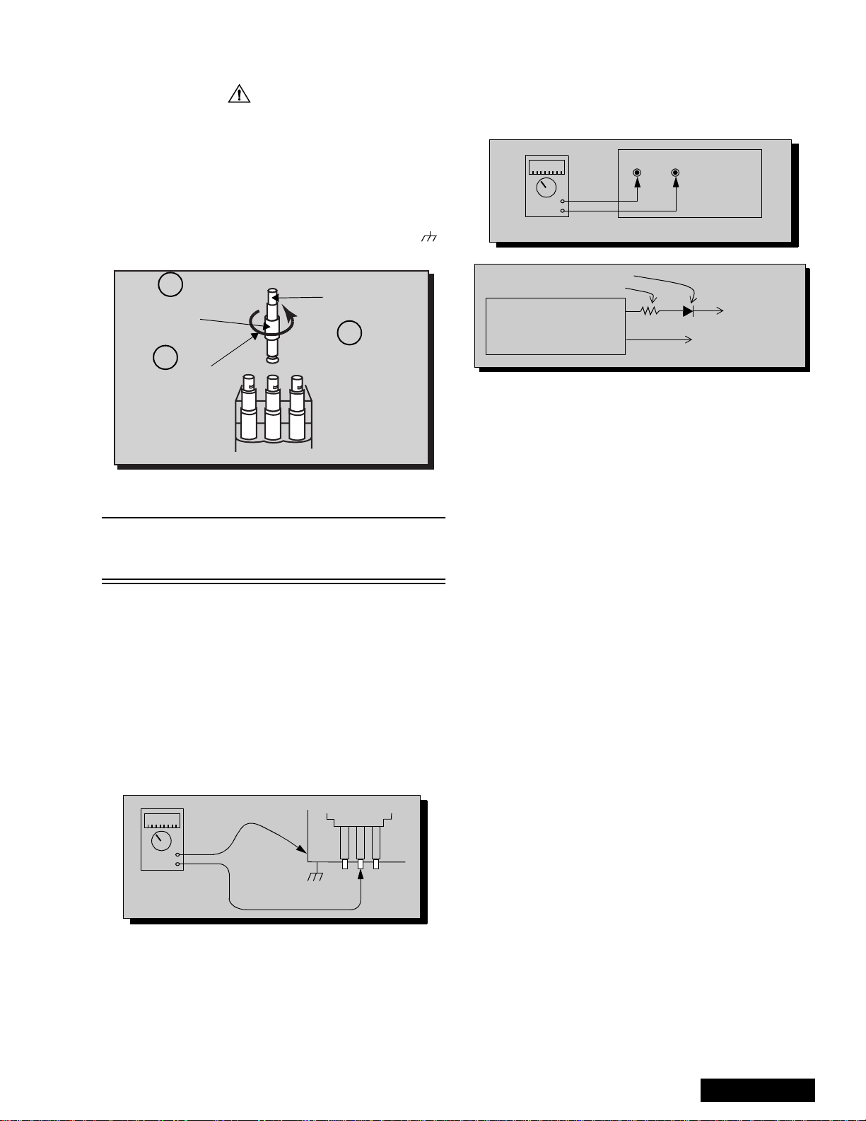
Chip resistors have a three-digit numerical resistance
code - 1st and 2nd significant digits and a multiplier.
Example: 162 = 1600 or 1.6kW resistor, 0 = 0W
(jumper).
Chip capacitors generally do not have the value
indicated on the capacito r. The color of the component
indicates the general range of the capa ci tan ce .
Chip transistors are identified by a two-letter code. The
first letter indicates the type and the second l etter, the
grade of transistor.
Chip diodes have a two-letter identification code as per
the code chart and are a dual diode pack with either
common anode or comm on cathode. Check the parts
list for correct di ode num ber.
Component Removal
7. Use solder wick to remove s older fr om compo nent
end caps or termin al.
8. Without pulling up, carefully twist the component
with tweezers to break the adhesive.
9. Do not reuse removed leadless or chip
components since they are subject to stress
fracture during removal.
Chip Component Installation
1. Put a small amount of solder on the board
soldering pads.
2. Hold the chip component against the soldering
pads with tweezers or with a miniature alligator clip
and apply heat to the pad area wi th a 30 watt iron
until solder flows. Do not appl y heat for more than
3 seconds.
Chip Components
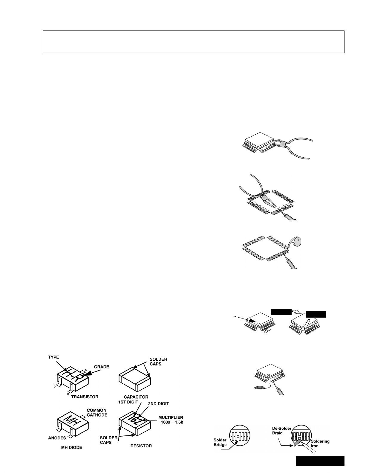
How to Replace Flat-IC
- Required Tools -
• Soldering iron • De-solder braids
• Needle nose pliers • Magnifier
• Wire cutters (sharp & small)
1. Cut the pins of a defective IC with wire cutters.
Remove IC from boar d. If IC i s glued to the boa rd,
heat the IC and release the IC. See Note above.
Flat IC
2. Using soldering iron and needle nose pliers
remove the IC pins from the boa rd .
Soldering
Iron
3. Using de-soldering braid and soldering iron remove
solder from affected are on board (pads).
De-soldering
Braid
Soldering
Iron
4. Position the new Flat-IC in pl ace (apply the pins of
the Flat-IC to the soldering pads where the pins
need to be soldered). Determine the positions of
the soldering pads and pins by correctly aligning
the polarity symbol. Solder pin #1 first, align the IC.
Polarity
symbol
Solder the pin op posite to pin #1. This will assist
positioning the IC.
5. Solder all pins to the soldering pads using a fine
tipped soldering iro n.
2nd solder
1st solder
Solder
6. Check with a magnifier fo r solder bridge between
the pins or for dry joint between pins and soldering
pads. To remove a solde r bridge, use a de-solder
braid as shown in the figure below.
- 5 -
Soldering
Iron
Service Manual
IMPORTANT: To protect against possible damage to
the solid state devices due to arcing or static
discharge, make cer tain that all ground wi res an d CRT
DAG wire are secu re ly conne cted.
CAUTION: The power supply circuit is above earth
ground and the chassis cannot be polarized. Use an
isolation transformer when s ervicing the PTV to avoid
damage to the test equipment or to the chassis.
Connect the test equip ment to the proper ground or
when servicing, or incorrect voltages will be
measured.
WARNING: This PTV has been designed to meet or
exceed applicable safety and X-ray radiation protection
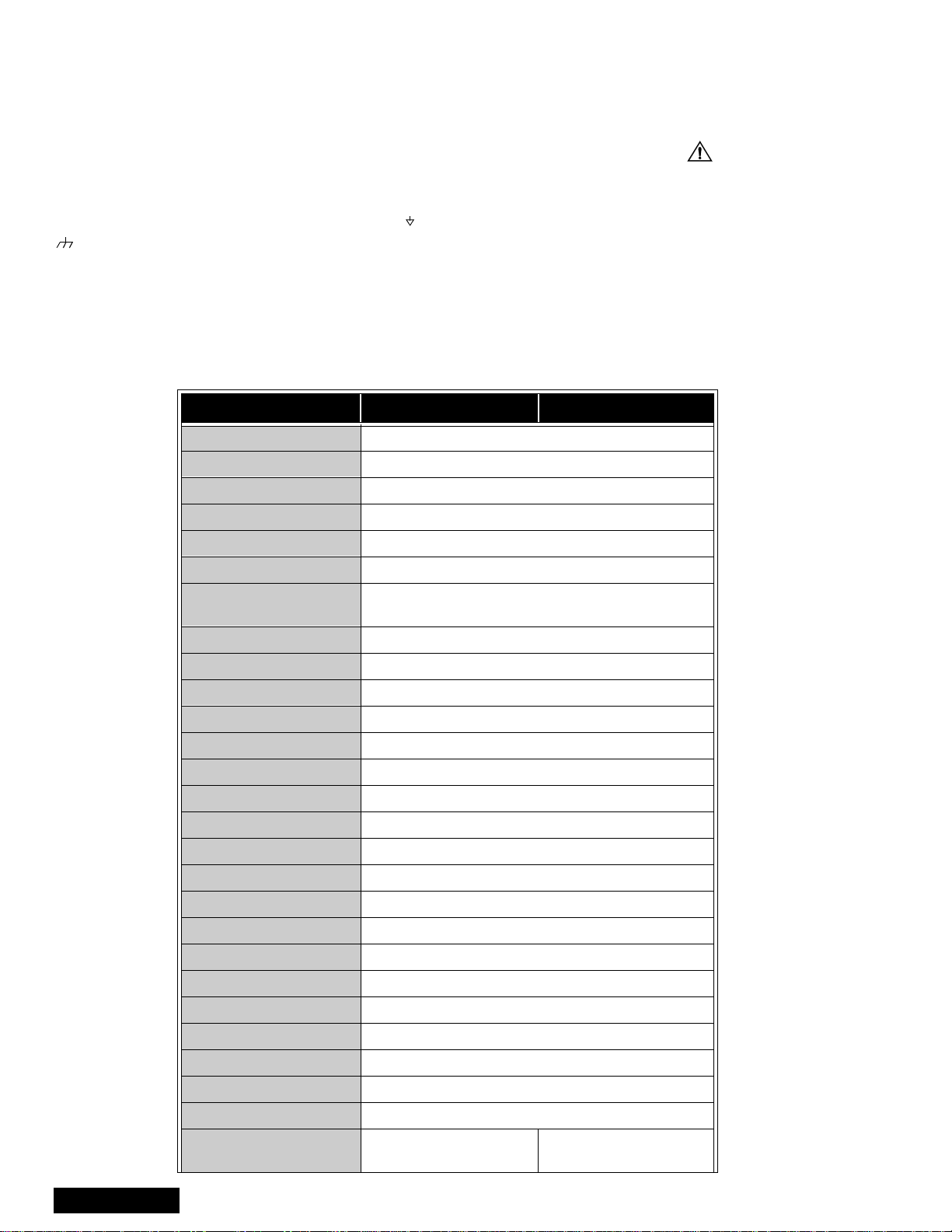
Feature Table
FEA TURE PT-65WX51E PT-56WX51E/CE
Chassis EP820
T uning sy stem 256K
# of channels 181
as specified by gover nment a gencies and ind ependen t
testing laboratories.
To maintain original product safety design standards
relative to X-ray radiation and shock and fire hazard,
parts indicated with th e symbol on the schematic
must be replaced with identical parts. Order parts from
the manufacturer’s parts center using the parts
numbers listed in this service manual, or provide the
chassis number and the part reference number.
For optimum performance and readability, all other
parts should be rep laced with component s of identical
specification.
Menu language Eng/Span/Fr
Closed Caption X
V-Chip (USA/CANADA) X
Picture in Picture
2RF X
Comb Filter 3D Y/C
HEC / VEC Corrector Both
VM X
V/A Norm - Both Both
Color Temperature X
MTS/SAP/DBX X
AI Sound X
Bass/Bl/T re Contro l X
Surround X
BBE X
Built-in audio power 15W / CH (10%)
# of speakers 4
2 Tuner
Split Screen
Service Manual
A/V in (rear/front) 4 (3 / 1)
A/V Program Out X
S-VHS Input (rear/front) 2 / 1
Component Input 2
Audio Out (FAO & VAO) X
Dolby Center Channel In X
Dimensions mm
(WxDxH) in
1501x757x1545
59.1x29.8x60.8
- 6 -
1316x682x1401
51.8x26.9x55.2
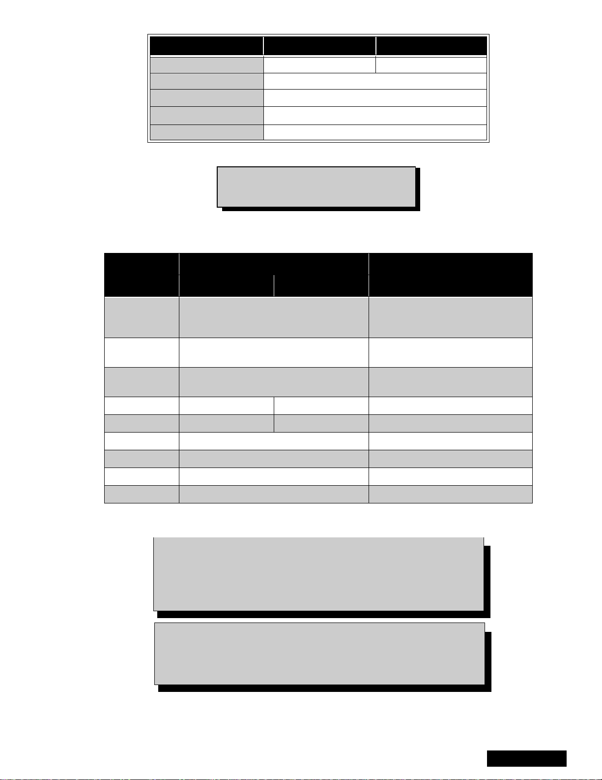
FEATURE PT-65WX51E PT-56WX51E/CE
Weight (kg/lbs) 126.5/277.78 116/255.7
Power source (V/Hz) 120 / 60
Anode voltage 31.5 ± 1.0kV
Video input jack
Audio input jack 500mV RMS 47kΩ
Table 1: PTV Feature Table
Specifications are subject to change
without notice or obligation.
Dimensions and weights are approximate.
PCBs Designation
PART NUMBER
BOARD
PT-56WX51E/CE PT-65WX51E
A-Board TNPH0370AD
75Ω, phono jack
1V
p-p
BOARD DESCRIPTION
MAIN CHASSIS, VIDEO
PROCESSING, CONVERGENCE,
AUDIO PROCESSING
D-Board TNPH0371
DH-Board TNPA2033
POWER SUPPLY, VERTICAL
OUT, HORIZONTAL OUT
PIP PROCES SING , SPLIT,
SEARCH, FORMATS
G-Board TNP2AA090 TNP2AA092 Front A/V Connections
K-Board TNP2AA089 TNP2AA091 Customer Controls (Key board)
LR-Board TNPA1810 RED CRT Drive
LG-Board TNPA1811 GREEN CRT Drive
LB-Board T NPA1812 BLUE CRT Drive
R-Board TNPA0615AB IR Sensor
Table 2: PCB Des i gna tion
Note: The A-Board (
TNPH0370ADS
) and DH-Board (
TNPA2033S)
are Non-Serviceable. The Tuners, IC2302, IC7001, IC7002 and
IC870 are replaceable. If any other components on the A-Board
or DH-Board are defective, replace the en tire board with a new
one.
Notice: When ordering any Board, add and” S” after the Board suffix
application for all models.
Example: If Order A-Board, should be ordered as:
TNPH0370AD
S.
- 7 -
Service Manual
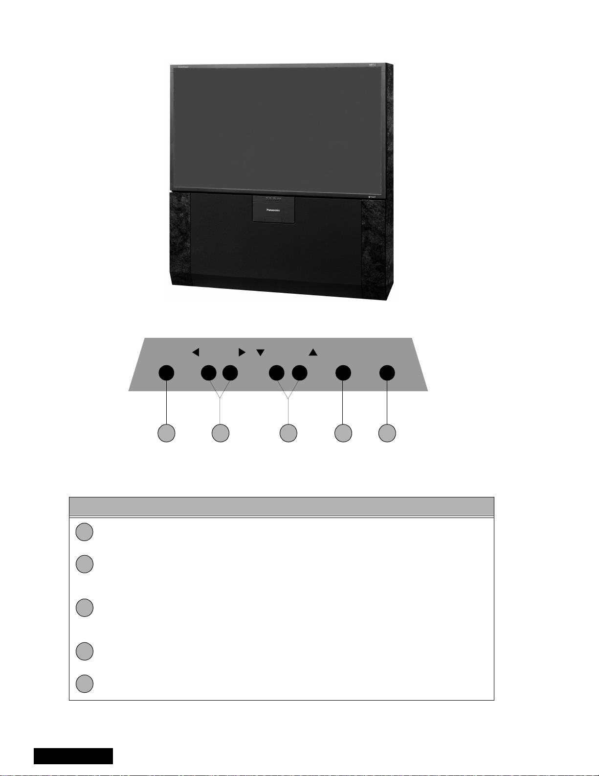
PTV - Location of Controls
PT-65WX51E
POWER VOLUME CHANNEL ACTION TV/VIDEO
1 2 4 53
Figure 5. Location of Control s PTV
Quick Reference Control Operation
Quick Reference Control Operation
1
2
3
Power - Press to turn ON or OFF.
Volume - Press to adjust Sound Level, or to adjust Audio Men us, Video Menus, and
select operating features when menus are displayed.
Channel - Press to s elect programm ed channels. Pres s to highlight desired features
when menus are displayed. Also use to select Cable Converter box channels after
programming Remote Control Infra red codes ( the TV/AUX /CABLE sw itch must be s et
in CABLE position).
4
5
Service Manual
Action - Press to displ ay Main Menu and access On Screen f eature and Ad justment
Menus.
TV/Video - Press to select TV or one of two Video Inputs, for the Main Picture or the
PIP frame (when PIP frame is displayed).
- 8 -
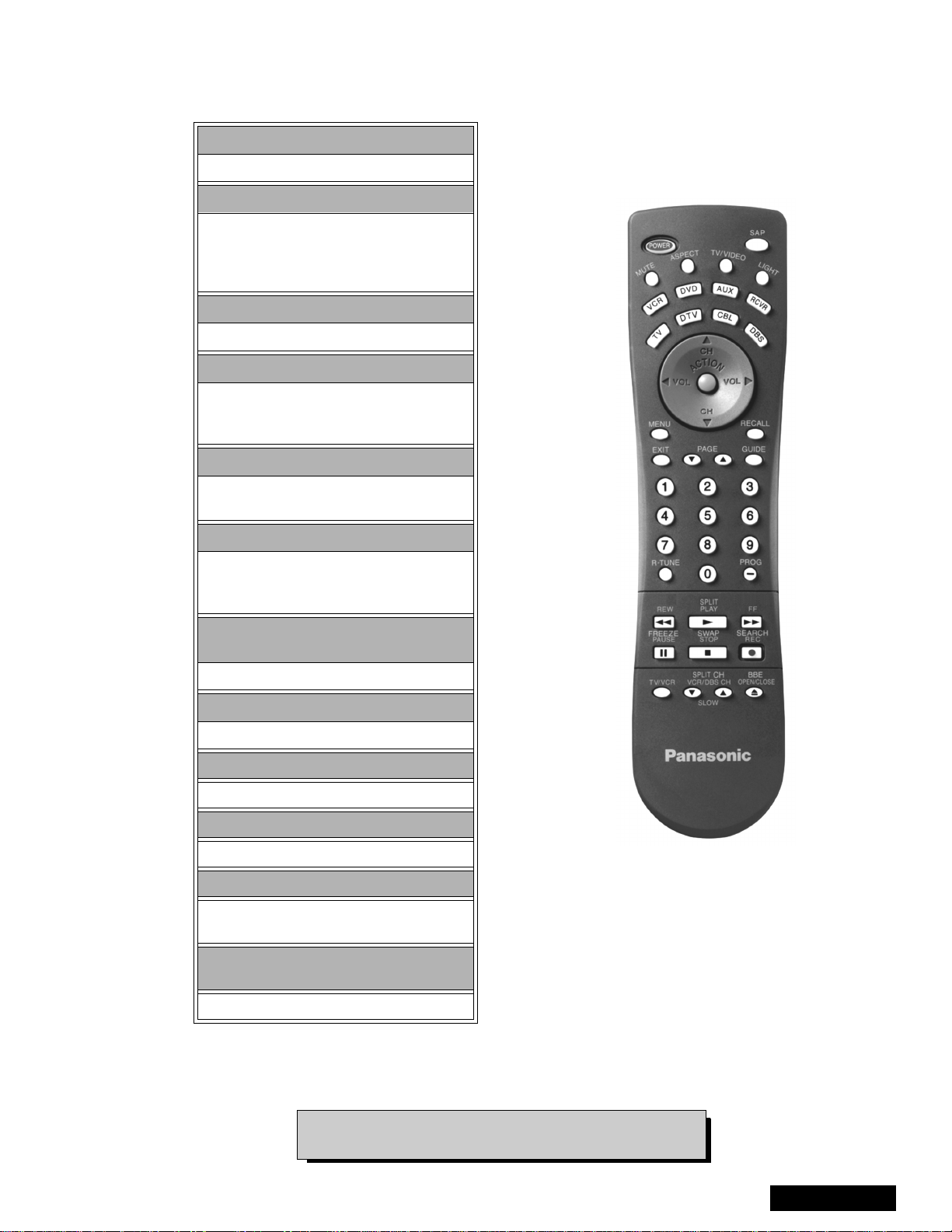
Remote - Location of Controls-Basic Operation
POWER Button
Press to turn ON and OFF.
MUTE Button
Press to mute sound.
A second press resumes sound.
Press also to access and delete
Closed Caption display.
TV, VCR, DVD, CBS/CBL
Component function buttons
VOL (volume) Buttons
Press to adjust TV sound level.
Use with Channel buttons to
navigate in menus.
R-TUNE (Rapid Tune) Button.
Press to switch to the previous
channel.
ACTION Button
Press to display Main Men u and access or
exit On Screen features
and Adjustment Menus.
REW, PLAY, FF, TV/VCR, STOP, PAUSE,
REC & VCR CHANNEL Buttons
Component function buttons.
DBS EXIT& DBS GUIDE Buttons
DBS function buttons.
LIGHT Button
Press to light remote control buttons.
SAP
Access second audio program
ASPECT
Select picture size (ratio) to match
programming format
MOVE, PIP, SPLIT/SIZE, FREEZE, SWAP,
SEARCH, PIP CHANNEL
EUR7603Z40
PIP function buttons
For additional information for this rem ote please refer
to the Remote Guide, listed on the parts li st.
Figure 6. Location of Controls
- 9 -
Service Manual
 Loading...