

Panasonic PT-51HX40, PT-61HX40, PT51HX40B - 51"" PROJECTION TV, PT56HX40B - DIGITAL PTV MONITOR, PT61HX40B - 61"" PROJECTION TV Operating Instructions Manual

Color Video Projection System
Operating Instructions
PT-51HX40 PT-61HX40 PT-56HX40
®
TQB2AA0342 00407
PRINTED IN USA
B0342E Production.fm Page 1 Wednesday, February 7, 2001 11:10 AM
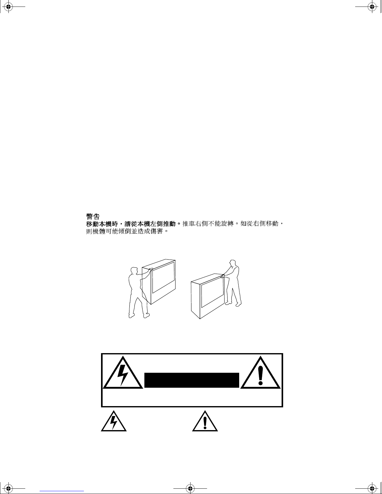
:$51,1*
7R PRYH VHW SXVK IURP OHIW VLGH RI VHW
GR QRW SLYRW LQ DOO GLUHFWLRQV 6HW FDQ WLS RYHU LI PRYHG IURP
ULJKW VLGH ZLWK ULVN RI SHUVRQDO LQMXU\
$'9(57(1&,$
3DUD PRYHU HO FRQMXQWR HPSXMH GHVGH HO ODGR L]TXLHUGR GHO
PLVPR
/RV URODQDV GH OD GHUHFKD QR VRQ SLYRWDQWHV HQ WRGDV
ODV GLUHFFLRQHV (O FRQMXQWR VH SXHGH WXPEDU VL VH OR PXHYH
GHVGH HO ODGR GHUHFKR FRUULHQGR DVt HO ULHVJR GH VXIULU GDxRV
SHUVRQDOHV
0LVH HQ JDUGH
/RUV GX GpSODFHPHQW GX WpOpYL VHXU OH SRXVHU VXU VRQ F{Wp
JDXFKH
WRXWHV OHV GLUHFWLRQV O·DSSDUHLO SRXUUDLW WRPEHU V·LO HVW SRXVVp
GH FH F{Wp HW FDXVHU DLQVL GHV ULVTXHV GH EOHVVXUH
/HV URXOHWWHV GX F{Wp GURLW QH SRXYDQW WRXUQHU GDQV
&DVWHUV RQ ULJKW VLGH
Certain audio features of this product manufacture under a license from Desper Products, Inc.
Spatializer® and the circle-in-square device and trademarks owned by Desper Products, Inc.
Spatializer U.S. Patents are: 4,308,423; 4,355,203 and 5,412,731.
WA RNI N G: To reduce the risk of electric shock do not remove cover or back.
No user-serviceable parts inside. Refer servicing to qualified service personnel.
WARNING: To prevent fire or shock hazard, do not expose this appliance
WARNING
RISK OF ELECTRIC SHOCK
DO NOT OPEN
The lightning flash with arrow
head within a triangle is
intended to tell the user that
parts inside the product are a
risk of electric shock to persons.
to rain or moisture.
The exclamation point within a
triangle is intended to tell the
user that important operating
and servicing instructions are i n
the papers with the appliance.

B0342E Production.fm Page 2 Wednesday, February 7, 2001 11:10 AM
T
ABLE OF CONTENTS
T able of Contents
Congratulations........................ ..... ..... .... ..... ..... .... ....3
Customer Record ........................ ....... ...... ....... ...... ...... .............3
Care and Cleaning ...................................................................3
Specifications ...........................................................................3
Installation.................................................................4
Television Location...................................................................4
Optional Cable Connections.....................................................4
AC Power Supply Cord ............................................................4
Cable / Antenna........................................................................4
Optional Equipment Connections.............................................5
VCR Connection.......................................................................5
Cable Box Connection..............................................................6
VCR and Cable Box Connection..............................................7
Amplifier Connection (To Audio Amp) .....................................8
Program Out Connection (Prog.Out)........................................8
Dolby Center Channel Input Connection..................................9
Picture In Picture (PIP) Operation.........................10
Basic PIP Operation..............................................................10
PIP Operation with a Cable Box............................................10
Digital TV - Set-Top (DTV-STB) or DVD
Connection..............................................................11
Roller Guide Menu™Navigation............................12
Basic Navigation.....................................................................12
Remote Control Guide............................................................12
Roller Guide Feature Chart....................................13
Special Features.....................................................16
Program Channels .................................................................16
Closed Captioning..................................................................16
Closed Captioning Mode........................................................16
Closed Caption on Mute.........................................................17
Convergence..........................................................................17
Sleep Timer.............. ...... ....... ...... ...........................................19
Timer 1 and 2 .........................................................................19
Picture....................................................................................20
Audio......................................................................................20
Channels - Favorites ..............................................................21
Channels - Caption.................................................................21
Lock ......................... ....................................... .......................22
Troubleshooting Chart...........................................23
Read these instructions completely before operating PTV.
Contents are subject to change without notice or obligation.
Copyright 2000 by Matsushita Electric Corporation of America. All rights reserved.
Unauthorized copying and distribution is a violation of law.
2

B0342E Production.fm Page 3 Wednesday, February 7, 2001 11:10 AM
Congratulations
Your new Projection Television (PTV) features state-of-the-art technology for high
quality picture and sound with complete audio/video connections for your home
theater system. Your PTV is designed to give you many years of enjoy ment. It was
thoroughly tested and tuned at the factory for best performance.
Customer Record
The model and serial number of this product are located on the back of the PTV. You
should note the model and serial number in the space provided and retain as a permanent
record of your purchase. This will aid in identification in the event of theft or loss. Product
registraton for U.S. customers is available at: www.prodreg.com/panasonic.
Model
Number
Serial
Number
Care and Cleaning
Projection Screen (Turn PTV Off)
C
ONGRATULATIONS
Specifications
The projection s creen is a hi gh precisio n lens syste m which has a p rotective sc reen.
The protective screen is fully washable with the following precautions:
r Use a mild soap solution or window cleaner and a clean cloth.
• DO NOT USE ABRASIVE CLEANERS.
• Do not use laundry detergent or automatic dishwasher soap.
• Do not use alcohol, ammonia, or petroleum based products.
r Avoid excessive moisture and wipe dry.
• Prevent solution from running into the receiver below.
r Avoid bumping or scraping the screen.
Cabinet and Remote Control
r For cabinets and rem ote control, use a sof t cloth dampen ed with water or a mild
detergent solution. Avoid excessive moisture and wipe dry.
r Do not use benzene, thinner or other petroleum based products.
Power Source
PT-51HX40 (3.6A)
PT-56HX40 (3.6A)
PT-61HX40 (3.6A)
Channel Capability - 181 VHF-12; UHF-56; Cable-125
4 Video Input Jacks 1Vp-p, 75 Ohm, Phono Jack Type
8 Audio Input Jacks 500mV RMS 47K Ohm
Video Output Jack 1Vp-p, 75 Ohm, Phono Jack Type
2 Audio Output Jacks 0-2.0V RMS 4.7K Ohm
Component Input (Y / PB / PR)
3 S-Video Input Jacks S-Video (Y-C) Connector
120V AC, 60Hz
75 Ohm, Phono Jack Type
Specifications are subject to change without notice or obligation.
3
B0342E Production.fm Page 4 Wednesday, February 7, 2001 11:10 AM
I
NSTALLATION
Installation
Television Location
This unit can be used as an entertainment center. Consult your dealer for available options.
r Avoid excessive sunlight or bright lights, including reflections.
r Keep away from excessive heat or moisture. Inadequate ventilation may cause internal
component failure.
r Fluorescent lighting may reduce remote control transmitting range.
r Keep away from magnetic equipment, including motors, fans and external speakers.
Optional Cable Connections
Shielded audio and video cables should be used between components. For best results:
r Use 75-ohm coaxial shielded cables.
r Use appropriate input and output connectors, that match your component connectors.
r Avoid long cables to minimize interference.
AC Power Supply Cord
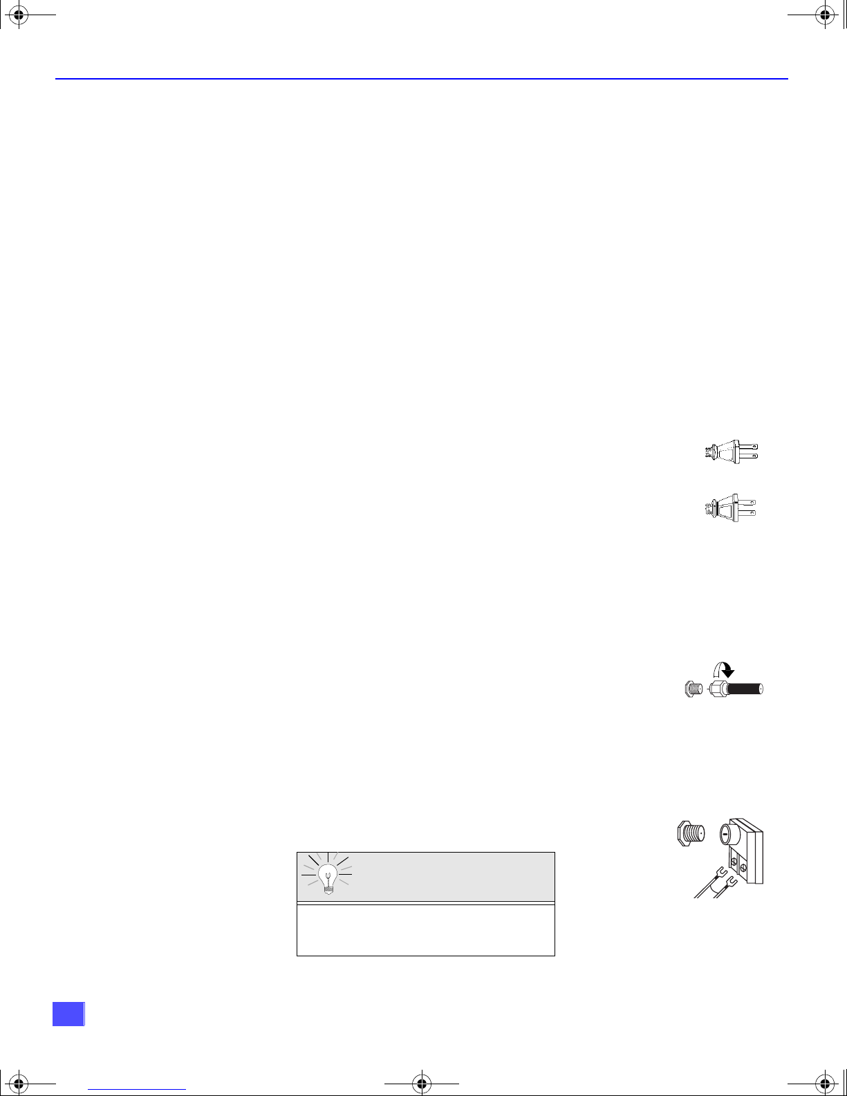
Cable / Antenna
CAUTION: TO PREVEN T ELECTRIC SHO CK, MATCH WIDE BLADE O F PLU G TO
WIDE SLOT OF AC OUTLET AND FULLY INSERT. DO NOT USE A PLUG WITH A
RECEPTACLE OR OTHER OUTLET UNLESS THE BLADE CAN BE FULLY
INSERTED TO PREVENT BLADE EXPOSURE. FOR SOME MODELS THAT ARE
NON-POLARIZED, THE USE OF AN AC ADAPTOR CONNECTOR MAY
BE NECESSARY.
For proper reception, either a cable or antenna connection is required.
Cable Connection
Incoming Cable from
Connect the cable supplied by your local cable company.
Note: A cable converter box may be required for proper reception.
Check with your local cable company for compatibility
requirements.
Antenna Connections
• For proper reception of VHF/UHF channels, an external antenna is required. For
best reception an outdoor antenna is recommended.
• Connect home antenna to ANT1 connection on back of
television. Select TV mode and ANT1 in the SET UP menu
under Prog Chan.
Incoming Cable from
Polarized plug
Non-Polarized plug
Cable Company
75 Ohm VHF/UHF
on back of PTV
Home Antenna
4
Cable Preset
Cable Mode is preset at the factory.
Antenna users must change to TV Mode and
ANT 1 in the Set Up menu.
B0342E Production.fm Page 5 Wednesday, February 7, 2001 11:10 AM
Optional Equipment Connections
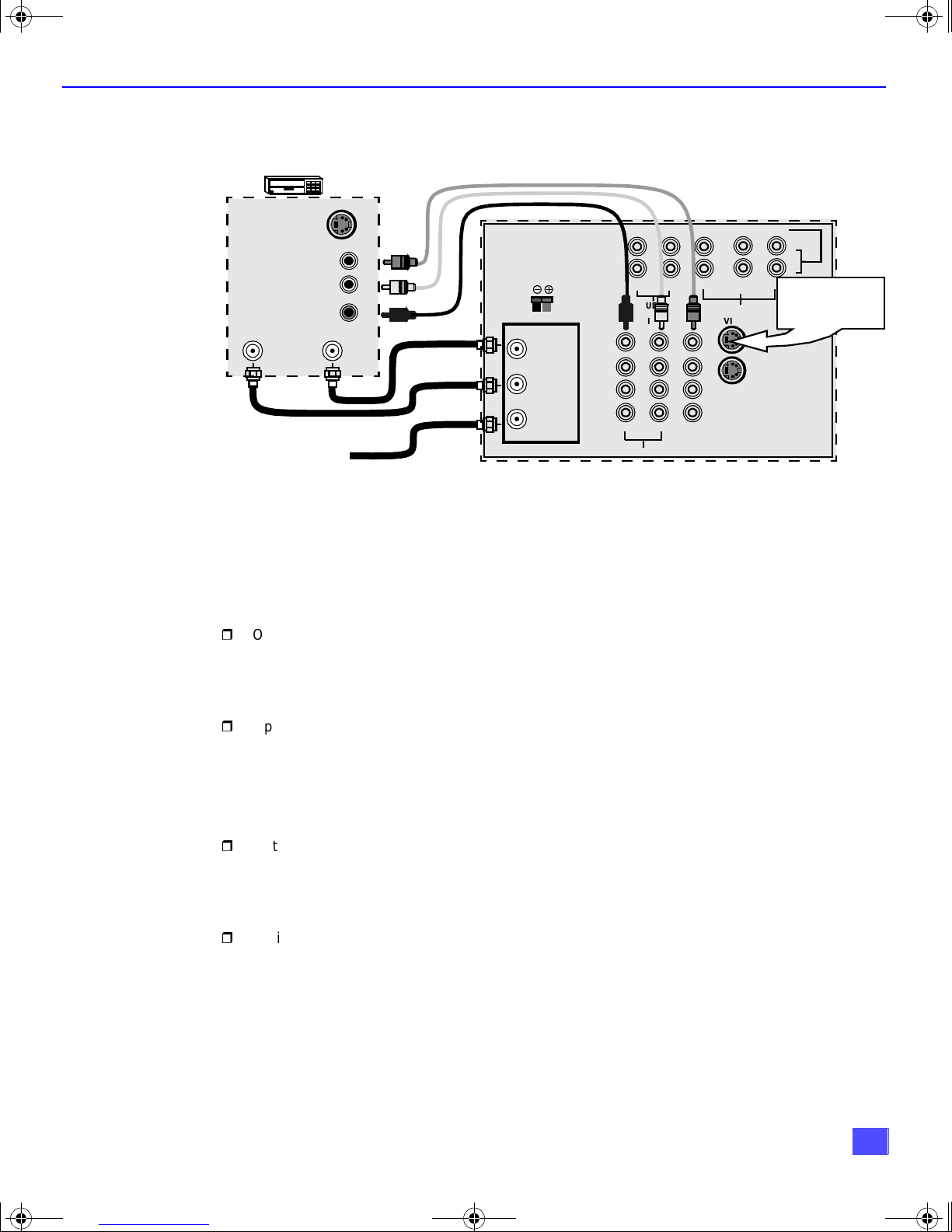
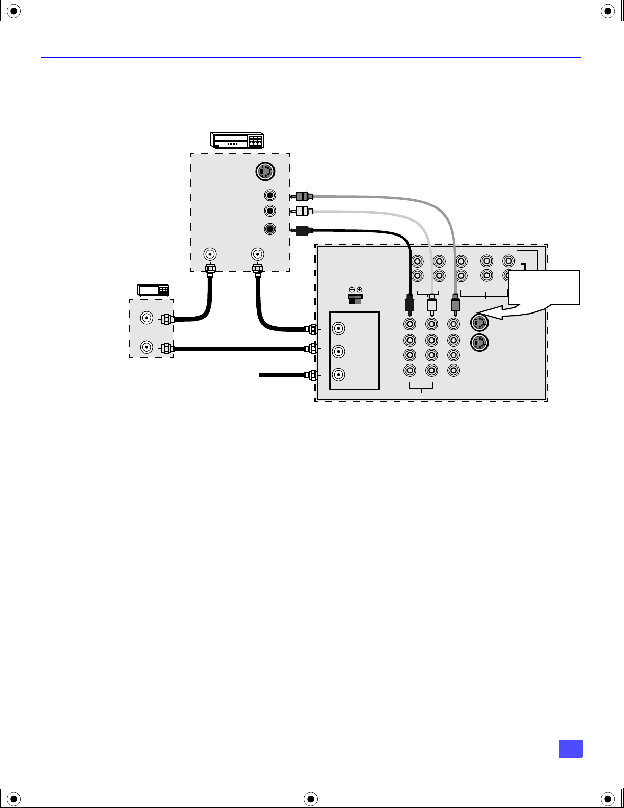
VCR Connection
Follow this diagram when connecting your tel ev is ion t o a VC R only.
I
NSTALLATION
VCR
S-VIDEO OUT
VIDEO OUT
AUDIO OUT
ANT INPUT
CABLES NOT SUPPLIED
Incoming Cable
ANT OUTPUT
CENTER CHANNEL INPUT
L
R
12Ω 50W (DIN) MAX
ANT 2
SPLIT
OUT
ANT 1
R
R-AUDIO-L
R
TO AUDIO AMP
TERMINALS ON BACK OF PTV
COMPONENT VIDEO INPUT
P
VIDEO
PROG .
OUT
PB Y
R
VIDEO
S-VIDEO
L
AUDIO
L
1
2
Use either the
S-Video or Video
connection.
INPUT 1
INPUT 2
INPUT 3
Note: The remote control must be programmed with supplied codes to operate the VCR. See
Programming the Remote Control in the Remote Control Quick Reference Guide.
Viewing a television program
Procedure
1. Select ANT1 in the SET UP menu under Prog Chan (Program Channels).
2. Tune the television to the television progra m you want to view.
Viewing a video
Procedure
r
Option A
1. Select ANT1 in the SET UP menu under Prog Chan (Program Channels).
2. Press the TV/VIDEO button on the remote control to select the video input (VIDEO 1,
VIDEO 2, etc.) connected to your VCR.
3. Begin the video.
r
Option B
1. Select ANT2 in the SET UP menu under Prog Chan (Program Channels).
2. Tune the television to Channel 3 or 4, depending on your VCR.
3. Begin the video.
Recording a television program
Procedure
r
Option A (Recording a nd vi ewing the same progra m)
1. Select ANT2 in the SET UP menu under Prog Chan (Program Channels).
2. Tune the television to Channel 3 or 4, depending on your VCR.
3. Using the VCR , tu ne to t he t el ev is io n pr og ram you want to record.
4. Begin recordi ng.
r
Option B (Recording o ne pr ogram while viewing anot her program)
1. Select ANT1 in the SET UP menu under Prog Chan (Program Channels).
2. Press the TV/VIDEO button on the remote control to select the video input (VIDEO 1,
VIDEO 2, etc.) connected to your VCR.
3. Using the VCR , tu ne to t he t el ev is io n pr og ram you want to record.
4. Begin recordi ng.
5. Press the TV/VIDEO bu tton on the remote control to swi tch back to TV mode.
6. Tune the television to the television progra m you want to view.
5
B0342E Production.fm Page 6 Wednesday, February 7, 2001 11:10 AM
I
NSTALLATION
Optional Equipment Connections (Cont.)
Open the door on the PTV front panel to use the connections for your optional
equipment (Pal mcorder, VCR, or oth er video components). S elect input 4 mo de by
pressing TV/VIDEO button.
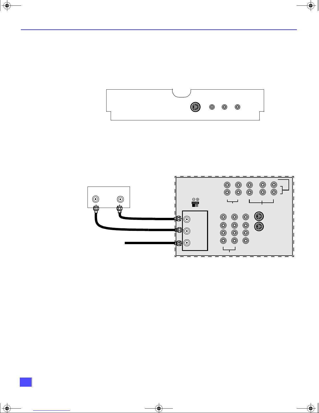
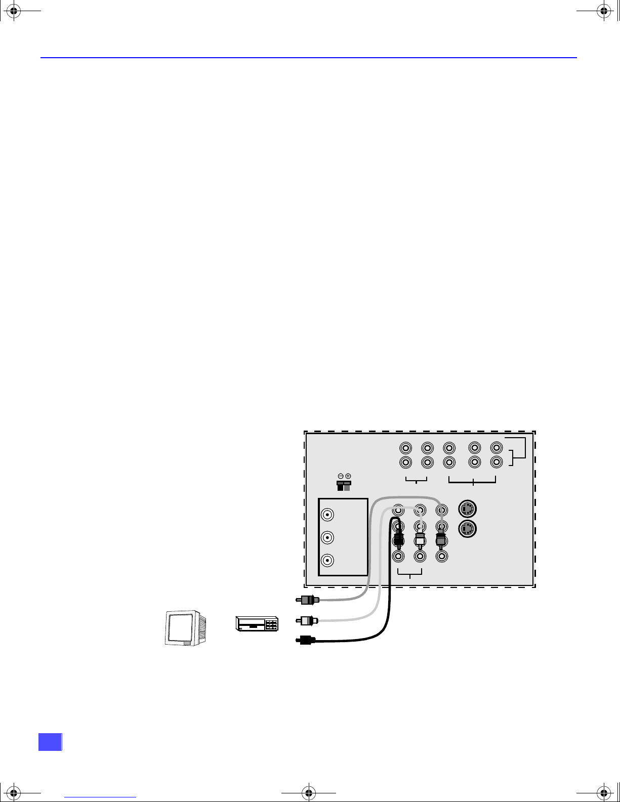
Cable Box Connection
Follow this diagram when connecting your television to a cable box only.
CONNECTIONS OF FRONT OF PTV
INPUT 4
S -VIDEO VIDEO L-AUDIO-R
TERMINALS ON BACK OF PTV
Cable Box
INPUT
Incoming Cable from
Cable Company
OUTPUT
CENTER CHANNEL INPUT
12Ω 50W (DIN) MAX
ANT 2
SPLIT
OUT
ANT 1
TO AUDIO AMP
COMPONENT VIDEO INPUT
L
R
AUDIO
R-AUDIO-L
R
VIDEO
L
PROG .
OUT
P
PB Y
R
VIDEO
S-VIDEO
1
2
INPUT 1
INPUT 2
INPUT 3
Note: The remote control must be programmed with supplied codes to operate the cable
box. See Programming the Remote Control in the Remote Control Quick Reference
Guide.
Viewing a premium (scrambled) cable channel
Procedure
1. Select ANT 2 in the SET UP menu under Prog Chan (Program Channels).
2. Tune the television to Channel 3.
3. Using the cable box, tune to the premium cable channel you want to view.
Note: To use special features such as Favori te Channe ls and Chann el Captio ns (se e Specia l
Features section for more information), ANT1 must be selected in the SET UP menu
under Prog Chan.
6
B0342E Production.fm Page 7 Wednesday, February 7, 2001 11:10 AM
Optional Equipment Connections (Cont.)
VCR and Cable Box Connection
Follow this diagram when connecting your television to both a VCR and a cable box.
VCR
S-VIDEO OUT
I
NSTALLATION
CABLES NOT SUPPLIED
CENTER CHANNEL INPUT
12Ω 50W (DIN) MAX
ANT 2
SPLIT
OUT
ANT 1
TO AUDIO AMP
COMPONENT VIDEO INPUT
L
R
AUDIO
R-AUDIO-L
R
VIDEO
L
PROG .
OUT
TERMINALS ON BACK OF PTV
1
2
P
PB Y
R
VIDEO
S-VIDEO
Use either the
S-Video or Video
connection.
INPUT 1
INPUT 2
INPUT 3
CABLE BOX
ANT OUTPUT
ANT INPUT
ANT INPUT
Incoming Cable
VIDEO OUT
L
AUDIO OUT
R
ANT OUTPUT
Note: The remote control must be programmed with supplied codes to operate the VCR and
cable box. See Programming the Remote Control in the Remote Control Quick
Reference Guide.
Viewing a premium (scrambled) cable channel
Procedure
1. Select ANT 2 in the SET UP menu under Prog Chan (Program Channels).
2. Tune the television to Channel 3.
3. Using the cable box, tune to the premium cable channel you want to view.
Note: To use special features such as Favori te Channe ls and Chann el Captio ns (se e Specia l
Features section for more information), ANT1 must be selected in the SET UP menu
under Prog Chan.
Recording a premium (scrambled) cable channel
Procedure
1. Select ANT2 in the SET UP menu under Prog Ch an.
2. Press the TV/VIDEO button on the remote control to select the video input ( VIDEO 1,
VIDEO 2, etc.) connected to your VCR.
3. Turn the VCR ON.
4. Tune the VCR to Channel 3 or 4, depending on your VCR.
5. Using your cable box, tune to the premium cable channel you want to record.
6. Begin recording.
Note: To view a different channel while recording:
• Select ANT1 in the SET UP menu under Prog Chan.
• Press the TV/VIDEO button on the remote control to select TV mode.
• Tune the television to a television program (except another premium cable channel).
7
B0342E Production.fm Page 8 Wednesday, February 7, 2001 11:10 AM
I
NSTALLATION
Optional Equipment Connections (Cont.)
Amplifier Connection (TO AUDIO AMP)
To listen through a separat e stere o system , con nect a n exter nal aud io ampli fier TO AUDIO AMP
inputs on back of television.
Note: TO AUDIO AMP terminals cannot be connected directly to external speakers.
Audio Adjustments
1. Select SPEAKERS ON located in the on screen AUDIO menu .
2. Set amplifier volume to minimum.
3. Adjust PTV volume to desired level.
4. Adjust amplifier volume to match the PTV.
5. Select SPEAKERS OFF & VARIABLE AUDIO OUT from AUDIO menu to control
speakers from the PTV or select FIXED AUDIO OUT to control speakers from the
external amplifier.
6. Volume, mute, bass, treble and balance are now controlled from the PTV, if you select
VARIABLE AUDIO OUT mode.
Program Out Connection (PROG. OUT)
To use the PTV audio and video with optional video equipment, use PROG. OUT and TO
AUDIO AMP terminals on the back of the PTV.
Procedure
1. Connect optional video equipment to PROG. OUT video and TO AUDIO AMP R/L
Audio terminals.
2. PROG OUT terminal display is the same as the on screen display.
3. See optional equipment manual for further instructions for recording or monitoring.
TERMINALS ON BACK OF PTV
COMPONENT VIDEO INPUT
1
2
INPUT 1
INPUT 2
INPUT 3
MONITOR
OR
VCR
CENTER CHANNEL INPUT
12Ω 50W (DIN) MAX
ANT 2
SPLIT
OUT
ANT 1
P
VIDEO
PROG .
OUT
PB Y
R
S-VIDEO
L
R
AUDIO
R-AUDIO-L
L
R
TO AUDIO AMP
CABLES NOT SUPPLIED
VIDEO
8
B0342E Production.fm Page 9 Wednesday, February 7, 2001 11:10 AM
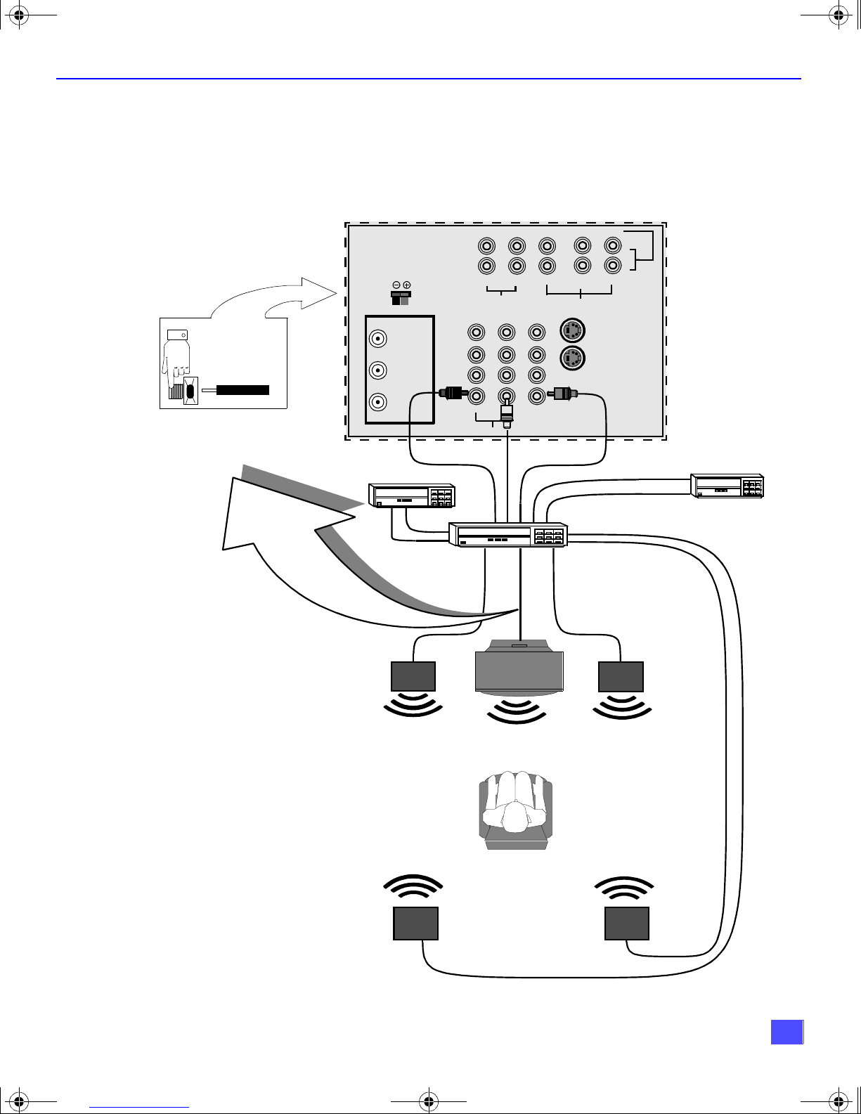
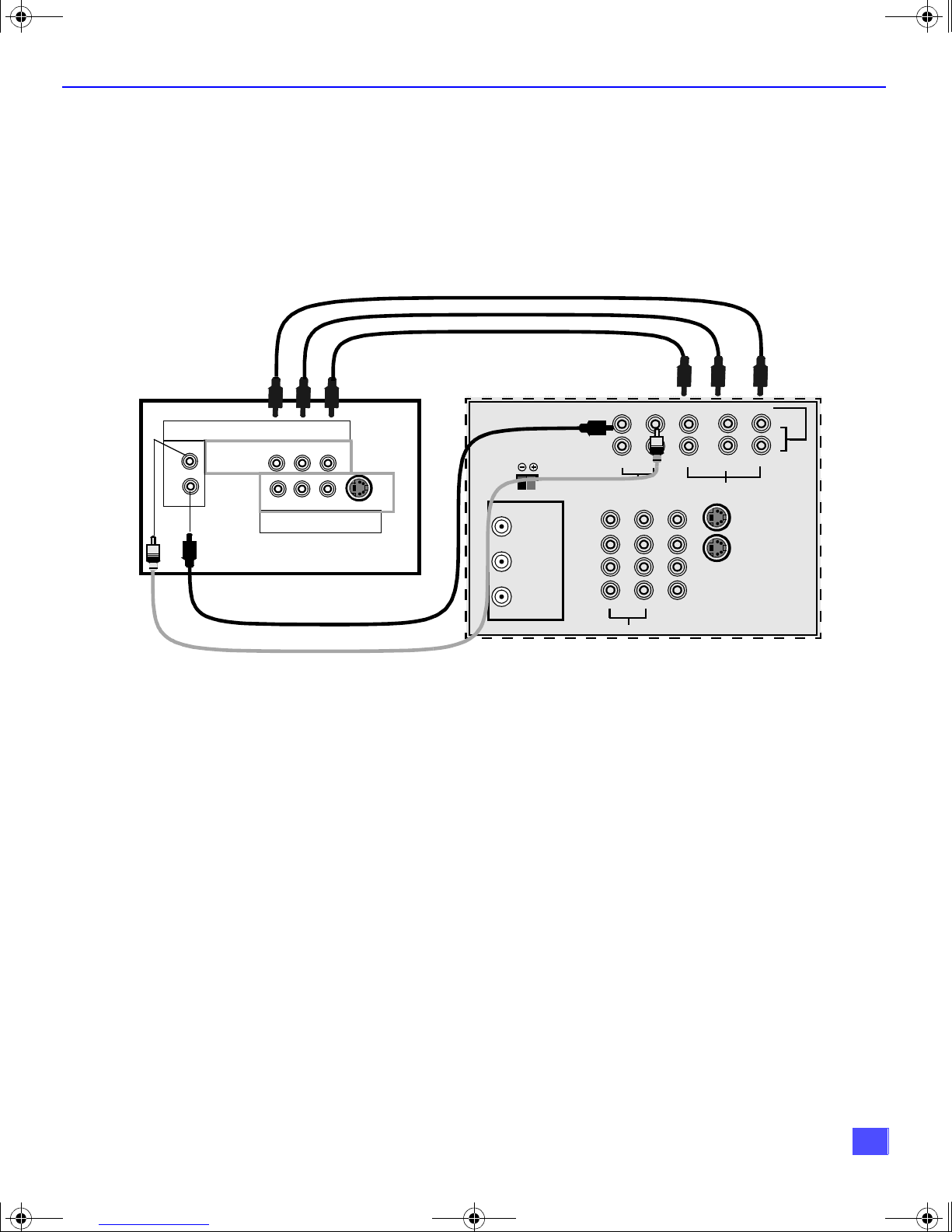
Dolby Center Channel Input Connection
Your PTV can be configured to use the PTV speakers as center channel speakers in
Dolby* surround sound tran smission. Connect a Dolby sur round amp lifier to CEN TER
CHANNEL INPUT on the back of the P TV as shown. DOLBY CE NTER MODE & FIXED
AUDIO OUT must be selected in the AUDIO Roller Guide
CENTER CHANNEL INPUT
12Ω 50W (DIN) MAX
TERMINALS ON BACK OF PTV
COMPONENT VIDEO INPUT
R
AUDIO
R-AUDIO-L
ANT 2
SPLIT
OUT
L
VIDEO
I
NSTALLATION
™** menu under SPEAKERS.
1
P
PB Y
R
VIDEO
S-VIDEO
2
INPUT 1
INPUT 2
INPUT 3
CENTER CHANNEL INPUT
(1) Push and hold down button.
(2) Insert bare wire into terminal
and release button.
ANT 1
Video Component
Left Front
Speaker
L
R
TO AUDIO AMP
PTV
PTV Speakers
Center Channel
PROG .
OUT
Dolby Surround
AMPLIFIER
From Center
Channel Output
Right Front
Speaker
VCR
*”Dolby” and “Pro-logic” are the trademarks of Dolby Laboratories Licensing Corporation.
**U.S. Patent Pending
Left Rear
Surround Speaker
Right Rear
Surround Speaker
9
B0342E Production.fm Page 10 Wednesday, February 7, 2001 11:10 AM
P
ICTURE IN PICTURE
(PIP) O
PERATION
Picture In Picture (PIP) Operation
This television includes a two tuner Picture In Picture (PIP) feature. This allows
watching two (2) li ve broadcasts at the same time without or with an exte rnal video
source (VCR).
Basic PIP Operation
Procedure
Press the PIP button on the remote control to display the
Note: The audio is for the Main Picture only.
1. Choose channels for the
down buttons.
2. Choose channels for the
buttons or by using the numeric keypad.
PIP
frame ons c reen.
PIP
frame by pressing the remote control PIP CHANNEL up/
Main Picture
by pressing the remote control CH up/down
SWAP Button
PIP Operation with a Cable Box
Procedure
r To view premium (scrambled) cable channels through your cable box in the
Note: Use this procedure if you want to watch premium cable channels in the Main Picture while
viewing a television program or video in the PIP frame.
1. Select ANT 2 in the SET UP menu under Prog Chan (Program Channels).
2. Tune television to Channel 3.
3. Press the PIP button on the remote control to display the
Note: The audio is for the Main Picture only.
4. Verify the cable box is ON.
5. Choose channels for the
6. Choose channels for the
and using the PIP CHANNEL up/down buttons.
Note: Swap is not available when using the cable box to tune channels. If your cable box has a video
output, it can be connected to the television to allow you to use all PIP functions. See the
equipment manual for more information. (Tune the PIP to the video input connected to the cable
box).
The SWAP button switches the PIP and Main
Picture source. Press the RECALL button for
onscreen PIP and Main Picture source status.
PIP
Main Picture
PIP frame
by tuning the cable box.
by pressing the TV button on the remote control
Main Pictur e
frame ons c reen.
:
10
B0342E Production.fm Page 11 Wednesday, February 7, 2001 11:10 AM
D
IGITAL
TV - SET-TOP BOX (DTV-STB) OR DVD C
Digital TV - Set-Top Box (DTV-STB) or DVD Connection
Use this diagram to connect the Panasonic DTV-STB (Digital TV-Set-Top Box) or DVD
to the back of your PTV.
DTV TERMINALS ON BACK OF DTV-STB OR DVD
COMPONENT VIDEO INPUT
DIGITAL TV OUTPUT
MAIN
VIDEO
R-AUDIO-L
Y
R-AUDIO-L
B
-VIDEO
R
P
P
NTSC OUTPUT
S-VIDEO
CENTER CHANNEL INPUT
12Ω 50W (DIN) MAX
ANT 2
SPLIT
OUT
R
AUDIO
R-AUDIO-L
L
VIDEO
P
PB Y
R
VIDEO
S-VIDEO
ONNECTION
1
2
INPUT 1
INPUT 2
INPUT 3
ANT 1
TO AUDIO AMP
L
R
PROG .
OUT
DTV TERMINALS ON BACK OF PTV
Note: There are three video inputs, Y, PB, and PR. Separate component color inputs provide
luminance and color separation. Use the L (left) and R (right) audio inputs.
11
B0342E Production.fm Page 12 Wednesday, February 7, 2001 11:10 AM
R
OLLER GUIDE MENU NAVIGATION
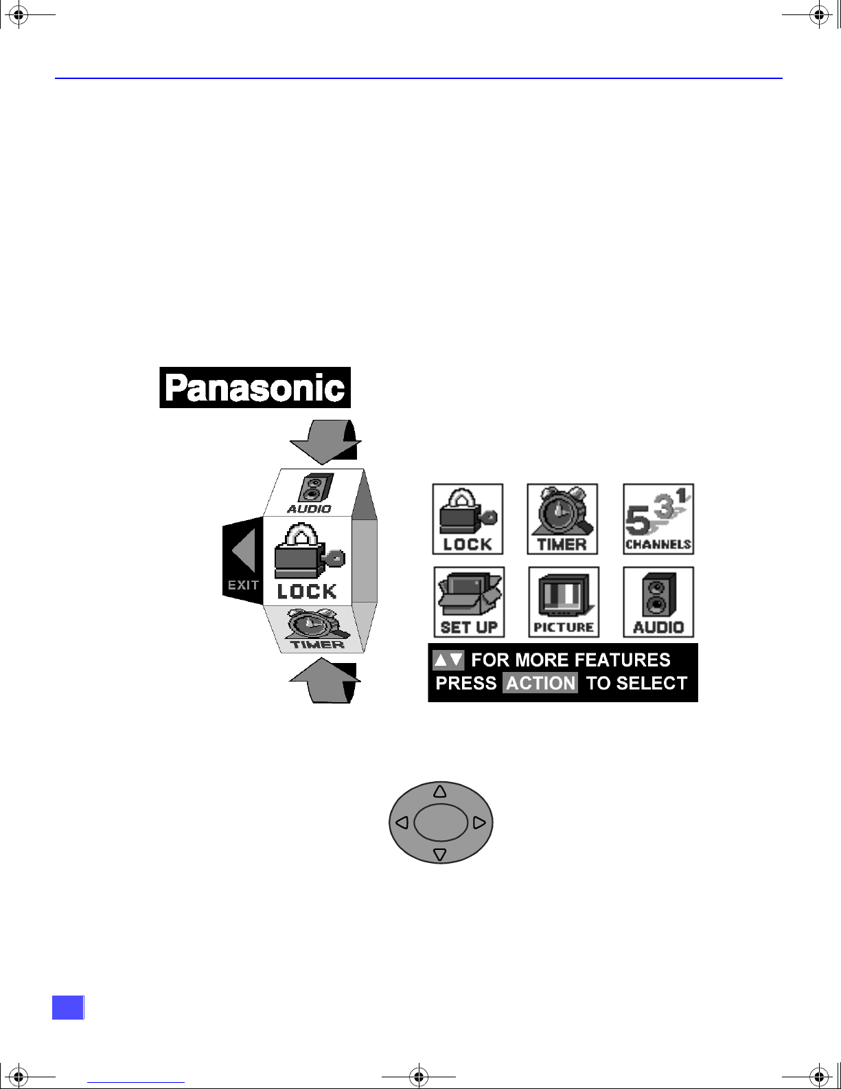
Roller Guide Menu Navigation
Procedure
1. Press the ACTION button in the middle of the large blue button on the Remote Control
to display the Roller Guide Menu.
2. Press the CH up/down to rotate the Roller Guide to the desired feature.
3. Press the ACTION button to display main menus and submenus.
4. Press the CH up/down buttons to highlight desired main menu feature.
5. Press the VOL right button to enter submenus.
6. Press the CH up/down buttons to highlight desired submenu feature.
7. Press the VOL right/left button to select or adjust feature.
8. Press the ACTION button twice to return to the Roller Guide Menu.
9. To exit the Roller Guide Menu, press the VOL left button.
Note: Be careful to press ACTION in the middle of the button. If you do not press in the
middle of the button, the (CH) channel or (VOL) volume keys may be activated.
ROLLER GUIDE MENU SELECTIONS
Remote ACTION / Navigation Button
CH
ACTION
VOL VOL
Remote Control Guide
The Remote Contr ol Quick Reference Guide is located within the package provided
with this P TV.
12
CH
B0342E Production.fm Page 13 Wednesday, February 7, 2001 11:10 AM
Roller Guide Feature Chart
M
ENU
PROG. CHAN
(Program Channels)
CC
(Closed Captioning)
R
OLLER GUIDE FEATURE CHART
D
ESCRIPTION
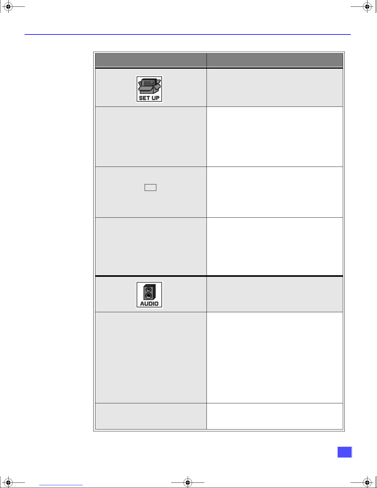
SET UP
r MODE - Select Cable or TV. See
Installation section in manual.
r ANTENNA - Select ANT 1 or ANT 2.
r AUTO PROGRAM - Automatically program
channels having a signal into memory.
r MANUAL PROGRAM - Manually add or
delete channels from memory.
r CC ON MUTE - Activate C1-C4 for Closed
Captioning display when the remote MUTE
button is pressed.
r CC MODE - Select T1-T4 or C1-C4 for
Closed Captioning, program guides and
other information.
OTHER ADJ.
AUDIO ADJ.
(Adjustments)
r AUTO POWER ON - Select SET to power
up the TV at th e same time as the Cable
Box or other components or select OFF.
r CONVERGENCE - Adjustment may be
required when the PTV is moved be cause
of the effects of the Earth’s magnetic field
on the projection tubes.
AUDIO
r MODE - Select STEREO, SAP (Second
Audio Program) or MONO. (Use MONO
when stereo signal is weak.)
r BASS - Increase or decrease the bass
response.
r TREBLE - Increase or decrease the treble
response.
r BALANCE - Emphasize the left/right
speaker volume.
r NORMAL - Reset BASS, TREBLE and
BALANCE to factory default.
OTHER ADJ.
(Adjustments)
r AI SOUND - Automatically adjust volume
to maintain a comfortable listening level.
(AI sound is not available in VIDEO mode).
13
B0342E Production.fm Page 14 Wednesday, February 7, 2001 11:10 AM
R
OLLER GUIDE FEATURE CHART
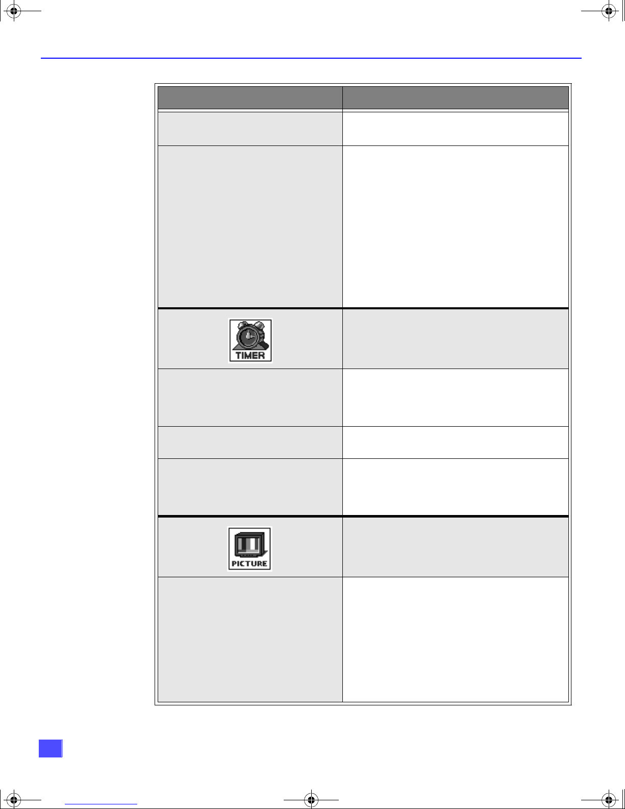
Roller Guide Feature Chart (Cont.)
M
ENU
D
ESCRIPTION
SURROUND
SPEAKERS
CLOCK SET
r SPATIALIZER® - Three dimensional
surround sound with two speakers.
r ON - PTV speakers operate normally.
r OFF & VAO (Variable Audio Output) -
PTV speakers off - audio adjustable by
PTV.
r OFF & FAO (Fixed Audio Output)-
PTV speakers off — audio adjustable only
by the external amplifier.
r DOLBY CENTER MODE & FIXED AUDIO
OUT - PTV speakers provide center
speakers for Dolby sound transmission
available on video or laser disc. (See
Installation section in manual.)
TIMER
r Set the time and the day of the week.
(Time will display onscreen after turning on
the television, pressing the RECALL button
or changing channels).
SLEEP
TIMER 1
TIMER 2
VIDEO ADJ.
(Adjustments)
r Set timer to turn off PTV in 30, 60 or
90 minutes. Select NO to turn timer off.
r Set one or both timers to automatically turn
television on and off at selected times, on
selected channels, and on selected days.
(Clock must be set to use Timer features).
PICTURE
r COLOR - Adjust desired color intensity.
r TINT - Adjust natural flesh tones.
r BRIGHTNESS - Adjust dark areas for crisp
detail.
r PICTURE - Adjust white areas of picture.
r SHARPNESS - Adjust clarity of outline
detail.
r NORMAL- Reset all picture adjustments to
factory default settings.
14
 Loading...