

Panasonic PT52LCX66 - MULTI MEDIA DISPLAY, PT-56LCX66, PT-61LCX66, PT-52LCX16, PT-56LCX16 Service Manual
ORDER NO. MKE0605850CE
Multi Media Display
PT-52LCX66
PT-56LCX66
PT-61LCX66
PT-52LCX16
PT-56LCX16
B2
© 2006 Panasonic Shikoku Electronics Co., Ltd. All
rights reserved. Unauthorized copying and
distribution is a violation of law.
PT-52LCX66 / PT-56LCX66 / PT-61LCX66 / PT-52LCX16 / PT-56LCX16
CONTENTS
Page Page
1 Safety Precautions 3
1.1. General Guidelines
1.2. Leakage Current Cold Check
1.3. Leakage Current Hot Check
1.4. UV-Precaution
2 Warning
2.1. Prevention of Electro Static Discharge (ESD) to
Electrostatically Sensitive (ES) Devices
3 Service Navigation
3.1. Introduction
3.2. About Lead Free Solder (PbF)
4 Specifications
5 Location of Controls and Components
5.1. Operation Instructions
5.2. Replacement of Lamp
6 Service Mode
7 Troubleshooting Guide
7.1. Troubleshooting Hints for Block Level Repair
8 Disassembly and Assembly Instructions
8.1. Cabinet Section
9 Measurements and Adjustments
9.1. Adjustment Procedures 1
10 Maintenance
10.1. Cleaning Methods
11 Block Diagrams
12 Schematic Diagrams
10
11
21
21
32
32
47
47
50
50
51
61
3
3
3
3
4
4
5
5
5
6
7
7
12.1. SCHEMATIC DIAGRAM AND CIRCUIT BOARD LAYOUT
NOTES
12.2. INTERCONNECTION SCHEMATIC DIAGRAM
12.3. FRONT JACK / OPERATION SCHEMATIC DIAGRAM
12.4. POWER SWITCH / THERMISTOR 2 / COVER SWITCH
SCHEMATIC DIAGRAMS
12.5. VOLTAGE CHART
13 Printed Circuit Board
13.1. FRONT JACK / OPERATION P.C.B. / POWER SWITCH
P.C.B. / THERMISTOR 2 P.C.B. / COVER SWITCH
P.C.B.
14 Ex ploded Views
14.1. MAIN PARTS SECTION
14.2. BASE BODY SECTION
14.3. DISPLAY SECTION
14.4. SCREEN SECTION
14.5. PROJECTION SECTION
14.6. TV UNIT SECTION
14.7. PACKING PARTS AND ACCESSORIES SECTION
15 Replacement Parts List
15.1. REPLACEMENT NOTES
15.2. MECHANICAL REPLACEMENT PARTS LIST
15.3. OPTIONAL ACCESSORY REPLACEMENT PARTS LIST
15.4. ELECTRICAL REPLACEMENT PARTS LIST
61
62
63
64
65
67
67
69
69
71
72
74
76
77
78
79
79
80
81
81
2
1 Safety Precautions
1.1. General Guidelines
1. For continued safety, no modification of any circuit should
be attempted.
2. Disconnect AC Plug before disassembling this unit.
3. It is advisable to use an isolation transformer in the AC
supply before servicing.
4. When servicing, observe the original lead dress. If a short
circuit is found, replace all parts which have been
overheated or damaged by the short circuit.
5. After servicing, see to it that all the protective devices such
as insulation barriers, insulation papers, shield, and
isolation R-C combinations etc. are properly installed.
6. After servicing, be sure to restore the wires, leads,
insulation barriers, shields, etc.
7. After servicing, make the leakage current checks to prevent
the customer from being exposed to shock hazards.
Caution:
Use a separate Isolation Transformer for this unit when
servicing.
PT-52LCX66 / PT-56LCX66 / PT-61LCX66 / PT-52LCX16 / PT-56LCX16
Figure 1
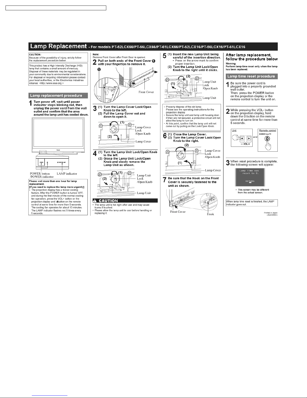
1.4. UV-Precaution
1. Be sure to disconnect the AC Plug when replacing the
lamp.
2. Since the lamp reaches a very high temperature during its
operation, wait until it has completely cooled off when
replacing the Lamp Unit.
3. The lamp emits small amounts of UV-Radiation.
Avoid direct-eye contact by covering the Lamp and wearing
the UV protective glasses.
4. The high pressure lamp involves a risk of explosion.
1.2. Leakage Current Cold Check
1. Unplug the AC cord and connect a jumper between the two
prongs on the plug.
2. For physically operated power switches, turn power on.
Otherwise skip step 2.
3. Measure the resistance value, with an ohmmeter, between
the jumpered AC plug and each exposed metallic cabinet
part on the receiver, such as screwheads, connectors, etc.
When the exposed metallic part has a return path to the
chassis, the reading should be between 1 MΩ and 12 MΩ.
When the exposed metal does not have a return path to the
chassis, the reading must be infinity.
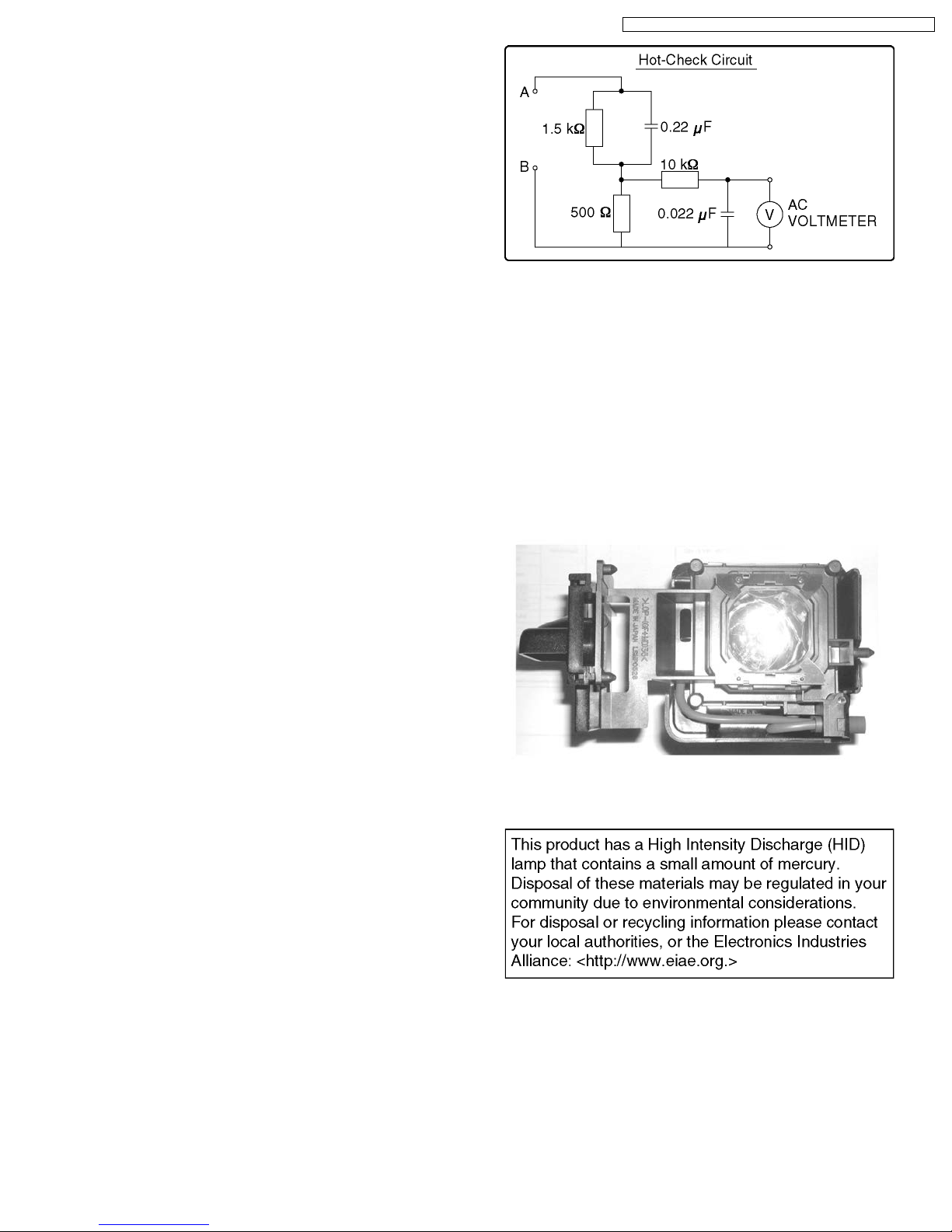
1.3. Leakage Current Hot Check
1. Plug the AC cord directly into the AC outlet.
Do not use an isolation transformer for this check.
2. Connect "A" to exposed metallic part on the set. And
connect "B" to a good earth ground, as shown in Figure 1.
3. Use an AC voltmeter, with 1 kΩ/V or more sensitivity, to
measure the potential across the resistor.
4. Check each exposed metallic part, and measure the
voltage at each point.
5. Reverse the AC plug in theAC outlet and repeat each of the
above measurements.
6. The potential at any point should not exceed 0.25 V RMS.
A leakage current tester (Simpson Model 228 equivalent)
may be used to make the hot checks. Leakage current must
not exceed 1/2 mA. In case a measurement is outside of
the limits specified, there is a possibility of shock hazard,
and the receiver should be repaired and rechecked before
it is returned to the customer.
Figure 2
3

PT-52LCX66 / PT-56LCX66 / PT-61LCX66 / PT-52LCX16 / PT-56LCX16
2 Warning
2.1. Prevention of Electro Static Discharge (ESD) to Electrostatically
Sensitive (ES) Devices
Some semiconductor (solid state) devices can be damaged easily by static electricity. Such components commonly are called
Electrostatically Sensitive (ES) Devices. Examples of typical ES devices are integrated circuits and some field-effect transistors and
semiconductor "chip" components. The following techniques should be used to help reduce the incidence of component damage
caused by electro static discharge (ESD).
1. Immediately before handling any semiconductor component or semiconductor-equipped assembly, drain off any ESD on your
body by touching a known earth ground. Alternatively, obtain and wear a commercially available discharging ESD wrist strap,
which should be removed for potential shock reasons prior to applying power to the unit under test.
2. After removing an electrical assembly equipped with ES devices, place the assembly on a conductive surface such as
aluminum foil, to prevent electrostatic charge buildup or exposure of the assembly.
3. Use only a grounded-tip soldering iron to solder or unsolder ES devices.
4. Use only an antistatic solder removal device. Some solder removal devices not classified as "antistatic (ESD protected)" can
generate electrical charge sufficient to damage ES devices.
5. Do not use freon-propelled chemicals. These can generate electrical charges sufficient to damage ES devices.
6. Do not remove a replacement ES device from its protective package until immediately before you are ready to install it. (Most
replacement ES devices are packaged with leads electrically shorted together by conductive foam, aluminum foil or comparable
conductive material).
7. Immediately before removing the protective material from the leads of a replacement ES device, touch the protective material
to the chassis or circuit assembly into which the device will be installed.
CAUTION :
Be sure no power is applied to the chassis or circuit, and observe all other safety precautions.
8. Minimize bodily motions when handling unpackaged replacement ES devices. (Otherwise harmless motion such as the
brushing together of your clothes fabric or the lifting of your foot from a carpeted floor can generate static electricity (ESD)
sufficient to damage an ES device).
4
PT-52LCX66 / PT-56LCX66 / PT-61LCX66 / PT-52LCX16 / PT-56LCX16
3 Service Navigation
3.1. Introduction
This service manual contains technical information which will allow service personnel´s to understand and service this model.
Please place orders using the parts list and not the drawing reference numbers.
If the circuit is changed or modified, this information will be followed by supplement service manual to be filed with original service
manual.
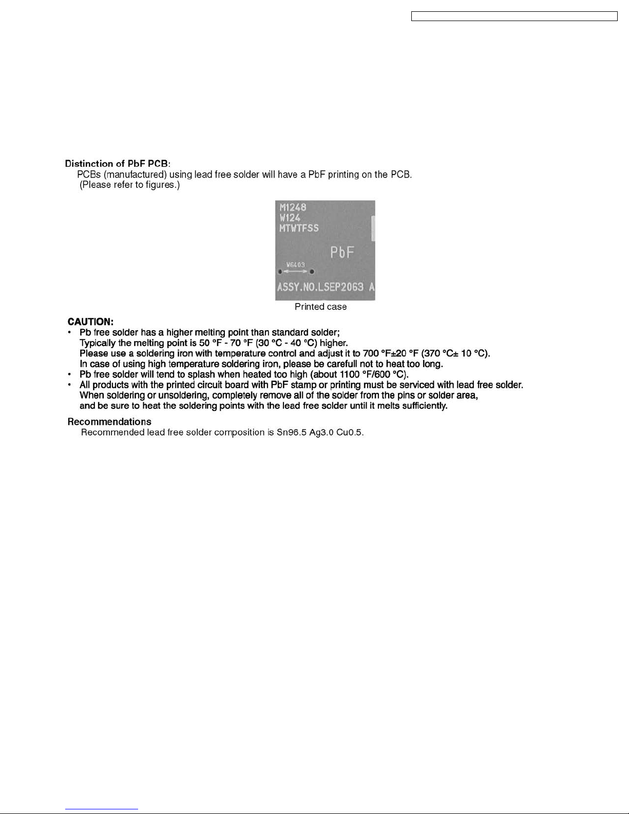
3.2. About Lead Free Solder (PbF)
5
PT-52LCX66 / PT-56LCX66 / PT-61LCX66 / PT-52LCX16 / PT-56LCX16
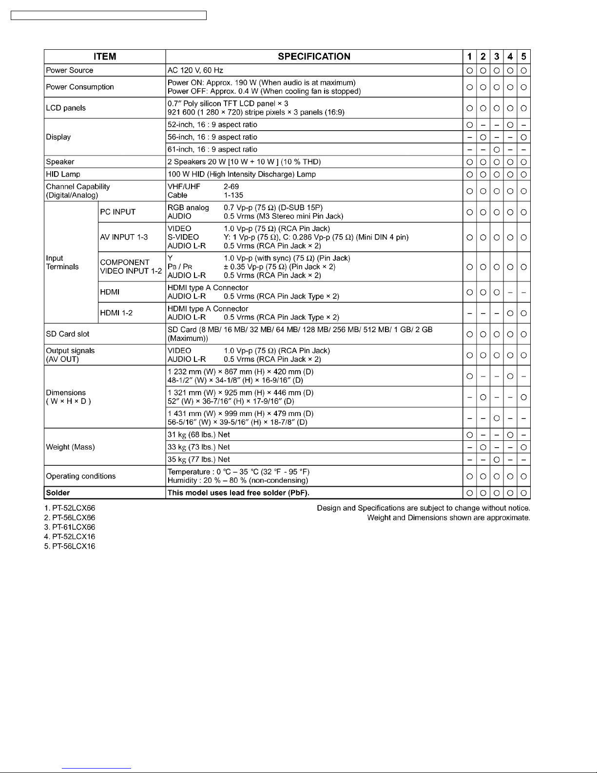
4 Specifications
6
PT-52LCX66 / PT-56LCX66 / PT-61LCX66 / PT-52LCX16 / PT-56LCX16
5 Location of Controls and Components
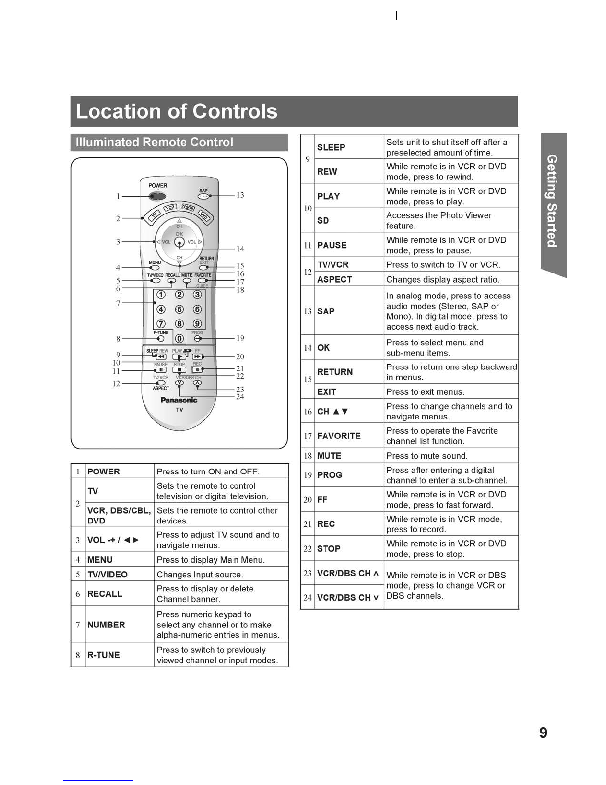
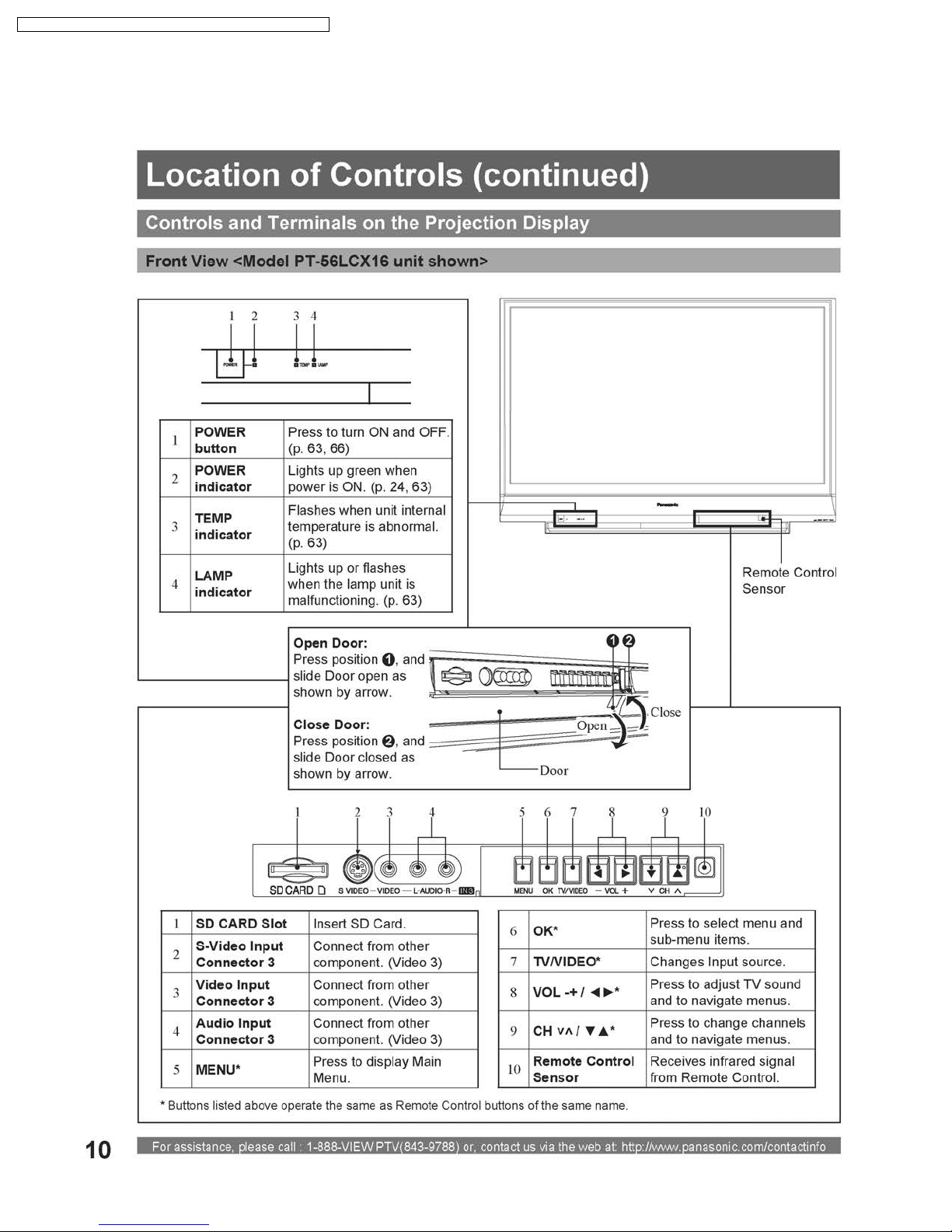
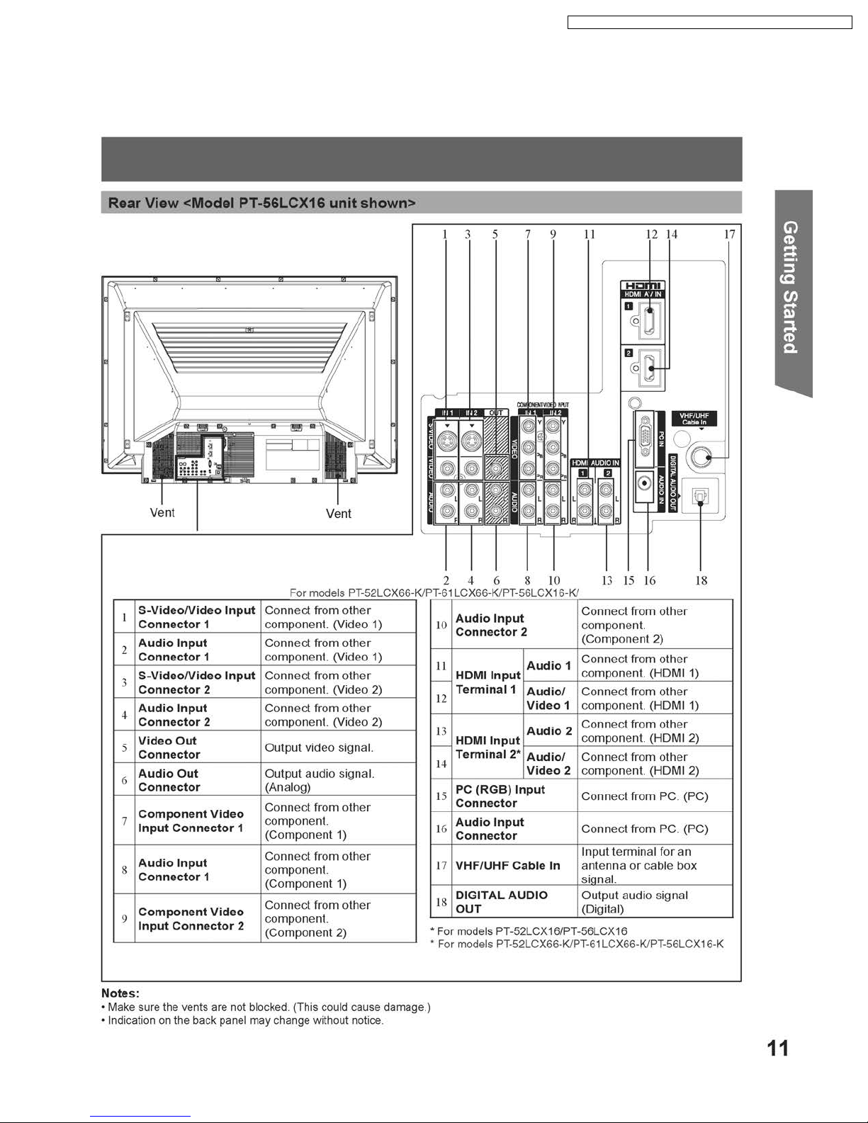
5.1. Operation Instructions
7
PT-52LCX66 / PT-56LCX66 / PT-61LCX66 / PT-52LCX16 / PT-56LCX16
8
PT-52LCX66 / PT-56LCX66 / PT-61LCX66 / PT-52LCX16 / PT-56LCX16
9
PT-52LCX66 / PT-56LCX66 / PT-61LCX66 / PT-52LCX16 / PT-56LCX16
5.2. Replacement of Lamp
10
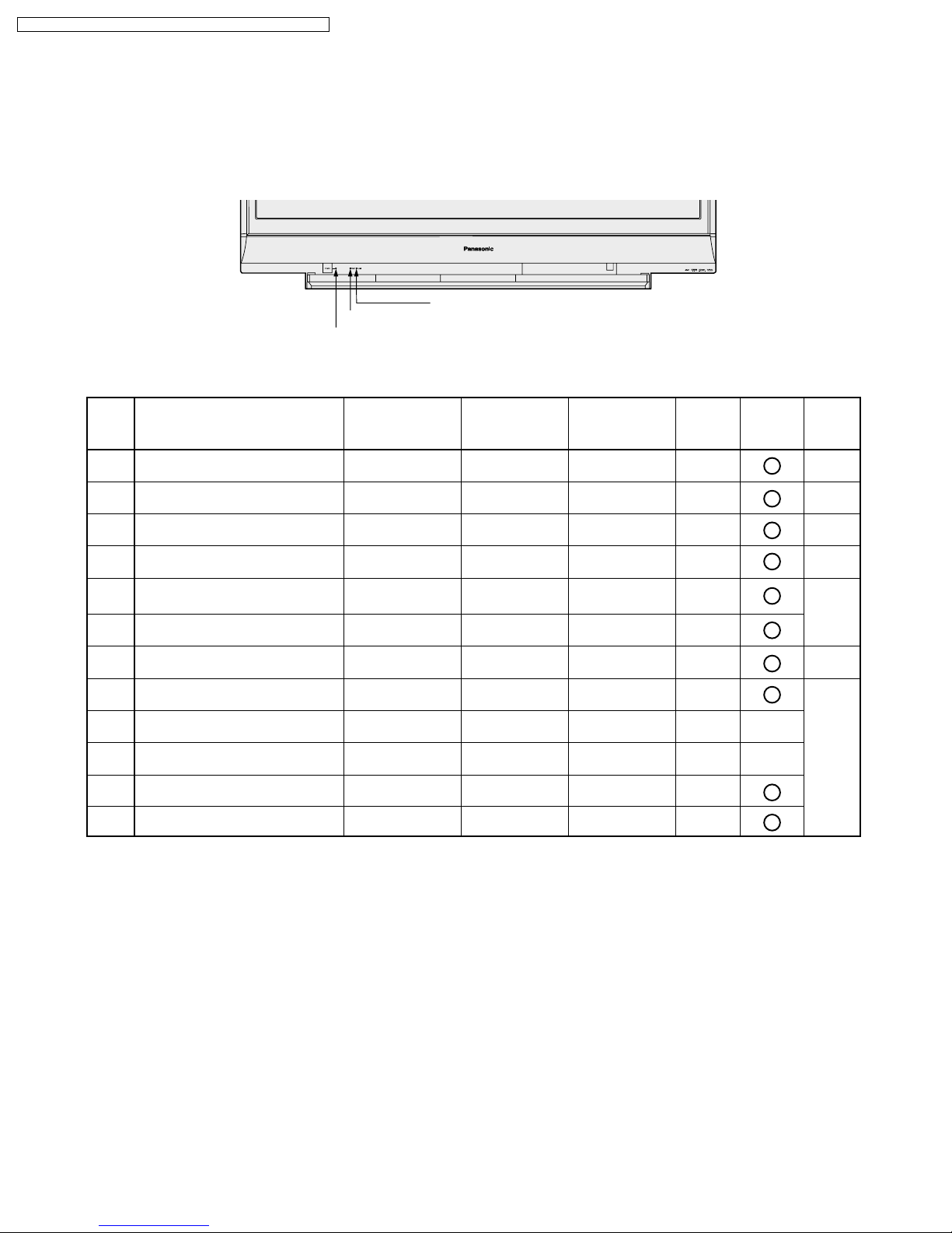
6 Service Mode
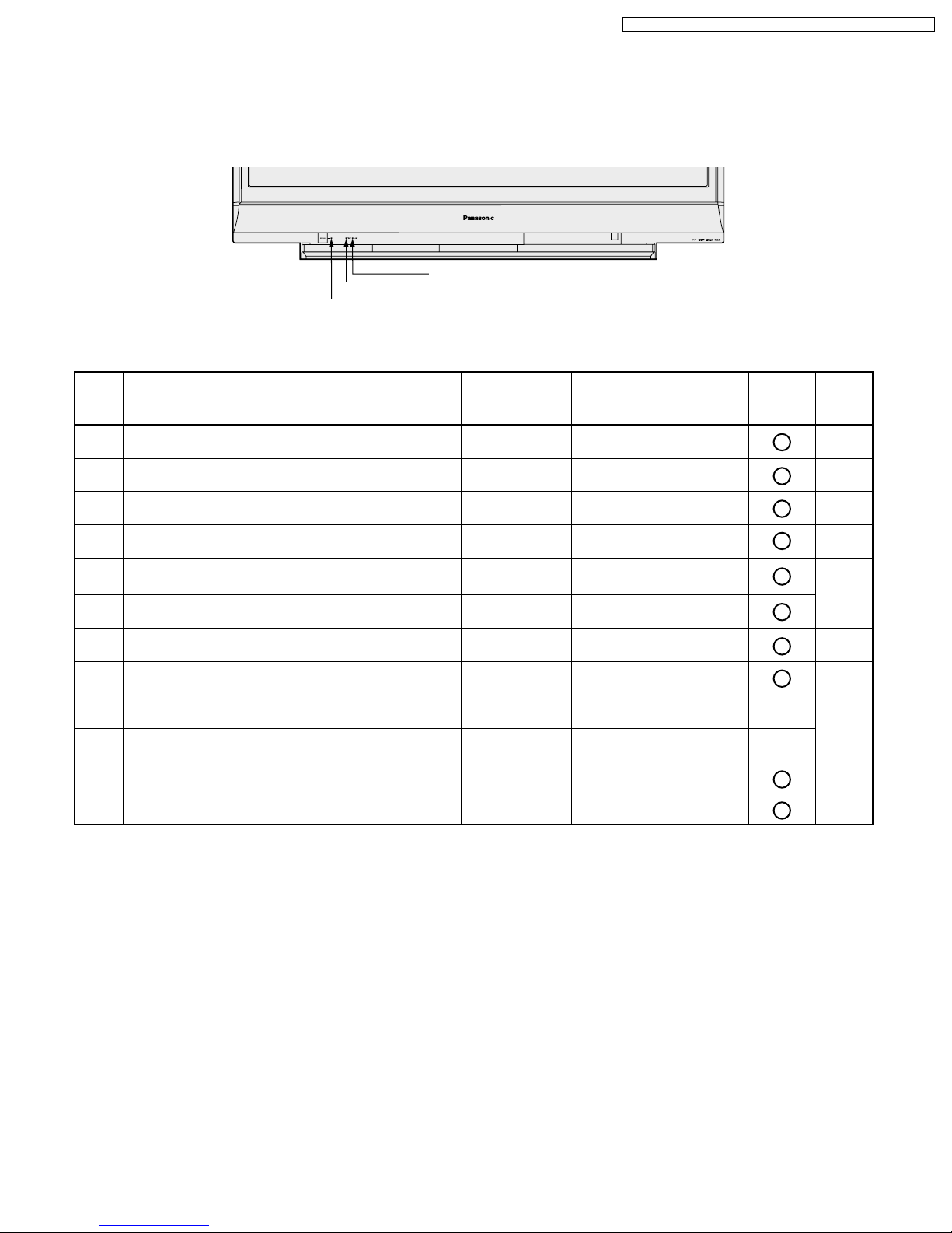
LED INDICATIONS FOR ERROR CONDITIONS
Each LED indication facilitates finding the cause of an error.
When an error is detected, the Lamp goes off and the LEDs on the front flash.
LAMP LED
TEMP LED
POWER LED
PT-52LCX66 / PT-56LCX66 / PT-61LCX66 / PT-52LCX16 / PT-56LCX16
(Note 1, 2) (Note 3)(Note 4)
Error No.
1)
2)
3)
4)
5)
6)
7)
8)
9)
10)
11)
12)
Note:
1. The detected SOS Error 1) 2) 3) 4) 11) 12) data will be stored in the EEPROM.
2.SOS (Error) information is displayed in Service Mode (4/4).
3.LAMP OFF: The LED will flash immediately after the Lamp goes off.
4.In case of Error 9) or 10), the unit will not shut off and Dynamic Iris setting in Adv. adjust of Picture Menu will be
changed to "OFF" automatically. When the unit is turned off and turned back on, Dynamic Iris "OFF" setting remains.
Lamp LED will not flash as long as Dynamic Iris setting in Adv. adjust of Picture Menu is set to "ON" manually.
Error Information
SOS2 (Over voltage/current)
Fan 1, Fan 2 or Fan 3 stops
Abnormal voltage (DT+5V line)
IC5001 (GC4Pro) communication
error
Temperature Sensor shorted or open
(Thermistor 2 P.C.B.)
Abnormal temperature
(Thermistor 2 P.C.B.)
Clogged Air Filter
Abnormal Lamp
Iris Mechanism hardware error
Iris calibration error
Lamp Cover open
Abnormal voltage (+17V, +9V, +5V line)
for LCD Drive P.C.B.
POWER LED
flashes orange
1
2
3
5
-
-
-
-
-
-
7
8
TEMP LED
flashes red
- -
-
-
-
2
3
6
-
-
-
-
-
LAMP LED
flashes red
-
-
-
-
--
-
SOS
H10SOS2
H20FANST
H30DT9V
H50GC4PR
1
2
3
-
-
(H70LAMCV)
(H80LCDDV)
-
-
-
-
-
LAMP OFF
RESET
Power
ON/OFF
AC
ON/OFF
Power
ON/OFF
AC
ON/OFF
Power
ON/OFF
Clean
Air Filter
-
Power
-
ON/OFF
11

PT-52LCX66 / PT-56LCX66 / PT-61LCX66 / PT-52LCX16 / PT-56LCX16
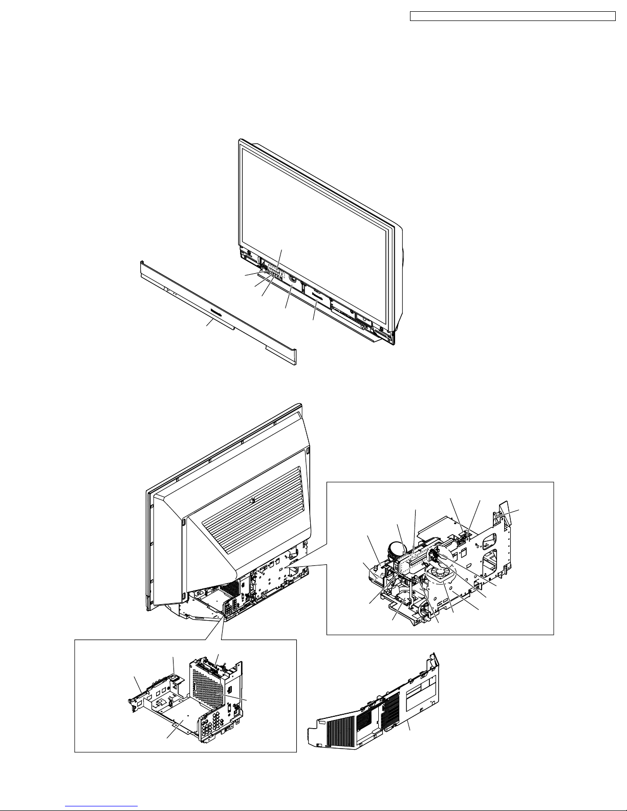
MAIN PARTS LOCATION
<Front View>
TEMP LED
POWER LED
Front Cover Unit
TEMP LED
LAMP LED
Power Switch P.C.B.
Lamp Cover
Optical Cover
<Rear View>
LAMP LED
Cover Switch P.C.B.
Fan Case Unit
(Fan 1)
Projection Unit & Top Duct 3
Thermistor 2 P.C.B.
Air Filter
Thermal Fuse
Fan 3
SD Card P.C.B.
Front Jack
/Operation P.C.B.
Base P.C.B.
TV Unit & Digital Tuner P.C.B.
Digital T uner P.C.B.
Main P.C.B.
Air Filter
Air Filter
Iris P.C.B.
Note: There is not the Thermistor 1 P.C.B. in this unit.
Rear Cover
12
Fan 2
LCD Drive P.C.B.
Iris Unit
Power P.C.B.
Hall-S P.C.B.
PT-52LCX66 / PT-56LCX66 / PT-61LCX66 / PT-52LCX16 / PT-56LCX16
TO DISTINGUISH THE PROJECTION UNIT
The only difference between the 52/56 inch model and 61 inch
model of the Projection Unit is the LCD Drive P.C.B.
Therefore, see the stamp on the Lamp Wall to differentiate.
Also, the Focus Adjustment should be performed to match
each size of model after replacing the new Projection Unit or
the new Base Body Unit.
Note:
The Base Body Unit includes the Projection Unit.
Stamp
LSXA0771
LSXA0827
: for 52/56 inch models
: for 61 inch model
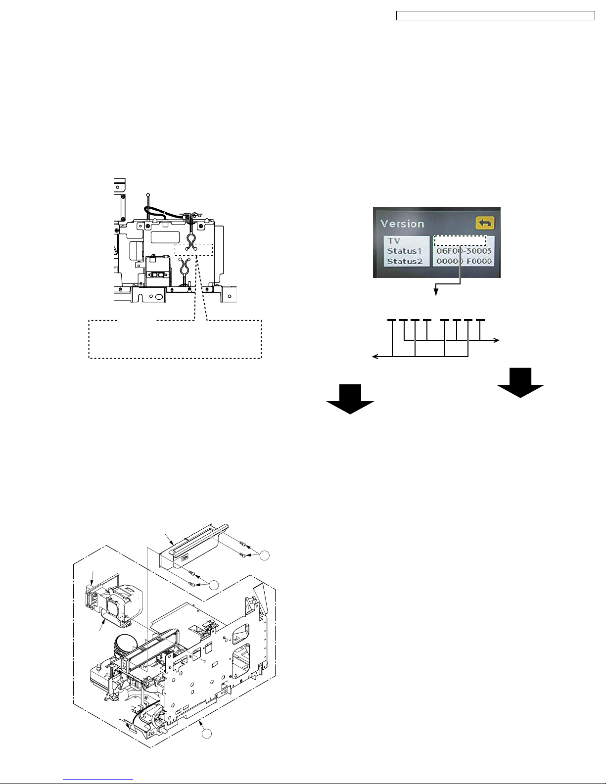
TO READ THE DIGITAL TUNER (PEAKS)
SOFTWARE VERSION AND TV
MICROCONTROLLER SOFTWARE
VERSION
1. Press MENU key with the power on.
2. Press CH UP/DOWN key and select "Setup."
Then press OK key.
3. Press CH UP/DOWN key and select "About."
Then press OK key.
4. Select "Version" and press OK key.
Version menu will appear as shown below.
Starting with the second digit from the right or from the left.
0120-4310
0120-4310
Read every
Read every
other number
from the right:
other number
from the left:
BEFORE REMOVING THE PROJECTION
UNIT FROM THE UNIT AT THE USER’S
LOCATION
When removing the Projection Unit, remove the Lamp Unit and
the Top Duct 3 Unit from the Projection Unit and keep them.
Then, reinstall this Lamp Unit and the Top Duct 3 Unit into the
new Projection Unit.
Top Duct 3 Unit
421
Knob
421
Lamp
Unit
TV Microcontroller software Ver. : 1.030
Digital Tuner (Peaks) software Ver. : 1.420
LVDS
Cable
21
Projection Unit
13

MODEL
PT-52LCX66
PT-56LCX66
PT-61LCX66
PT-52LCX16
PT-56LCX16
NOT USED
MARK
A
B
C
D
E
PT
Note:
Refer to Item 3 of Schematic Diagram Notes of
Schematic Diagram and Circuit Board Layout Notes,
for mark "PT."
PT-52LCX66 / PT-56LCX66 / PT-61LCX66 / PT-52LCX16 / PT-56LCX16
RESET USER’S MEMORY FUNCTIONS
Be sure to reset the user’s memory:
- After replacing the Digital Tuner P.C.B.
- If the secret code for V-chip has been forgotten.
- When moving the unit to a new location.
- When resetting SOS (Error) number records.
1. Turn on the power.
2. Press and hold the VOLUME DOWN button on the unit and
the OK key on the remote for more than 3 seconds. When
reset is finished, power shuts off automatically (the user’s
memory is reset).
CLOGGED AIR FILTER DETECTION
When a dirty or clogged air filter is detected, the OSD display
appears for 1 minute. And then the Lamp is turned OFF.
When this OSD display appears, remove the Projection Unit
from rear, and clean the air filters gently on the Projection Unit.
AIR FILTER CLEANING
IS RECOMMANDED AT THIS
TIME. FIRST TURN THE
UNIT OFF.
PLEASE CALL FOR
SERVICE.
UNIT WILL BE TURNED
OFF AFTER 1 MINUTE.
DO NOT UNPLUG AC CORD DURING
COOLING OPERATION
The lamp cooling fan will continue to operate for approximately
1 minute after the power is turned off.
At the same time, the POWER LED will flash red.
Do not disconnect the AC Cord from the power outlet and do
not open any circuit breakers while the cooling fan is still
operating.
HOT CIRCUIT
Primary circuit exists on the Power P.C.B.
This circuit is identified as "HOT" on the P.C.B. and in the
Service Manual. Use extreme care to prevent accidental shock
when servicing.
MODEL NO. IDENTIFICATION MARK
Use Marks shown in the chart below to distinguish the different
models included in this Service Manual.
14

PT-52LCX66 / PT-56LCX66 / PT-61LCX66 / PT-52LCX16 / PT-56LCX16
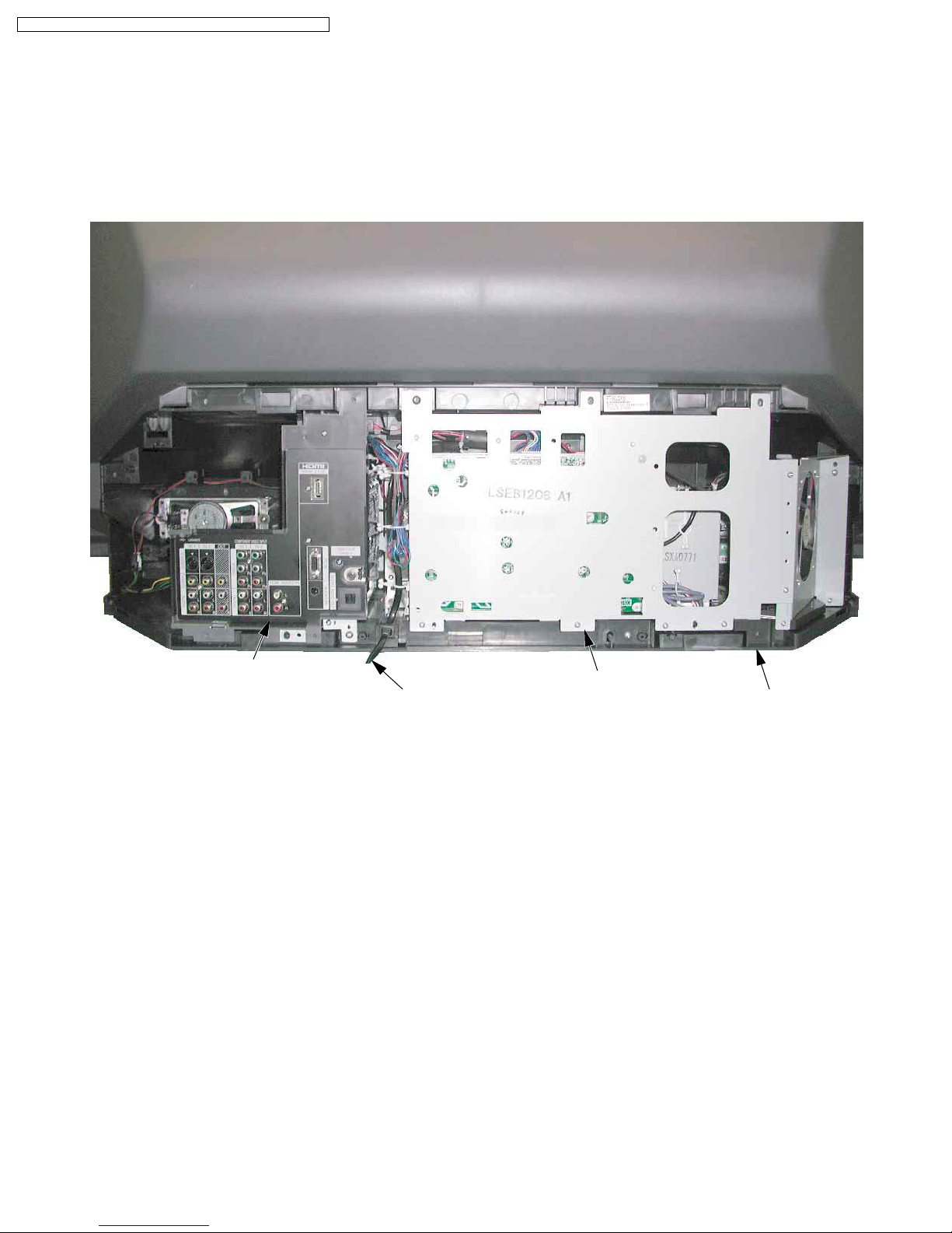
BEFORE REMOVING THE MAIN P.C.B. OR
THE TV UNIT FROM THE UNIT AT THE
USE’S LOCATION
Note:
The TV Unit includes the Main P.C.B.
CAUTION:
Be sure to make a note of the CURRENT LAMP value
1.
(value A) in Service Mode (1/4):
SERVICE Mode 1/4
LAMP OPERATION TIME
CURRENT LAMP: 2000h
OSD DISP : ON
LON COUNT : 153
BKSV: 4B 7E 3D CA FB
<Service Mode (1/4)>
Fig. 2
LAMP OPERATION TIME is stored in EEPROM on the
Main P.C.B. Therefore, before removing the Main P.C.B. or
the TV Unit at the user’s location, make a note of the
CURRENT LAMP value (value A) in Service Mode (1/4).
Then, after installing the new Main P.C.B. or the TV Unit at
the user’s location, set the CURRENT LAMP value to the
original value (value A) in Service Mode.
Otherwise, OSD and LED Lamp replacement indications
will be displayed at the wrong time.
Note:
In case it is impossible to make a note of the CURRENT
LAMP value because of a defective Main P.C.B., ask the
customer their daily average use and the approximate age
of the current Lamp. Then, calculate the CURRENT LAMP
value as follows and make a note.
Value A
(Changeable)
WHEN REINSTALLING THE MAIN P.C.B.
OR THE TV UNIT FROM THE UNIT AT THE
USE’S LOCATION
CAUTION:
1. Set CURRENT LAMP value to original value as follows.
1) Select CURRENT LAMP in Service Mode (1/4).
2) Press the VOLUME UP/DOWN key on the remote to
change to the original value (value A) that was noted
before removing the Main P.C.B. or the TV Unit at the
user’s location.
SERVICE Mode 1/4
LAMP OPERATION TIME
CURRENT LAMP: 2000h
OSD DISP : ON
LON COUNT : 153
BKSV: 48 BF 9D 72 B5
<Service Mode (1/4)>
Fig. 3
Service Mode Map
Enter:
VOLUME DOWN button + TV/VIDEO key
(on the front) (on the remote)
(for more than 5 seconds in power off condition)
Power ON
SERVICE Mode 1/4
LAMP OPERATION TIME
CURRENT LAMP: 2000h
OSD DISP : ON
LON COUNT : 153
BKSV: B0 3A 59 CD 66
CH DOWN key CH UP key
< Service Mode (1/4) >
Value A
(Changeable)
BKSV number
Daily average use
(hours) (days) (hours)
Approx. age CURRENT LAMP
X=
Note:
The TOTAL value can be set to the original value in Service
Mode (2/4) by similar method:
Before removing the Main P.C.B. at the user’s location,
make a note of the TOTAL value in Service Mode (2/4).
Then, after installing the new Main P.C.B. at the user’s
location, set the TOTAL value to the original value in
Service Mode.
15
SERVICE Mode 2/4
IR:1 UNIT:1
IC2301:1 3101:1 4002:1
4504:1 5000:1 5001:1
5801:1 6000:1 9502:1
TOTAL : 12345h
TU8200:1
E:06030301
IC6001 V:0005024
CH DOWN key
< Service Mode (2/4) >
CH UP key
SERVICE Mode 3/4
IC6001 PORT
P0:10101010 P8:---10110
P1:-1111100 P9:--111111
P2:00000000 PA:00000000
P3:00000000 PB:11111110
P4:--111110 PC:11111100
P5:10110101 PD:-----111
P6:01011001 PE:11000000
P7:10101001 PF:----0011
< Service Mode (3/4) >
CH DOWN key CH UP key
SERVICE Mode 4/4
-SOS-
LAST SOS H10SAFE 01
SAFE 10.40.50.50.40
H10SOS2 :01 H20FANST:00
H30DT5V
H50GC4PR:01
:00 H40ACLST:00
< Service Mode (4/4) >
CH DOWN key
Exit:
Power OFF.
PT-52LCX66 / PT-56LCX66 / PT-61LCX66 / PT-52LCX16 / PT-56LCX16
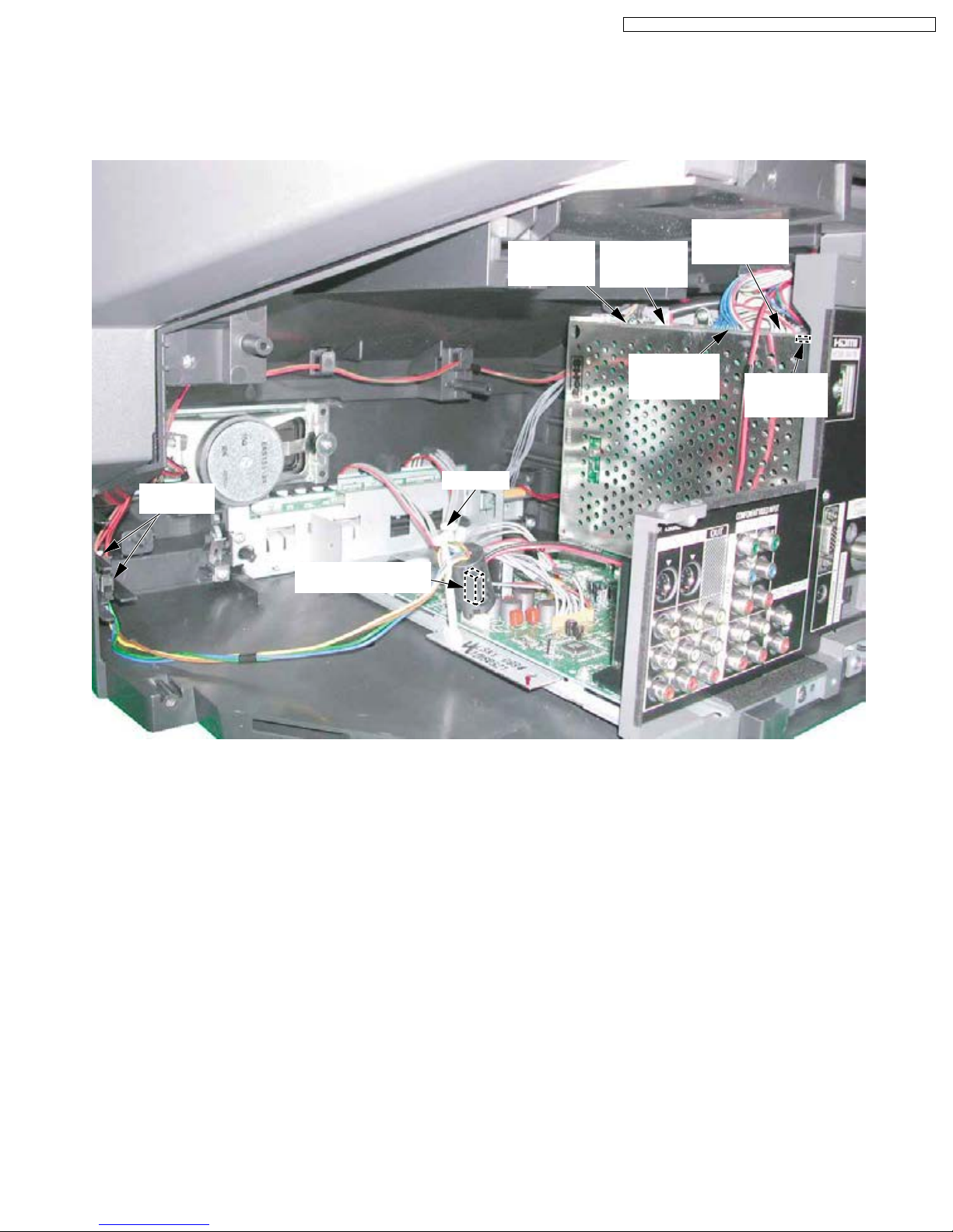
WIRE AND LEAD POSITION DIAGRAM OF THE UNIT
After servicing, make sure that all wires, leads, and clampers are placed in their original position. It is important for the best
operation of the unit.
Note: Use extreme care especially for the following.
TV Unit with Digital Tuner P.C.B.
AC Cord
Projection Unit
Base Body Unit
Fig. 9-1
16
PT-52LCX66 / PT-56LCX66 / PT-61LCX66 / PT-52LCX16 / PT-56LCX16
After servicing, make sure that all wires, leads, and clampers are placed in their original position. It is important for the best
operation of the unit.
Note: Use extreme care especially for the following.
CN6001
CN5700
(From LCD
Drive P.C.B.)
CN6008
(From LCD
Drive P.C.B.)
(From Power
Switch P.C.B.)
CN6000
(From Power
P.C.B.)
CN6002
(From Power
P.C.B.)
Speaker
Connectors
Clamper
CN4501
(From Power P.C.B.)
Fig. 9-2
17
PT-52LCX66 / PT-56LCX66 / PT-61LCX66 / PT-52LCX16 / PT-56LCX16
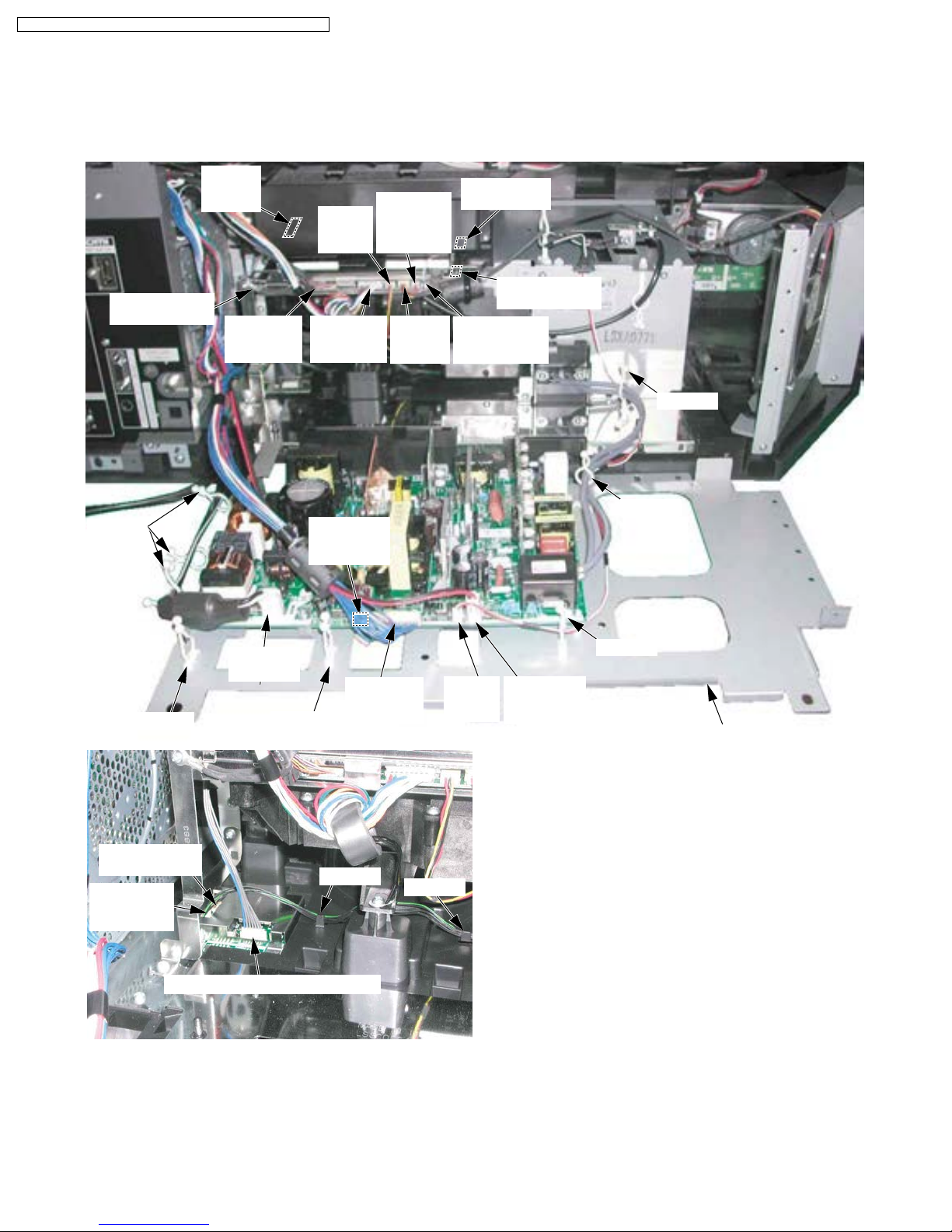
After servicing, make sure that all wires, leads, and clampers are placed in their original position. It is important for the best
operation of the unit.
Note: Use extreme care especially for the following.
GND Wire
of LVDS Cable
Clampers
CN2705
(To Iris
P.C.B.)
CN2502
(From Main
P.C.B.)
CN2702
(From
Fan 2)
CN2704
(From Main
P.C.B.)
CN1522
(From Main
P.C.B.)
CN2301
(From
Thermistor
2 P.C.B.)
CN2703
(From
Fan 3)
CN2701
(From Fan 1)
CN2303
(No connection)
CN2501
(From Cover
Switch P.C.B.)
Clamper
Clamper
Clamper
CN9501
(No connection)
CN9500
(From Hall-S
P.C.B.)
CN9502 (From LCD Drive P.C.B.)
CN1001
(AC Cord)
Clamper
CN1514
(From Main
P.C.B.)
Clamper
CN1520
(From
Thermal
Fuse)
Clamper
Clamper
CN1516
(From Base
P.C.B.)
Power PCB Mount Metal
Fig. 9-3
18
PT-52LCX66 / PT-56LCX66 / PT-61LCX66 / PT-52LCX16 / PT-56LCX16
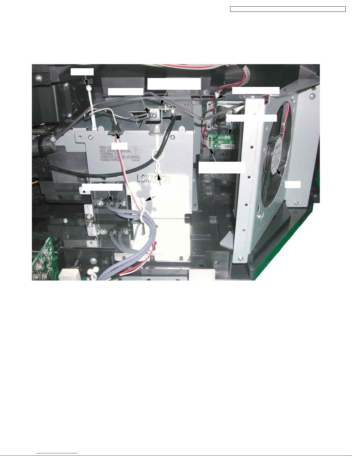
After servicing, make sure that all wires, leads, and clampers are placed in their original position. It is important for the best
operation of the unit.
Note: Use extreme care especially for the following.
Clamper
P2821
Thermal Fuse
(Thermistor 2 P.C.B.)
Speaker Connector
Power Switch P.C.B.
Hook
CN6801
(From Main P.C.B.)
Lamp Connector
Clamper
Clamper
Fig. 9-4
Fan3
19

PT-52LCX66 / PT-56LCX66 / PT-61LCX66 / PT-52LCX16 / PT-56LCX16
After servicing, make sure that all wires, leads, and clampers are placed in their original position. It is important for the best
operation of the unit.
Note: Use extreme care especially for the following.
Clampers
DT10
(From SD
Card P.C.B.)
Hook
TV Unit with Digital Tuner P.C.B.
Clamper
Clamper
Fig. 9-5
CN3901
(From Base
C.B.A.)
CN6701
(From Base
C.B.A.)
20
7 Troubleshooting Guide
7.1. Troubleshooting Hints for Block Level Repair
MAIN PARTS LOCATION
<Front View>
TEMP LED
PT-52LCX66 / PT-56LCX66 / PT-61LCX66 / PT-52LCX16 / PT-56LCX16
POWER LED
Front Cover Unit
TEMP LED
LAMP LED
Power Switch P.C.B.
Lamp Cover
Optical Cover
<Rear View>
LAMP LED
Cover Switch P.C.B.
Fan Case Unit
(Fan 1)
Projection Unit & Top Duct 3
Thermistor 2 P.C.B.
Air Filter
Thermal Fuse
Fan 3
SD Card P.C.B.
Front Jack
/Operation P.C.B.
Base P.C.B.
TV Unit & Digital Tuner P.C.B.
Digital T uner P.C.B.
Main P.C.B.
Air Filter
Air Filter
Iris P.C.B.
Note: There is not the Thermistor 1 P.C.B. in this unit.
Rear Cover
21
Fan 2
LCD Drive P.C.B.
Iris Unit
Power P.C.B.
Hall-S P.C.B.
PT-52LCX66 / PT-56LCX66 / PT-61LCX66 / PT-52LCX16 / PT-56LCX16
LED INDICATIONS FOR ERROR CONDITIONS
Each LED indication facilitates finding the cause of an error.
When an error is detected, the Lamp goes off and the LEDs on the front flash.
TEMP LED
LAMP LED
POWER LED
(Note 1, 2) (Note 3)(Note 4)
Error No.
1)
2)
3)
4)
5)
6)
7)
8)
9)
10)
11)
12)
Note:
1. The detected SOS Error 1) 2) 3) 4) 11) 12) data will be stored in the EEPROM.
2.SOS (Error) information is displayed in Service Mode (4/4).
3.LAMP OFF: The LED will flash immediately after the Lamp goes off.
4.In case of Error 9) or 10), the unit will not shut off and Dynamic Iris setting in Adv. adjust of Picture Menu will be
changed to "OFF" automatically. When the unit is turned off and turned back on, Dynamic Iris "OFF" setting remains.
Lamp LED will not flash as long as Dynamic Iris setting in Adv. adjust of Picture Menu is set to "ON" manually.
Error Information
SOS2 (Over voltage/current)
Fan 1, Fan 2 or Fan 3 stops
Abnormal voltage (DT+5V line)
IC5001 (GC4Pro) communication
error
Temperature Sensor shorted or open
(Thermistor 2 P.C.B.)
Abnormal temperature
(Thermistor 2 P.C.B.)
Clogged Air Filter
Abnormal Lamp
Iris Mechanism hardware error
Iris calibration error
Lamp Cover open
Abnormal voltage (+17V, +9V, +5V line)
for LCD Drive P.C.B.
POWER LED
flashes orange
1
2
3
5
-
-
-
-
-
-
7
8
TEMP LED
flashes red
- -
-
-
-
2
3
6
-
-
-
-
-
LAMP LED
flashes red
-
-
-
-
--
-
SOS
H10SOS2
H20FANST
H30DT9V
H50GC4PR
1
2
3
-
-
(H70LAMCV)
(H80LCDDV)
-
-
-
-
-
LAMP OFF
RESET
Power
ON/OFF
AC
ON/OFF
Power
ON/OFF
AC
ON/OFF
Power
ON/OFF
Clean
Air Filter
-
Power
-
ON/OFF
22
PT-52LCX66 / PT-56LCX66 / PT-61LCX66 / PT-52LCX16 / PT-56LCX16
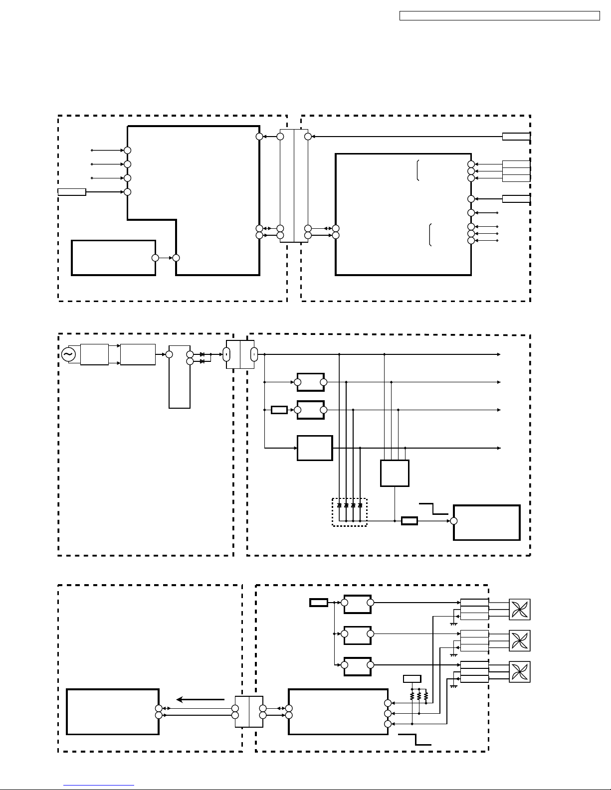
Protection Circuit
SOS terminal of IC6001 (Main microcontroller) and IC2301 (LCD Microcontroller)
IC6001 (MAIN MICROCONTROLLER)
93
108
89
CN6002-3
27
IC5001
(DIGIT AL VIDEO SIGNAL
PROCESS)
I2C SERIAL DATA0
(Error No. 11) LAMP COVER OPEN(H)
SOS2 (Error No. 1)
+5V SENS (Error No. 3)
AC STOP(L)
LAMP STATUS (Error No. 8)
I2C SERIAL DATA
I2C SERIAL CLOCK
B22
85
I2C SERIAL DATA0
(Error No. 4)
117
116
92
16 16
CN5700
19
18
CN2502
19
18
IC2301 (LCD MICROCONTROLLER)
(Error No. 2)
(Error No. 5,6) TEMPERATURE DATA1
(Error No. 7) FILTER ERROR DETECTION
35
I2C SERIAL DATA
36
I2C SERIAL CLOCK
(Error No. 12)
FAN1 LOCK(H)
FAN2 LOCK(H)
FAN3 LOCK(H)
MAIN P.C.B. LCD DRIVE P.C.B.
+17V SENS
+9V SENS
+5V SENS
CN2501-1
29
30
31
64
62
60
59
4
CN2701-3
CN2702-3
CN2703-3
CN2301-2
1) SOS2 (over voltage/current detect) detection circuit
FULL-WAVE
RECTIFIER
POWER
FACTOR
CORRECTION
T1401
1
MAIN
TRANS.
7
13
15
7
9
CN1514
9
CN6001
(+9V)
Q1102,
Q1105
SW
IC1102
+5V
1
REG
IC1103
+2.5V
1
REG
IC1100
DC-DC
CONVERTER
(Over voltage Detect)
POWER P.C.B. MAIN P.C.B.
2) Fan1, Fan2 or Fan3 stopped detection circuit
IC6001 (MAIN MICROCONTROLLER)
IC2301 (LCD MICROCONTROLLER)
+9V
DT+9V
2
2
Q1108,
Over
Q1109
IC2702
2
DRIVE
IC2703
2
DRIVE
IC2704
2
DRIVE
4
4
4
current
Detect
Q1106,
Q1107
(+7V)
(+8V)
(+7V)
SOS
SW
+3.3V
IC6001
(MAIN
MICROCONTROLLER)
Normal
93
SOS2
CN2701-1
CN2701-2
CN2701-3
CN2702-1
CN2702-2
CN2702-3
CN2703-1
CN2703-2
CN2703-3
DT+5V
SW+2.5V
SW+3.3V
FAN1
FAN2
FAN3
I2C SERIAL DATA
I2C SERIAL CLOCK
117
116
MAIN P.C.B. LCD DRIVE P.C.B.
19
18
19
18
CN5700
CN2502
I2C SERIAL
35
DATA
36
I2C SERIAL
CLOCK
23
FAN1 LOCK(H)
FAN2 LOCK(H)
FAN3 LOCK(H)
29
30
31
SOS
Normal
PT-52LCX66 / PT-56LCX66 / PT-61LCX66 / PT-52LCX16 / PT-56LCX16
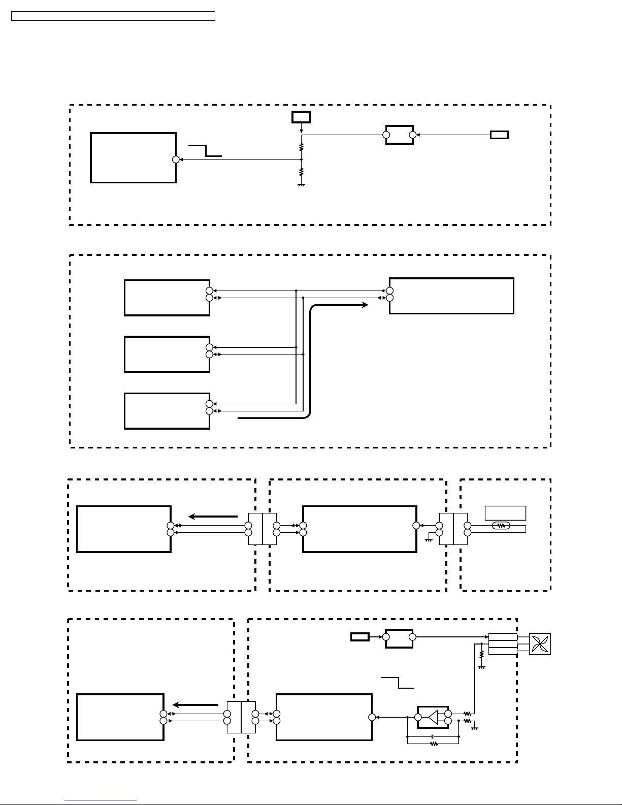
3) Abnormal voltage (DT+5V line) detection circuit
DT+5V
IC6001 (MAIN MICROCONTROLLER)
Normal
+5V SENS
108
SOS
SOS: 0V on DT+5V line
MAIN P.C.B.
4) IC5001 (GC4PRO) communication error detection circuit
IC5000
(MAIN VIDEO SIGNAL PROCESS)
I2C SERIAL CLOCK0
I2C SERIAL DATA0
IC5801
(HDMI INTERFACE)
I2C SERIAL CLOCK0
I2C SERIAL DATA0
IC5001
(DIGITAL VIDEO SIGNAL PROCESS)
I2C SERIAL CLOCK0
I2C SERIAL DATA0
A23
B22
82
81
acknowledge
28
27
IC1102
+5V
2
1
REG
IC6001 (MAIN MICROCONTROLLER)
84
I2C SERIAL CLOCK0
85
I2C SERIAL DATA0
SOS: No acknowledge reply
+9V
MAIN P.C.B.
5, 6) Temperature Sensor error (shorted, open, or abnormal) detection circuit
IC6001 (MAIN MICROCONTROLLER)
I2C SERIAL DATA
I2C SERIAL CLOCK
117
116
19
18
CN5700
CN2502
IC2301 (LCD MICROCONTROLLER)
I2C SERIAL
35
19
18
DATA
36
I2C SERIAL
CLOCK
TEMPERATURE
DATA1
64
MAIN P.C.B. LCD DRIVE P.C.B.
7) Clogged air filter detection circuit
IC2702
4
2
DRIVE
SOS
Normal
IC2705
62
1
IC6001 (MAIN MICROCONTROLLER)
I2C SERIAL DATA
I2C SERIAL CLOCK
61
61
19
18
19
18
CN5700
CN2502
+9V
IC2301 (LCD MICROCONTROLLER)
I2C SERIAL
35
DATA
36
I2C SERIAL
CLOCK
FILTER ERROR
DETECTION
2
1
3
2
R2821
TEMPERATURE
SENSOR
2
1
CN2301
P2821
THERMISTOR 2
CN2701-1
CN2701-2
CN2701-3
P.C.B.
FAN1
MAIN P.C.B. LCD DRIVE P.C.B.
24
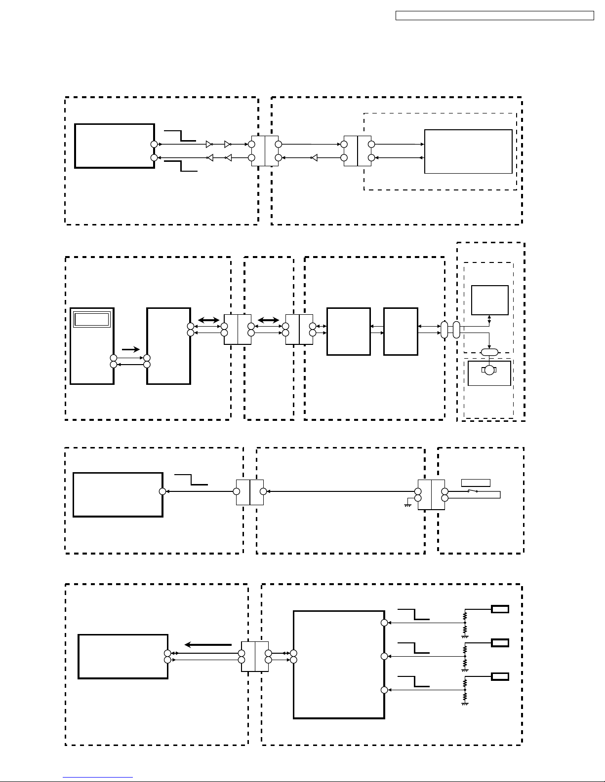
8) Abnormal Lamp detection circuit
IC6001
(MAIN MICROCONTROLLER)
ON
OFF
Q6012
LAMP ON(H)
LAMP STATUS
18
27
SOS Normal
SOS: Lamp does not light up
Normal: Lamp ON
Q6011
Q6001 Q6000
1 1
3 3
CN6002
CN1522
Q1602
16
13
LAMP ON(H)
16
13
CN1401
LAMP STATUS
(ON(H)/OFF (L))
POWER P.C.B.MAIN P.C.B.
PT-52LCX66 / PT-56LCX66 / PT-61LCX66 / PT-52LCX16 / PT-56LCX16
POWER CONTROL
CIRCUIT 2
9), 10) Iris Mechanism hardware error/Iris calibration error detection circuit
IC5001
(DIGITAL SIGNAL
PROCESS)
GC4PRO
I2C SERIAL
I2C SERIAL
DATA
CLOCK
B22
A23
IC6001
(MAIN
MICROCONTROLLER)
I2C SERIAL
I2C SERIAL
I2C SERIAL
85
DATA
84
I2C SERIAL
CLOCK
DATA
CLOCK
117
116
19
18
19
18
CN5700
CN2502
5
4
5
4
CN2705
CN9502
IC9502
IRIS
MICROCONTROLLER
IC9500,
IC9501,
ETC
IRIS
CONTROL
LCD DRIVE
MAIN P.C.B.
P.C.B.
IRIS P.C.B.
11) Lamp cover open detection circuit
IC6001 (MAIN MICROCONTROLLER)
NormalSOS
LAMP COVER OPEN(H)
92
16 16
CN5700
CN2502
CN9500
1
2
CN2501
1
2
P2912
CN9700
SW2911
COVER SW
IRIS UNIT
HALL-S
P.C.B.
HALL
ELEMENT
CN9701
M
IRIS MOTOR
IRIS
MECHANISM
UNIT
MAIN P.C.B. LCD DRIVE P.C.B.
12) Abnormal voltage (+17V, +9V, +5V lines) detection circuit
IC6001 (MAIN MICROCONTROLLER)
I2C SERIAL DATA
I2C SERIAL CLOCK
117
116
MAIN P.C.B. LCD DRIVE P.C.B.
19
18
19
18
CN5700
CN2502
IC2301
(LCD MICROCONTROLLER)
+17V SENS
I2C SERIAL
35
DATA
36
I2C SERIAL
CLOCK
+9V SENS
+5V SENS
25
COVER SWITCH
P.C.B.
Normal
60
59
4
SOS
Normal
SOS
Normal
SOS
+17V
+9V
+5V
 Loading...