

Panasonic pt51hx41e, pt51hx41ce, pt56hx41e, pt56hx41ce, pt61hx41e Diagram
...
ORDER NO. MTNC010417C1
B2
Service Manual
HDTV MONITOR
Main Manual
(P5P)
Panasonic
Models
Chassis
PT-51HX41E AP820
PT-51HX41CE AP820
PT-56HX41E AP820
PT-56HX41CE AP820
PT-61HX41E AP820
PT-61HX41CE AP820
This Service manual is issued as a service guide for the models of the P5P family listed above. Included in this manual
are a set of schematics, alignment procedures, disassembly procedures and a complete parts list.
“WARNING! This Service Manu al is des igned for ex perienced re pair techni cians only and is n ot designed for use by the general public.
It does not contain warnings or cautions to advise non-technical individuals of potential dangers in attempting to service a product.
Products powered by electricity should be se rviced or repaired only by experienced profess ional technicians. Any attem pt to
service or repair the product or products dealt with in this Service Manual by anyone else could result in serious injury or death.”
The service technician is required to read and follow the “Safety Precautions” and “Important Safety Notice” in the Ma in Ma nual.
Copyright 2001 by Matsushita Elec tric Corporati on of
America. All rights reserved. Unauthorized copying
®
and distribution is a violation of law.
Important Safety Notice
Special components a re used in this projection tel evision which are important for safety. These components are
identified on the schematic diagram by the symbol and printed in BOLD TYPE on the replacement part list. It is
essential that these c ritical parts are replaced with the manu facturer ’s spe cified replac ement par t to prevent x -ray
radiation, shock, fire or other hazards. Do not modify the original design without the manufacturer’s permission.
Safety Precautions
General Guidelines
An
isolation transformer
during the servicing of a PTV whose chassis is not
isolated from AC power line. Use a transformer of
adequate power rating a s this protects the techn ician
from accidents resulting in personal injury from
electrical shocks. It will also p rotect the PTV from being
damaged by accidental shorting that may occur
during servicing.
When servicing, observe the original lead dress,
especially in the high voltage circuit. Replace all
damaged parts (also parts that show signs of
overheating.)
Always replace protective devices, such as
fishpaper, isolation resistors and capacitors, and
shields after servicing the PTV. Use only
manufacturer ’s recommended rating for fuses, circu its
breakers, etc.
High potentials, as high as 32.5kV, are present when
this PTV is operating. Ope rat io n of the PTV without the
rear cover introduces danger for electrical shock.
Servicing should not be performed by anyone who is
not thoroughly familiar wit h the necessary precautions
when servicing high-voltage equipment.
Extreme care should be practic ed when handling the
picture tube
due to atmospheric pressure. (14.7 lbs. per sq. in.). Do
not nick or scratch the glass or subject it to any undu e
pressure. When handling, use safety goggles and
heavy gloves for protection. Discharge the picture
tube by shorting the anode to chassis ground (not to
the cabinet or to other mounting hardware). When
discharging connect cold ground (i.e. DAG ground
lead) to the anode wi th a well insulated wir e or use a
grounding probe.
. Rough handling may caus e it to implod e
should always be used
X-ray Precautions
The front area (between the projection tube and the
lens) is enclosed by a metal box to ensure positive
safety during normal and abnormal conditions when
checking and repairing. To fully ensure safety, the
following precautions must be observed.
1. Do not remove the lens or metal box.
2. Make sure to turn the power OFF when the le ns is
removed or when checkin g the cleanliness of the
lens.
3. Do not remove the lens or metal box to check the
projection tube for operation by w atching it directly.
Use a mirror or paper to view the image.
Before returning a se rviced PTV to the owner, the
service technician must thoroughly test the unit to
ensure that is completely safe to operate. Do not use a
line isolation transformer when testing.
Leakage Current Cold Check
Unplug the AC cord and connect a jumper between the
two plug prongs. Press the POW ER swit ch ON.
Measure the resistance between the jumpered AC plug
and expose metallic parts such as screw heads,
Service Manual
antenna terminals, control shafts, etc. If the exposed
metallic part has a return path to the chassis, the
reading should be between 240kΩ and 5.2MΩ. If the
exposed metall ic part does not have a re turn path to
the chassis, the re adi ng sh oul d be infinite.
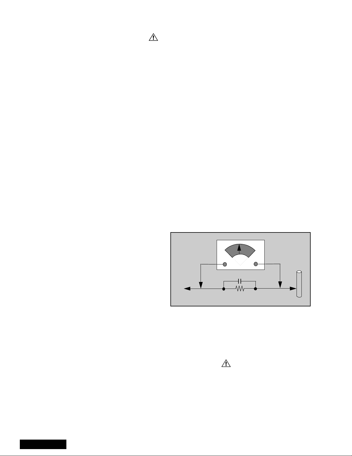
Leakage Current Hot Check (See Figure 1)
Plug the AC cord directly into the AC outlet. Do not use
an isolation transformer during the check.
Connect a 1.5kΩ 10 watt resistor in parallel with a
0.15µF capacitor between and exposed metallic part
and ground. Use earth ground, for example a
water pipe.
Using a DVM with a 1000 ohms/volt sensitivity or
higher, measure the AC potential across the resistor.
Repeat the procedure and measure the voltage
present with all other expose metallic parts.
Verify any potential does not exceed 0.75 vo lt RMS. A
leakage current tester (such a Simpson Model 229,
Sencore Model PR57 or equivalent) may be used in
the above procedure, in which case any current
measure must not exceed 0.5 milliamp. If any
measurement is out of the specified limits, there is a
possibility of a shock hazard and the PTV must be
repaired and rechecked before it is returned to
the customer.
AC VOLTMETER
COLD
WATER
PIPE
(GROUND)
0.15µF
TO INSTRUMENT’S
EXPOSED METAL
PARTS
Figure 1. Hot Check Circuit
1500Ω,10W
Insulation Test
Connect an insulation tester between an exposed
metallic part and AC line.
Apply 1080VAC/60Hz for 1 second. Confirm that the
current measurement is 0.5mA ~ 2.0mA. Repeat test
with other metallic exposed parts.
X-ray Radiation
WARNING: The potential source of X-ray radiation in the
PTV is in the high voltage section and the picture tube.
Note: It is important to use an accurate, calibrated
high voltage meter.
Set brightness, picture, sharpness and color
controls to Minimum.
Measure the High Voltage. The high should be
31.5kV ± 1.0kV. If the upper limit is out of tolerance,
immediate servic e and correction is requ ired to insure
safe operation and to prevent the possibility of
premature component failure .
- 2 -
Important Safety Tests
Measuring H.V.
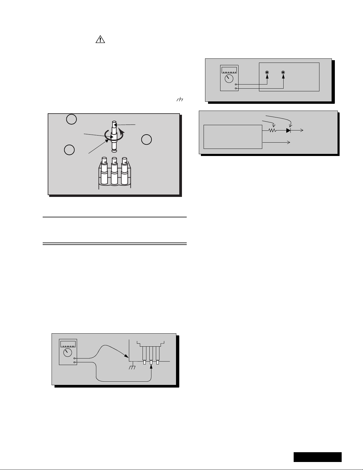
The anode caps are cemented to the CRTs. To gain
access for high vo ltage measurem ent, remove the re d
CRT’s anode lead from the flyback transformer
distributor. Grasp the anode lead protective cap at its
bottom and squeeze it against the locking cap body
inside, Rotate 1/4 turn count er clockwise and pull the
anode lead sleeve out of the FBT distributor. Connect a
high voltage lead (+) from your H.V. meter to the FBT
distributor, and the common (-) to cold ground ( ).
(See Figure 2).
1
Grasp protective
Anode lead
rubber cap
3
2
Push & rotate
Discharge to
CRT Chassis
cap counterclockwise
to remove
FBT Distributor
Figure 2. Removal of FBT leads
Note: Reinsert the anode lead into the FBT
distributor until it is tightly and fully seated.
T urn the locking cap clockwise to lock in place.
(EHT) Protector Operation Check
With the cabinet ba ck removed, apply a n ominal 120V
AC to the PTV.
Over Voltage Test
Preparation:
1. Turn PTV “OFF”
2. Connect an NTSC signal generator to the
antenna terminal.
3. Connect DVM (+) TPD50 and (-) TPD51 on
D Board. (See Figure 4)
4. Connect a H.V. meter (static type, class 0.1 ) with
high voltage leads to high voltage distributor
on FBT. (See Figure 4)
TPD51 TPD50
-
+
D-Board
DVM
D-Board
IC802 PIN 2
OR TPD8
Variable
Power
Supply
MA150
100Ω 1/2 W
(+)
(15~25DC)
(-)
HEAT SINK OF Q551
Figure 4. DVM & Power supply connection.
5. Connect the 15 ~ 25 V DC variable power supply to
(+) TPD8 or IC802 pin 2 (D-Board) and (-) heat
sink of Q551 (See Figure 4).
Procedures:
1. Apply a monoscope pattern.
2. Turn PTV ON.
3. Adjust the Picture or Brightness controls so that the
DVM reads 16.5 volts ± 0.5 volts.
4. Increase the variabl e power supply until set turns
off. The set should turn off at 16.5 volts ± 0.5 volts
(DVM) and high voltage le ss th an 3 6.4k V.
5. If the DVM reading is other than 16.5 volts (± 0.5
volts), readjust picture or brightness control and
repeat steps 3.
6. Turn off the variable supply and confirm that the set
will turn on with the Remote Control.
-
+
H.V. METER
Cold Ground
FBT Distributor
CRT
CHASSIS
Figure 3. Measuring H.V.
- 3 -
Service Manual

Important Safety Notice. . . . . . . . . . . . . . . . . . . 2
Safety Precautions . . . . . . . . . . . . . . . . . . . . . . . . 2
General Guidelines . . . . . . . . . . . . . . . . . 2
X-ray Precautions . . . . . . . . . . . . . . . . . . 2
Leakage Current Cold Check . . . . . . . . . 2
Leakage Current Hot Check . . . . . . . . . . 2
Insulation Test . . . . . . . . . . . . . . . . . . . . . 2
X-ray Radiation . . . . . . . . . . . . . . . . . . . . 2
Important Safety Tests. . . . . . . . . . . . . . . . . . . . 3
Measuring H.V. . . . . . . . . . . . . . . . . . . . . 3
(EHT) Protector Operation Check . . . . . . 3
Service Notes . . . . . . . . . . . . . . . . . . . . . . . . . . . 5
Leadless Chip Component
(surface mount). . . . . . . . . . . . . . . . . 5
Component Removal. . . . . . . . . . . . . . . . 5
Chip Component Installation . . . . . . . . . . 5
How to Replace Flat-IC . . . . . . . . . . . . . . 5
Feature Table . . . . . . . . . . . . . . . . . . . . . . . . . . . 6
Boards Designation . . . . . . . . . . . . . . . . . . . . . . 7
PTV - Location of Controls . . . . . . . . . . . . . . . . 8
Quick Reference Control Operation . . . . 8
Remote - Location of Controls . . . . . . . . . . . . . 9
Serviceman Mode (Electronic Controls) . . . . 25
Quick Entry to Serviceman Mode:. . . . . 25
To toggle between Aging
and Serviceman modes . . . . . . . . . 25
Exiting the Serviceman Mode:. . . . . . . . 25
To Check Purity: . . . . . . . . . . . . . . . . . . 25
Instructional Flow Cha rt
for Serviceman Mode . . . . . . . . . . . 28
HV_Feedback Voltage. . . . . . . . . . . . . . 30
Bright Adjustment (BRIGHT) . . . . . . . . . 30
Sub-Contrast (CONT), Sub-Bright
(FINAL) Adjustment. . . . . . . . . . . . . 30
Tint Adjustment (TINT) . . . . . . . . . . . . . 30
Red, Green & Blue Screen Cutoff . . . . . 31
White Balance Adjustment . . . . . . . . . . 31
Tint and Color Check. . . . . . . . . . . . . . . 31
MTS Circuit Adjustments. . . . . . . . . . . . 31
Input Level Adjustment (MTSIN) . . . . . . 31
Stereo Separation Adjustment
(SEP AL & SEPAH) . . . . . . . . . . . . . 31
Clock Adjustment (CLOCK). . . . . . . . . . 32
Audio Signal Path Block Diagram. . . . . . . . . . 33
Video-Chroma Signal Path Block Diagram . . 34
IIC Connection . . . . . . . . . . . . . . . . . . . . . . . . . 35
Description of Connectors . . . . . . . . . . . . . . . 36
Parts List . . . . . . . . . . . . . . . . . . . . . . . . . . . . . . 38
Chassis & Boards Layout . . . . . . . . . . . . . . . . 10
Board Description . . . . . . . . . . . . . . . . . 10
Disassembly for Service . . . . . . . . . . . . . . . . . 11
Speaker Grill Removal. . . . . . . . . . . . . . 11
Keyboard Removal . . . . . . . . . . . . . . . . 11
Speakers Replacement . . . . . . . . . . . . . 11
Cabinet Back Lower Removal. . . . . . . . 11
Cabinet Back Cover Removal . . . . . . . . 11
Cabinet Front Removal . . . . . . . . . . . . . 12
Screen Assembly. . . . . . . . . . . . . . . . . . 12
Main Chassis Block. . . . . . . . . . . . . . . . 12
Disassembly for CRT Replacement . . . 13
X-RAYS SHIELD . . . . . . . . . . . . . . . . . . 13
CRT Replacement . . . . . . . . . . . . . . . . 13
Optical Block Position Adjustment. . . . . 14
PTV Screen Assemblies . . . . . . . . . . . . 15
B+ Voltages Table . . . . . . . . . . . . . . . . . 15
CRT Set Up . . . . . . . . . . . . . . . . . . . . . . . . . . . . 16
Dynamic Focus Adjustments. . . . . . . . . 16
Electrical Adjustment. . . . . . . . . . . . . . . 16
Focus - Optical Lens Adjustment. . . . . . 17
Optical Adjustments. . . . . . . . . . . . . . . . 17
Electric & VM Focus Adjustment,
Complete adjustment . . . . . . . . . . .17
Vertical Size Adjustment (VSIZE) . . . . . 18
Horizontal Phase Adjustment (H-POS) . 18
Trapezoid Adjustment (EWTRA) . . . . . . 18
Pincushion Adjustment (PC C). . . . . . . .19
Centering Magnets Adjustment . . . . . . . 19
Horizontal Size Adjustment (H WID) . . . 19
Convergence Adjustment . . . . . . . . . . .19
Coarse Adjustment Mode (COARSE) . . 20
Fine Adjustment Mode (FINE). . . . . . . .22
Horizontal and Vertical Size Check . . . . 24
Convergence Alignment Template. . . . . 24
D-Board layout . . . . . . . . . . . . . . . . . . . . . . . . . . 49
D-Board schematic (left portion). . . . . . . . . . . . . 50
D-Board schematic (right portion). . . . . . . . . . . . 51
A-Board schematic (left portion) . . . . . . . . . . . . . 52
A-Board schematic (left middle) . . . . . . . . . . . . . 53
A-Board schematic (right middle) . . . . . . . . . . . . 54
A-Board schematic (right portion). . . . . . . . . . . . 55
DH-Board schematic . . . . . . . . . . . . . . . . . . . . . 56
K, G & R-Board schematics & layouts . . . . . . . . 57
LR-Board schematic, layout & voltages . . . . . . . 58
LB-Board schematic, layout & voltages . . . . . . . 59
LG-Board schematic, layout & voltages . . . . . . . 60
A & D-Board voltages. . . . . . . . . . . . . . . . . . . . .61
Waveforms . . . . . . . . . . . . . . . . . . . . . . . . . . . . . 62
Service Manual
- 4 -

Service Notes
Note: These components are affixed with glue. Be careful not to break or damage any foil under the
component or at the pins of the ICs when removing. Usually applying heat to the component for
a short time while twisting with tweezers will break the component loose.
Leadless Chip Component
(surface mount)
Chip components must be replaced with identical chips
due to critical foil track sp acing. There are no holes in
the board to mount standard transistors or diodes.
Some chip capacitor or resistor board solder pads may
have holes through the board, however the hole
diameter limits standard resistor replacement to 1/8
watt. Standard capacitor may also be limited for the
same reason. It is recommended that identical
components be used.
Chip resistor have a three digit numerical resistance
code - 1st and 2nd significant digits and a multiplier.
Example: 162 = 1600 or 1.6kΩ resistor, 0 = 0 Ω (jumper).
Chip capacitors generally do not have the value
indicated on the capacitor. The color on the component
indicates the general range of the capa ci tan ce .
Chip transistors are identified by a two letter code . The
first letter indica ted the type an d the second letter, the
grade of transistor.
Chip diodes have a two lette r i den tif ic ati on code as per
the code chart and are a dual diode pack with either
common anode or comm on cathode. Check the parts
list for correct di ode num ber.
Component Removal
1. Use solder wick to remove s older fr om compo nent
end caps or termin al.
2. Without pulling up, carefully twist the component
with tweezers to break the adhesive.
3. Do not reuse removed leadless or chip
components since they are subject to stress
fracture during removal.
Chip Component Installation
1. Put a small amount of solder on the board
soldering pads.
2. Hold the chip component against the soldering
pads with tweezers or with a miniature alligator clip
and apply heat to the pad area with a 30 watts iron
until solder flows. Do not appl y heat for more than
3 seconds.
TYPE
Chip Components
GRADE
c
c
SOLDER
CAPS
How to Replace Flat-IC
- Required Tools -
• Soldering iron • De-solder braids
• Sharp pliers (wire
cutters and long nose)
1. Cut the pins of the defective IC with the wire cutter
pliers, and remove it completely away from the
board. If the IC is g lued to the b oard, apply h ot air
to complete the remova l. CAUTION- Do not pull or
twist the pliers, i t may damage the soldering pads
in the board.
Flat-IC
2. Using the Soldering Iron and the lo ng nose pliers,
remove the IC pins that are still attached to the
board.
3. Using the De-solde r braid and the Soldering Iron ,
remove the solder from the board soldering pads.
4. Position the new Flat-IC in pl ace (apply the pins of
the Flat-IC to the soldering pads where the pins
need to be soldered). Properly determine the
positions of the soldering pads and pins by
correctly aligning the polarity symbol. St ar t alig ning
and soldering Pin No .1, then align and solder th e
pin in the apposite corner of the IC, this will help to
align the rest of the pins.
Polarity
Symbol
• Magnifier
Soldering
Iron
De-Solder
Braid
Soldering
Iron
b
b
ANODES
MH DIODE
e
e
TRANSISTOR
COMMON
CATHODE
SOLDER
CAPS
CAPACITOR
1ST DIGIT
RESISTOR
2ND DIGIT
MULTIPLIER
=1600 = 1.6k
5. Solder all pins to the soldering pads using a fine
tipped soldering iro n.
Solder
Soldering
Iron
6. Check with a magnifier fo r solder bridge between
the pins or for dry joint between pins and soldering
pads. To remove a solder brid ge, use a de-solder
braid as shown in the figure below.
De-Solder
Braid
- 5 -
Solder
Bridge
Service Manual
Soldering
Iron

Service Notes (Continued)
IMPORTANT: To protect against possible damage to
the solid state devices due to arcing or static
discharge, make cer tain that all ground wi res an d CRT
DAG wire are secu re ly conne cted.
CAUTION: The power supply circuit is above earth
ground and the chassis cannot be polarized. Use an
isolation transformer when s ervicing the PTV to avoid
damage to the test equipment or to the chassis.
Connect the test equipment to the proper ground (( )
or ( )) when servicing, or incorrect voltages will
be measured.
WARNING: This PTV has been designed to meet or
exceed applicable safety and X-ray radiation protection
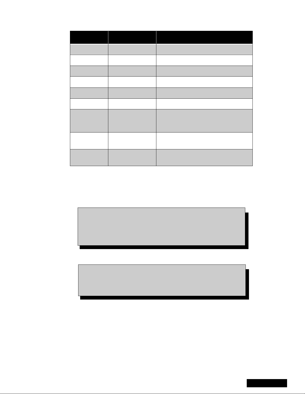
Feature Table
as specified by gover nment a gencies and ind ependen t
testing laboratories.
To maintain original product safety design standards
relative to X-ray radiation and shock and f ire hazard,
parts indicated with th e symbol on the schematic
must be replaced with identical parts. Order parts from
the manufacturer’s parts center using the parts
numbers listed in this service manual, or provide the
chassis number and the part reference number.
For optimum performance and readability, all other
parts should be replaced with components of
identical specification.
PT-51HX41E/CE
FEATURE
PT-56HX41E/CE
PT-61HX41E/CE
Chassis P5P
Tunning system 256K
# of channels 181
Menu language Eng/Span/Fr
Closed Caption (CC) X
V-Chip (USA/CANADA) X
Picture In Picture (PIP) 2T split
VIDEO INPUT MEMORY/SKIP SKIP
2RF X
Remote control # EUR7603Z20
Screen protector X
Comb filter 3D Y/C
COLOR TEMP X
NEW YNR X
VM X
V/A norm Both
DIGITAL SCAN RATE 1080i, 480p
NTSC LINE-DOUBLER 480i
MTS/SAP/DBX X
Bass/Bl/Treb control X
AI sound X
SURROUND X
Spatializer/BBE BBE
Built-in audio power 15W/CH (10%)
# of speakers 2
A/V in (rear/front) 4 (3/1)
S-VHS in (rear/front) 2/1
Audio out Fixed & Variable
PT-51HX41E/CE
FEATURE
PT-56HX41E/CE
PT-61HX41E/CE
COMPONENT INPUT (Y, Pb, Pr) 2
DOLBY CENTER CHANNEL IN X
51” Dimensions mm
WxDxH in
51” Weight (kg/lbs) 90/198.4
56” Dimensions mm
WxDxH in
56” Weight (kg/lbs) 111.5/245.8
61” Dimensions mm
WxDxH in
61” Weight (kg/lbs) 117.5/259.0
Power source (V/Hz) 120V 60Hz
Anode voltage 31.5kV ± 1.0kV
Video input jack
Audio input jack 500mV RMS 47kΩ
1137x653x1361.0
44.8x25.7x53.6
1197x685x1418
47.1x27.0x55.8
1316x708x1516
51.8x27.9x59.7
1Vp-p 75Ω, phono
jack
Table 1: Feature Table (Continued)
Specifications are subj ec t to c hange
without notice or obl ig ati on.
Dimensions and weights are
approximate.
Service Manual
Table 1: Feature Table
- 6 -
Boards Designation
BOARD PART NUMBER BOARD DESCRIPTION
G-BOARD TNP2AA088 FRONT A/V INPUTS
K-BOARD TNP2AA087 KEYBOARD
R-BOARD TNPA0615AB IR S ENSOR
LR-BOARD TNPA1810 RED DRIVER
LG-BOARD TNPA1811 GREEN DRIVER
LB-BOARD TNPA1812 BLUE DRIVER
MAIN CHASSIS , VIDEO PROCESSI NG,
A-BOARD TNPH0370
CONVERGENCE, AUDIO
PROCESSING
DH-BOARD TNPA2033
D-BOARD TNPH0371
Table 2: Boards Designation
Note: The A-Board (
Non-Serviceable. Except for A-Board both Tuners, IC2302,
IC7001, IC7002 and IC870. If any of these components or
boards is defective r eplea ce it with a n ew on e and take bac k the
defective board to the service center.
Notice: When ordering any Board, add and ” S” after the Board
TNPH0370S
suffix applic ati on.
PIP PROCESSING, SPLIT, SEARCH,
FORMATS
POWER SUPPLY, VERTICAL OUT,
HORIZONTAL OUT
) and DH-Board (
TNPA2033S)
are
Example: If Order A-Board, should be ordered as:
- 7 -
TNPH0370
S.
Service Manual
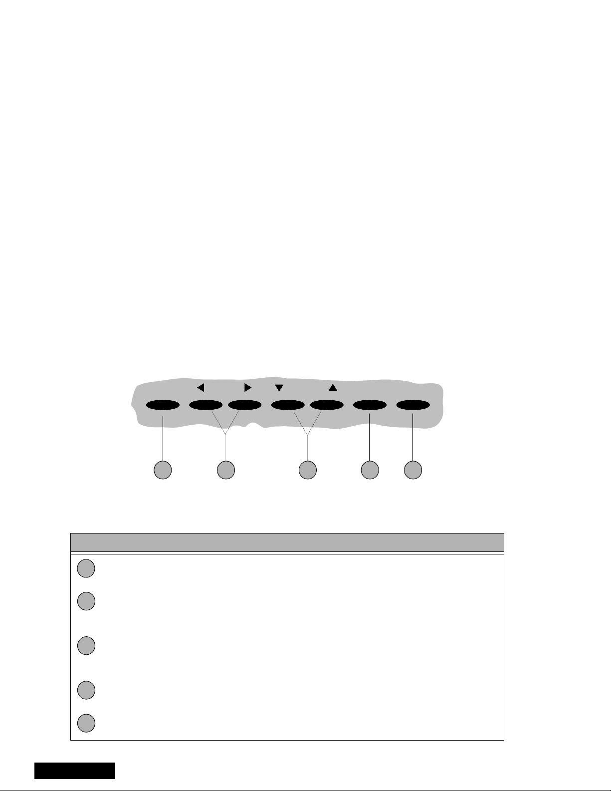
PTV - Location of Controls
POWER VOLUME CHANNEL ACTION TV/VIDEO
1 2 4 53
Figure 5. Location of Controls PTV
Quick Reference Control Operation
Quick Reference Control Operation
1
2
3
Power - Press to turn ON or OFF.
Volume - Press to adjust Sound Level, or to adjust Audio Men us, Video Menus, and
select operating features when menus are displayed
Channel - Press to s elect programm ed channels. Pr ess to highlight desired features
when menus are displayed. Also use to select Cable Converter box channels after
programming Remote Control Infra-red codes (the TV/AUX/CABLE switch must be set
in CABLE position).
4
5
Service Manual
Action - Press to displ ay Main Menu and access On Screen f eature and Ad justment
Menus.
TV/Video - Press to select TV or one of the Video Inputs, for the Main Picture or the
PIP frame (when PIP frame is displayed).
- 8 -
Remote - Location of Controls
POWER Button
Press to turn ON and OFF.
MUTE Button
Press to mute sound.
A second press resumes sound.
Press also to access and delete
Closed Caption display.
TV, VCR, DVD, CBS/CBL
Component function buttons
VOL (volume) Buttons
Press to adjust TV sound level.
Use with Channel buttons to
navigate in menus.
R-TUNE (Rapid Tune) Button.
Press to switch to the previous
channel.
ACTION Button
Press to display Main Men u and access or
exit On Screen features
and Adjustment Menus.
REW, PLAY, FF, TV/VCR, STOP, PAUSE,
REC & VCR CHANNEL Buttons
Component function buttons.
DBS EXIT& DBS GUIDE Buttons
DBS function buttons.
LIGHT Button
Press to light remote control buttons.
SAP
Access second audio program
ASPECT
Select picture size (ratio) to match
programming format
MOVE, PIP, SPLIT/SIZE, FREEZE, SWAP ,
SEARCH, PIP CHANNEL
PIP function buttons
Figure 6. Location of Controls (EUR7603Z20 Remote)
For additional information for this rem ote please refer
to the Remote Guide, listed on the parts li st.
- 9 -
Service Manual
Chassis & Bo ar ds Layout
DH
A
B
Front Corner View
LR
Back View
Figure 7. Chassis & Boards Layout.
Board Description
A Main Chassis , Video Processing, Co nvergence,
Audio Processing
D Power Supply, Vertical Out, Horizontal Out
DH PIP Processing, Split, Search, Formats
LG
LB Blue CRT Output
LG Green CRT Output
LR Red CRT Output
R IR Sensor
R
LB
Service Manual
- 10 -
Disassembly for Service
Note:
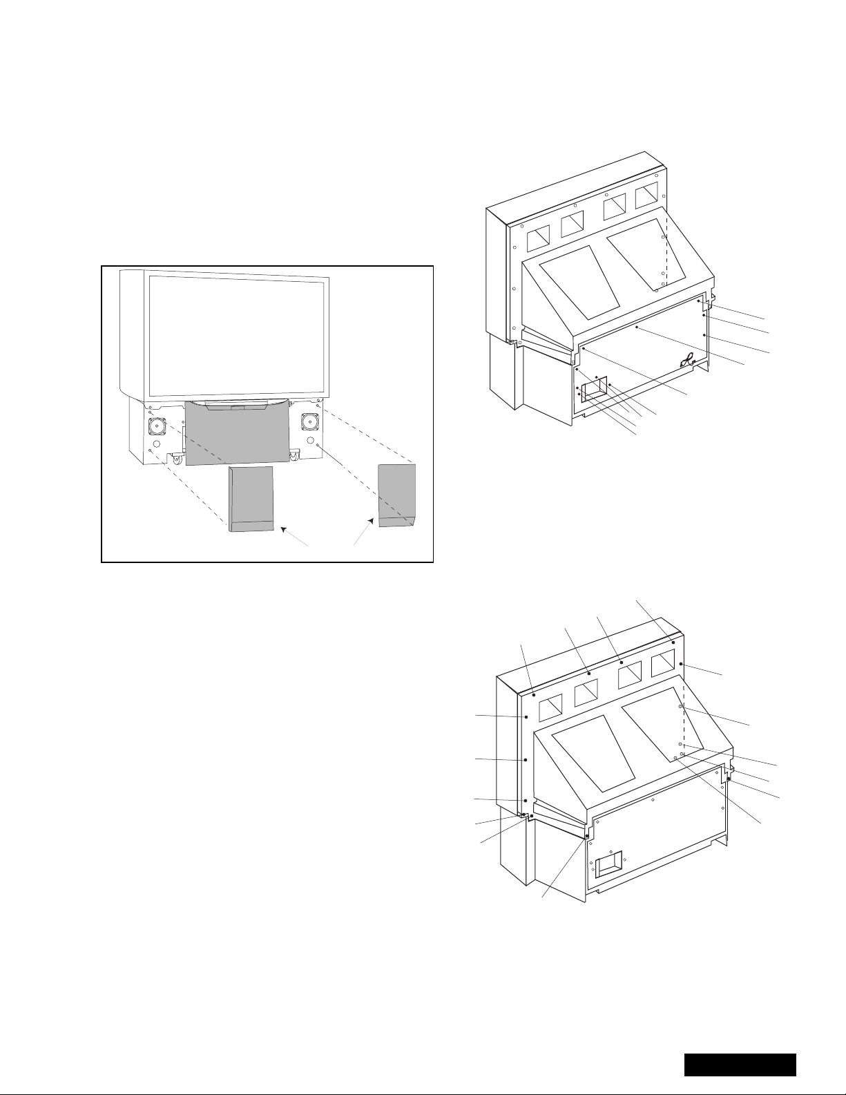
Speaker Grille Removal
(Figure 8 .)
1. The 2 Speaker Grilles are se cured to the wooden
2. The Center Front Cover is secured by 4 screws.
Keyboard Removal (7-Key Button)
(Figure 8 )
1. Remove the Speaker Grill. (see Figure 8)
2. Unplug the cables (2) from the Keyboard
Speakers Replacement
1. Remove the speaker s grill. (see Figure 8)
2. Each speaker set is s ec ur ed t o th e c abi net wit h ( 4)
3. Disconnect the R & L speaker lead connectors
Board ground wires may have to b e discon nected to dis assembl e some board s. Al l ground w ires must b e
reconnected using jumper leads, if necessary, before power is applied to PTV for service.
base of PTV. Grip each panel from the sides and
botton part, gently pull forward to remove. When
reassembling, make certain to firmly press on the
panel where the insertion points (4) are located,
one on each corner.
Panasonic
Front Cover
Speaker Grill
Figure 8. Speaker Grill Remova l.
assembly. Remove the 2 screws from the left and
right sides of Keyboard assembly. Tilt the
Keyboard assembly upward and release it from the
screen frame assembly.
screws.
from the speaker units.
2. Remove (3) screws from ar ound the A/V terminal
board (marked with arrows).
Figure 9. Lower Cabinet Back Removal
Cabinet Back Cover Removal
(Figure 10)
1. First remove the Cabinet Back Lower Cover.
2. The top back cover is secured with (16) screws
around its perimeter (See Figure 10 for screws
location).
3. Be careful not to damage the mirror attached to the
underside of cover.
Cabinet Back Lower Removal
(Figure 9 )
1. Remove (7) hex screws around its perimeter
marked with arrows. (See Figure 9 for screw
location).
- 11 -
Figure 10. Cabinet Back Cover Removal
Service Manual
Disassembly for Service (Continued)
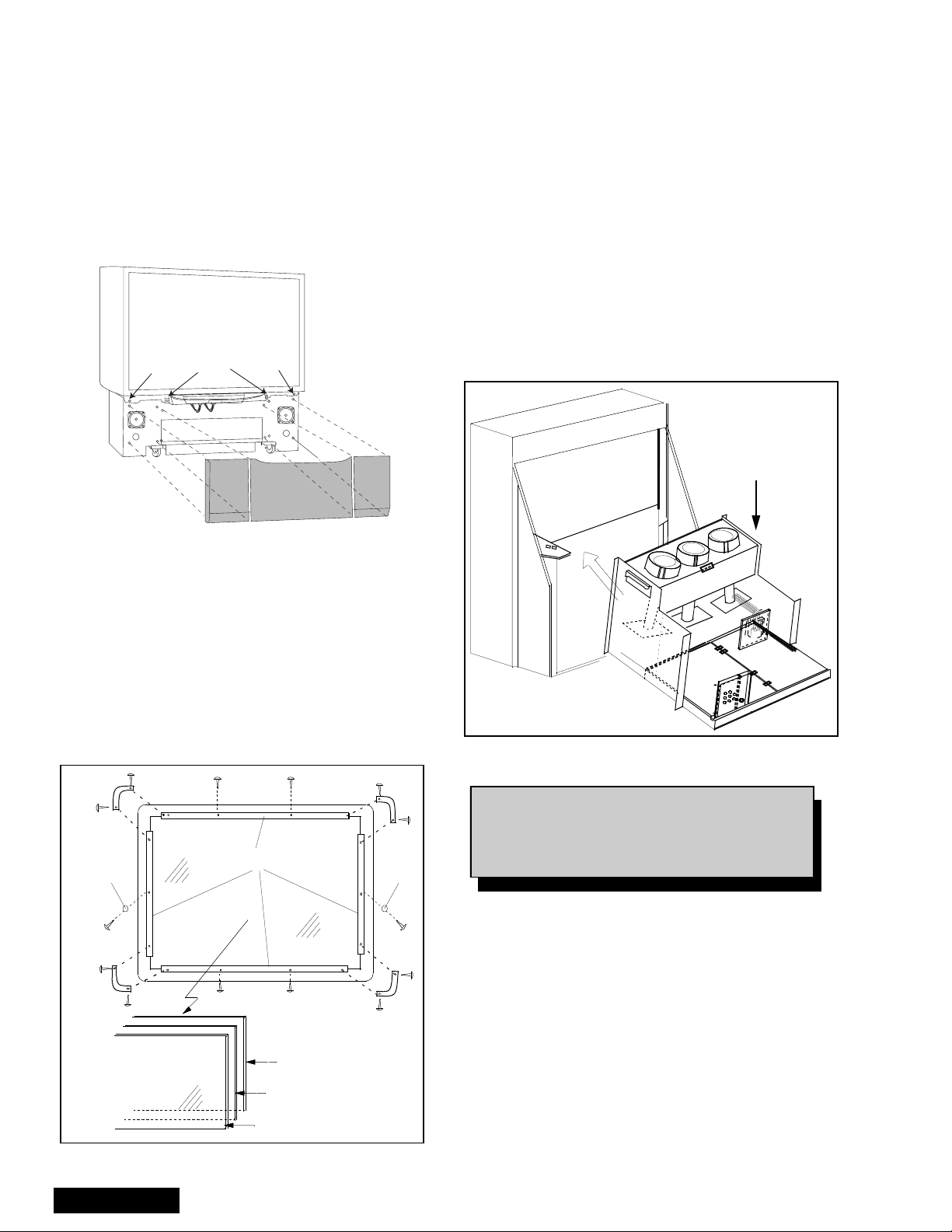
Cabinet Front Removal
(Figure 11)
1. First remove the Speaker Grill and the center
cover, then remove the keyboard, then rem ove th e
bottom back cover and then the top back cover.
2. At this point the front cabinet is only held by two
hex screws shown below, be careful not to push
the cabinet to front.
3. Remove (2) hex cabinet screws (See Figure 11)
the center
Cabinet
Screw
Keyboard
Screws
Cabinet
Screw
CENTER FRONT COVER
cover is held
by four screws
Panasonic
Figure 11. Fr ont Cabinet Removal
Screen Assembly
(Figure 12)
1. First remove the Front Cabinet (See Fro nt Cabinet
Removal procedure)
2. Place Front cabinet face down on a soft surface.
3. Remove screen brac kets from all sides an d corner
brackets
Note: Notice upper, lower, left and right brackets
painted in bla ck (permanent mar ker) on edge,
to avoid reflection on image.
4. Note exact orientation of each screen. The
orientation and order of the screens is critical for
projecting pictures properly. Detailed screen
assembly can be seen in Figur e20.
Main Chassis Block (Light-B ox)
(Figure 13)
1. Remove the Speaker Grill (Figure 8)
2. Remove the cabinet back lower. (Figure 9)
3. The main chassis block is secured to the cabinet
by screws (2 at front, b ehind the dec orative panel ,
4 inside on the bottom of the optical frame).
4. Remove the horizontal barrie r panel at the back of
the cabinet.
5. Unplug connectors (K1, G1 and speaker
connectors) and pull out the main chassis block.
Main Chassis Block
Figure 13. Chassis Removal (Light-Box)
Velcro
Dot
Rear View
Figure 12. Screen Assembly
Service Manual
Screen Brackets
Protective Screen
Lenticular Screen
Fresnel Screen
Velcro
Dot
Note: Main Chassis block can be serviced
either in normal p os iti on or laying on its
back (Protect hookup terminal from
damage).
- 12 -
Disassembly for Service (Continued)
Disassembly for CRT Replacement
To facilitate CRT replacement, the complete CRT
mounting chassis does not need to be removed.
1. Remove the main chassis block from the cabinet
(Figure 13).
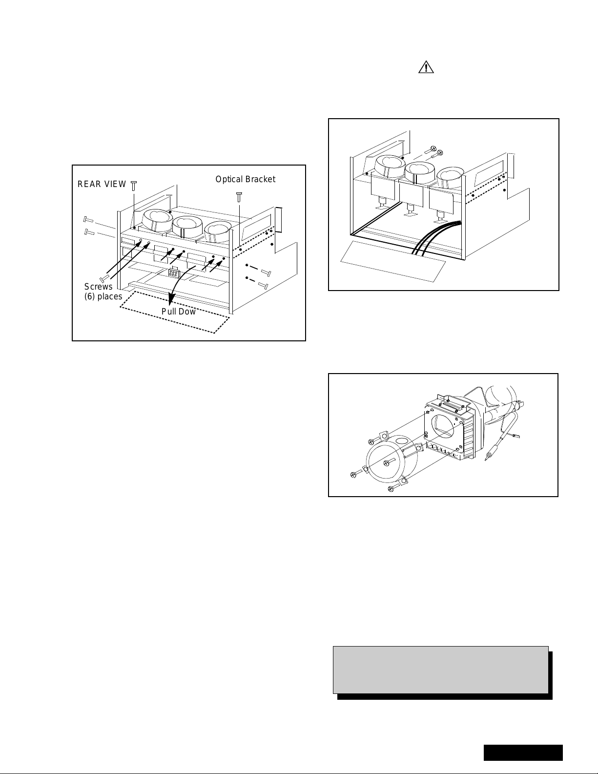
2. Remove the Optical bracket metal cover (rear side)
by removing (6) scr ews from back, (2) screws from
top, and (2) screws fr om each side. (Figure 14)
REAR VIEW
Screws
(6) places
Pull Down
Figure 14. CRT Replacement
3. Remove the defective CRT anode lead from the
high voltage distributor block that is mounted on
the Flyback Transformer. Discharge to CRT
chassis.
4. Unplug connectors from the B-Board. (See board
layout.) B9 for red, B10 for green, or B11 for blue.
5. Unplug the defective CRT black DAG ground
connector from the CRT Board.
6. Remove the CRT Board from the defective CRT
neck.
7. Remove (2) screws from the defective CRT
housing (Figure 15).**
CAUTION: Do not remove the (4) CRT
lens screws.
8. Release CRT anode lead from CRT chassis wire
clamp and all other wires from holders.
9. Loosen a screw that secured the DY and remove i t
from the CRT neck.
Optical Bracket
X-RAYS SHIELD
10. To insure X-Rays radiation protection, the lens
must be mounted in place at all times when power
is applied to the PTV.
Optical Bracket Cover
Figure 15. CRT Replacement.
** CAUTION: Support the CRT Assembly
when loosening screws.
CRT Replacement
1. Remove CRT focus lens assembly (4 screws).
Lens
(4) Screws
Figure 16. CRT Assembly.
2. Lay CRT face down on a soft cloth.
3. Note position of yoke with centering tabs and
remove from defective CRT.
4. Remove CRT DAG ground from defective CRT.
Mount it on the replacement CRT exactly as it was
on the defective CRT.
- 13 -
Note: Replacement CRT is supplied with H.V.
anode lead attached.
When replacing CRTs, please see the part
number on the CRT to be repl aced and order
with same part number on that CRT.
Service Manual
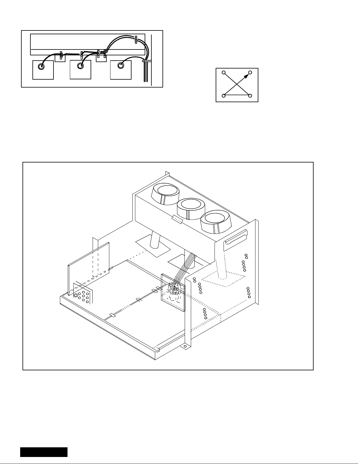
5. Wire the anode lead wire.
Optical Bracket (Front)
7. Press yoke against bell of CRT and tighten the
clamp just snug enough so it will not easily shift.
8. Assemble CRT focus lens asse mbly to new CRT
with (4) screws. Make sure focus lens adjustment
nut is in the same locati on as on other CRT focus
lens.
RED CRT GREEN CRT BLUE CRT
Figure 17. Wire Guide.
6. Install yoke with other CRT neck assemblies on
CRT neck in the same order and position as
removed from the defective CRT.
Optical Block Position Adjustment
1
4
23
Figure 18. CRT Screw Tightening Order.
Note: Please assemble with screws in the order
shown and tighten with the same torque.
Figure 19. Optical Block Position.
The optical block mo unting has holes to allow for the
different size projection screens. These mounts will
adjust to 61 inch & 51 inch projection screens.
51/61
46
51/61
46
51/61
46
51/61
46
51/61
46
51/61
46
If the optical block is removed for service or is
replaced, it is important that the correct mounting holes
are used.
Service Manual
- 14 -

PTV Screen Assemblies
Label on
lower left corner
(front side)
Labels on
opposite sides
Label on
lower left corner
(rear side)
REAR
Protective Screen
FRONT
Front Cabinet
Lenticular Screen
(note vertical ridges)
Fresnel Screen
(note circular ridges)
Figure 20. Screen Assemblies.
B+ Voltages Table
Preparation:
Set the following controls
Picture..........................Normal.
Bright ...........................Normal.
Volume.........................Min. (0).
Procedure:
1. Apply a monoscope pattern.
2. Connect the (-) Lead o f the Digit al Voltmeter to TP
GND1 (Cold Ground).
3. Connect the (+) Lead of the Digital Voltmeter to
each Test Poi nt and confirm th e B+ Voltages (See
Table 3).
No. Test Point (D-Board) Voltage
1 TPD14 138.6±1.0
2 TPD13 19.0
3 TPD12 19.0±1.5
4 TPD11 -19.0
5 TPD10 22.0±1.5
6 C845 (-) -22.5
No. Test Point (A-Board) Voltage
1TPA031 9.0±0.5
2 TPA030 5.0±0.5
Table 3: B+ Voltages Table
±1.5
±1.5
±1.5
- 15 -
Service Manual
CRT Set Up
CAUTION: Insure yoke plugs on the A -Board
are reconnected before turning the PTV
ON to prevent damage to the horizontal
output transistor and/or CRTs.
1. Connect test generator to the antenna terminal an d
set for a monoscope pattern.
2. Loosen yoke clamp , seat yo ke aga inst bell o f CRT
and rotate to correc t yo ke ti lt (co mpare to adjac ent
CRT). Tighten yoke clamp.
3. Remove adhesive from centering tabs and set
centering tabs for zero correction. (Figure 21)
Centering Magnets
Figure 21. Adhesive Removal
4. Cover replacement CRT lens and stati c converge
the tubes not replaced, i f needed. Check size and
linearity of pattern and adjust as required.
5. Uncover replacement CRT lens and cover other
two CRT lenses. Adjust electrical and optical focus
(lens), if required.
6. Uncover all CRT lenses and use yoke centering
magnet to converge replacement CRT (in center
area of screen only) with other two CRTs.
Disregard non-convergence in areas other than
center area.
7. Perform White Balance adjustments.
Dynamic Focus Adjustments
1. Focus adjustments should be performed after 1
hour of aging.
2. Use oscilloscope with 100 : 1 probe.
3. Apply monoscope pattern.
4. Adjust the red, blue and green focus VR on the
focus block for best focus of overall picture of each
CRT. (Figure 24)
D
Adhesive
16.7ms (V Rate)
Procedure:
1. Enter to Service mode and set the following default
DATA:
•H-PAR to +263
•V-SAW to -35
• V-PAR to +117
2. Connect the scope probe to TPD30, GND to
TPD31.
3. Confirm that level of A i s 60 0_V ± 100_V, adjust HPAR DAC to set to specification level.
4. Confirm that level of B is 280_V ± 50_V, adjust VPAR DAC to set to specification level.
5. Confirm that level of C is more tha 20 V, ad just HPAR DAC to set to specification level.
6. Confirm that the waveform shown in D appears
(See Figure 22)
Focus - Electrical & Optical Adjustments
(use for minor adjustment or for final adjustment,
for complete adjustment see following section.)
Electrical Ad just me nt
1. Apply NTSC monoscope pattern.
AB
Adjust electric focus VR
and lens focus on this circle
Figure 23. Lens focus adjustment
Table 4: Focus Points
RED GREEN BLUE
Electric focus B A/B A
Optical Focus B A/B A
280_V ± 100_V
B
> 20_V
C
A
600_V ± 100_V
GND
Figure 22. D. Focus Adjustment Waveform
5. To change DA F DATA, e nter to service mode, then
press POWER on remote to display DACs menu,
then select DAC by pressing CH (RIGHT/LEFT)
and VOL (UP/DOWN), then press ACTION to enter
to DAC, then adjust by pressing VOL (RIGHT/
LEFT); press ACTION, to save press ACTION
again or OTHER to exit without saving.
Service Manual
2. Cover the green and blue CRTs, projecting red
only. The electrical focus controls are located on
the front (Figure 23). Adjust the red focus VR for
best focus as indicated in Table 4).
+
R
+
R
+
+
GB
++
GB
Screen
Focus
Figure 24. Focus Pack
- 16 -
3. Adjust red lens focus (mechanical) until focus is
best.
4. Adjust red focus VR again.
5. Repeat for blue focus VR while projecting blue
only.
6. Repeat for green.
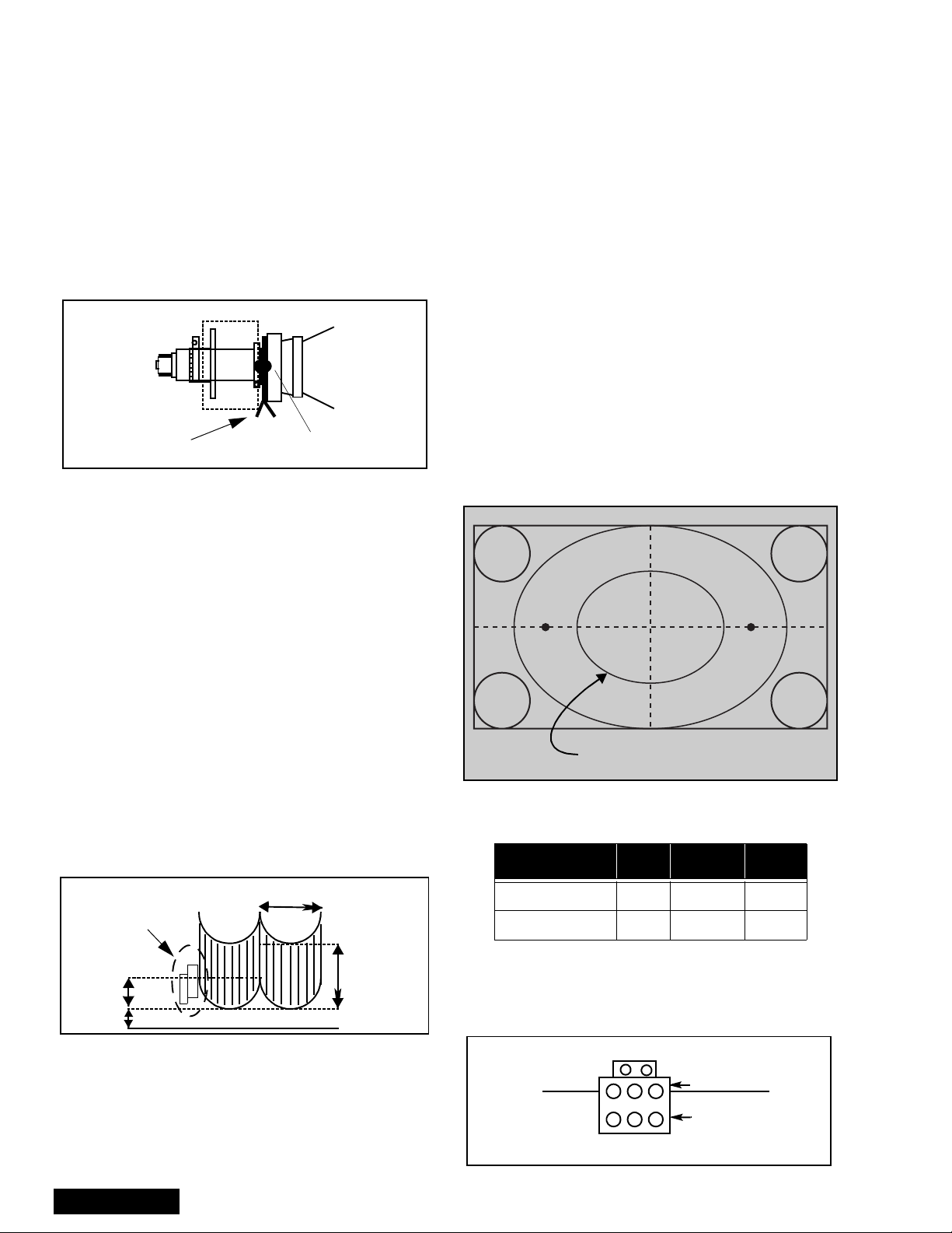
Focus - Optical Lens Adjustment
Optical Adjustments
Note: This adjustment normally should not require
resetting unless th e lens has been rep laced or
adjustment has changed.
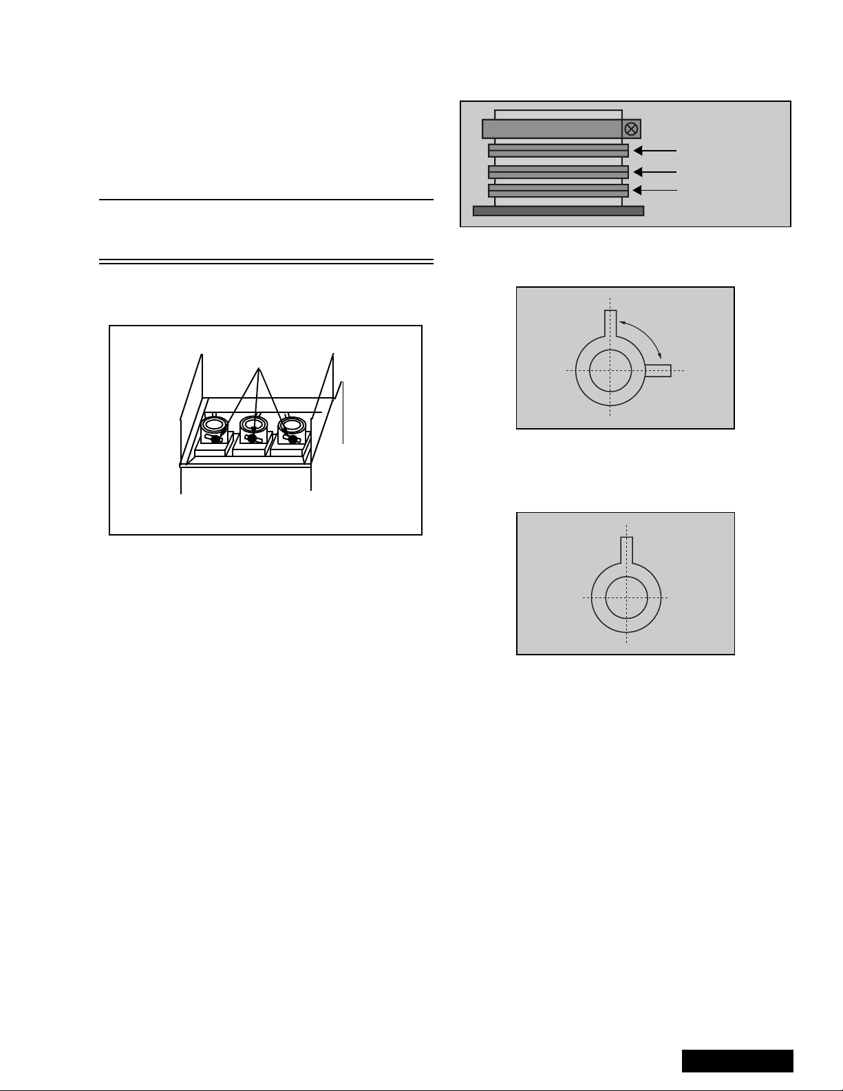
1. Optical focus adjustment is located on the top of
each CRT lens system. Loosen the adjustment
knurled locking knob. (Figure 25)
Adjustment kn ur le d
locking knobs
B G R
4. Position the longer tab of the four-pole magnet to
90 degrees (uncorrected position). (See
Figure 27).
6-pole magnet
(Dummy
4-pole magnet
Alignment magnet
ring)
Figure 26. VM Coil with focus
correction magnet
Set 90 degrees
Figure 27. 4-pole magnet
5. Position the long tab of all alig nment magnets and
of the dummy ring together in an uncorrected
position. (See Figure 28).
REAR VIEW
Figure 25. Optical Lens focus Adjustment
2. Turn the PTV ON. Apply and view a monoscope
pattern.
3. Adjust each lens focus for best focus while viewing
each CRT.
4. Cover the red and blue CRT, projecting green only.
Rotate the green lens for best focus around screen
center area.
5. Do the same for the red focus le ns wh il e pr oj ecting
red only.
6. Repeat for blue.
Electric & VM Focus Adjustment,
Complete adjustment
(Perform this adjustment when a CRT is replaced
or when major adjustment is required)
Preparation:
1. NTSC monoscope pattern.
2. NTSC cross hatch pattern with dots (pincushion).
3. Set DAC MUTE from 0 to 1 (disabling digital
convergence.)
Figure 28. Alignment magnet
(or dummy ring)
Procedure:
1. Apply an NTSC cross hatch pattern with dots.
2. Assure that digital convergence is disabled (Dac
MUTE from 0 to 1).
3. Project red only. (Cover green and blue CRTs.)
4. Turn the red electrical focus adjustment VR (on
focus pack) fully counterclockwise and note the
position of the dots at the center of the picture.
5. Turn the red electrical focus adjustment VR
fully clockwise.
6. If the position of the dots at the center of the screen
moves from the position noted in step 4., adjust the
four pole magnets until the dots are in the same
position as noted in step4.
7. Turn the red electrical focus adjustment VR (on
focus pack) fully counte rclockwise and confirm that
the position of the dots at the c enter of the screen
did not move from their position noted in ste p6.
8. If the position of the dots at the center of screen
moved, repeat from step 4.
- 17 -
Service Manual

9. If the position of the dots moved after repeated
adjustments, adjust unt il the movemen t of the dots
is minimized.
10. Turn the red focus VR fully clockwise.
11. Adjust the 4-pole magnets until the shape of the
dots at the center of the screen is circular.
12. Adjust red focus VR until optimum focus is
achieved.
13. Apply NTSC mo noscope pattern.
14. If the center of the monoscope pattern is not insi de
the 15.0mm circle, shown in Figure 29, adjust the
centering magnets. Repeat the ali gnment magnet
adjustments and four pole magnet adjustments
(step 1. ~ step 12.).
Figure 29. Centering magnet
15. Apply an NTSC cross hatch pattern with dots.
16. Cover red and blue lenses projecting green only.
17. Repeat above procedures for the green.
18. Enable digital convergence by changing DAC
MUTE from 1 to 0.
19. Following adjustments, paint position of DY
centering magnets and fix the centering magnets
of DY, dummy rings of V M coil, four pole magn ets
of VM coil and the alignment magnets of VM coil to
prevent them from movi ng.
Note: Please See “Serviceman Mode (Electronic
Controls)” on page 25 for entering and exit ing
Service Mode.
V ertical Size Adjustme nt (V SIZE)
1. Apply an NTSC monoscope pattern.
2. Cover red and blue lenses.
3. Set DAC MUTE from 0 to 1 (disabling digital
convergence).
4. Adjust centering magnets so that the center of
pattern get aligned with screen frame center.
5. Adjust DAC (VSIZE) until vertical size is 3.5±0.1 on
top and bottom lines. (See Figure 30)
6. Remove lens covers and enable digital
convergence by changing DAC MUTE from 1 to 0.
3.0
1.0
Figure 30. Vertical Size Adjustment
Horizontal Phase Adjustment (H-POS)
1. Apply a crosshatch pattern.
2. Set DAC MUTE from 0 to 1 (disabling digital
convergence).
3. Cover both red and blue lens so that only the green
lens is projecting the monoscope pattern.
4. Turn Green deflection yoke until line is perfectly
horizontal.
5. Adjust H-POS DAC data so that pattern is in the
center of sc reen.
Picture
Area
Screen
Frame
Deflecting
Area
Figure 31. H Phase Adjustment
6. Enable digital convergence by changing DAC
MUTE from 1 to 0.
7. Remove lens covers.
Trapezoid Adjustment (EWTRA)
Procedures:
1. Cover Red and Blue Lenses.
1. Apply a crosshatch pattern.
2. Set DAC MUTE from 0 to 1 (disabling digital
convergence).
3. Adjust DAC EWTRA (trapezoid) by pressing VOL
right-left to co rrect image, less than 30mm on top
and bottom left side(See Figure 32).
Service Manual
Correct Adjustment Incorrect Adjustment
Figure 32. Trapezoid Adjustment
4. Enable digital convergence by changing DAC
MUTE from 1 to 0 and remove caps from lenses.
- 18 -
Pincushion Adjustment (PCC)
Procedure:
1. Cover Red and Blue Lenses.
2. Apply a crosshatc h patt er n.
3. Set DAC MUTE from 0 to 1 (disabling digital
convergence).
4. Adjust DAC PCC (Pincushion) by pressing VOL
right/left and confirm that size is 17±5mm at “A”
(See Figure 33)
“A”
Figure 33. Pincushion Adjustment
5. If Trapezoid adjustment is required after this
adjustment, perform trapezoid adjustment.
6. Enable digital convergence by changing DAC
MUTE from 1 to 0 and remove caps from lenses.
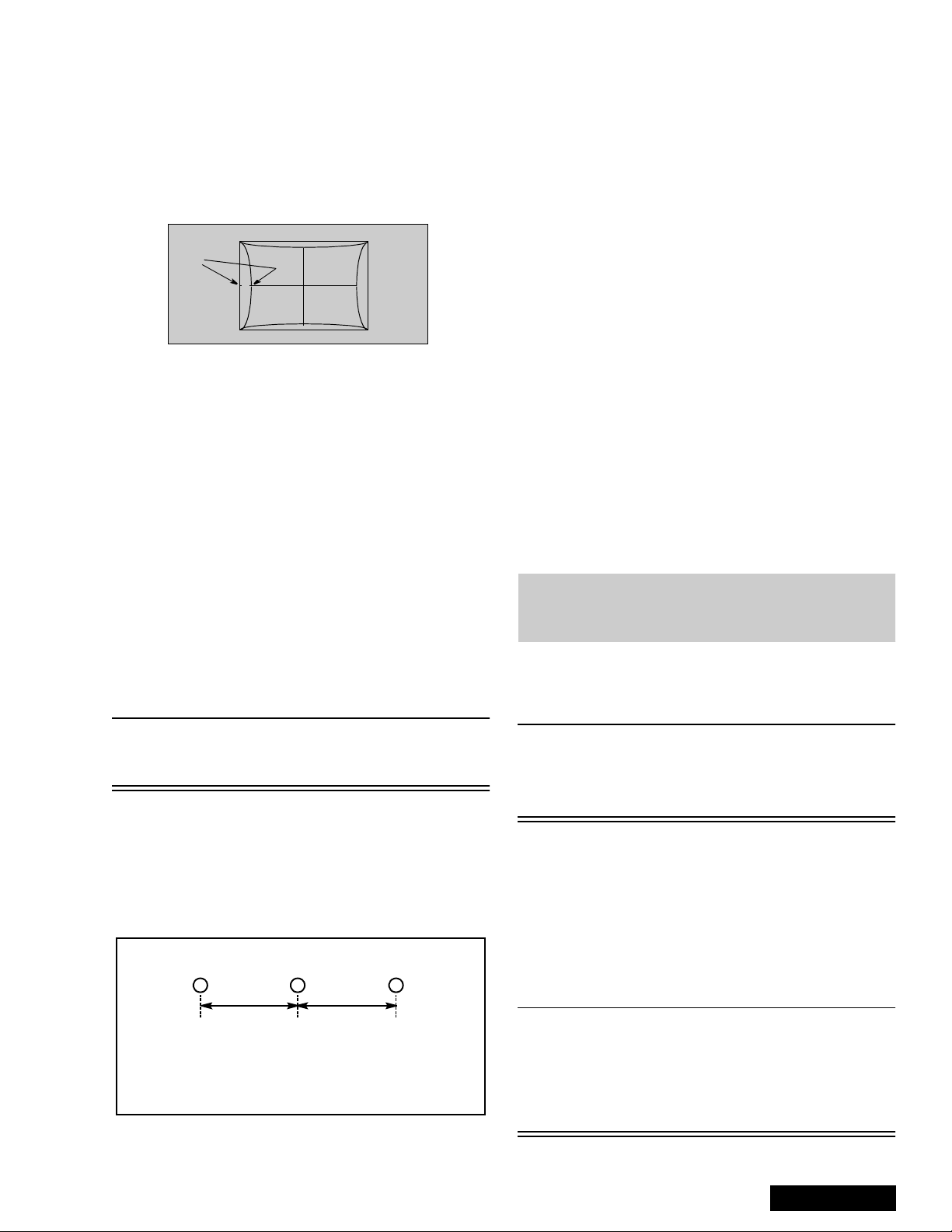
Centering Magnets Adjustment
Procedures:
1. Apply a monoscope pattern.
2. Cover the red and blue lens so only the green lens
is projecting the monoscope pattern.
3. Set DAC MUTE from 0 to 1 (disabling digital
convergence).
4. Loosen the deflection coil screw on the green CRT.
5. Adjust green deflection coil until the horizontal
center li ne is horizontal.
6. Adjust centering magn ets until the gr een pattern is
equal on left and right. Adjust also for horizontal
and vertical tilt.
9. Transfer lens cover from blue to red, so that blue is
projected.
10. Adjust blue deflection coil until the horizontal
center line match es the pattern of the grid and is
leveled.
1 1. Adjust blue centering magnets until the monoscope
pattern center is at the appropriate distance as
indicated on Figure 34.
12. Enable digital convergence by changing DAC
MUTE from 1 to 0.
13. Following the adjustment, make sure that all
deflection coils are pus hed completely toward the
CRT cones and that all screws are tightened.
Horizontal Size Adjustment (H WID)
This is the manual adjust ment of hori zontal siz e that is
included in the automatic convergence adjustment.
1. Apply a monoscope pattern.
2. Set DAC MUTE from 0 to 1 (disabling digital
convergence).
3. Cover both red and blue lens.
4. In service mode, adjust H-WID DAC until the
0.2 lines at left side
picture horizontal s ize is 5.0
of screen.
5. Enable digital convergence by changing DAC
MUTE from 1 to 0.
6. Remove lens covers.
±
Convergence Adjustment
Note: It is strongly rec ommended to first read and
understand the following section prior to
make any adjustment.
T ur n PTV on and allow it to warm up for 30
minutes prior to making adjustments
(WHITE PATTERN).
Note: Push deflection coil to top of CRT neck,
then tighten deflection screw after adjusting
each CRT centering and Tilt.
7. Transfer lens cover from r ed to green and proj ect
red only. Adjust deflection coil un til the horizontal
center line matches the pattern of the grid and is
leveled.
8. Adjust red centeri ng magnets unt il the mono scope
pattern center is at the appropriate distance as
indicated on Figure 34.
RG
dd
d measured in mm
28 mm
Figure 34. Centering Magnets Adjustment.
B
Note: This PTV uses the scheme described
below to correct for misconvergence of the
three CRT projection tubes. There are
various modes to this operation.
Preparation:
Place the Convergence Alignment Template (see
“Convergence Alignment Template” on page 24) over
the PTV screen. Align the ce nter lines of the template
with the mechanical center markers on the PTV screen
frame. If the template is not available, create one using
the dimensions provided in “Convergence Alignment
Template” on page 24.
Remote control must be used during the procedure.
Note: Apply the Conv ergenc e Alignm ent Template to
the PTV screen frame to co nverge the Green
Raster only. Remove the Convergence
Alignment Template following this alignment.
The red and blue r asters can then be a ligned
to the green raster.
- 19 -
Service Manual
 Loading...