

Panasonic PT-51G44A, PT-51G54A, PT-51G44CA, PT-61G54CA, PT-51G54CA Service Manual
...
ORDER NO. MTC9903012Cl
82
Service
Manual
7
Color Video Projection System
Main Manual
(P3)
Models
Chassis
PT-51 G44A AP815
PT-51 G44CA AP815
PT-51 G54A AP815
PT-51 G54CA AP815
PT-61 G54A BP815
PT-61 G54CA BP815
Note:
Refer to Technical Guide
(P3)
for
functional descriptions and Block
Diagrams.
(MTC9703689G1).
This Service manual is issued as a service guide for the models of the P3 family listed above. Included in this manual
are a set of schematic, block diagrams, functional descriptions, alignment procedures, disassembly procedures, and a
complete parts list.
"WARNING!
This Service Manual is designed for experienced repair technicians only and is not designed for use by the general public.
It does not contain warnings or cautions to advise non-technical individuals of potential dangers in attempting to service a product.
Products powered by electricity should be serviced or repaired only by experienced professional technicians.
Any attempt to
service or repair the product or products dealt with in this Service Manual by anyone else could result in serious injury or death."
Panasonic,
Copyright
1999
by Matsushita Electric Corporation of
America. All rights reserved. Unauthorized copying
and distribution is a violation of law.
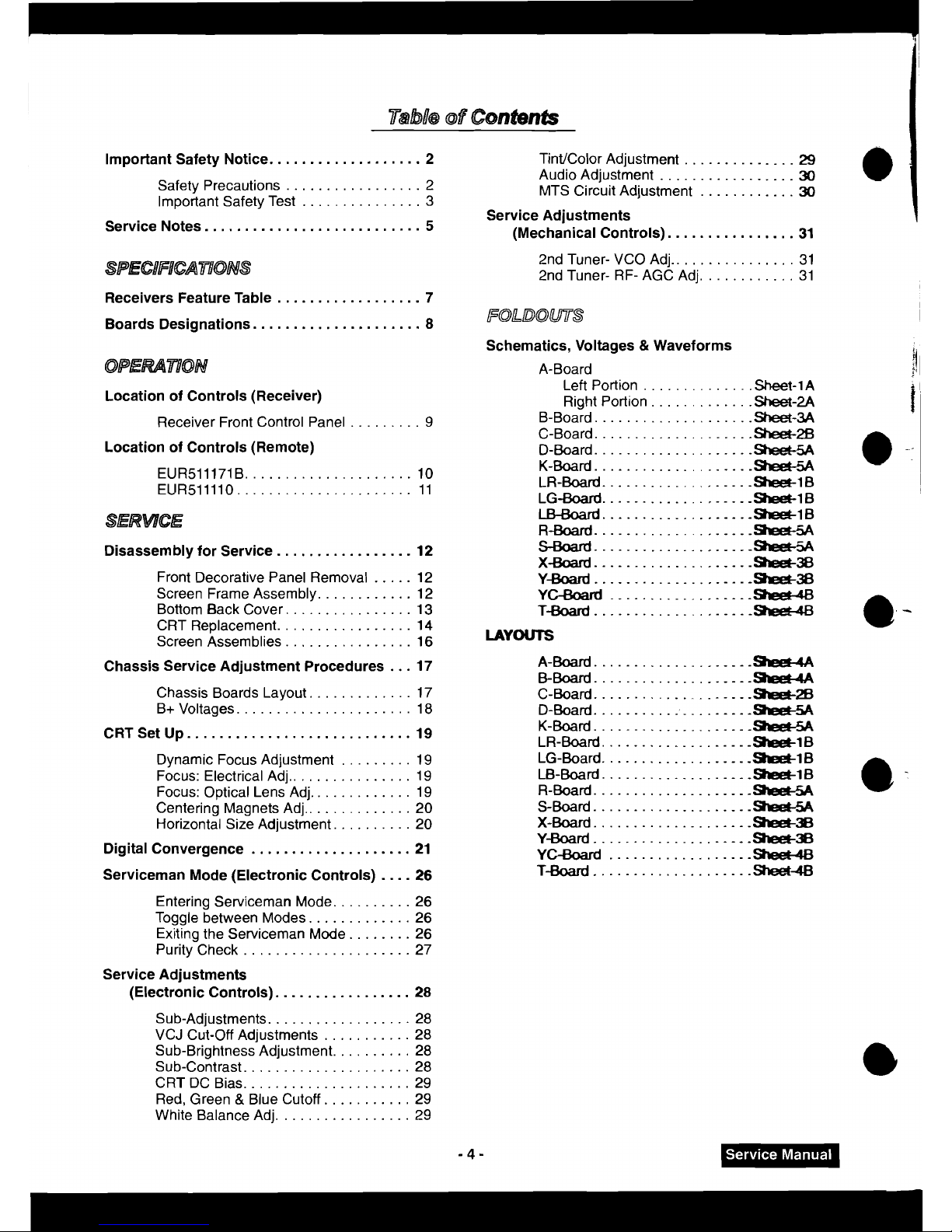
Important Safety Notice
...................
2
TintJColor Adjustment
..............
29
Audio Adjustment
.................
30
Safety Precautions
.................
2
MTS Circuit Adjustment
............
30
...............
Important Safety Test
3
Service Adjustments
Service Notes
...........................
5
(Mechanical Controls)
................
31
2nd Tuner- VCO Adj
.............
2nd Tuner- RF- AGC Adj
.........
Receivers Feature Table
..................
7
Boards Designations 8
FOLDOUTS
i
.....................
Location of Controls (Receiver)
.........
Receiver Front Control Panel 9
Location of Controls (Remote)
Disassembly for Service
.................
12
Front Decorative Panel Removal
.....
12
Screen Frame Assembly
............
12
Bottom Back Cover
................
13
CRT Replacement
.................
14
Screen Assemblies
................
16
Chassis Service Adjustment Procedures
...
17
Chassis Boards Layout
.............
17
B+ Voltages ...................... 18
CRT Set Up
............................
19
Dynamic Focus Adjustment
.........
19
Focus: Electrical Adj
................
19
Focus: Optical Lens Adj
.............
19
Centering Magnets Adj
..............
20
Horizontal Size Adjustment
..........
20
Digital Convergence
....................
21
....
Serviceman Mode (Electronic Controls) 26
Entering Serviceman Mode
..........
26
Toggle between Modes
.............
26
Exiting the Serviceman Mode
........
26
Purity Check
.....................
27
Service Adjustments
(Electronic Controls)
.................
28
Schematics. Voltages
&
Waveforms
a,
A-Board
j!
1
Left Portion
..............
Sheet-1
A
Right Portion
............
.Sheet
.2A
B-Board
....................
Sheet-3A
C-Board
Sheet-26
I!
....................
....................
D-Board
K-Board
ske+A
-:
....................
LR.Board
..................
B
LG-Board
..................
B
LBBoard
..................
.-
16
R-Board
....................
Se&+5A
SBoard
....................-
XBoard
....................
-38
Y-Board
....................
-38
YC-Board
.................
-9reelldS
TBoard
....................
LAYOUTS
e
-
A-Board
...................
.-
&Board
...................
--
C- Board
....................
Swa-28
D-Board
..........
:
........
-9PeC5A
K-Board
...................
zwx+5A
LR-Board
..................
-SreeclB
LG.Board
...................
SleeC1
B
LB-Board
...................
-16
R-Board
....................
SreetSA
S-Board
SreeCSA
e-
....................
X-
Board
....................
-38
yard
....................
-3B
YC-Board
..................
sheet46
T-Board
....................
Sheei4
Sub.Adjustments
..................
28
VCJ Cut-Off Adjustments
...........
28
Sub-Brightness Adjustment
..........
28
Sub.Contrast
.....................
28
CRT DC Bias
.....................
29
Red, Green
&
Blue Cutoff
...........
29
White Balance Adj
.................
29
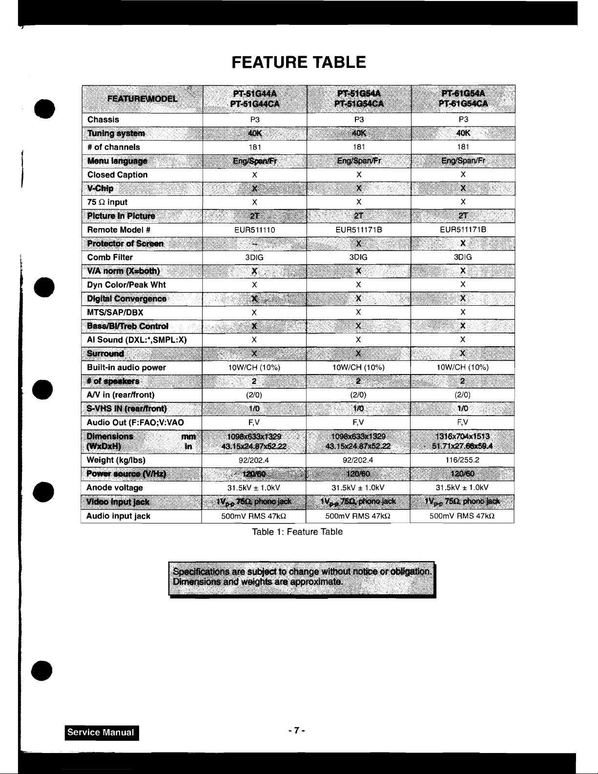
FEATURE
TABLE
Table 1 :
Feature Table
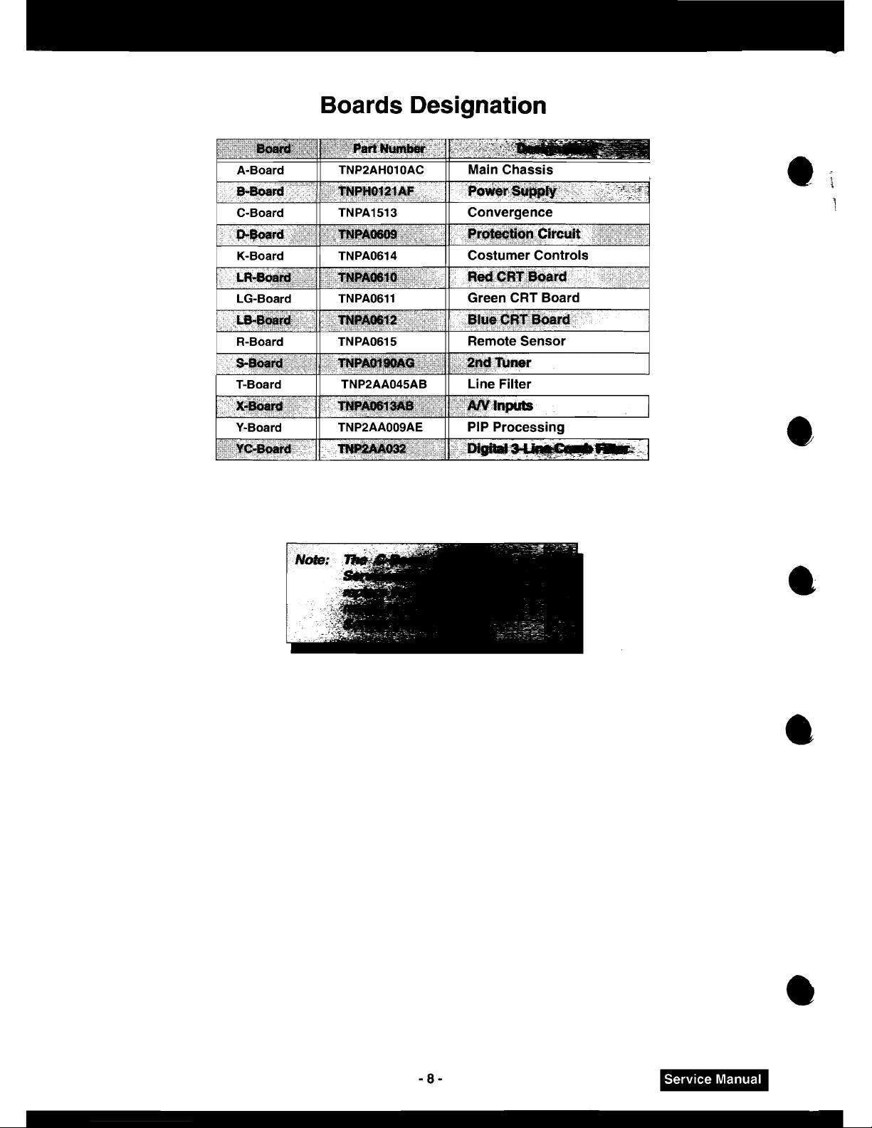
Boards Designation
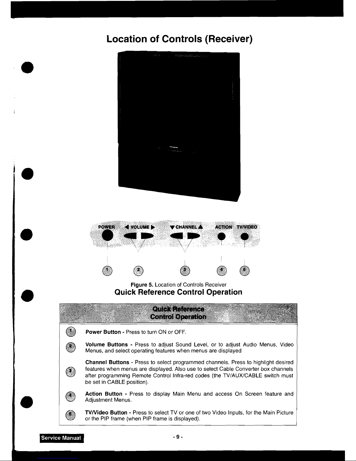
Location of Controls (Receiver)
POWER
(
VOLUME,
'l
CHANNEL
A
ACTtON
TVNlDEO
e
I
FC
.
I
I.
.
I
9-
.
..
.
,
,,
.
+
+
. .
I
Figure
5.
Location of Controls Receiver
Quick Reference Control Operation
Power Button - Press to turn OIV or OFF.
Volume Buttons - Press to adjust Sound Level, or to adjust Aud~o Menus, Video
Menus, and select operating features when menus are displayed
Channel Buttons - Press to select programmed channels. Press to highlight desired
features when menus are displayed. Also use to select Cable Converter box channels
@
after programming Remote Control infra-red codes (the TV/AUX/CABLE switch must
be set in CABLE position).
Action Button - Press to display Main Menu and access On Screen feature and
Adjustment Menus.
TVNideo Button - Press to select TV or one of two Video Inputs, for the Main Picture
or the PIP frame (when PIP frame is displayed).
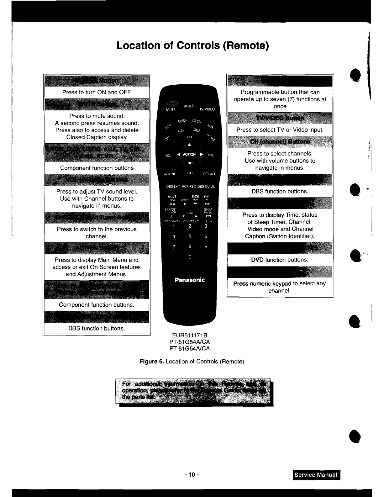
Location of Controls (Remote)
11
Press to turn ON and OFF.
11
A
second press resumes sound.
Press also to access and delete
Closed Caption display.
1)
Component function buttons
(1
Press to adjust TV sound level.
Use with Channel buttons to
navigate in menus.
Press to switch to the previous
1
I
Component function buttons.
/
1
DBS function buttons.
Programmable button that can
operate up to seven (7) functions at
once
11
Press to select TV or Video input.
I
Press to select channels.
Use with volume buttons to
navigate in menus.
I I
DBS function buttons.
I
I
11
Press to display Time, status
of Sleep Timer. Channel,
Mdeo
mode and Channel
Caption
(Stabn Identifier).
!I
DVD
function buttons.
1-
i
1
Press
numeric
keypad to select any
channel.
I
Figure
6.
Location of Controls (Remote)
I
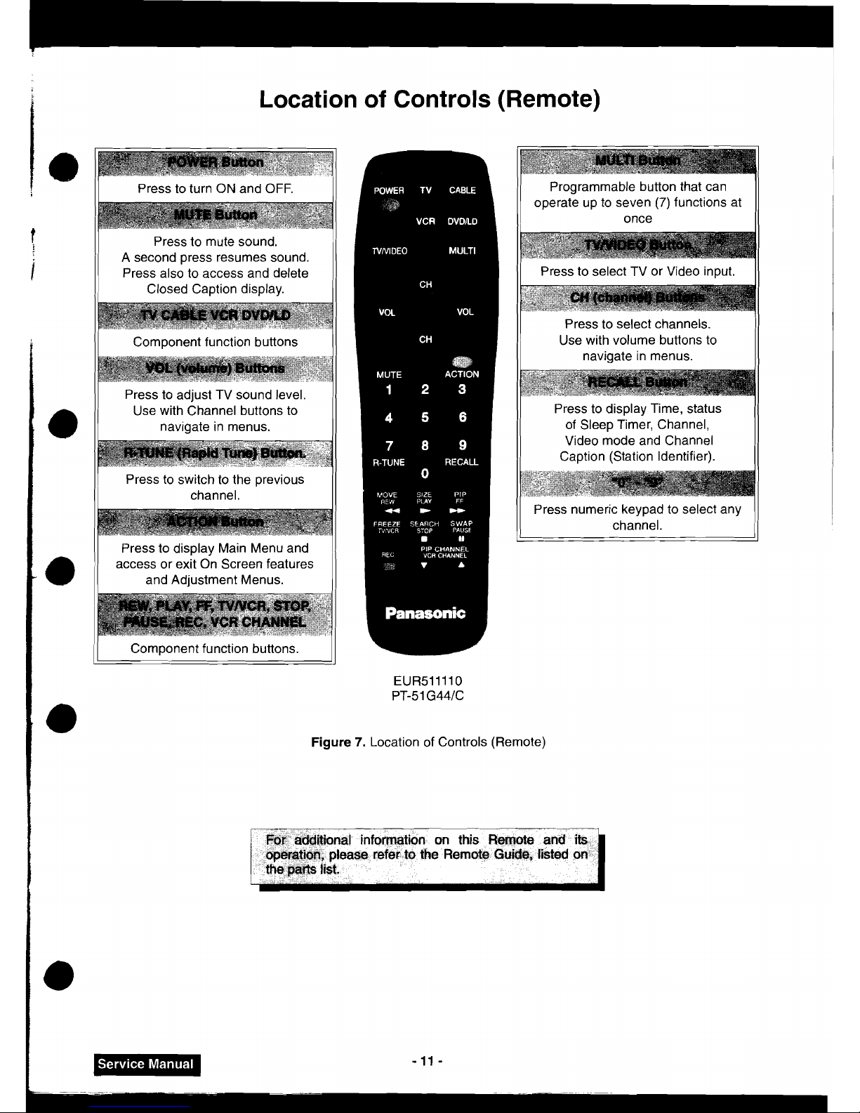
Location of Controls (Remote)
I
I
Press to turn ON and OFF.
I I
Press to mute sound.
A second press resumes sound.
Press also to access and delete
I
Closed Caption display.
11
Component function buttons
)I
Press to adjust TV sound level.
Use with Channel buttons to
navigate in menus.
II
ress to switch to the previous
channel.
11
Programmable button that can
operate up to seven
(7)
functions at
once
I(
Press to select TV or Video input.
11
Press to select channels.
I
Use with volume buttons to
navigate in menus.
Press to display Main Menu and
1
access or exit On Screen features
and Adjustment Menus.
I
Component function buttons.
U
Figu
Ire
!
7.
Location of Controls
(Re
--
Press to display Time, status
of Sleep Timer, Channel,
Video mode and Channel
Caption (Station Identifier).
--
-
-1
Press numeric keypad to select any
channel.
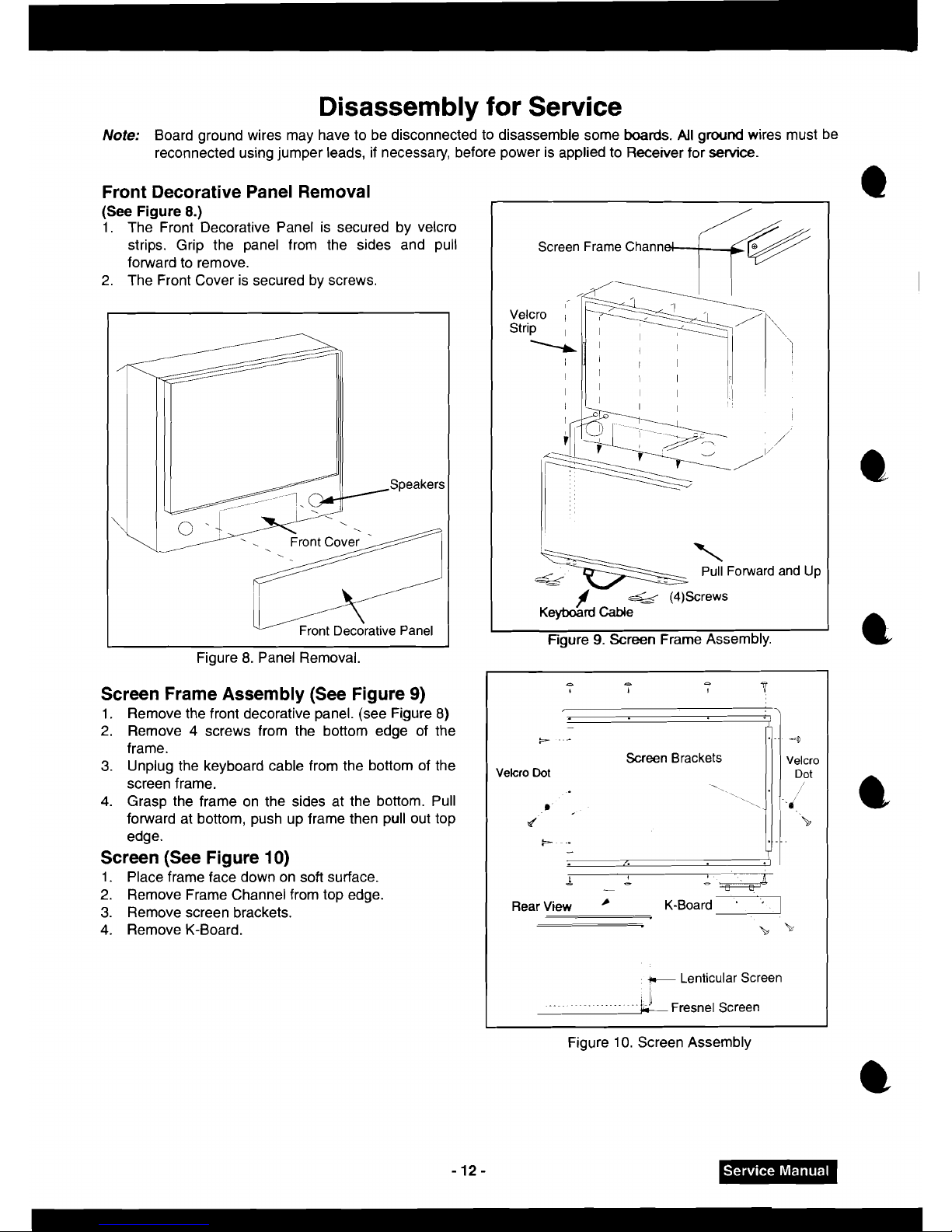
Disassembly
for
Service
Note:
Board ground wires may have to be disconnected to disassemble some
boards.
All
ground wires must be
reconnected using jumper leads, if necessary, before power is applied to Receiver for
service.
Front Decorative Panel Removal
(See
Figure
8.)
1.
The Front Decorative Panel is secured by velcro
strips. Grip the panel from the sides and pull
forward to remove.
2.
The Front Cover is secured by screws.
VJ
lecorative Panel
Figure 8. Panel Removal.
Screen Frame Assembly (See Figure
9)
1.
Remove the front decorative panel. (see Figure 8)
2.
Remove 4 screws from the bottom edge of the
frame.
3.
Unplug the keyboard cable from the bottom of the
screen frame.
4.
Grasp the frame on the sides at the bottom. Pull
forward at bottom, push up frame then pull out top
edge.
Screen (See Figure
10)
1.
Place frame face down on soft surface.
2.
Remove Frame Channel from top edge.
3.
Remove screen brackets.
4.
Remove K-Board.
Screen Frame Chann
#@
I
\
Pull Forward and
Up
4
f
e&
(4)Screws
Keyboard Cable
I
I
Figure
9.
Screen Frame Assembly.
a a
4
6
1
1
fS
-
k-
-.-
4
Screen Brackets
Velcro
Velcro
Dot
Dot
',
."
r
B
b
-
..
.
--.
-
L
I
I
!
-
-
-
I
,-
-
Rear
View
'
K-Board
'1
b
\<
-
Lenticular Screen
..-~
~~~-.~.......~-.
Fresnel Screen
Figure
10.
Screen Assembly
Disassembly for Service (Cont.)
Disassembly
of
Speaker Units Replacement
1. Remove the front decorative panel located under
control panel. (see Figure 8)
2. Each Left and Right speaker is secured to the
cabinet with (4) screws for each bracket.
3. Disconnect the
R & L speaker lead connectors
from the speaker units.
6
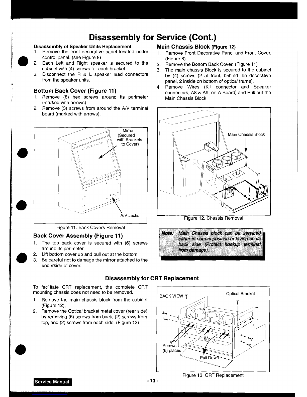
Bottom Back Cover (Figure
11)
\
1. Remove (8) hex screws around its perimeter
(marked with arrows).
2.
Remove (3) screws from around the
AN
terminal
board (marked with arrows).
AN
Jacks
Main Chassis Block
(Figure
12)
1. Remove Front Decorative Panel and Front Cover.
(Figure 8)
2. Remove the Bottom Back Cover. (Figure 11
)
3. The main chassis Block is secured to the cabinet
by (4) screws (2 at front, behind the decorative
panel, 2 inside on bottom of optical frame).
4. Remove Wires (K1 connector and Speaker
connectors, A8
&
A9, on A-Board) and Pull out the
Main Chassis Block.
I
Figure 12. Chassis Removal
Figure 11. Back Covers Removal
Back Cover Asserrrbly (Figure
11)
1. The top back cover is secured with (6) screws
around its perimeter.
2. Lift bottom cover up and pull out at the bottom.
/
3.
Be careful not to damage the mirror attached to the
I
underside of cover.
I
Disassembly for CRT Replacement
To facilitate CRT replacement, the complete CRT
mounting chassis does not need to be removed.
1. Remove the main chassis block from the cabinet
(Figure
12),
2. Remove the Optical bracket metal cover (rear side)
by removing (6) screws from back, (2) screws from
top, and (2) screws from each side. (Figure 13)
BACK VIEW
Optical Bracket
/I
Figure 13. CRT Replacement
-13-
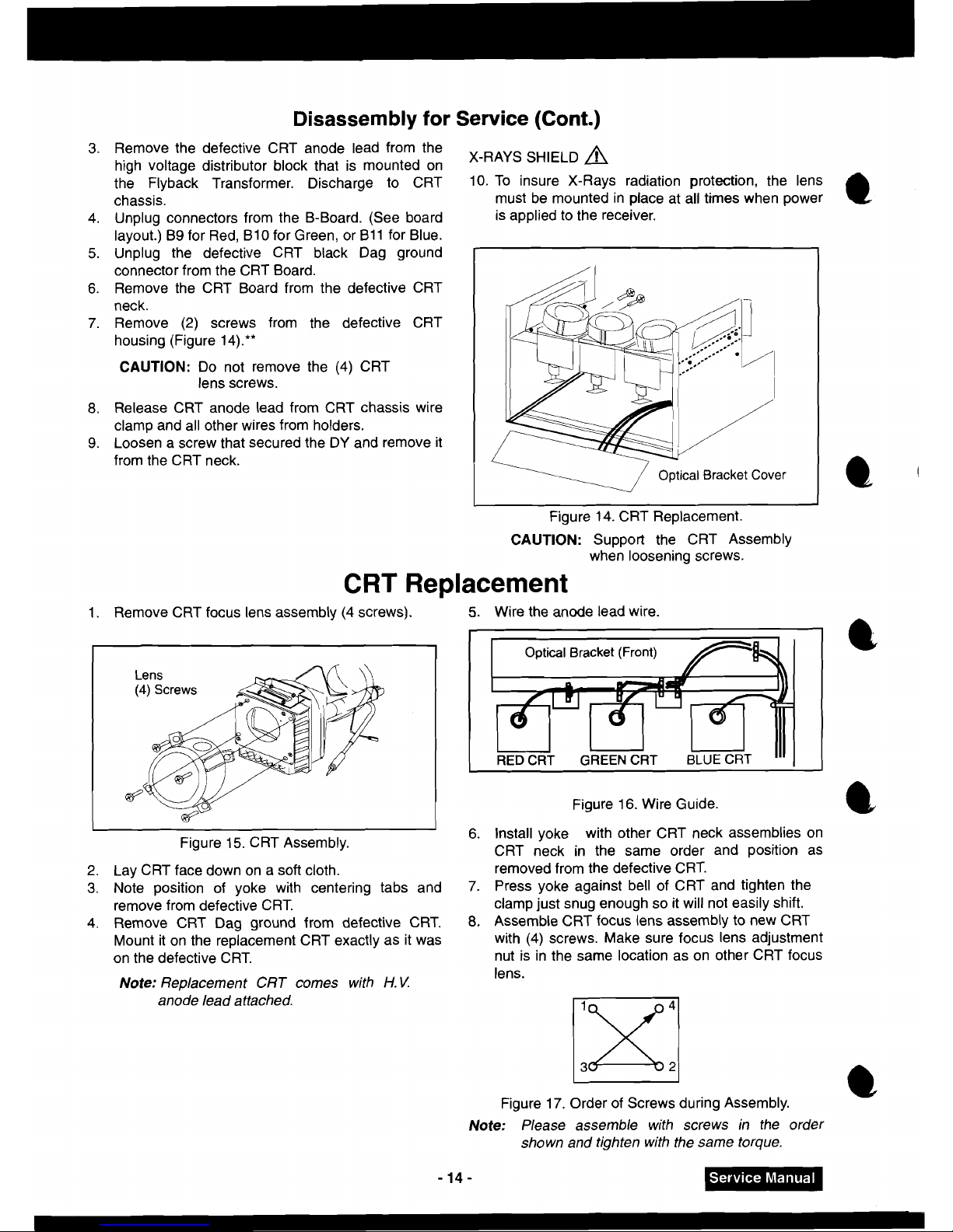
Disassembly
for
Service
(Cont.)
3.
Remove the defective CRT anode lead from the
high voltage distributor block that is mounted on
X-RAYS SHIELD
A
the Flyback Transformer. Discharge to CRT 10. TO insure X-Rays radiation protection, the lens
chassis.
must be mounted in place at all times when power
4. Unplug connectors from the B-Board. (See board
is applied to the receiver.
layout.)
B9 for Red, 810 for Green, or I311 for Blue.
5. Unplug the defective CRT black Dag ground
connector from the CRT Board.
6. Remove the CRT Board from the defective CRT
neck.
7. Remove (2) screws from the defective CRT
housing (Figure
14).**
CAUTION:
Do not remove the (4) CRT
lens screws.
8.
Release CRT anode lead from CRT chassis wire
clamp and all other wires from holders.
9. Loosen a screw that secured the DY and remove it
from the CRT neck.
Optical Bracket Cover
-
~i~ure 14. CRT Replacement.
CAUTION:
Support the CRT Assembly
when loosening screws.
CRT Replacement
1.
Remove CRT focus lens assembly (4 screws).
5.
Wire the anode lead wire.
Figure 16. Wire Guide.
6.
Install yoke with other CRT neck assemblies on
CRT neck in the same order and position as
removed from the defective CRT.
7.
Press yoke against bell of CRT and tighten the
clamp just snug enough so it will not easily shift.
8.
Assemble CRT focus lens assembly to new CRT
with (4) screws. Make sure focus lens adjustment
nut is in the same location as on other CRT focus
lens.
Figure 15. CRT Assembly.
2. Lay CRT face down on a soft cloth.
3.
Note position of yoke with centering tabs and
remove from defective CRT.
4. Remove CRT Dag ground from defective CRT.
Mount it on the replacement CRT exactly as it was
on the defective CRT.
Note:
Replacement CRT comes with
H.
V.
anode lead attached.
Figure 17. Order of Screws during Assembly.
C
Note:
Please assemble with screws in the order
shown and tighten with the same torque.
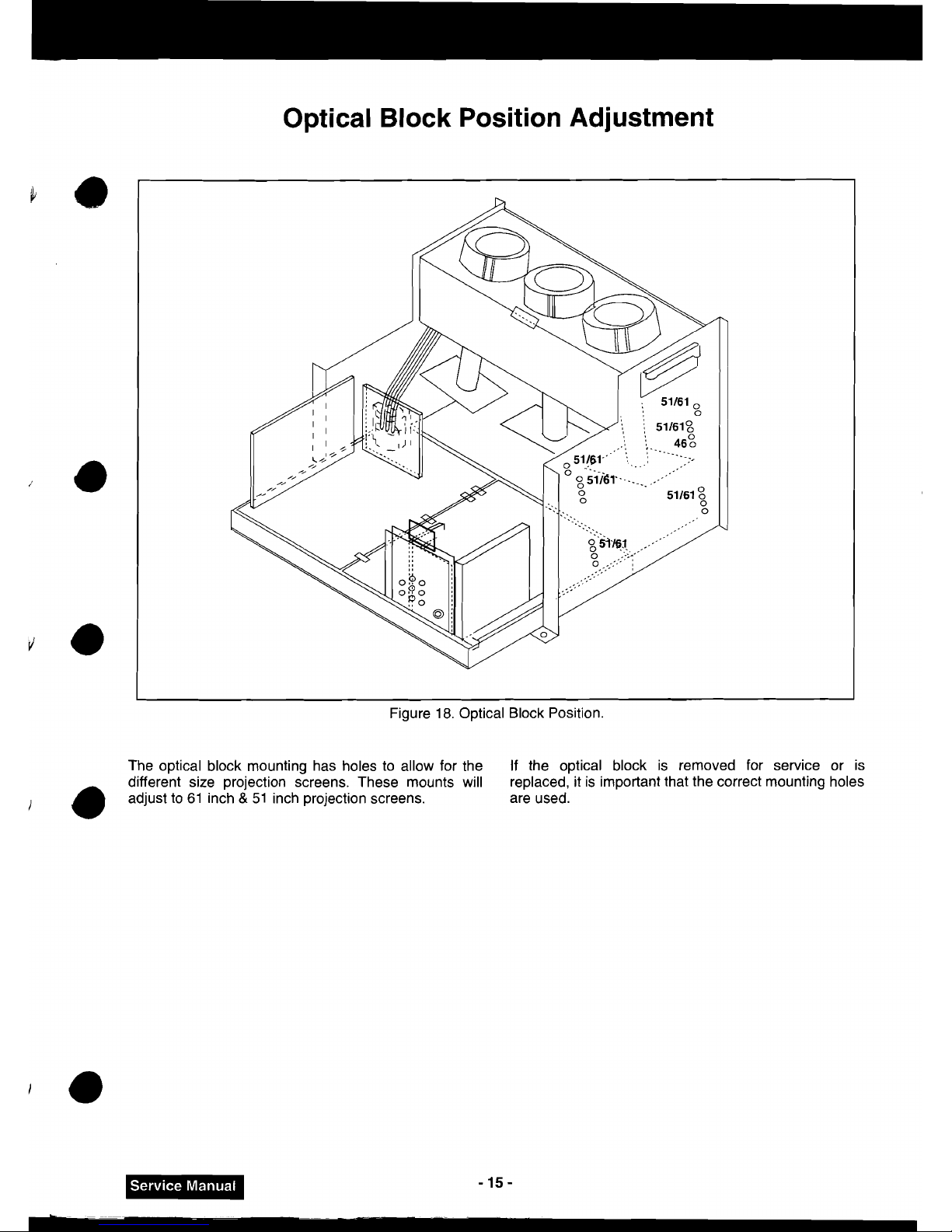
Optical Block Position Adjustment
Figure
18.
Optical Block Position.
The optical block mounting has holes to allow for the
If
the optical block is removed for service or is
different size projection screens. These mounts will replaced, it is important that the correct mounting holes
adjust to
61
inch
&
51
inch projection screens. are used.
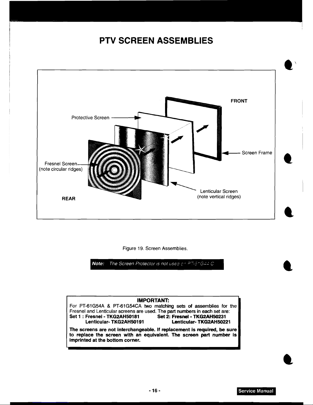
PTV
SCREEN ASSEMBLIES
Protective Screen
Screen Frame
Fresnel Screen
(note circular
r~dges)
Lentrcular Screen
REAR
(note vertical rldges)
Figure
19.
Screen Assemblies.
IMPORTANT:
For PT-61G54A & PT-61G54CA two matching
sets
of
assemblies for the
Fresnel and Lenticular screens are used. The
part
numbers
in each set are:
Set 1 : Fresnel - TKG2AH50181
Set
2: Fresnel - TKG2AH50231
Lenticular- TKG2AH50191 Lenticular- TKG2AH50221
The screens are not interchangeable. If replacement is required, be sure
to replace the screen with an equivalent. The screen
part
number is
imprinted at the bottom corner.
I
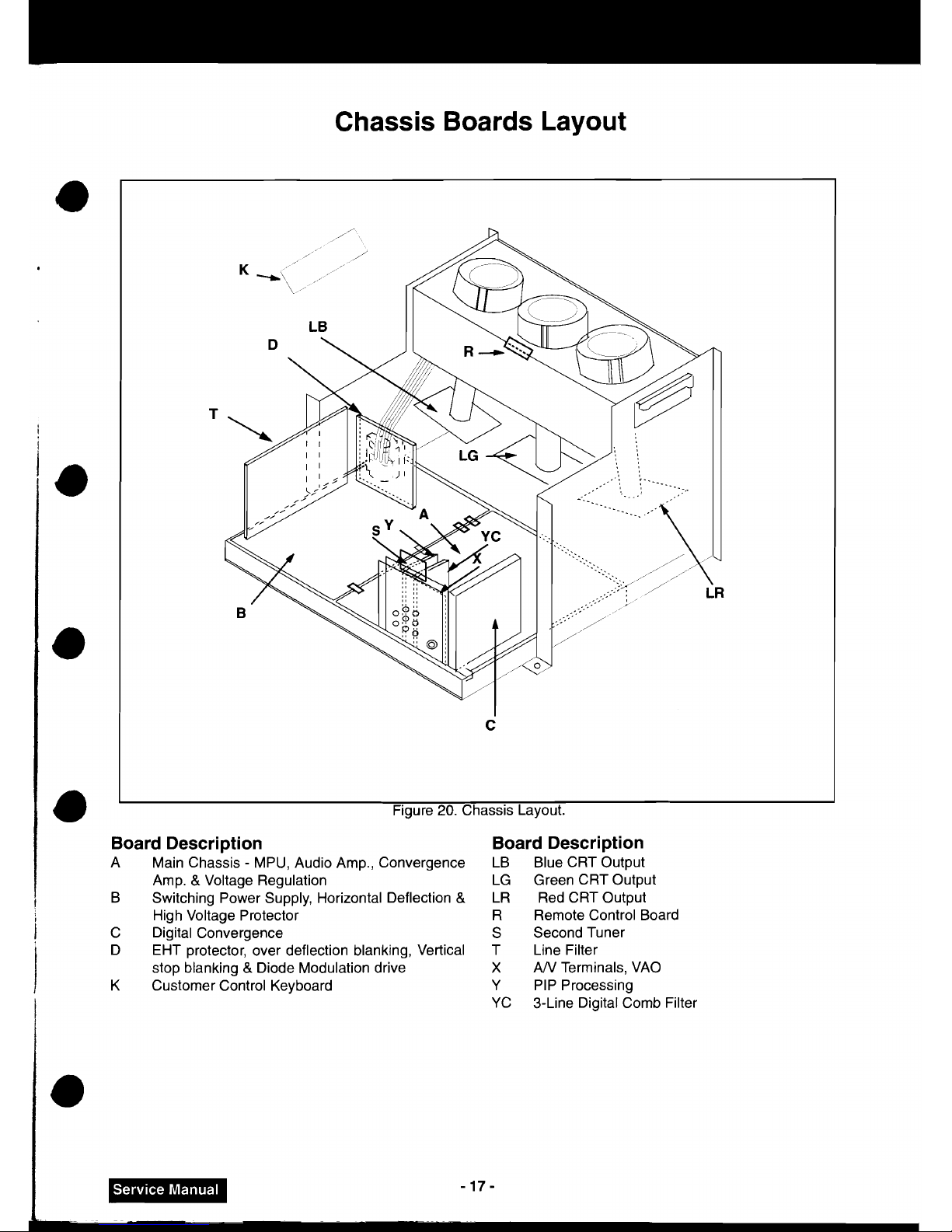
Chassis Boards Layout
i
1
..
T
I
C
Figure
20.
Chassis Layout.
!
Board Description Board Description
A Main Chassis - MPU, Audio Amp., Convergence LB Blue CRT Output
Amp.
&
Voltage Regulation LG Green CRT Output
B Switching Power Supply, Horizontal Deflection
&
LR Red CRT Output
High Voltage Protector
R Remote Control Board
I
C Digital Convergence
S Second Tuner
D EHT protector, over deflection blanking, Vertical T Line Filter
stop blanking
&
Diode Modulation drive
X
AN
Terminals, VAO
K Customer Control Keyboard Y PIP Processing
i
YC 3-Line Digital Comb Filter
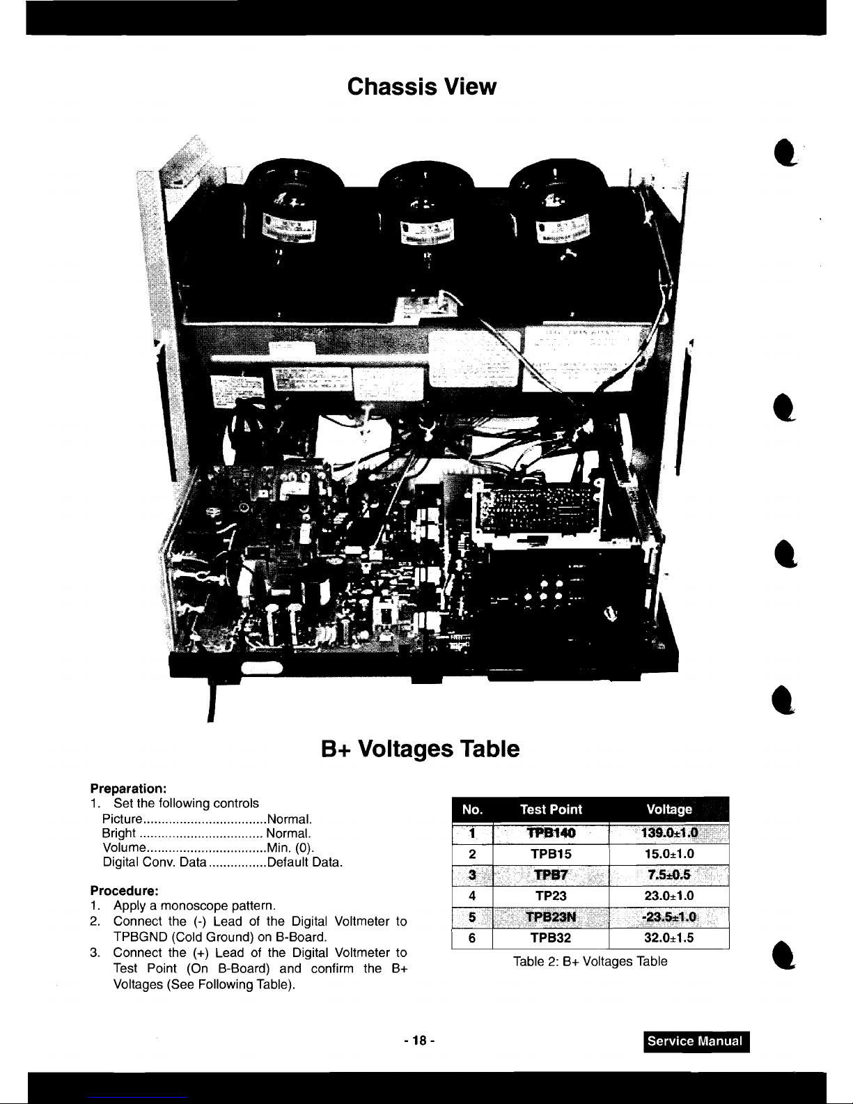
Chassis View
B+
Voltages Table
Preparation:
1.
Set the following controls
Picture
..................................
IYormaI.
Bright
..................................
Normal.
Volume
.................................
Mi.
(0).
Digital Conv. Data
................
Default Data.
Procedure:
1.
Apply a monoscope pattern.
2.
Connect the
(-)
Lead of the Digital Voltmeter to
TPBGND (Cold Ground) on
6-Board.
3.
Connect the
(+)
Lead of the Digital Voltmeter to
Test Point (On
6-Board) and confirm the B+
Voltages (See Following Table).
Table
2:
B+ Voltages Table
CRT
Set
Up
.-----------,
Adhesive
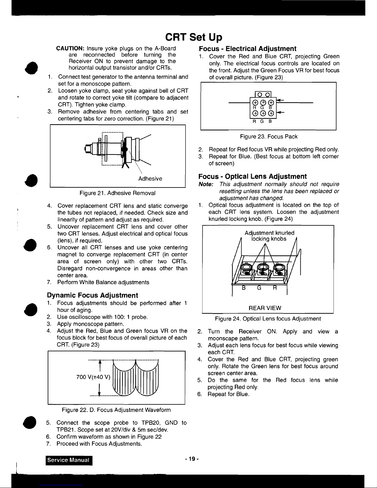
CAUTION:
Insure yoke plugs on the A-Board
Focus - Electrical Adjustment
are reconnected before turning the
1.
Cover the Red and Blue CRT, projecting Green
Receiver ON to prevent damage to the only. The electrical focus controls are located on
horizontal output transistor
and/or CRTs.
the front. Adjust the Green Focus VR for best focus
1.
Connect test generator to the antenna terminal and
of overall picture. (Figure 23)
Figure 21. Adhesive Removal
set for a monoscope pattern.
2. Loosen yoke clamp, seat yoke against bell of CRT
.
and rotate to correct yoke tilt (compare to adjacent
CRT). Tighten yoke clamp.
3. Remove adhesive from centering tabs and set
centering tabs for zero correction. (Figure 21)
4. Cover replacement CRT lens and static converge
L
the tubes not replaced, if needed. Check size and
linearity of pattern and adjust as required.
5.
Uncover replacement CRT lens and cover other
two CRT lenses. Adjust electrical and optical focus
(lens), if required.
6.
Uncover all CRT lenses and use yoke centering
magnet to converge replacement CRT (in center
area of screen only) with other two
CRTs.
Disregard non-convergence in areas other than
center area.
7.
Perform White Balance adjustments
-%-r
000
RGB
Dynamic Focus Adjustment
1.
Focus adjustments should be performed after 1
hour of aging.
2. Use oscilloscope with 100: 1 probe.
3. Apply monoscope pattern.
4. Adjust the Red, Blue and Green focus VR on the
focus block for best focus of overall picture of each
CRT. (Figure 23)
Figure 22. D. Focus Adjustment Waveform
Figure 23. Focus Pack
2. Repeat for Red focus VR while projecting Red only.
3. Repeat for Blue. (Best focus at bottom left corner
of screen)
Focus - Optical Lens Adjustment
Note:
This adjustment normally should not require
resetting unless the lens has been replaced or
adjustment has changed.
1.
Optical focus adjustment is located on the top of
each CRT lens system. Loosen the adjustment
knurled locking knob. (Figure 24)
Adjustment knurled
REAR
VIEW
Figure 24. Optical Lens focus Adjustment
2. Turn the Receiver ON. Apply and view a
moonscape pattern.
3. Adjust each lens focus for best focus while viewing
each CRT.
4. Cover the Red and Blue CRT, projecting green
only. Rotate the Green lens for best focus around
screen center area.
5.
Do the same for the Red focus lens while
projectiug Red only.
6.
Repeat for Blue.
5. Connect the scope probe to TPB20, GND to
TPB21. Scope set at 20VIdiv & 5m secldev.
6.
Confirm waveform as shown in Figure 22
7.
Proceed with Focus Adjustments.
 Loading...